WO2019230897A1 - 矯正装置及びそれを備えるロボット - Google Patents
矯正装置及びそれを備えるロボット Download PDFInfo
- Publication number
- WO2019230897A1 WO2019230897A1 PCT/JP2019/021562 JP2019021562W WO2019230897A1 WO 2019230897 A1 WO2019230897 A1 WO 2019230897A1 JP 2019021562 W JP2019021562 W JP 2019021562W WO 2019230897 A1 WO2019230897 A1 WO 2019230897A1
- Authority
- WO
- WIPO (PCT)
- Prior art keywords
- lead wire
- correction
- robot
- holding
- jig
- Prior art date
- Legal status (The legal status is an assumption and is not a legal conclusion. Google has not performed a legal analysis and makes no representation as to the accuracy of the status listed.)
- Ceased
Links
Images


Classifications
-
- B—PERFORMING OPERATIONS; TRANSPORTING
- B25—HAND TOOLS; PORTABLE POWER-DRIVEN TOOLS; MANIPULATORS
- B25J—MANIPULATORS; CHAMBERS PROVIDED WITH MANIPULATION DEVICES
- B25J15/00—Gripping heads and other end effectors
-
- H—ELECTRICITY
- H05—ELECTRIC TECHNIQUES NOT OTHERWISE PROVIDED FOR
- H05K—PRINTED CIRCUITS; CASINGS OR CONSTRUCTIONAL DETAILS OF ELECTRIC APPARATUS; MANUFACTURE OF ASSEMBLAGES OF ELECTRICAL COMPONENTS
- H05K13/00—Apparatus or processes specially adapted for manufacturing or adjusting assemblages of electric components
- H05K13/04—Mounting of components, e.g. of leadless components
-
- H—ELECTRICITY
- H05—ELECTRIC TECHNIQUES NOT OTHERWISE PROVIDED FOR
- H05K—PRINTED CIRCUITS; CASINGS OR CONSTRUCTIONAL DETAILS OF ELECTRIC APPARATUS; MANUFACTURE OF ASSEMBLAGES OF ELECTRICAL COMPONENTS
- H05K13/00—Apparatus or processes specially adapted for manufacturing or adjusting assemblages of electric components
- H05K13/08—Monitoring manufacture of assemblages
Definitions
- the present invention relates to a correction device and a robot including the correction device.
- correction devices for correcting the shape of the lead wires of electronic components are known.
- a correction device for example, there is a lead correction portion and a jig proposed in Patent Document 1.
- a lead correction portion provided in a robot hand has a notch groove.
- the lead correction part corrects the bending of the lead wire by meshing the lead wire having its tip fixed by a jig with the notch groove.
- Patent Document 1 has a problem in that it has a complicated structure because the shape of the lead wire is corrected using both the lead correction portion and the jig. In addition, since the tip of the lead wire must be fixed with a jig and then the lead wire must be engaged with the notch groove of the lead correction portion, there is also a problem that the procedure for correcting the lead wire is complicated. .
- an object of the present invention is to provide a correction device and a robot including the correction device that can easily correct the shape of a lead wire of an electronic component with a simple structure.
- a correction device for correcting the shape of a lead wire of an electronic component, and includes a first correction jig having a groove, The pair of inner walls are opposed to each other in the width direction by a distance corresponding to the diameter dimension of the lead wire, and each of the pair of inner walls is viewed in the depth direction orthogonal to the width direction, and the width direction and It has the correction
- the lead wire can pass while the shape is corrected by contacting the correction portion of the pair of inner walls.
- the correction device according to the present invention can easily correct the shape of the lead wire of the electronic component with a simple structure.
- Each of the pair of inner walls has a guide portion whose distance in the width direction becomes narrower toward at least one of both ends in the extending direction toward the central portion in the extending direction.
- the lead wire can be guided to the correction portion by the guide portion. Therefore, the shape of the lead wire can be corrected more easily.
- the first correcting jig is for fixing the pair of base bodies to each other such that a pair of base bodies each formed in a plate shape and a main surface of the pair of base bodies constitute the pair of inner walls.
- the fixing member may be provided.
- the shape of the lead wire of the electronic component can be corrected with the first correcting jig having a simple configuration, and the maintainability can be improved.
- a robot according to the present invention is a robot including any one of the correction devices described above, and includes a robot arm and an end effector attached to the robot arm.
- the first straightening jig arranged so that the lead wire held by the holding device moves relatively by contacting the straightening portion of the groove can be simplified by the first straightening jig. It is possible to provide a robot that can easily correct the shape of the lead wire of an electronic component with a simple structure.
- the holding device includes a rotating member that is rotatably attached to the robot arm, and a holding mechanism that is fixed to the rotating member so as to extend radially about a rotation axis of the rotating member.
- the first correction jig may be arranged so that the lead wire held and rotated by the holding mechanism passes while the shape is corrected by contacting the correction portion of the groove.
- the electronic component can be held by the holding mechanism while rotating the rotating member, and the shape of the lead wire of the electronic component can be corrected by the correction device. Therefore, the shape of the lead wire of the electronic component can be corrected efficiently.
- the holding device has a plurality of the holding mechanisms spaced apart from each other in the rotation direction of the rotating member, and holds the electronic component in each of the holding mechanisms while rotating the rotating member.
- a plurality of the electronic components may be held.
- the shape of each of the lead wires of the plurality of electronic components can be corrected by the correction device while holding the electronic component in each of the plurality of holding mechanisms while rotating the rotating member. Therefore, it becomes possible to correct
- the straightening device further includes a second straightening jig, and the second straightening jig is held by the holding device and is in contact with one side portion in the pitch direction of the lead wire that swings relatively.
- the distance between the first contacted part and the second contacted part may be equal to the pitch of the lead wires.
- the shape in the first direction orthogonal to the plane where the length direction and the pitch direction of the lead wire intersect can be corrected by the first correction jig, and the pitch of the lead wire can be corrected by the second correction jig. It becomes possible to correct the shape in the direction.
- the lead wire has a first lead wire and a second lead wire, and the second correction jig is in a first direction orthogonal to a plane where the length direction and the pitch direction of the lead wire intersect.
- Reciprocally movable each of which is arranged in parallel with a space between each other, and each includes a first protrusion, a second protrusion, and a third protrusion protruding in the first direction, and one of the parallel directions
- the first protrusion is disposed at the end
- the second protrusion is disposed at the center in the parallel direction
- the third protrusion is disposed at the other end in the parallel direction
- a first contacted portion with which one side portion in the pitch direction of the first lead wire contacts is configured as a part of the side surface of the first protrusion on the second protrusion side
- a second abutted portion with which the other side portion in the pitch direction of one lead wire is abutted is the second projecting portion.
- a first abutting portion which is configured as a part of the first projecting portion side of the surface and is in contact with one side portion in the pitch direction of the second lead wire
- the second abutting portion which is configured as a part of the third projecting portion side and is in contact with the other side portion in the pitch direction of the second lead wire, You may be comprised as a part of said 2nd protrusion part side.
- the end effector may further include a detection device for detecting whether or not the shape of the lead wire is abnormal.
- the detection device when there is an abnormality in the lead wire, the detection device can detect it.
- the detection device may include a light projector that irradiates the lead wire that is held by the holding device and moves relatively, and a light receiver that receives the light emitted from the light projector.
- the shape of the lead wire can be corrected by the correction device, and when there is an abnormality in the lead wire by the detection device, it can be detected.
- a correction jig capable of easily correcting the shape of a lead wire of an electronic component with a simple structure and a robot including the correction jig.
- FIG. 1 is a schematic diagram illustrating the overall structure of a correction apparatus according to this embodiment and a robot including the correction apparatus.
- the correction device 30 according to the present embodiment is provided in the robot 10.
- the robot 10 includes a base 12 fixed to the carriage, a pair of robot arms 13a and 13b supported by the base 12, and a control device 14 indicated by a broken line in the figure stored in the base 12. ing.
- the robot 10 further includes an end effector 20a attached to the robot arm 13a and an end effector 20b attached to the robot arm 13b.
- the robot 10 can be installed in a limited space (for example, 610 mm ⁇ 620 mm) corresponding to one person.
- a limited space for example, 610 mm ⁇ 620 mm
- the direction in which the pair of robot arms is expanded is referred to as the left-right direction
- the direction parallel to the axis of the base axis is referred to as the up-down direction
- the direction orthogonal to the left-right direction and the up-down direction is referred to as the front-rear direction.
- the robot 10 of this embodiment is applied to a mounting site of a wiring board (not shown), and performs an operation of mounting the electronic component on the wiring board while holding and transporting the electronic component.
- the pair of robot arms 13 a and 13 b are horizontal articulated robot arms configured to be movable with respect to the base 12.
- the pair of robot arms 13a and 13b can operate independently or in relation to each other.
- the robot arm 13b has the same configuration as the robot arm 13a. Therefore, only the robot arm 13a will be described here, and the same description of the robot arm 13b will not be repeated.
- the robot arm 13a has joints J1 to J4.
- the robot arm 13a is provided with a drive servo motor (not shown) so as to be associated with the joints J1 to J4.
- the robot arm 13 a has a link 15 and a list 17.
- the link 15 includes a first link 15a and a second link 15b.
- the first link 15 a is connected to a base shaft 16 fixed to the upper surface of the base 12 by a rotary joint J ⁇ b> 1 and is rotatable around a rotation axis L ⁇ b> 1 passing through the axis of the base shaft 16.
- the second link 15b is connected to the distal end of the first link 15a by the rotary joint J2, and is rotatable around the rotation axis L2 defined at the distal end of the first link 15a.
- the list 17 has a mechanical interface 19 to which the end effector 20a is attached, and is connected to the tip of the second link 15b via a linear motion joint J3 and a rotary joint J4.
- the list 17 can be moved up and down with respect to the second link 15b by the linear motion joint J3.
- the list 17 can be rotated around the rotation axis L3 perpendicular to the second link 15b by the rotary joint J4.
- the rotation axis L1 of the first link 15a of the robot arm 13a and the rotation axis L1 of the first link 15a of the robot arm 13b are on the same straight line, and the first link 15a of the robot arm 13a and the first link of the robot arm 13b. 15a is arranged with a difference in height above and below.
- FIG. 2 is a diagram illustrating a state in which a plurality of electronic components are held by a holding device provided in the robot.
- the end effector 20a includes a holding device 21 for holding a plurality of electronic components E, and a correction device 30 for correcting the shape of the lead wire EL of the electronic components E.
- the holding device 21 includes a rotating member 22 that is rotatably attached to the robot arm 13a, and eight holding mechanisms 24 that are fixed to the rotating member 22 so as to extend radially about the rotating shaft 23 of the rotating member 22. And have.
- Rotating member 22 is formed in a disc shape.
- the rotating member 22 is attached to the robot arm 13a via the base 29 so that the thickness direction of the rotating member 22 coincides with the longitudinal direction of the robot 10.
- the rotating member 22 can be rotated around the rotating shaft 23 by a motor (not shown).
- the eight holding mechanisms 24 are arranged at equal intervals in the rotation direction of the rotating member 22 (with an interval between them).
- the eight holding mechanisms 24 have the same structure. Therefore, in FIG. 2, only the holding mechanism 24 located on the leftmost side is described in detail with reference to the leftmost in order to avoid complexity of appearance, and detailed reference numerals for the remaining seven holding mechanisms 24 are omitted as appropriate. The explanation will not be repeated.
- the holding mechanism 24 has a radially extending portion 25 that extends radially about the rotating shaft 23 of the rotating member 22, and a holding portion 26 that is provided at the tip of the radially extending portion 25.
- the holding part 26 has a known structure that holds the electronic component E by being sandwiched from both sides.
- the present invention is not limited to this case, and the holding unit 26 may have a known structure that holds the electronic component E by suction using negative pressure, or the electronic component E may be held in another manner.
- maintain may be sufficient.
- the straightening device 30 includes a first straightening jig 40 arranged along the upper right portion in FIG. 2 of the track of the lead EL that is held and rotated by the holding mechanism 24, and is the most straight in FIG. And a second straightening jig 60 disposed along the upper portion.
- FIG. 3 is an external perspective view of the first straightening jig provided in the straightening device according to the present embodiment.
- the first straightening jig 40 has a groove 41.
- the groove 41 has a pair of inner walls 42 and 42 that face each other in the width direction by a distance corresponding to the diameter dimension of the lead wire EL.
- Each of the pair of inner walls 42 has a straightening portion 43 extending in a straight line parallel to each other in the extending direction orthogonal to the width direction and the depth direction when viewed in the depth direction orthogonal to the width direction. doing.
- the groove 41 is open at both ends in the extending direction.
- Each of the pair of inner walls 42 and 42 further includes guide portions 44 at both ends in the extending direction, and the distance in the width direction becomes narrower toward the central portion in the extending direction.
- the first straightening jig 40 includes a pair of base bodies 45 and 45 each formed in a plate shape, and a pair of base walls 45 and 45 so that the main surfaces thereof constitute a pair of inner walls 42 and 42. And fixing members 48a, 48b, 48c for fixing the bodies 45, 45 to each other. Moreover, the above-mentioned guide part 44 is comprised by facing and fixing a pair of base bodies 45 and 45 as mentioned above in the thickness direction.
- the first correction jig 40 is arranged so that the lead wire EL that is rotated by being held by the holding mechanism 24 passes while the shape is corrected by coming into contact with the correction portion 43 of the groove 41.
- each of the pair of base bodies 45 has an end surface that curves while protruding substantially upward in FIG. 3 when viewed in the depth direction of the groove 41. Since the pair of base bodies 45 and 45 have such a shape, the first correction jig 40 can be reduced in size while being one of the tracks of the lead wire EL held and rotated by the holding mechanism 24.
- the groove 41 may be installed so as to extend along the portion.
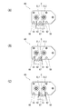
- FIG. 4 is a schematic diagram illustrating a state in which the shape of the first direction orthogonal to the plane where the length direction and the pitch direction of the lead wire intersect is corrected by the first correction jig provided in the correction device according to the present embodiment.
- FIG. 4A is a schematic diagram illustrating a state immediately before the electronic component is inserted into the first correction jig.
- FIG. 4B is a schematic view showing a state in which the first lead wire is in contact with the guide portion of the groove.
- FIG. 4C is a schematic view showing a state in which the first and second lead wires pass while the shape is corrected by coming into contact with the correction portion of the groove.
- FIG. 4D is a schematic diagram illustrating a state immediately after the shape of the lead wire in the first direction is corrected.
- the lead wire EL of the electronic component E has a first lead wire EL1 and a second lead wire EL2.
- Each of the first lead wire EL1 and the second lead wire EL2 has a distorted shape in a first direction orthogonal to the plane where the length direction and the pitch direction intersect (the front side of the paper in FIG. 4), and The shape in the pitch direction (left and right direction in FIG. 4) is distorted.
- the first lead wire EL ⁇ b> 1 that is held and rotated by the holding mechanism 24 is brought into contact with the guide portion 44 formed at the left end of the drawing in the drawing in the extending direction of the groove 41, and the correction portion 43.
- the second lead wire EL2 is similarly guided to the correction unit 43.
- the first lead wire EL1 and the second lead wire EL2 guided to the correction portion 43 pass through the groove 41 (and the first correction jig 40) while being corrected in shape by contacting the correction portion 43, respectively. .
- the first lead wire EL1 and the second lead wire EL2 are each distorted in shape in the first direction perpendicular to the plane where the length direction and the pitch direction intersect with each other by the first correction jig 40. Is corrected.
- FIG. 5 is an external perspective view of a second straightening jig provided in the straightening device according to the present embodiment.
- the second correction jig 60 is held by the holding mechanism 24 and is in contact with one side portion in the pitch direction of the lead wire EL that swings in the rotation direction of the rotating member 22.
- the contact portion 61 and the second contacted portion 62 with which the other side portion in the pitch direction of the lead wire EL held by the holding mechanism 24 and swinging in the rotation direction of the rotating member 22 is contacted are connected to the lead wire.
- the distance between the first contacted part 61 and the second contacted part 62 is equal to the pitch of the lead wires EL.
- the second correction jig 60 includes a first protrusion 66, a second protrusion 67, and a third protrusion 68 that are arranged in parallel with each other at an interval and protrude in the first direction.
- a first protrusion is disposed at one end in the parallel direction
- a second protrusion is disposed at the center in the parallel direction
- a third protrusion is disposed at the other end in the parallel direction.
- the first protrusion 66, the second protrusion 67, and the third protrusion 68 are arranged such that the parallel direction extends in the same direction as the left-right direction of the robot 10.
- the second correction jig 60 is attached to the base 29 attached to the robot arm 13a so as to be able to reciprocate in a first direction orthogonal to a plane where the length direction and the pitch direction of the lead wire EL intersect.
- the second correction jig 60 is disposed on the rear side of the first correction jig 40 in the rotation direction of the rotation member 22.
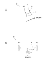
- FIG. 6 is a schematic view showing a state in which the shape of the lead wire in the pitch direction is corrected by the second correction jig provided in the correction device according to the present embodiment.
- FIG. 6A is a schematic diagram showing a state immediately before the shape of the lead wire of the electronic component is corrected by the second correction jig.
- FIG. 6B is a schematic diagram showing a state where the first lead wire is in contact with the first protrusion and the second lead wire is in contact with the second protrusion.
- FIG. 6C is a schematic diagram illustrating a state in which the first lead wire is in contact with the second protrusion and the second lead wire is in contact with the third protrusion.
- the first lead wire EL1 and the second lead wire EL2 that are held and rotated by the holding mechanism 24 are each shaped in a first direction orthogonal to the plane where the length direction and the pitch direction intersect by the first correction jig 40. After the distortion is corrected, it rotates to the position of the second correction jig 60 in the rotation direction.
- the second correction jig 60 does not hinder the rotation of the first lead wire EL1 and the second lead wire EL2 by the first protrusion 66, the second protrusion 67, and the third protrusion 68 as shown in FIG.
- the first lead EL1 is positioned between the first protrusion 66 and the second protrusion 67 when viewed from the front (that is, when viewed in the front-rear direction of the robot 10).
- the second correction jig 60 is moved from the back side to the front side of the drawing.
- the electronic component E held by the holding unit 26 is swung in the rotating direction of the rotating member 22. Specifically, first, as shown in FIG. 6B, the electronic component E is swung to the left, so that one side portion in the pitch direction of the first lead wire EL1 becomes the first protrusion 66. The one side portion in the pitch direction of the second lead wire EL ⁇ b> 2 is in contact with a part of the side surface of the second protrusion 67 on the side of the second protrusion 67, and the portion of the side surface of the second protrusion 67 on the side of the third protrusion 68. Abutted. Next, as shown in FIG.
- the electronic component E is swung to the right, so that the other side portion in the pitch direction of the first lead wire EL ⁇ b> 1 is the first side surface of the second protrusion 67.
- the other side portion in the pitch direction of the second lead wire EL ⁇ b> 2 is in contact with a part on the second protrusion 67 side on the side surface of the third protrusion 68. .
- the first contacted portion 61 with which one side portion in the pitch direction of the first lead wire EL1 contacts is configured as a part of the side surface of the first protrusion 66 on the second protrusion 67 side.
- the second contacted portion 62 with which the other side portion in the pitch direction of the first lead wire EL1 is in contact is configured as a part of the side surface of the second protrusion 67 on the first protrusion 66 side.
- the first contacted portion 61 with which one side portion in the pitch direction of the second lead wire EL2 is in contact is configured as a part of the side surface of the second protrusion 67 on the third protrusion 68 side. .
- abutted is comprised as a part by the side of the 2nd protrusion 67 side of the 3rd protrusion 68 side surface.
- the first lead wire EL1 and the second lead wire EL2 are each corrected in shape distortion in the pitch direction by the second correction jig 60.
- End effector 20b The end effector 20b indicated by a broken line in FIG. 2 may have a structure for holding a guide jig for guiding a lead wire of the electronic component E to a through hole drilled in the wiring board, for example.
- Other arbitrary structures may be provided.
- the correction device 30 according to the present embodiment can pass while the shape is corrected by the contact of the lead wire EL with the correction portions 43 of the pair of inner walls 42 and 42 of the first correction jig 40. As a result, the correction device 30 according to the present embodiment can easily correct the shape of the lead wire EL of the electronic component E with a simple structure.
- the correction device 30 can guide the lead wire EL to the correction unit 43 by the guide unit 44. As a result, the shape of the lead wire EL can be corrected more easily.
- the first correction jig 40 includes a pair of base bodies 45, 45 and a pair of base bodies 45, 45 such that the main surfaces of the pair of base bodies 45, 45 constitute a pair of inner walls 42, 42. Since the fixing members 48a to 48c for fixing the bodies 45 and 45 to each other are provided, the shape of the lead wire EL of the electronic component E can be corrected with a simple configuration. Further, since each member can be disassembled by removing the fixing members 48a to 48b, the maintainability can be improved.
- the first correction jig 40 is shaped by the rotating lead wire EL held by the holding device 21 and contacting the correction portion 43 of the groove 41. It is arranged to pass while being corrected. As a result, the robot 10 according to the present embodiment can easily correct the shape of the lead wire EL of the electronic component E with a simple structure.
- the holding device 21 includes the rotating member 22 and the holding mechanism 24 that is fixed so as to extend radially with respect to the rotating member 22, the holding device 24 is electronically connected to the holding mechanism 24 while rotating the rotating member 22.
- the component E can be held, and the shape of the lead wire EL can be corrected by the correction device 30. Therefore, the shape of the lead wire EL of the electronic component E can be corrected efficiently.
- the holding mechanism 24 has the eight holding mechanisms 24, the eight electronic components E are held by the correction device 30 while holding the electronic components E in the eight holding mechanisms 24 while rotating the rotating member 22.
- the shape of each of the lead wires EL can be corrected.
- the electronic device E held by each of the eight holding mechanisms 24 is mounted on a wiring board (not shown) while rotating the rotating member 22, and each of the lead wires EL of the eight electronic components E is corrected by the correction device 30.
- the shape can also be corrected. Therefore, it is possible to efficiently correct the shape of each of the lead wires EL of the eight electronic components E.
- the robot 10 further includes the second correction jig 60 in the correction device 30, so that the first correction jig 40 orthogonally intersects the plane where the length direction and the pitch direction of the lead wire EL intersect.
- the shape in the direction can be corrected, and the shape in the pitch direction of the lead wire EL can be corrected by the second correction jig 60.
- the robot 10 can correct the shape of the lead wire EL in the pitch direction by the second correction jig 60 having a simple structure including the first protrusion 66, the second protrusion 67, and the third protrusion 68. It becomes possible.
- FIG. 7 is a schematic view showing a state in which an abnormality in the shape of the lead wire is detected by a detection device provided in the robot.
- FIG. 7A is a schematic view when viewed along the direction of the light beam irradiated by the detection device, and
- FIG. 7B shows electrons along the length direction at the center in the pitch direction of the lead wire. It is the schematic when the state which cut
- the end effector 20a included in the robot 10 may further include a detection device 80 for detecting whether or not the shape of the lead wire EL is abnormal.
- the detecting device 80 has a projector 82 that irradiates a light beam R indicated by a broken line in the drawing onto a lead wire EL held and rotated by the holding mechanism 24.
- the detection device 80 further includes a light receiver 84 that receives the light beam R that is held by the holding mechanism 24 and emitted from the projector 82.
- the light projector 82 irradiates the light beam R along the tangential direction of the orbit of the lead wire EL held and rotated by the holding mechanism 24. As shown in FIG. 7, the projector 82 is disposed on the front side of the paper in FIG. 2, and the light receiver 84 is disposed on the back side of the paper in FIG.
- the detection device 80 can determine that there is no abnormality in the shape of the lead wire EL when the light beam R projected from the projector 82 is shielded by the lead wire EL. Further, the detection device 80 can determine that the shape of the lead wire EL is abnormal when the light beam R projected from the projector 82 is not shielded by the lead wire EL.
- the rotating device 22 is rotated, the electronic device E is held by each of the eight holding portions 26, and the lead wire EL is corrected by the first correction jig 40, and the lead wire is detected by the detection device 80.
- An abnormality in the shape of the EL can be detected.
- the detection device 80 may be disposed between the first correction jig 40 and the second correction jig 60 in the rotation direction of the rotary member 22, for example. Thereby, it is detected whether or not there is an abnormality in the shape of the lead wire EL with respect to the lead wire EL whose distortion in the first direction is corrected by the first correction jig 40, and only when the abnormality is detected, the second The distortion in the pitch direction can be corrected by swinging the lead wire EL at the position of the correction jig 60. That is, when no abnormality is detected in the lead wire EL by the detection device 80, it is not necessary to swing the lead wire EL at the position of the second correction jig 60, so that the shape of the lead wire EL is corrected more efficiently. It becomes possible to do.
- the detection device 80 shown in FIG. 7 shows a case of a transmission type detection device in which the light receiver 84 is disposed so as to face the projector 82 via a lead wire EL that is held by the holding mechanism 24 and rotates.
- the detection device 80 may be a reflective detection device in which the projector 82 and the light receiver 84 are arranged on the same side. In such a case, the detection device 80 can determine that there is no abnormality in the shape of the lead wire EL when the light beam R irradiated by the projector 82 is reflected by the lead wire EL and received by the light receiver 84. Further, the detection device 80 may determine that the shape of the lead wire EL is abnormal when the light beam R irradiated by the projector 82 does not hit the lead wire EL and is not reflected and received by the light receiver 84.
- the first correction jig 40 has a pair of base bodies 45, 45 and a pair of base bodies 45, 45 so that the main surfaces of the pair of base bodies 45, 45 constitute a pair of inner walls 42, 42.
- the present invention is not limited to this case.
- the first correction jig 40 is configured by one member formed in a substantially U shape when viewed in the extending direction of the groove 41, and does not have to include the fixing member 48.
- the groove 41 is constituted by a pair of inner walls 42 and 42 facing in the width direction when viewed in the extending direction, and a bottom wall.
- the first contact portion 61 and the second contact portion 62 of the second correction jig 60 are configured as the first protrusion 66, the second protrusion 67, and the third protrusion 68.
- the present invention is not limited to this.
- the first contacted part 61 and the second contacted part 62 of the second correction jig 60 have a width dimension that decreases toward the back side in the first direction when viewed from the front side of the robot 10. It may be configured as a V-shaped inner wall arranged in the above, or may be another structure.
- the correction device 30 includes the second correction jig 60 .
- the present invention is not limited to this, and the second correction jig 60 may not be provided.
- the pair of inner walls 42, 42 has been described with respect to the case where the guide portions 44 are provided at both ends in the extending direction. May be provided, or the guide portion 44 may not be provided.
- the lead wire EL is provided between the pair of inner walls 42 and 42 from the side where the guide part 44 is provided. It is preferable to insert.
- the lead wire EL is composed of the two lead wires of the first lead wire EL1 and the second lead wire EL2
- the present invention is not limited to this. That is, the lead wire EL may be composed of three or more lead wires EL.
- the second correction jig 60 may have four or more protrusions in order to correct the shape of the lead wire EL in the pitch direction.
- the end effector 20 a includes a holding device that does not include the rotating member 22 and has only the holding mechanism 24, and the end effector 20 b includes another holding device for holding the first correction jig 40. It may be.
- the first correction jig 40 has the lead wire EL that is relatively moved while being held by the holding device corrected the groove 41.
- the shape of the lead wire EL may be corrected by abutting on the correction portion 43 of the groove 41 in a rectilinear motion instead of a rotational motion.
- one of the electronic component E and the first correction jig 40 is fixed separately from the robot 10, and the other of the electronic component E and the first correction jig 40 is used as a holding device for the end effector 20a.
- the electronic component E and the first correction jig 40 may move relatively by being held and operated. Note that the electronic component E and the first correction jig 40 may be relatively moved manually without using the robot 10 (or in cooperation with the robot 10).
- the second correction jig 60 corrects the shape of the lead wire EL by contacting the lead wire EL held by the holding mechanism 24 and swinging in the rotation direction of the rotating member 22.
- the present invention is not limited to this.
- the end effector 20a has a holding device having only the holding mechanism 24 without having the rotating member 22, and the end effector 20b has another holding device for holding the second correction jig 60. It may be.
- the second correction jig 60 has the first lead EL that is held by the holding device and relatively swings. You may arrange
- one of the electronic component E and the second correction jig 60 is fixed separately from the robot 10, and the other of the electronic component E and the second correction jig 60 is a holding device for the end effector 20a.
- the electronic component E and the second correction jig 60 may swing relatively by being held and swinging. Note that the electronic component E and the second correction jig 60 may be relatively swung manually without using the robot 10 (or in cooperation with the robot 10).
Landscapes
- Engineering & Computer Science (AREA)
- Manufacturing & Machinery (AREA)
- Microelectronics & Electronic Packaging (AREA)
- Robotics (AREA)
- Mechanical Engineering (AREA)
- Operations Research (AREA)
- Manipulator (AREA)
- Supply And Installment Of Electrical Components (AREA)
- Container, Conveyance, Adherence, Positioning, Of Wafer (AREA)
Abstract
電子部品のリード線の形状を矯正するための矯正装置であって、溝を有する第1矯正冶具を備えており、前記溝は、前記リード線の直径寸法に応じた距離だけ幅方向において対向する一対の内壁を有しており、前記一対の内壁は、それぞれ、前記幅方向に直交する深さ方向に見て、前記幅方向及び前記深さ方向に直交する延在方向において互いに平行して直線状に延在する矯正部を有していることを特徴とする。
Description
本発明は、矯正装置及びそれを備えるロボットに関する。
従来から、電子部品のリード線の形状を矯正するための矯正装置が知られている。このような矯正装置として、例えば、特許文献1で提案されているリード矯正部及び治具がある。
特許文献1では、ロボットハンドに設けられるリード矯正部が切欠き溝を有している。リード矯正部は、治具によって先端が固定された状態のリード線を前記切欠き溝により噛合することで、リード線の曲がりを矯正する。
ところで、特許文献1は、リード矯正部及び治具の双方を用いてリード線の形状を矯正しているので、複雑な構造であるという問題があった。また、リード線の先端を治具で固定してから当該リード線をリード矯正部の切欠き溝により噛合しなければならいので、リード線を矯正する際の手順が煩雑であるという問題もあった。
そこで、本発明は、簡単な構造で容易に電子部品のリード線の形状を矯正することが可能な、矯正装置及びそれを備えるロボットを提供することを目的とする。
前記課題を解決するために、本発明に係る矯正装置は、電子部品のリード線の形状を矯正するための矯正装置であって、溝を有する第1矯正冶具を備えており、前記溝は、前記リード線の直径寸法に応じた距離だけ幅方向において対向する一対の内壁を有しており、前記一対の内壁は、それぞれ、前記幅方向に直交する深さ方向に見て、前記幅方向及び前記深さ方向に直交する延在方向において互いに平行して直線状に延在する矯正部を有していることを特徴とする。
上記構成によれば、リード線が一対の内壁の矯正部に当接することで形状を矯正されながら通過することができる。その結果、本発明に係る矯正装置は、簡単な構造で容易に電子部品のリード線の形状を矯正することができる。
前記一対の内壁は、それぞれ、前記延在方向における両端のうちの少なくとも一方に、前記延在方向の中央部に向かうに連れて前記幅方向における間隔が狭くなるガイド部を有している。
上記構成によれば、ガイド部によって矯正部にリード線を案内することができる。これにより、いっそう容易にリード線の形状を矯正することが可能となる。
第1矯正治具は、各々が板状に形成された一対のベース体と、前記一対のベース体の主面が前記一対の内壁を構成するように、前記一対のベース体を互いに固定するための固定部材と、を備えていてもよい。
上記構成によれば、簡単な構成の第1矯正治具で電子部品のリード線の形状を矯正することができ、且つ、メンテナンス性を向上させることが可能となる。
前記課題を解決するために、本発明に係るロボットは、上記いずれかの矯正装置を備えるロボットであって、ロボットアームと、前記ロボットアームに取り付けられるエンドエフェクタと、を備えており、前記エンドエフェクタは、前記電子部品を保持するための保持装置と、前記矯正装置と、を有しており、前記第1矯正冶具は、前記保持装置に保持されて相対的に移動する前記リード線が前記溝の矯正部に当接することで形状を矯正されながら通過するように配置されていることを特徴とする。
上記構成によれば、保持装置に保持されて相対的に移動するリード線が溝の矯正部に当接することで形状を矯正されながら通過するように配置されている第1矯正治具によって、簡単な構造で容易に電子部品のリード線の形状を矯正することができる、ロボットを提供することが可能となる。
前記保持装置は、前記ロボットアームに対して回転可能に取り付けられる回転部材と、前記回転部材に対して前記回転部材の回転軸を中心として放射状に延びるよう固定される保持機構と、を有しており、前記第1矯正治具は、前記保持機構に保持されて回転する前記リード線が前記溝の矯正部に当接することで形状を矯正されながら通過するように配置されていてもよい。
上記構成によれば、回転部材を回転させつつ保持機構に電子部品を保持させることができ、且つ、矯正装置によって電子部品のリード線の形状を矯正することができる。したがって、電子部品のリード線の形状を効率よく矯正することが可能となる。
前記保持装置は、前記回転部材の回転方向に互いに間隔を設けて前記保持機構を複数有しており、且つ、前記回転部材を回転させつつ前記複数の保持機構それぞれに前記電子部品を保持させることで前記電子部品を複数個保持してもよい。
上記構成によれば、回転部材を回転させつつ複数の保持機構それぞれに電子部品を保持させながら、矯正装置によって複数の電子部品のリード線それぞれの形状を矯正することができる。したがって、複数の電子部品のリード線それぞれの形状を効率よく矯正することが可能となる。
前記矯正装置は、第2矯正治具をさらに備えており、前記第2矯正治具は、前記保持装置に保持されて相対的に揺動する前記リード線のピッチ方向における一方側部分が当接される第1被当接部と、前記保持装置に保持されて相対的に揺動する前記リード線のピッチ方向における他方側部分が当接される第2被当接部と、を前記リード線それぞれに対して有しており、前記第1被当接部と前記第2被当接部との間隔は前記リード線のピッチに等しくてもよい。
上記構成によれば、第1矯正冶具によってリード線の長さ方向とピッチ方向とが交わる平面に直交する第1方向における形状を矯正することができ、且つ、第2矯正冶具によってリード線のピッチ方向における形状を矯正することが可能となる。
前記リード線は、第1リード線と第2リード線とを有しており、前記第2矯正治具は、前記リード線の長さ方向とピッチ方向とが交わる平面に直交する第1方向に往復運動可能であり、各々が互いに間隔を空けて並列され、且つ、各々が前記第1方向において突出する第1突部、第2突部及び第3突部を備えており、並列方向の一方端に前記第1突部が配置されており、前記並列方向の中央に前記第2突部が配置されており、且つ、前記並列方向の他方端に前記第3突部が配置されており、前記第1リード線のピッチ方向における一方側部分が当接される第1被当接部が、前記第1突部の側面の前記第2突部側の一部として構成されており、前記第1リード線のピッチ方向における他方側部分が当接される第2被当接部が、前記第2突部の側面の前記第1突部側の一部として構成されており、前記第2リード線のピッチ方向における一方側部分が当接される第1被当接部が、前記第2突部の側面の前記第3突部側の一部として構成されており、且つ、前記第2リード線のピッチ方向における他方側部分が当接される第2被当接部が、前記第3突部の側面の前記第2突部側の一部として構成されていてもよい。
上記構成によれば、簡単な構成の第2矯正冶具によってリード線のピッチ方向における形状を容易に矯正することが可能となる。
前記エンドエフェクタは、前記リード線の形状に異常があるか否かを検出するための検出装置をさらに有していてもよい。
上記構成によれば、検出装置によって、リード線に異常があった場合にそれを検出することができる。
前記検出装置は、前記保持装置に保持されて相対的に移動する前記リード線に光線を照射する投光器と、前記投光器から照射された光線を受光する受光器と、を有していてもよい。
上記構成によれば、矯正装置によってリード線の形状を矯正することができ、且つ、検出装置によってリード線に異常があった場合にそれを検出することができる。
本発明によれば、簡単な構造で容易に電子部品のリード線の形状を矯正することが可能な、矯正治具及びそれを備えるロボットを提供することができる。
以下、本発明の一実施形態に係る矯正装置及びそれを備えるロボットについて、図面を参照して説明する。なお、本実施形態によって本発明が限定されるものではない。また、以下では、全ての図を通じて、同一又は相当する要素には同一の参照符号を付して、その重複する説明を省略する。
(ロボット10)
図1は、本実施形態に係る矯正装置及びそれを備えるロボットの全体構造を示す概略図である。図1に示すように、本実施形態に係る矯正装置30は、ロボット10に備えられている。ロボット10は、台車に固定された基台12と、基台12に支持された一対のロボットアーム13a、13bと、基台12内に収納された図中破線で示す制御装置14と、を備えている。また、ロボット10は、ロボットアーム13aに取り付けられるエンドエフェクタ20aと、ロボットアーム13bに取り付けられるエンドエフェクタ20bと、をさらに備えている。
図1は、本実施形態に係る矯正装置及びそれを備えるロボットの全体構造を示す概略図である。図1に示すように、本実施形態に係る矯正装置30は、ロボット10に備えられている。ロボット10は、台車に固定された基台12と、基台12に支持された一対のロボットアーム13a、13bと、基台12内に収納された図中破線で示す制御装置14と、を備えている。また、ロボット10は、ロボットアーム13aに取り付けられるエンドエフェクタ20aと、ロボットアーム13bに取り付けられるエンドエフェクタ20bと、をさらに備えている。
ロボット10は、人一人分に相当する限られたスペース(例えば610mm×620mm)に設置することができる。以下では、一対のロボットアームを広げた方向を左右方向と称し、基軸の軸心に平行な方向を上下方向と称し、且つ、左右方向及び上下方向に直交する方向を前後方向と称する。本実施形態のロボット10は、配線基板(図示せず)の実装現場に適用され、電子部品を保持して搬送しながら配線基板に実装する作業を行う。
(一対のロボットアーム13a、13b)
一対のロボットアーム13a、13bは、それぞれ、基台12に対して移動可能に構成された水平多関節型のロボットアームである。一対のロボットアーム13a、13bは、それぞれ、独立して動作したり、互いに関連して動作したりすることができる。なお、ロボットアーム13bは、ロボットアーム13aと同様の構成を有している。したがって、ここではロボットアーム13aについてのみ説明し、ロボットアーム13bの同様となる説明は繰り返さない。
一対のロボットアーム13a、13bは、それぞれ、基台12に対して移動可能に構成された水平多関節型のロボットアームである。一対のロボットアーム13a、13bは、それぞれ、独立して動作したり、互いに関連して動作したりすることができる。なお、ロボットアーム13bは、ロボットアーム13aと同様の構成を有している。したがって、ここではロボットアーム13aについてのみ説明し、ロボットアーム13bの同様となる説明は繰り返さない。
ロボットアーム13aは、関節J1~J4を有している。そして、ロボットアーム13aには、関節J1~J4に対応付けられるように、駆動用のサーボモータ(図示せず)が設けられている。ロボットアーム13aは、リンク15と、リスト17とを有している。リンク15は、本例では、第1リンク15a及び第2リンク15bを有している。第1リンク15aは、基台12の上面に固定された基軸16と回転関節J1により連結され、基軸16の軸心を通る回転軸L1まわりに回動可能である。第2リンク15bは、第1リンク15aの先端と回転関節J2により連結され、第1リンク15aの先端に規定された回転軸L2まわりに回動可能である。
リスト17は、エンドエフェクタ20aが取り付けられるメカニカルインターフェース19を有しており、第2リンク15bの先端と直動関節J3及び回転関節J4を介して連結されている。リスト17は、直動関節J3によって、第2リンク15bに対し昇降移動可能である。リスト17は、回転関節J4によって、第2リンク15bに対し垂直な回転軸L3まわりに回動可能である。
ロボットアーム13aの第1リンク15aの回転軸L1と、ロボットアーム13bの第1リンク15aの回転軸L1とは同一直線上にあり、ロボットアーム13aの第1リンク15aとロボットアーム13bの第1リンク15aとは上下に高低差を設けて配置されている。
(エンドエフェクタ20a)
図2は、ロボットが備える保持装置に複数の電子部品を保持させた状態を示す図である。エンドエフェクタ20aは、複数の電子部品Eを保持するための保持装置21と、電子部品Eのリード線ELの形状を矯正するための矯正装置30と、を有している。
図2は、ロボットが備える保持装置に複数の電子部品を保持させた状態を示す図である。エンドエフェクタ20aは、複数の電子部品Eを保持するための保持装置21と、電子部品Eのリード線ELの形状を矯正するための矯正装置30と、を有している。
(保持装置21)
保持装置21は、ロボットアーム13aに対して回転可能に取り付けられる回転部材22と、回転部材22に対して当該回転部材22の回転軸23を中心として放射状に延びるよう固定される8つの保持機構24と、を有している。
保持装置21は、ロボットアーム13aに対して回転可能に取り付けられる回転部材22と、回転部材22に対して当該回転部材22の回転軸23を中心として放射状に延びるよう固定される8つの保持機構24と、を有している。
回転部材22は、円板状に形成されている。回転部材22は、その厚み方向とロボット10の前後方向とが一致するように基部29を介してロボットアーム13aに取り付けられている。回転部材22は、図示しないモータによって回転軸23を中心に回転可能である。
8本の保持機構24は、回転部材22の回転方向に互いに等間隔で(互いに間隔を設けて)配置されている。8本の保持機構24は、互いに同じ構造を有する。したがって、図2では見た目の煩雑さを避けるため、最も左側に位置する保持機構24についてのみ詳細に符号を付して説明し、残り7本の保持機構24についての詳細な符号は適宜省略しその説明は繰り返さない。
保持機構24は、回転部材22の回転軸23を中心として放射状に延びる径方向延在部25と、径方向延在部25の先端部に設けられる保持部26と、を有している。保持部26は、両側から挟み込むように挟持して電子部品Eを保持する既知の構造である。しかし、この場合に限定されず、保持部26は、負圧を利用して吸着することにより電子部品Eを保持する既知の構造であってもよいし、或いは、その他の態様で電子部品Eを保持する構造であってもよい。
(矯正装置30)
本実施形態に係る矯正装置30は、保持機構24に保持されて回転するリード線ELの軌道の図2において右上部分に沿って配置される第1矯正冶具40と、同軌道の図2において最も上方部分に沿って配置される第2矯正冶具60と、を備えている。
本実施形態に係る矯正装置30は、保持機構24に保持されて回転するリード線ELの軌道の図2において右上部分に沿って配置される第1矯正冶具40と、同軌道の図2において最も上方部分に沿って配置される第2矯正冶具60と、を備えている。
(第1矯正冶具40)
図3は、本実施形態に係る矯正装置が備える第1矯正冶具の外観斜視図である。図3に示すように、第1矯正冶具40は、溝41を有している。溝41は、リード線ELの直径寸法に応じた距離だけ幅方向において対向する一対の内壁42、42を有している。一対の内壁42、42は、それぞれ、幅方向に直交する深さ方向に見て、幅方向及び深さ方向に直交する延在方向において互いに平行して直線状に延在する矯正部43を有している。なお、溝41は、延在方向における両端それぞれが開放されている。
図3は、本実施形態に係る矯正装置が備える第1矯正冶具の外観斜視図である。図3に示すように、第1矯正冶具40は、溝41を有している。溝41は、リード線ELの直径寸法に応じた距離だけ幅方向において対向する一対の内壁42、42を有している。一対の内壁42、42は、それぞれ、幅方向に直交する深さ方向に見て、幅方向及び深さ方向に直交する延在方向において互いに平行して直線状に延在する矯正部43を有している。なお、溝41は、延在方向における両端それぞれが開放されている。
一対の内壁42、42は、それぞれ、延在方向における両端に、延在方向の中央部に向かうに連れて幅方向における間隔が狭くなるガイド部44をさらに有している。
第1矯正冶具40は、各々が板状に形成された一対のベース体45、45と、一対のベース体45、45の主面が一対の内壁42、42を構成するように、一対のベース体45、45を互いに固定するための固定部材48a、48b、48cと、を備えている。また、上記のように一対のベース体45、45を厚み方向に対向させて固定することで、上記したガイド部44が構成される。
第1矯正治具40は、保持機構24に保持されて回転するリード線ELが溝41の矯正部43に当接することで形状を矯正されながら通過するように配置されている。
なお、一対のベース体45、45は、それぞれ、溝41の深さ方向に見て図3において略上方に突出しつつ湾曲する端面を有している。一対のベース体45、45がこのような形状を有していることで、第1矯正治具40は、小型化を図りつつ、保持機構24に保持されて回転するリード線ELの軌道の一部に沿って溝41が延在するように設置され得る。
図4は、本実施形態に係る矯正装置が備える第1矯正冶具によって、リード線の長さ方向とピッチ方向とが交わる平面に直交する第1方向の形状を矯正する様子を示す概略図である。図4(A)は、電子部品が第1矯正治具に挿入される直前の状態を示す概略図である。図4(B)は、第1リード線が溝のガイド部に当接された状態を示す概略図である。図4(C)は、第1及び第2リード線が溝の矯正部に当接することで形状を矯正されながら通過する様子を示す概略図である。図4(D)は、リード線の第1方向の形状が矯正された直後の状態を示す概略図である。
図4に示すように、本実施形態に係る電子部品Eのリード線ELは、第1リード線EL1及び第2リード線EL2を有している。第1リード線EL1及び第2リード線EL2は、それぞれ、長さ方向とピッチ方向とが交わる平面に直交する第1方向(図4において紙面の奥手前方向)における形状が歪んでおり、且つ、ピッチ方向(図4において紙面の左右方向)における形状が歪んでいる。
図4に示すように、保持機構24に保持されて回転する第1リード線EL1は、溝41の延在方向における図中紙面左端に形成されたガイド部44に当接されて、矯正部43へと案内される。そのあと、第2リード線EL2についても同様に矯正部43へと案内される。矯正部43へと案内された第1リード線EL1及び第2リード線EL2は、それぞれ、矯正部43に当接することで形状を矯正されながら溝41(及び第1矯正治具40)を通過する。
このとき、詳細には、第1リード線EL1及び第2リード線EL2は、それぞれ、第1矯正治具40によって、長さ方向とピッチ方向とが交わる平面に直交する第1方向における形状の歪みが矯正される。
(第2矯正治具60)
図5は、本実施形態に係る矯正装置が備える第2矯正冶具の外観斜視図である。図5に示すように、第2矯正治具60は、保持機構24に保持されて回転部材22の回転方向に揺動するリード線ELのピッチ方向における一方側部分が当接される第1被当接部61と、保持機構24に保持されて回転部材22の回転方向に揺動するリード線ELのピッチ方向における他方側部分が当接される第2被当接部62と、をリード線ELそれぞれ(すなわち、第1リード線EL1及び第2リード線EL2それぞれ)に対して有している。第1被当接部61と第2被当接部62との間隔はリード線ELのピッチに等しい。
図5は、本実施形態に係る矯正装置が備える第2矯正冶具の外観斜視図である。図5に示すように、第2矯正治具60は、保持機構24に保持されて回転部材22の回転方向に揺動するリード線ELのピッチ方向における一方側部分が当接される第1被当接部61と、保持機構24に保持されて回転部材22の回転方向に揺動するリード線ELのピッチ方向における他方側部分が当接される第2被当接部62と、をリード線ELそれぞれ(すなわち、第1リード線EL1及び第2リード線EL2それぞれ)に対して有している。第1被当接部61と第2被当接部62との間隔はリード線ELのピッチに等しい。
第2矯正治具60は、各々が互いに間隔を空けて並列され、且つ、各々が第1方向において突出する第1突部66、第2突部67及び第3突部68を備えている。並列方向の一方端に第1突部が配置されており、並列方向の中央に第2突部が配置されており、且つ、並列方向の他方端に第3突部が配置されている。なお、本実施形態において、第1突部66、第2突部67及び第3突部68は、その並列方向がロボット10の左右方向と同じ方向に延びるように配置される。
第2矯正治具60は、ロボットアーム13aに取り付けられる基部29に、リード線ELの長さ方向とピッチ方向とが交わる平面に直交する第1方向に往復運動可能であるように取り付けられる。また、第2矯正治具60は、回転部材22の回転方向において第1矯正治具40の後側に配置されている。
図6は、本実施形態に係る矯正装置が備える第2矯正冶具によって、リード線のピッチ方向の形状を矯正する様子を示す概略図である。図6(A)は、電子部品のリード線の形状が第2矯正治具によりを矯正される直前の状態を示す概略図である。図6(B)は、第1突部に第1リード線が当接しており、且つ、第2突部に第2リード線が当接している状態を示す概略図である。図6(C)は、第2突部に第1リード線が当接しており、且つ、第3突部に第2リード線が当接している状態を示す概略図である。
保持機構24に保持されて回転する第1リード線EL1及び第2リード線EL2は、それぞれ、第1矯正治具40によって、長さ方向とピッチ方向とが交わる平面に直交する第1方向における形状の歪みが矯正されてから、回転方向における第2矯正治具60の位置まで回転してくる。
このとき、第2矯正治具60は、第1突部66、第2突部67及び第3突部68により第1リード線EL1及び第2リード線EL2の回転を妨げないように、図6において紙面奥側に位置している。そして、図6(A)に示すように、正面視において(すなわち、ロボット10の前後方向に見て)、第1突部66と第2突部67との間に第1リード線EL1が位置し、且つ、第2突部67と第3突部68との間に第2リード線EL2が位置した状態で、第2矯正治具60が紙面の奥側から手前側に移動される。
この状態にされたあと、保持部26に保持される電子部品Eは、回転部材22の回転方向に揺動される。具体的には、まず、図6(B)に示すように、電子部品Eが左側に揺動されることで、第1リード線EL1のピッチ方向における一方側部分が、第1突部66の側面の第2突部67側の一部に当接され、且つ、第2リード線EL2のピッチ方向における一方側部分が、第2突部67の側面の第3突部68側の一部に当接される。次に、図6(C)に示すように、電子部品Eが右側に揺動されることで、第1リード線EL1のピッチ方向における他方側部分が、第2突部67の側面の第1突部66側の一部に当接され、且つ、第2リード線EL2のピッチ方向における他方側部分が、第3突部68の側面の第2突部67側の一部に当接される。
上記のように、第1リード線EL1のピッチ方向における一方側部分が当接される第1被当接部61が、第1突部66の側面の第2突部67側の一部として構成されている。また、第1リード線EL1のピッチ方向における他方側部分が当接される第2被当接部62が、第2突部67の側面の第1突部66側の一部として構成されている。さらに、第2リード線EL2のピッチ方向における一方側部分が当接される第1被当接部61が、第2突部67の側面の第3突部68側の一部として構成されている。そして、第2リード線EL2のピッチ方向における他方側部分が当接される第2被当接部62が、第3突部68の側面の第2突部67側の一部として構成されている。これにより、第1リード線EL1及び第2リード線EL2は、それぞれ、第2矯正治具60によって、ピッチ方向における形状の歪みが矯正される。
(エンドエフェクタ20b)
図2において破線で示されるエンドエフェクタ20bは、例えば、電子部品Eのリード線を配線基板に穿設されたスルーホールに案内するためのガイド冶具を保持する構造を有してもよいし、或いは、その他の任意の構造を有してもよい。
図2において破線で示されるエンドエフェクタ20bは、例えば、電子部品Eのリード線を配線基板に穿設されたスルーホールに案内するためのガイド冶具を保持する構造を有してもよいし、或いは、その他の任意の構造を有してもよい。
(効果)
本実施形態に係る矯正装置30は、リード線ELが第1矯正治具40の一対の内壁42、42の矯正部43に当接することで形状を矯正されながら通過することができる。その結果、本実施形態に係る矯正装置30は、簡単な構造で容易に電子部品Eのリード線ELの形状を矯正することができる。
本実施形態に係る矯正装置30は、リード線ELが第1矯正治具40の一対の内壁42、42の矯正部43に当接することで形状を矯正されながら通過することができる。その結果、本実施形態に係る矯正装置30は、簡単な構造で容易に電子部品Eのリード線ELの形状を矯正することができる。
また、本実施形態に係る矯正装置30は、ガイド部44によって矯正部43にリード線ELを案内することができる。これにより、いっそう容易にリード線ELの形状を矯正することが可能となる。
さらに、本実施形態では、第1矯正治具40は、一対のベース体45、45と、一対のベース体45、45の主面が一対の内壁42、42を構成するように、一対のベース体45、45を互いに固定するための固定部材48a~48cと、を備えているので、簡単な構成で電子部品Eのリード線ELの形状を矯正することができる。また、固定部材48a~48bを取り外すことで各部材を分解できるので、メンテナンス性を向上させることが可能となる。
そして、本実施形態に係る矯正装置30を備えるロボット10では、第1矯正治具40が、保持装置21に保持されて回転するリード線ELが溝41の矯正部43に当接することで形状を矯正されながら通過するように配置されている。その結果、本実施形態に係るロボット10は、簡単な構造で容易に電子部品Eのリード線ELの形状を矯正することができる。
また、保持装置21が、回転部材22と、当該回転部材22に対して放射状に延びるように固定される保持機構24とを有しているので、回転部材22を回転させつつ保持機構24に電子部品Eを保持させることができ、且つ、矯正装置30によってリード線ELの形状を矯正することができる。したがって、電子部品Eのリード線ELの形状を効率よく矯正することが可能となる。
さらに、保持機構24が、8つの保持機構24を有しているので、回転部材22を回転させつつ8つの保持機構24それぞれに電子部品Eを保持させながら、矯正装置30によって8つの電子部品Eのリード線ELそれぞれの形状を矯正することができる。また、回転部材22を回転させつつ8つの保持機構24それぞれに保持された電子部品Eを配線基板(図示せず)に実装させながら、矯正装置30によって8つの電子部品Eのリード線ELそれぞれの形状を矯正することもできる。したがって、8つの電子部品Eのリード線ELそれぞれの形状を効率よく矯正することが可能となる。
また、前記ロボット10は、矯正装置30が第2矯正治具60をさらに備えていることで、第1矯正冶具40によってリード線ELの長さ方向とピッチ方向とが交わる平面に直交する第1方向における形状を矯正することができ、且つ、第2矯正冶具60によってリード線ELのピッチ方向における形状を矯正することが可能となる。
さらに、前記ロボット10は、第1突部66、第2突部67及び第3突部68を有する簡単な構造の第2矯正治具60によってリード線ELのピッチ方向における形状を矯正することが可能となる。
(変形例)
上記説明から、当業者にとっては、本発明の多くの改良や他の実施形態が明らかである。したがって、上記説明は、例示としてのみ解釈されるべきであり、本発明を実行する最良の態様を当業者に教示する目的で提供されたものである。本発明の精神を逸脱することなく、その構造及び/又は機能の詳細を実質的に変更できる。
上記説明から、当業者にとっては、本発明の多くの改良や他の実施形態が明らかである。したがって、上記説明は、例示としてのみ解釈されるべきであり、本発明を実行する最良の態様を当業者に教示する目的で提供されたものである。本発明の精神を逸脱することなく、その構造及び/又は機能の詳細を実質的に変更できる。
図7は、ロボットが備える検出装置によって、リード線の形状の異常を検出する様子を示す概略図である。図7(A)が、検出装置によって照射される光線の方向に沿って見たときの概略図であり、図7(B)が、リード線のピッチ方向における中央で長さ方向に沿って電子部品を切断した状態を回転方向に沿って見たときの概略図である。図7に示すように、ロボット10が備えるエンドエフェクタ20aは、リード線ELの形状に異常があるか否かを検出するための検出装置80をさらに有していてもよい。
検出装置80は、保持機構24に保持されて回転するリード線ELに図中破線で示す光線Rを照射する投光器82を有している。また、検出装置80は、保持機構24に保持されて、投光器82から照射された光線Rを受光する受光器84をさらに有している。投光器82は、保持機構24に保持されて回転するリード線ELの軌道の接線方向に沿って光線Rを照射する。図7に示すように、投光器82が図2における紙面手前側に配置されており、受光器84が図2における紙面奥側に配置されている。
上記した構成を有することで、検出装置80は、投光器82から投光される光線Rがリード線ELに遮光されたとき、リード線ELの形状に異常がないと判定することができる。また、検出装置80は、投光器82から投光される光線Rがリード線ELに遮光されないとき、リード線ELの形状に異常があると判定することができる。
このとき、回転部材22を回転させつつ8つの保持部26それぞれに電子部品Eを保持させながら、且つ、第1矯正治具40でリード線ELの形状を矯正しつつ、検出装置80でリード線ELの形状の異常を検出することができる。
検出装置80は、例えば、回転部材22の回転方向において、第1矯正治具40と第2矯正治具60との間に配置されてもよい。これにより、第1矯正治具40で上記第1方向における歪みが矯正されたリード線ELにつき、リード線ELの形状に異常がない否かを検出し、異常が検出された場合のみ、第2矯正治具60の位置でリード線ELを揺動させてピッチ方向における歪みを矯正することができる。すなわち、検出装置80でリード線ELの異常が検出されなかった場合、第2矯正治具60の位置でリード線ELを揺動させる必要がなくなるので、いっそう効率的にリード線ELの形状を矯正することが可能となる。
なお、図7に示す検出装置80は、受光器84が保持機構24に保持されて回転するリード線ELを介して投光器82と対向するように配置されている透過型の検出装置の場合を示してあるが、これに限定されない。例えば、検出装置80は、投光器82と受光器84とが同じ側に配置される反射型の検出装置であってもよい。このような場合、検出装置80は、投光器82で照射された光線Rがリード線ELに当たって反射し受光器84で受光された場合にリード線ELの形状に異常がないと判定することができる。また、検出装置80は、投光器82で照射された光線Rがリード線ELに当たらずに反射せず受光器84で受光されない場合にリード線ELの形状に異常があると判定してもよい。
上記実施形態では、第1矯正治具40は、一対のベース体45、45と、一対のベース体45、45の主面が一対の内壁42、42を構成するように、一対のベース体45、45を互いに固定するための固定部材48と、を有する場合について説明したが、これに限定されない。例えば、第1矯正治具40は、溝41の延在方向に見て略U字状に形成された1つの部材により構成されており、固定部材48を有していなくてもよい。このとき、溝41は、延在方向に見て幅方向に対向する一対の内壁42、42と、底壁とにより構成されている。
上記実施形態では、保持機構24が8つ設けられる場合について説明したが、これに限定されない。すなわち、保持機構24は、1つ以上7つ以下設けられてもよいし、或いは、9つ以上設けられてもよい。
上記実施形態では、第2矯正治具60の第1被当接部61及び第2被当接部62は、第1突部66、第2突部67及び第3突部68として構成されている場合について説明したが、これに限定されない。例えば、第2矯正治具60の第1被当接部61及び第2被当接部62は、ロボット10の前側から見て第1方向の奥側に向かうに連れて幅寸法が小さくなるように配置されたV字状の内壁として構成されていてもよいし、或いは、その他の構造であってもよい。
上記実施形態では、矯正装置30が第2矯正治具60を備える場合について説明したが、これに限定されず、第2矯正治具60を備えなくてもよい。
上記実施形態では、一対の内壁42、42は、それぞれ、延在方向における両端にガイド部44を備える場合について説明したが、これに限定されず、延在方向における両端の少なくとも一方にガイド部44を備えていてもよいし、或いは、ガイド部44を備えていなくてもよい。なお、一対の内壁42、42が延在方向における両端の一方のみにガイド部44を備えている場合、ガイド部44が備えられている側から一対の内壁42、42の間にリード線ELを挿入させることが好ましい。
上記実施形態では、リード線ELが第1リード線EL1と第2リード線EL2の2つのリード線で構成されている場合を説明したが、これに限定されない。すなわい、リード線ELは、3つ以上のリード線ELで構成されていてもよい。このような場合、第2矯正治具60は、リード線ELのピッチ方向における形状を矯正するために、4つ以上の突部を有していてもよい。
上記実施形態では、保持機構24に保持されて回転するリード線ELが溝41の矯正部43に当接することで形状を矯正されながら通過する場合を説明したが、これに限定されない。例えば、エンドエフェクタ20aが回転部材22を有さずに保持機構24のみを有する保持装置を備えており、且つ、エンドエフェクタ20bが第1矯正治具40を保持するための他の保持装置を備えていてもよい。
このような構造によれば、ロボットアーム13a、13bのうちの少なくとも一方を動作させることで、第1矯正冶具40は、保持装置に保持されて相対的に移動するリード線ELが溝41の矯正部43に当接することで形状を矯正されながら通過するように配置されていてもよい。このとき、例えば、リード線ELは、回転運動ではなく直進運動で、溝41の矯正部43に当接することで形状を矯正されてもよい。
また、例えば、電子部品E及び第1矯正治具40の一方がロボット10とは別個に固定されており、且つ、電子部品E及び第1矯正治具40の他方がエンドエフェクタ20aの保持装置に保持されて動作することで、電子部品Eと第1矯正治具40とが相対的に移動してもよい。なお、ロボット10を用いずに(又はロボット10と協働して)人手により電子部品Eと第1矯正治具40とが相対的に移動されてもよい。
上記実施形態では、第2矯正治具60は、保持機構24に保持されて回転部材22の回転方向に揺動するリード線ELを当接されることで、当該リード線ELの形状を矯正する場合について説明したが、これに限定されない。例えば、エンドエフェクタ20aが回転部材22を有さずに保持機構24のみを有する保持装置を備えており、且つ、エンドエフェクタ20bが第2矯正治具60を保持するための他の保持装置を備えていてもよい。
このような構造によれば、ロボットアーム13a、13bのうちの少なくとも一方を揺動させることで、第2矯正冶具60は、保持装置に保持されて相対的に揺動するリード線ELが第1被当接部61及び第2被当接部62に当接されることで形状を矯正されるように配置されていてもよい。このとき、例えば、リード線ELは、回転運動ではなく直進運動で、第1被当接部61及び第2被当接部62に当接することで形状を矯正されてもよい。
また、例えば、電子部品E及び第2矯正治具60の一方がロボット10とは別個に固定されており、且つ、電子部品E及び第2矯正治具60の他方がエンドエフェクタ20aの保持装置に保持されて揺動することで、電子部品Eと第2矯正治具60とが相対的に揺動してもよい。なお、ロボット10を用いずに(又はロボット10と協働して)人手により電子部品Eと第2矯正治具60とが相対的に揺動されてもよい。
10 ロボット
12 基台
13 ロボットアーム
15 リンク
17 リスト
20 エンドエフェクタ
21 保持装置
22 回転部材
23 回転軸
24 保持機構
25 径方向延在部
26 保持部
29 基部
30 矯正装置
40 第1矯正冶具
41 溝
42 内壁
43 矯正部
44 ガイド部
45 ベース体
48 固定部材
60 第2矯正治具
61 第1被当接部
62 第2被当接部
66 第1突部
67 第2突部
68 第3突部
80 検出装置
82 投光器
84 受光器
E 電子部品
EL リード線
R 光線
12 基台
13 ロボットアーム
15 リンク
17 リスト
20 エンドエフェクタ
21 保持装置
22 回転部材
23 回転軸
24 保持機構
25 径方向延在部
26 保持部
29 基部
30 矯正装置
40 第1矯正冶具
41 溝
42 内壁
43 矯正部
44 ガイド部
45 ベース体
48 固定部材
60 第2矯正治具
61 第1被当接部
62 第2被当接部
66 第1突部
67 第2突部
68 第3突部
80 検出装置
82 投光器
84 受光器
E 電子部品
EL リード線
R 光線
Claims (10)
- 電子部品のリード線の形状を矯正するための矯正装置であって、
溝を有する第1矯正冶具を備えており、
前記溝は、前記リード線の直径寸法に応じた距離だけ幅方向において対向する一対の内壁を有しており、
前記一対の内壁は、それぞれ、前記幅方向に直交する深さ方向に見て、前記幅方向及び前記深さ方向に直交する延在方向において互いに平行して直線状に延在する矯正部を有していることを特徴とする、矯正装置。 - 前記一対の内壁は、それぞれ、前記延在方向における両端のうちの少なくとも一方に、前記延在方向の中央部に向かうに連れて前記幅方向における間隔が狭くなるガイド部を有している、請求項1に記載の矯正装置。
- 前記第1矯正治具は、
各々が板状に形成された一対のベース体と、
前記一対のベース体の主面が前記一対の内壁を構成するように、前記一対のベース体を互いに固定するための固定部材と、を有している、請求項1又は2に記載の矯正装置。 - 請求項1乃至3のいずれかに記載の矯正装置を備えるロボットであって、
ロボットアームと、
前記ロボットアームに取り付けられるエンドエフェクタと、を備えており、
前記エンドエフェクタは、前記電子部品を保持するための保持装置と、前記矯正装置と、を有しており、
前記第1矯正冶具は、前記保持装置に保持されて相対的に移動する前記リード線が前記溝の矯正部に当接することで形状を矯正されながら通過するように配置されていることを特徴とする、ロボット。 - 前記保持装置は、前記ロボットアームに対して回転可能に取り付けられる回転部材と、前記回転部材に対して前記回転部材の回転軸を中心として放射状に延びるよう固定される保持部と、を有しており、
前記第1矯正治具は、前記保持部に保持されて回転する前記リード線が前記溝の矯正部に当接することで形状を矯正されながら通過するように配置されている、請求項4に記載のロボット。 - 前記保持装置は、前記回転部材の回転方向に互いに間隔を設けて前記保持部を複数有しており、且つ、前記回転部材を回転させつつ前記複数の保持部それぞれに前記電子部品を保持させることで前記電子部品を複数個保持する、請求項5に記載のロボット。
- 前記矯正装置は、第2矯正治具をさらに備えており、
前記第2矯正治具は、
前記保持装置に保持されて相対的に揺動する前記リード線のピッチ方向における一方側部分が当接される第1被当接部と、
前記保持装置に保持されて相対的に揺動する前記リード線のピッチ方向における他方側部分が当接される第2被当接部と、を前記リード線それぞれに対して有しており、
前記第1被当接部と前記第2被当接部との間隔は前記リード線のピッチに等しい、請求項4乃至6のいずれかに記載のロボット。 - 前記リード線は、第1リード線と第2リード線とを有しており、
前記第2矯正治具は、
前記リード線の長さ方向とピッチ方向とが交わる平面に直交する第1方向に往復運動可能であり、
各々が互いに間隔を空けて並列され、且つ、各々が前記第1方向において突出する第1突部、第2突部及び第3突部を備えており、並列方向の一方端に前記第1突部が配置されており、前記並列方向の中央に前記第2突部が配置されており、且つ、前記並列方向の他方端に前記第3突部が配置されており、
前記第1リード線のピッチ方向における一方側部分が当接される第1被当接部が、前記第1突部の側面の前記第2突部側の一部として構成されており、
前記第1リード線のピッチ方向における他方側部分が当接される第2被当接部が、前記第2突部の側面の前記第1突部側の一部として構成されており、
前記第2リード線のピッチ方向における一方側部分が当接される第1被当接部が、前記第2突部の側面の前記第3突部側の一部として構成されており、且つ、
前記第2リード線のピッチ方向における他方側部分が当接される第2被当接部が、前記第3突部の側面の前記第2突部側の一部として構成されている、請求項7に記載のロボット。 - 前記エンドエフェクタは、前記リード線の形状に異常があるか否かを検出するための検出装置をさらに有している、請求項4乃至8のいずれかに記載のロボット。
- 前記検出装置は、
前記保持装置に保持されて相対的に移動する前記リード線に光線を照射する投光器と、
前記投光器から照射された光線を受光する受光器と、を有している、請求項9に記載のロボット。
Priority Applications (1)
| Application Number | Priority Date | Filing Date | Title |
|---|---|---|---|
| CN201980036438.6A CN112534975A (zh) | 2018-05-31 | 2019-05-30 | 矫正装置以及具备该矫正装置的机器人 |
Applications Claiming Priority (2)
| Application Number | Priority Date | Filing Date | Title |
|---|---|---|---|
| JP2018-104980 | 2018-05-31 | ||
| JP2018104980A JP7339729B2 (ja) | 2018-05-31 | 2018-05-31 | ロボット |
Publications (1)
| Publication Number | Publication Date |
|---|---|
| WO2019230897A1 true WO2019230897A1 (ja) | 2019-12-05 |
Family
ID=68698829
Family Applications (1)
| Application Number | Title | Priority Date | Filing Date |
|---|---|---|---|
| PCT/JP2019/021562 Ceased WO2019230897A1 (ja) | 2018-05-31 | 2019-05-30 | 矯正装置及びそれを備えるロボット |
Country Status (4)
| Country | Link |
|---|---|
| JP (1) | JP7339729B2 (ja) |
| CN (1) | CN112534975A (ja) |
| TW (1) | TWI772647B (ja) |
| WO (1) | WO2019230897A1 (ja) |
Cited By (1)
| Publication number | Priority date | Publication date | Assignee | Title |
|---|---|---|---|---|
| CN115669249A (zh) * | 2020-05-26 | 2023-01-31 | 雅马哈发动机株式会社 | 基板制造系统、自主行驶台车及基板制造方法 |
Families Citing this family (2)
| Publication number | Priority date | Publication date | Assignee | Title |
|---|---|---|---|---|
| CN116419559A (zh) * | 2021-12-29 | 2023-07-11 | 鲁班嫡系机器人(深圳)有限公司 | 针脚调整、装配、训练方法、装置、设备及存储介质 |
| CN116406159B (zh) * | 2023-04-07 | 2026-03-31 | 深圳市标谱半导体股份有限公司 | 上料校正装置及贴片机 |
Citations (5)
| Publication number | Priority date | Publication date | Assignee | Title |
|---|---|---|---|---|
| JPS4734770U (ja) * | 1971-05-06 | 1972-12-18 | ||
| JPH06112691A (ja) * | 1992-09-29 | 1994-04-22 | Sanyo Electric Co Ltd | 部品装着装置 |
| JP2001284515A (ja) * | 2000-03-31 | 2001-10-12 | Nec Data Terminal Ltd | リード矯正具 |
| JP2008205349A (ja) * | 2007-02-22 | 2008-09-04 | Tesetsuku:Kk | 電子部品のリード矯正方法、矯正装置および矯正システム |
| WO2015029142A1 (ja) * | 2013-08-27 | 2015-03-05 | 株式会社安川電機 | 組立システムおよび組立品の生産方法 |
Family Cites Families (10)
| Publication number | Priority date | Publication date | Assignee | Title |
|---|---|---|---|---|
| JPS6139000U (ja) * | 1984-08-08 | 1986-03-11 | 三洋電機株式会社 | 部品保持装置 |
| US5348316A (en) * | 1992-07-16 | 1994-09-20 | National Semiconductor Corporation | Die collet with cavity wall recess |
| JP3320815B2 (ja) * | 1993-02-26 | 2002-09-03 | ヤマハ発動機株式会社 | 電子部品の検査方法及びその装置 |
| EP0999733B1 (en) * | 1998-05-11 | 2008-01-09 | Matsushita Electric Industrial Co., Ltd. | Part mounting machine |
| JP2013222771A (ja) * | 2012-04-13 | 2013-10-28 | Juki Corp | 把持ノズル及び電子部品実装装置 |
| EP2894957B1 (en) * | 2012-09-10 | 2022-12-14 | Fuji Corporation | Lead correction method and lead correction device |
| JP6574102B2 (ja) * | 2014-07-11 | 2019-09-11 | Juki株式会社 | 部品実装装置及び部品実装方法 |
| JP6457245B2 (ja) * | 2014-11-11 | 2019-01-23 | Juki株式会社 | 電子部品実装装置 |
| JP6741414B2 (ja) * | 2015-11-27 | 2020-08-19 | 川崎重工業株式会社 | 部品実装ロボットシステム |
| JP6829946B2 (ja) * | 2016-04-28 | 2021-02-17 | 川崎重工業株式会社 | 部品検査装置および方法 |
-
2018
- 2018-05-31 JP JP2018104980A patent/JP7339729B2/ja active Active
-
2019
- 2019-05-30 WO PCT/JP2019/021562 patent/WO2019230897A1/ja not_active Ceased
- 2019-05-30 CN CN201980036438.6A patent/CN112534975A/zh active Pending
- 2019-05-31 TW TW108118932A patent/TWI772647B/zh active
Patent Citations (5)
| Publication number | Priority date | Publication date | Assignee | Title |
|---|---|---|---|---|
| JPS4734770U (ja) * | 1971-05-06 | 1972-12-18 | ||
| JPH06112691A (ja) * | 1992-09-29 | 1994-04-22 | Sanyo Electric Co Ltd | 部品装着装置 |
| JP2001284515A (ja) * | 2000-03-31 | 2001-10-12 | Nec Data Terminal Ltd | リード矯正具 |
| JP2008205349A (ja) * | 2007-02-22 | 2008-09-04 | Tesetsuku:Kk | 電子部品のリード矯正方法、矯正装置および矯正システム |
| WO2015029142A1 (ja) * | 2013-08-27 | 2015-03-05 | 株式会社安川電機 | 組立システムおよび組立品の生産方法 |
Cited By (1)
| Publication number | Priority date | Publication date | Assignee | Title |
|---|---|---|---|---|
| CN115669249A (zh) * | 2020-05-26 | 2023-01-31 | 雅马哈发动机株式会社 | 基板制造系统、自主行驶台车及基板制造方法 |
Also Published As
| Publication number | Publication date |
|---|---|
| TWI772647B (zh) | 2022-08-01 |
| JP2019212678A (ja) | 2019-12-12 |
| JP7339729B2 (ja) | 2023-09-06 |
| TW202003182A (zh) | 2020-01-16 |
| CN112534975A (zh) | 2021-03-19 |
Similar Documents
| Publication | Publication Date | Title |
|---|---|---|
| JP7045484B2 (ja) | 基板搬送ロボット及び自動教示方法 | |
| JP2019212678A (ja) | 矯正装置及びそれを備えるロボット | |
| CN109866208B (zh) | 机器人及机器人的示教方法 | |
| WO2016178300A1 (ja) | ロボットの教示方法及びロボット | |
| KR102588876B1 (ko) | 로봇의 위치 보정 방법 및 로봇 | |
| WO2019049488A1 (ja) | ロボットの診断方法 | |
| TW201945140A (zh) | 位置修正裝置、機器人、及連接治具 | |
| JP2012228753A (ja) | 回転機構、産業用ロボットおよび回転体の原点位置復帰方法 | |
| KR102560896B1 (ko) | 로봇의 위치 보정 방법 및 로봇 | |
| JP7397564B2 (ja) | リード線の挿入方法 | |
| KR20160003812A (ko) | 스토퍼 기구, 관절 기구, 및 로봇 | |
| JP4688634B2 (ja) | レーザ溶接方法とレーザ溶接装置 | |
| KR102107780B1 (ko) | 웨이퍼 정렬 장치 및 방법 | |
| JP2010264526A (ja) | パラレルメカニズム及びその制御方法 | |
| JP7443142B2 (ja) | 産業用ロボットおよび産業用ロボットの制御方法 | |
| JP2015208780A (ja) | レーザ加工方法およびレーザ加工装置 | |
| US12115684B2 (en) | Holding device, robot, and robot system | |
| JP5741417B2 (ja) | レーザー加工ロボットシステム | |
| JP3963066B2 (ja) | オーバランセンサを備えたステージ装置 | |
| WO2019049489A1 (ja) | ロボットの診断方法 | |
| JPH06170768A (ja) | ロボットの位置ずれ検出装置 | |
| KR20160070453A (ko) | 카메라모듈의 소켓 정렬장치 | |
| TWI912667B (zh) | 機器人系統及手的位置校正方法 | |
| JP2018012121A (ja) | 溶接装置 | |
| JP2009146865A (ja) | 対象物保持アーム |
Legal Events
| Date | Code | Title | Description |
|---|---|---|---|
| 121 | Ep: the epo has been informed by wipo that ep was designated in this application |
Ref document number: 19812290 Country of ref document: EP Kind code of ref document: A1 |
|
| NENP | Non-entry into the national phase |
Ref country code: DE |
|
| 122 | Ep: pct application non-entry in european phase |
Ref document number: 19812290 Country of ref document: EP Kind code of ref document: A1 |