WO2019225391A1 - ワイヤハーネス配索装置 - Google Patents
ワイヤハーネス配索装置 Download PDFInfo
- Publication number
- WO2019225391A1 WO2019225391A1 PCT/JP2019/019048 JP2019019048W WO2019225391A1 WO 2019225391 A1 WO2019225391 A1 WO 2019225391A1 JP 2019019048 W JP2019019048 W JP 2019019048W WO 2019225391 A1 WO2019225391 A1 WO 2019225391A1
- Authority
- WO
- WIPO (PCT)
- Prior art keywords
- wire harness
- case
- seat
- base
- side fixing
- Prior art date
- Legal status (The legal status is an assumption and is not a legal conclusion. Google has not performed a legal analysis and makes no representation as to the accuracy of the status listed.)
- Ceased
Links
Images


Classifications
-
- H—ELECTRICITY
- H02—GENERATION; CONVERSION OR DISTRIBUTION OF ELECTRIC POWER
- H02G—INSTALLATION OF ELECTRIC CABLES OR LINES, OR OF COMBINED OPTICAL AND ELECTRIC CABLES OR LINES
- H02G11/00—Arrangements of electric cables or lines between relatively-movable parts
- H02G11/02—Arrangements of electric cables or lines between relatively-movable parts using take-up reel or drum
-
- B—PERFORMING OPERATIONS; TRANSPORTING
- B60—VEHICLES IN GENERAL
- B60N—SEATS SPECIALLY ADAPTED FOR VEHICLES; VEHICLE PASSENGER ACCOMMODATION NOT OTHERWISE PROVIDED FOR
- B60N2/00—Seats specially adapted for vehicles; Arrangement or mounting of seats in vehicles
- B60N2/02—Seats specially adapted for vehicles; Arrangement or mounting of seats in vehicles the seat or part thereof being movable, e.g. adjustable
- B60N2/0224—Non-manual adjustments, e.g. with electrical operation
- B60N2/0244—Non-manual adjustments, e.g. with electrical operation with logic circuits
- B60N2/0264—Non-manual adjustments, e.g. with electrical operation with logic circuits characterised by the type of electrical connection, e.g. wiring, plugs or USB
-
- B—PERFORMING OPERATIONS; TRANSPORTING
- B60—VEHICLES IN GENERAL
- B60N—SEATS SPECIALLY ADAPTED FOR VEHICLES; VEHICLE PASSENGER ACCOMMODATION NOT OTHERWISE PROVIDED FOR
- B60N2/00—Seats specially adapted for vehicles; Arrangement or mounting of seats in vehicles
- B60N2/02—Seats specially adapted for vehicles; Arrangement or mounting of seats in vehicles the seat or part thereof being movable, e.g. adjustable
- B60N2/04—Seats specially adapted for vehicles; Arrangement or mounting of seats in vehicles the seat or part thereof being movable, e.g. adjustable the whole seat being movable
- B60N2/14—Seats specially adapted for vehicles; Arrangement or mounting of seats in vehicles the seat or part thereof being movable, e.g. adjustable the whole seat being movable rotatable, e.g. to permit easy access
-
- B—PERFORMING OPERATIONS; TRANSPORTING
- B60—VEHICLES IN GENERAL
- B60R—VEHICLES, VEHICLE FITTINGS, OR VEHICLE PARTS, NOT OTHERWISE PROVIDED FOR
- B60R16/00—Electric or fluid circuits specially adapted for vehicles and not otherwise provided for; Arrangement of elements of electric or fluid circuits specially adapted for vehicles and not otherwise provided for
- B60R16/02—Electric or fluid circuits specially adapted for vehicles and not otherwise provided for; Arrangement of elements of electric or fluid circuits specially adapted for vehicles and not otherwise provided for electric constitutive elements
- B60R16/023—Electric or fluid circuits specially adapted for vehicles and not otherwise provided for; Arrangement of elements of electric or fluid circuits specially adapted for vehicles and not otherwise provided for electric constitutive elements for transmission of signals between vehicle parts or subsystems
- B60R16/027—Electric or fluid circuits specially adapted for vehicles and not otherwise provided for; Arrangement of elements of electric or fluid circuits specially adapted for vehicles and not otherwise provided for electric constitutive elements for transmission of signals between vehicle parts or subsystems between relatively movable parts of the vehicle, e.g. between steering wheel and column
-
- H—ELECTRICITY
- H02—GENERATION; CONVERSION OR DISTRIBUTION OF ELECTRIC POWER
- H02G—INSTALLATION OF ELECTRIC CABLES OR LINES, OR OF COMBINED OPTICAL AND ELECTRIC CABLES OR LINES
- H02G11/00—Arrangements of electric cables or lines between relatively-movable parts
-
- B—PERFORMING OPERATIONS; TRANSPORTING
- B60—VEHICLES IN GENERAL
- B60R—VEHICLES, VEHICLE FITTINGS, OR VEHICLE PARTS, NOT OTHERWISE PROVIDED FOR
- B60R16/00—Electric or fluid circuits specially adapted for vehicles and not otherwise provided for; Arrangement of elements of electric or fluid circuits specially adapted for vehicles and not otherwise provided for
- B60R16/02—Electric or fluid circuits specially adapted for vehicles and not otherwise provided for; Arrangement of elements of electric or fluid circuits specially adapted for vehicles and not otherwise provided for electric constitutive elements
- B60R16/0207—Wire harnesses
- B60R16/0215—Protecting, fastening and routing means therefor
-
- H—ELECTRICITY
- H02—GENERATION; CONVERSION OR DISTRIBUTION OF ELECTRIC POWER
- H02G—INSTALLATION OF ELECTRIC CABLES OR LINES, OR OF COMBINED OPTICAL AND ELECTRIC CABLES OR LINES
- H02G3/00—Installations of electric cables or lines or protective tubing therefor in or on buildings, equivalent structures or vehicles
- H02G3/02—Details
- H02G3/04—Protective tubing or conduits, e.g. cable ladders or cable troughs
- H02G3/0462—Tubings, i.e. having a closed section
- H02G3/0468—Corrugated
-
- H—ELECTRICITY
- H02—GENERATION; CONVERSION OR DISTRIBUTION OF ELECTRIC POWER
- H02G—INSTALLATION OF ELECTRIC CABLES OR LINES, OR OF COMBINED OPTICAL AND ELECTRIC CABLES OR LINES
- H02G3/00—Installations of electric cables or lines or protective tubing therefor in or on buildings, equivalent structures or vehicles
- H02G3/02—Details
- H02G3/06—Joints for connecting lengths of protective tubing or channels, to each other or to casings, e.g. to distribution boxes; Ensuring electrical continuity in the joint
Definitions
- the technique disclosed by this specification is related with a wire harness wiring apparatus.
- a device described in Japanese Patent No. 6052148 (Patent Document 1 below) is known.
- This wire harness routing device has a rotation absorbing case fixed to the bottom surface of the seat separately from the rotation mechanism provided on the bottom surface of the seat.
- the rotation absorbing case is provided with an arc-shaped slide groove in which the slider can move in an arc shape.
- the rotation absorbing case rotates in accordance with the rotation of the sheet, and the slider is circular.
- the wire harness is allowed to follow the rotation of the seat, and the extra length of the wire harness is accommodated by bypassing the extra length of the wire harness in the rotation absorbing case. Yes.
- said wire harness wiring apparatus is provided in the bottom face of the sheet
- This specification discloses a technique for accommodating a wire harness in a limited space.
- the technology disclosed in this specification is a wire harness routing device that is attached to a rotation mechanism that allows a seat to rotate with respect to a base portion provided in a vehicle, and is provided between the seat and the base portion.
- a wire harness that is disposed, and a case that rotates with the rotation of the seat in a state in which the wire harness is accommodated, and the case is disposed radially inward of the rotation mechanism with respect to a rotation axis of the rotation mechanism.
- the configuration is arranged.
- the wire harness routing device since the case is arranged on the radially inner side of the rotation mechanism that becomes a dead space in the rotation mechanism, the base portion to which the seat is fixed via the rotation mechanism and the floor portion of the vehicle Even when the space between the two is limited, the wire harness routing device that accommodates the wire harness can be installed without using the space between the base portion and the bottom portion of the vehicle.
- the wire harness routing device disclosed in the present specification may have the following configuration.
- the rotating mechanism includes a base-side pedestal fixed to the base portion, and an annular sheet that is fixed to the sheet and is rotatably supported with respect to the base-side pedestal so that the sheet can rotate. It is good also as a structure which has a side base and the said case is circularly formed so that the inner peripheral surface of the said sheet side base may be met.
- the case can be arranged on the entire inside of the seat side pedestal, for example, it is possible to lengthen the wire harness that can be accommodated in the case as compared with the case of arranging a rectangular or small circular case. it can. That is, it is also effective when the seat rotation range is large and the wire harness becomes long.
- the wire harness that is pulled out from the case to the base portion side is fixed to the base portion while holding the end portion on the base portion side, and rotates relative to the case as the seat rotates.
- the case includes a base side fixing member, the case is formed along a side wall of the case, and has a gap through which the base side fixing member is inserted. It is good also as a structure provided with the harness receiving part which protrudes and is provided and receives the said wire harness when the said wire harness is distribute
- the harness receiving part supports the wire harness from below, so that the wire harness passes through the case from the gap. Can be prevented from being pulled out to the outside.
- the wire harness that is pulled out from the case to the base portion side is fixed to the base portion while holding the end portion on the base portion side, and rotates relative to the case as the seat rotates.
- a base-side fixing member is provided, and the case has a seat-side fixing portion that fixes an end of the wire harness on the seat side in the vicinity of the rotation center of the case, and the case is rotated toward one side.
- the case can be rotated while positioning the position of the end portion on the seat side and the end portion on the base side of the wire harness.
- the wire harness is wound around the sheet side fixing part, and when the sheet is rotated toward the other side opposite to the one side, the sheet side fixing part is wound up.
- the wire harness can be unwound and arranged around the seat side fixing portion. That is, even when the case is rotated in a wide range (for example, a range of 360 degrees) according to the seat, the extra length of the wire harness that has become longer can be accommodated in the case.
- the seat side fixing portion has a rounded overhanging portion where the wire harness is gently arranged along the winding center side of the wire harness when the wire harness is wound up It is good. According to such a configuration, it is possible to suppress the wire harness from being bent excessively at the winding center of the wire harness wound around the seat side fixing portion, and it is possible to prevent the wire harness from being damaged.
- the wire harness includes an elastically deformable outer body, an electric wire inserted through the outer body, and an elastic wire that is inserted into the outer body together with the electric wire and gently curves the outer body. It is good also as composition which has. According to such a configuration, since the exterior body is gently curved by the elastic wire, it is possible to prevent the wire harness from being entangled in the case and preventing the case from being rotated.
- the wire harness may include an exterior body that restricts bending in a direction different from a winding direction, and an electric wire that is inserted through the exterior body and moves in the case together with the exterior body. Good. According to such a configuration, when unwinding the wound wire harness by rotating the case toward the other side, the wire harness outer body is restricted from bending in a direction different from the winding direction. In this case, it is possible to prevent the wire harness from being tangled and preventing the case from rotating.
- the wire harness can be accommodated in a limited space.
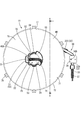
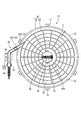
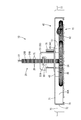
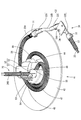
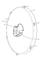
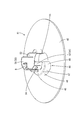
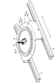
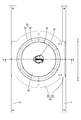
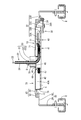
- FIG. Plan view of wire harness routing device Bottom view of wire harness routing device AA line sectional view of FIG. Perspective view of wire harness routing device with upper case removed Perspective view of upper case Top view of the upper case Lower case perspective view Lower case plan view
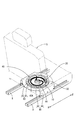
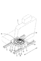
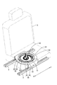
- the perspective view which shows the state which attached the wire harness wiring apparatus to the turntable
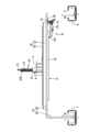
- the top view which shows the state which attached the wire harness wiring apparatus to the turntable Rear view showing a state in which the wire harness routing device is attached to the turntable Bottom view showing a state where the wire harness routing device is attached to the turntable BB sectional view of FIG.
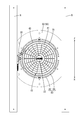
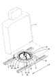
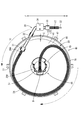
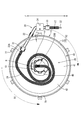
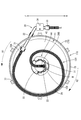
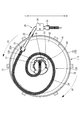
- a perspective view showing a state in which the case is facing forward with both seats Top view showing the case facing right The perspective view which shows the state which the case turned rightward from the front with respect to the seat
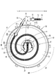
- the top view which shows the state where the case turned from the front to the right The perspective view which shows the state where the case turned to the left for both seats Top view showing the case facing left
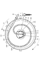
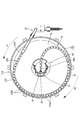
- the perspective view which shows the state where the case turned from the rear to the right for both seats The top view which shows the state where the case turned from right to left Sectional drawing equivalent to FIG. 15 of Embodiment 2.
- the principal part expanded sectional view of FIG. Plan view equivalent to FIG. 17 of the second embodiment The top view equivalent to FIG. 21 of Embodiment 2.
- FIG. 11 A first embodiment of the technology disclosed in this specification will be described with reference to FIGS. 1 to 25.
- the present embodiment illustrates a wire harness routing device 10 having a wire harness 20 routed between a base portion 90 and a seat S provided in a vehicle such as an automobile.
- the front-rear direction is described with reference to the arrow direction in each drawing, with the F side as the front side and the R side as the rear side.
- the seat S is a seat on the driver's seat side of the vehicle, for example, and as shown in FIGS. 16, 18, 20, 22, and 24, a pair of metal rails fixed to the floor of the vehicle
- the base portion 90 is slidable in the front-rear direction with respect to R.
- the base portion 90 includes a base body 92 having a substantially circular frame shape, and a pair of leg portions 94 that protrude slightly from the both ends of the base body 92 in the left-right direction and extend downward. have.
- the pair of leg portions 94 is assembled to be slidable in the front-rear direction with respect to the pair of rails R, and a turntable 80 (an example of a “rotation mechanism”) is fixed to the upper surface of the base body 92.
- the turntable 80 is made of metal and has a base side pedestal 82 fixed to the base body 92 and a seat side pedestal 84 that is rotatably supported by the base side pedestal 82.
- the base side pedestal 82 is formed in a flat annular shape, and is fixed to the base body 92 by bolt fastening or the like.
- the seat side pedestal 84 is formed in a flat annular shape that is slightly smaller than the base side pedestal 82, and is fixed to the bottom of the sheet S by bolt fastening or the like. Further, the seat side pedestal 84 is assembled inside the base side pedestal 82 via a bearing, and is rotatable with respect to the base side pedestal 82 about the axis of the base side pedestal 82. Accordingly, the sheet S can be rotated with respect to the base portion 90.
- the base side pedestal 82 and the seat side pedestal 84 are rotatable with respect to each other by a bearing.
- a known method for example, by providing an annular rail groove on the base side pedestal and providing a slider that can slide in the rail groove on the seat side pedestal, the base side pedestal and the seat side pedestal can be rotated relative to each other. May be.
- a stopper (not shown) is provided between the base side pedestal 82 and the seat side pedestal 84, and the base side pedestal 82 and the seat side pedestal 84 are prevented from rotating more than once by this stopper. Yes. Therefore, the seat S is turned rightward (see FIG. 18) rotated 90 degrees clockwise from the forward-facing state (see FIG. 16), and left-facing (see FIG. 18) rotated 90 degrees counterclockwise from the forward state. 20), a rearward state rotated 90 degrees from the leftward state (see FIG. 22), and a rightward state rotated 90 degrees further from the rearward state, and can be rotated in a range of 360 degrees.
- the wire harness routing device 10 includes a wire harness 20, a case 40 that houses the wire harness 20, and a base-side fixing member 30 that fixes one end of the wire harness 20 to the base portion 90. And is configured.
- One end of the wire harness 20 is a base-side end 20A arranged toward the base 90, and is connected to a device (not shown) such as an ECU (Electronic Control Unit) of the vehicle.
- a device such as an ECU (Electronic Control Unit) of the vehicle.
- the wire harness 20 routed toward the base portion 90 of the present embodiment is routed from the base portion 90 on the floor under the mat or the panel or below the floor, but is not illustrated.
- the other end portion of the wire harness 20 is a seat-side end portion 20B.
- an electric slide attached to the seat S an electric reclining motor, a seat heater, or any other electrical component (not shown) on the seat side. It is connected.
- the wire harness 20 performs power feeding and signal transmission / reception between the vehicle-side device and the electrical component of the seat S.
- the wire harness 20 includes a plurality (five in the present embodiment) of electric wires 22 and an exterior body 24 through which these electric wires 22 are inserted.
- Each electric wire 22 is formed by coating a core wire made of a metal having excellent conductivity with an insulating coating made of synthetic resin, and an end portion on the sheet side of each electric wire 22 is arranged in the sheet S and connected to each electrical component. Has been.
- the exterior body 24 is a corrugated tube formed of an insulating synthetic resin so as to be elastically deformable. As shown in FIG. 4, the exterior body 24 includes an annular small diameter portion 25 and a large diameter portion 26. It has a bellows shape (corrugated shape) formed alternately in the extending direction. A plurality of electrical wires 22 can be inserted into the exterior body 24, and the exterior body 24 can be bent in an arbitrary direction with the plurality of electrical wires 22 inserted.
- the base side end in a state in which the plurality of electric wires 22 are inserted by bringing the one end portions of the adjacent large diameter portions 26 close to each other in the exterior body 24.
- the portion 20A and the sheet side end portion 20B can be arbitrarily bent.
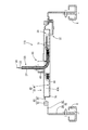
- the base-side fixing member 30 is made of synthetic resin, and is fixed to the base portion 90 in a state where the base-side end portion 20A of the wire harness 20 is held, as shown in FIGS.
- An exterior body holding portion 31 that holds the end of the exterior body 24 on the base portion 90 side, a guide cylinder portion 32 that guides the plurality of electric wires 22 drawn from the exterior body 24, and a guide cylinder portion 32.
- a corrugated holding portion 33 that holds a corrugated tube CT through which a plurality of drawn-out electric wires 22 are inserted, and a fixed piece 34 that fixes the guide tube portion 32 to the base portion 90 are configured.
- the exterior body holding part 31 has a substantially cylindrical shape that covers the end of the exterior body 24 of the wire harness 20 from the outside.
- a plurality of annular fitting portions (not shown) that can be fitted into the recesses 24 ⁇ / b> A provided between the small-diameter portion 25 and the large-diameter portion 26 of the exterior body 24 are provided on the inner peripheral surface of the exterior body holding portion 31.
- the base end portion 20 ⁇ / b> A of the wire harness 20 is held and fixed by fitting the annular fitting portion to the recess 24 ⁇ / b> A of the exterior body 24.
- the guide tube portion 32 is formed in a cylindrical shape having a smaller diameter than the exterior body holding portion 31 so as to be continuous with the exterior body holding portion 31.
- the plurality of electric wires 22 drawn out from the exterior body 24 can be inserted.
- the guide cylinder part 32 is directed downward from the first cylindrical part 32A extending straight from the end part of the exterior body holding part 31 in the same direction as the extension direction of the exterior body holding part 31, and from the front end part of the first cylindrical part 32A.
- the third cylindrical portion 32C extending straight from the lower end of the second cylindrical portion 32B in the same direction as the extending direction of the exterior body holding portion 31, and the third cylindrical portion 32C.
- the fourth cylindrical portion 32D is bent and extended from the distal end portion, and a fixed piece 34 is continuously provided on the upper portion of the fourth cylindrical portion 32D, and a corrugate is provided at the distal end of the fourth cylindrical portion 32D.
- a holding portion 33 is provided continuously.
- the fixed piece 34 rises upward from the upper portion of the fourth cylindrical portion 32D and then extends in the horizontal direction.
- the upper surface of the fixed piece 34 has a plate with respect to the base main body 92 of the base portion 90.
- a cylindrical portion 34A that can be fitted in the thickness direction is provided.
- the base side fixing member 30 is fixed to the base main body 92 by fitting the cylindrical portion 34A to the base main body 92 and fixing the fixing piece 34 and the base main body 92 by bolt fastening or the like. That is, the base side end portion 20 ⁇ / b> A of the wire harness 20 is fixed to the base portion 90 via the base side fixing member 30.
- the case 40 is made of synthetic resin and is formed in a circular shape in plan view as shown in FIGS.
- the outer diameter of the case 40 is set to be slightly smaller than the inner diameter of the seat side pedestal 84 of the turntable 80, and the case 40 can be arranged on the radially inner side of the seat side pedestal 84 of the turntable 80.
- the case 40 has a housing portion 40 ⁇ / b> A that houses the wire harness 20 therein, and the height of the housing portion 40 ⁇ / b> A is slightly smaller than the height of the turntable 80. It is set large. That is, the housing portion 40 ⁇ / b> A for housing the wire harness 20 in the case 40 is in a state of being almost housed at a position on the radially inner side of the turntable 80.
- a plurality (six in this embodiment) of mounting pieces 77 projecting outward are provided at equal intervals on the outer peripheral surface of the case 40.
- a concave screw recess 78 is provided at the projecting end of each mounting piece 77, and the case 40 is seated by inserting a screw into the screw recess 78 and tightening it to the seat side pedestal 84 of the turntable 80.
- the pedestal 84 is fixed.
- the case 40 when the case 40 is fixed to the turntable 80, the case 40 is arranged along the inner peripheral surface of the seat side pedestal 84, and the seat S faces right as shown in FIGS.
- the case 40 is rotated with the rotation of the seat S around the rotation axis of the turntable 80 in a range of 360 degrees from the rightward state to the counterclockwise direction after being rotated counterclockwise.
- the case 40 includes a lower case 41 and an upper case 70 assembled to the lower case 41 from above.
- the upper case 70 By assembling the upper case 70 to the lower case 41 from above, the lower case 41 41 and the upper case 70 constitute an accommodating portion 40A.
- the lower case 41 has a flat bottom plate portion 42 whose outer shape is a circular shape in plan view, and a sheet side fixing portion 44 provided on the bottom plate portion 42.
- the wire harness 20 drawn from the exterior body holding portion 31 of the base side fixing member 30 can be placed.
- the exterior body of the base side fixing member 30 that holds the base side end portion 20 ⁇ / b> A of the wire harness 20.
- the first cylindrical portion 32 ⁇ / b> A of the holding portion 31 and the guide cylinder portion 32 is arranged in a state of slightly floating upward from the bottom plate portion 42.
- the 2nd cylindrical part 32B in the guide cylinder part 32 of the base side fixing member 30 will be in the state extended below the bottom plate part 42 in the position outside the outer periphery of the bottom plate part 42, and the case 40 is sheet
- the second cylindrical portion 32B is relatively rotated around the outer periphery of the bottom plate portion 42 within a range of 360 degrees.
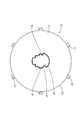
- the seat-side fixing portion 44 includes a protruding portion 46 that protrudes upward from the bottom plate portion 42, and a standing wall 50 that stands further upward from the upper surface of the protruding portion 46. have.
- the protruding portion 46 is formed in a rounded shape at the center of the bottom plate portion 42 when viewed from above, and a through hole 46A that penetrates the protruding portion 46 in the vertical direction is provided at the center of the protruding portion 46. .
- the projecting portion 46 has a projecting side wall 47 standing on the bottom plate portion 42 and a projecting upper wall 48 extending in a horizontal direction from the upper end portion of the projecting side wall 47 toward the center of the bottom plate portion 42. 46A is provided in the protruding upper wall 48 in a round hole shape.
- the protruding upper wall 48 is formed in a substantially annular shape at a part of the opening edge so as to follow the opening edge of the through hole 46A, and the right end portion of the protruding upper wall 48 protrudes outward in the radial direction. 49.
- the overhang end portion of the overhang portion 49 is formed in a substantially circular shape having a radius of curvature larger than the allowable radius of curvature in the exterior body 24 of the wire harness 20.
- the protruding side wall 47 has a shape in which the outer peripheral edge of the protruding upper wall 48 and the bottom plate portion 42 are connected in the vertical direction, and has a curved surface along the axis of the bottom plate portion 42 at the center of the bottom plate portion 42. Yes. Accordingly, a portion where the protruding upper wall 48 is not provided at the opening edge of the through hole 46A is in a state where the protruding side wall 47 is not formed.
- the standing wall 50 is formed in a substantially annular shape at a part of the opening edge so as to follow the opening edge of the through hole 46 ⁇ / b> A similarly to the protruding portion 46, and the portion where the standing wall 50 is formed is a through hole. 46A is the same as the protruding portion 46.
- the standing wall 50 includes a high standing wall 51 having a high vertical dimension and a low standing wall 52 having a height dimension lower than that of the high standing wall 51.
- the low standing wall 52 is a high standing wall. 51 on both sides.
- Each low standing wall 52 is provided with an elastic piece 53 that can be elastically deformed radially inward by being provided with a slit extending vertically, and each elastic piece 53 has a latch protruding outward.
- a protrusion 54 is provided.
- the portion facing the high standing wall 51 is in a state where the standing wall 50 is not formed, like the protruding side wall 47.
- the portion where the standing wall 50 is not formed and the portion where the protruding side wall 47 is not formed in the protruding portion 46 are positioned in the vertical direction in the seat-side fixing portion 44. 50 and the portion without the projecting side wall 47 is a harness insertion port 55 for communicating the inner part surrounded by the projecting side wall 47 and the standing wall 50 with the projecting side wall 47 and the outer part of the standing wall 50. .
- the wire harness 20 placed on the bottom plate portion 42 is drawn into the central portion of the bottom plate portion 42 surrounded by the protruding side wall 47 and the standing wall 50 through the harness insertion port 55.
- the wire harness 20 drawn through the harness insertion port 55 is bent upward along the upright wall 51 and guided upward on the seat S side.
- the high standing wall 51 is provided with a pair of band insertion holes 51A penetrating in the wall thickness direction.
- the binding band B is inserted into the pair of band insertion holes 51A and the outer body 24 of the wire harness 20 is attached together with the high standing wall 51.
- the sheet side end portion 20B of the wire harness 20 is fixed to the center portion of the bottom plate portion.
- the seat side end portion 20 ⁇ / b> B of the wire harness 20 is fixed in the vicinity of the rotation center of the case 40.
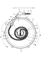
- the wire harness 20 fixed to the seat side fixing portion 44 is pulled out from the harness insertion port 55 onto the bottom plate portion 42 as shown in FIGS.
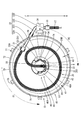
- the base-side end portion 20 ⁇ / b> A is held by the base-side fixing member 30 so as to be surrounded. 16 to 15, the top plate 71 of the upper case 70 described later is omitted in order to make the arrangement state of the wire harness 20 easy to understand.
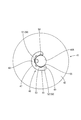
- the wire harness 20 is pulled diagonally right forward from the seat-side fixing portion 44, then folded back, and then the seat It arrange
- the wire harness 20 is pulled out from the seat side fixing portion 44 to the right and then folded back toward the left rear. Thereafter, the seat side fixing portion 44 is arranged so as to surround substantially one circumference along a circular side wall 72 of the upper case 70 described later.
- the wire harness 20 is wound around the seat-side fixing portion 44 and the case 40 is in a state of being turned from the front side to the left side as shown in FIG. After being pulled out from the left side, the sheet is bent forward, and thereafter, the seat-side fixing portion 44 is gently disposed so as to surround substantially one and a half rounds.
- the wire harness 20 is wound around the seat side fixing portion 44, and the case 40 is turned from the left side to the rear side as shown in FIG. After being pulled out rearward from the seat-side fixing portion 44, it is bent toward the left, and then disposed along the protruding side wall 47 of the protruding portion 46 of the seat-side fixing portion 44. Moreover, the wire harness 20 is arrange
- the wire harness 20 is moved from the seat side fixing portion 44 to the right side. After being pulled out, it is bent rearward, and then disposed so as to surround the seat side fixing portion 44 over about two rounds in a state where it contacts the protruding side wall 47 of the protruding portion 46 of the seat side fixing portion 44. .
- the upper case 70 includes a top plate 71 having a circular flat plate shape, a circular side wall 72 provided on the top plate 71, and a lock provided on the top surface of the top plate 71.
- the wall portion 75 is provided.
- the top plate 71 has an outer diameter that is slightly larger than the outer diameter of the bottom plate portion 42 of the lower case 41, and an insertion hole 74 that penetrates in the vertical direction, which is the thickness direction, is provided at the center of the top plate 71. It has been.
- the insertion hole 74 is configured such that when the upper case 70 is assembled to the lower case 41 from above, the standing wall 50 in the seat side fixing portion 44 of the lower case 41 is inserted from below.
- a lock wall 75 is provided at a part of the opening edge of the insertion hole 74.
- the lock wall portion 75 has an arc shape, and when the upper case 70 is assembled to the lower case 41, the lock wall portion 75 is arranged along the outer periphery of the standing wall 50. Further, in the opening edge of the insertion hole 74, the insertion hole 74 is widened in a fan shape at a portion where the lock wall portion 75 is not formed.
- a locked portion 76 is provided at a position corresponding to the elastic piece 53 of the standing wall 50 on the inner peripheral surface of the lock wall portion 75, and when the upper case 70 is assembled to the lower case 41, the engagement of the elastic piece 53 is provided. The upper case 70 is held in a state assembled to the lower case 41 by the locking projections 54 and the locked portions 76 being locked in the vertical direction.
- a circular side wall 72 is continuously formed on the outer peripheral edge of the top plate 71.
- the circular side wall 72 is configured to extend downward from the outer peripheral edge of the top plate 71, and a plurality of attachment pieces 77 are provided on the outer surface of the circular side wall 72 at equal intervals.
- the height dimension of the circular side wall 72 in the vertical direction is set to be slightly larger than the height dimension of the protruding portion 46 of the lower case 41 as shown in FIGS.
- the circular side wall 72 covers the wire harness 20 disposed on the bottom plate portion 42 of the lower case 41 together with the top plate 71, and the top plate 71, the circular side wall 72, and the bottom plate portion are covered.
- the housing part 40 ⁇ / b> A for housing the wire harness 20 is configured by 42.
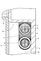
- a harness receiving portion 79 that slightly protrudes radially inward from the lower end portion of the circular side wall 72 is provided at the lower end portion of the circular side wall 72.
- the clearance dimension between the harness receiving part 79 and the outer peripheral edge of the bottom plate part 42 is set to be slightly larger than the outer diameter dimension of the second cylindrical part 32B in the guide cylindrical part 32 of the base side fixing member 30, and the base side
- the second cylindrical portion 32B is formed in the gap C between the harness receiving portion 79 and the outer peripheral edge of the bottom plate portion 42. It has come to be arranged.
- the harness receiving portion 79 is configured to support the wire harness 20 from below when the wire harness 20 is disposed on the inner peripheral surface of the circular side wall 72. That is, for example, when the wire harness 20 is arranged along the inner peripheral surface of the circular side wall 72 by the reaction force of the wire harness 20, the wire harness 20 is supported from below by the harness receiving portion 79.
- the 20 exterior bodies 24 can prevent the case 40 from being pulled out of the gap C to the outside.
- the present embodiment is configured as described above. Next, the operation and effect of the wire harness routing device 10 will be described.
- the wire harness routing device It becomes difficult to place.
- the rotation angle of the seat is increased to 360 degrees or the like, the extra length of the wire harness becomes longer, so that it becomes more difficult to arrange the wire harness routing device. End up.
- the case 40 can be arranged on the radially inner side of the seat-side base 84 of the turntable 80, and the housing portion 40 ⁇ / b> A for housing the wire harness 20 in the case 40 has a diameter of the turntable 80. It is in a state of being almost accommodated at a position inside the direction.
- the case 40 since the case 40 is disposed at a position radially inward of the seat side pedestal 84 that becomes a dead space in the seat side pedestal 84 in the turntable 80, the base portion 90 to which the seat S is fixed, the vehicle floor portion, and the like. Even when the space between them is limited, the wire harness routing device 10 that houses the wire harness 20 can be installed.
- the seat side pedestal 84 has an annular shape, and the case 40 is formed in a circular shape so as to follow the inner peripheral surface of the seat side pedestal 84.
- the extra length of the wire harness 20 can be accommodated in this space.
- the wire harness 20 that can be accommodated in the case 40 can be made longer than when a rectangular or small circular case is arranged. That is, it is effective when the rotation range of the sheet S is increased and the extra length of the wire harness 20 is increased as in the present embodiment.
- the base side end portion 20A of the wire harness 20 is held and fixed by the base side fixing member 30, and the seat side end portion 20B is fixed by the seat side fixing portion 44 of the lower case 41.
- the case 40 can be rotated while positioning the positions of both ends of the wire harness 20.
- the wire harness 20 is wound around the seat side fixing portion 44, and when the sheet S is rotated in the clockwise clockwise R2 direction.
- the wire harness 20 wound up at the seat-side fixing portion 44 is unwound and arranged around the seat-side fixing portion 44. That is, by rotating the case 40 in a range of 360 degrees according to the seat S, the extra length of the elongated wire harness 20 can be accommodated in the case 40 with a margin.
- the protruding portion 46 of the seat-side fixing portion 44 is provided with the overhanging portion 49 having a curvature radius larger than the allowable curvature radius of the exterior body 24 in the wire harness 20.
- the wire harness 20 when the wire harness 20 is wound around the seat-side fixing portion 44, the wire harness 20 is gently bent along the overhanging portion 49. Can be prevented from being bent excessively, and the wire harness 20 can be prevented from being damaged.
- the wire harness 120 in the wire harness routing device 110 according to the second embodiment is formed by inserting an elastic wire 128 together with a plurality of electric wires 22 into the exterior body 24 according to the first embodiment. Since the configurations, operations, and effects common to the first embodiment are duplicated, the description thereof is omitted. The same reference numerals are used for the same configurations as those in the first embodiment.
- the elastic wire 128 is a wire having rigidity that can be deformed in an arc shape, and is formed of, for example, a piano wire.
- the elastic wire 128 is configured to be slightly longer than the entire length of the exterior body 24, and is exposed from the sheet side end portion 20 ⁇ / b> B of the exterior body 24 when inserted into the exterior body 24.
- the exterior body 24 of the wire harness 120 of the present embodiment is gently curved by the reaction force that the elastic wire member 128 inserted therein tries to return to the original state.
- the wire harness 20 is pulled out diagonally right forward from the seat-side fixing portion 44, and then folded back toward the rear. It arrange
- the elastic wire 128 is inserted into the exterior body 24, and the wire harness 120 is gently curved in the housing portion 40 ⁇ / b> A of the case 40. Is arranged so as to wrap around the seat side fixing portion 44 substantially along the circular side wall 72 of the upper case 70.
- the case 40 is rotated together with the seat S toward the counterclockwise counterclockwise rotation R1, and the case 40 is turned from the forward-facing direction to the left-hand side as shown in FIG. If it will be in a state, the wire harness 20 will be wound up by the sheet
- the wire harness 20 is gently curved in the housing portion 40A of the case 40 by the elastic wire 128. It can be prevented that the harness 120 is tangled and the rotation of the case 40 is hindered.
- Embodiment 3 will be described with reference to FIGS.
- the wire harness 220 in the wire harness routing device 210 of the third embodiment is obtained by changing the shape of the exterior body 24 in the first embodiment, and the configuration, operation, and effects common to the first embodiment are duplicated. The description is omitted.
- the same reference numerals are used for the same configurations as those in the first embodiment.
- the exterior body 224 of the wire harness 220 of the third embodiment is formed of an insulating synthetic resin, and can be bent in only one direction with the plurality of electric wires 22 inserted.
- the exterior body 224 is connected to only one side portion of the substantially rectangular rectangular tube portion 224A, and can be bent only in the clockwise direction that is clockwise. It can be done. That is, the wire harness 20 can be formed in a spiral shape that is bent only in a clockwise direction from a linear state that extends linearly. Therefore, the exterior body 224 of the present embodiment regulates bending in a direction different from the winding direction.
- the wire harness 20 is pulled out obliquely forward to the right from the seat side fixing portion 44 and then toward the rear side. After that, the sheet side fixing portion 44 is gently wound around the circumference so as to be wound in a right-handed spiral shape.
- the case 40 is configured to rotate 360 degrees together with the sheet S.
- the present invention is not limited to this, and the rotation range of the case may be configured to be less than 360 degrees.
- the seat side pedestal 84 is rotatably supported inside the base side pedestal 82.
- the present invention is not limited to this, and the seat side pedestal may be rotatably supported outside the base side pedestal 82, and the case may be arranged radially inside the base side pedestal.
- the case 40 is formed in a circular shape so as to follow the inner peripheral surface of the seat side pedestal 84.
- the present invention is not limited to this, and the case may not be configured in a circular shape and may be configured in a small circular shape as long as the case is disposed on the radially inner side of the seat side pedestal.
- it was set as the structure by which the wire harness 20 is wound up right-handedly.
- the configuration is not limited to this, and the wire harness may be wound in a left-handed manner.
Landscapes
- Engineering & Computer Science (AREA)
- Mechanical Engineering (AREA)
- Aviation & Aerospace Engineering (AREA)
- Transportation (AREA)
- Electric Cable Arrangement Between Relatively Moving Parts (AREA)
- Seats For Vehicles (AREA)
Priority Applications (1)
| Application Number | Priority Date | Filing Date | Title |
|---|---|---|---|
| US17/054,732 US11325547B2 (en) | 2018-05-25 | 2019-05-14 | Wire harness routing apparatus |
Applications Claiming Priority (2)
| Application Number | Priority Date | Filing Date | Title |
|---|---|---|---|
| JP2018-100604 | 2018-05-25 | ||
| JP2018100604A JP7028061B2 (ja) | 2018-05-25 | 2018-05-25 | ワイヤハーネス配索装置 |
Publications (1)
| Publication Number | Publication Date |
|---|---|
| WO2019225391A1 true WO2019225391A1 (ja) | 2019-11-28 |
Family
ID=68616403
Family Applications (1)
| Application Number | Title | Priority Date | Filing Date |
|---|---|---|---|
| PCT/JP2019/019048 Ceased WO2019225391A1 (ja) | 2018-05-25 | 2019-05-14 | ワイヤハーネス配索装置 |
Country Status (3)
| Country | Link |
|---|---|
| US (1) | US11325547B2 (enExample) |
| JP (1) | JP7028061B2 (enExample) |
| WO (1) | WO2019225391A1 (enExample) |
Families Citing this family (3)
| Publication number | Priority date | Publication date | Assignee | Title |
|---|---|---|---|---|
| JP7365550B2 (ja) * | 2019-07-04 | 2023-10-20 | テイ・エス テック株式会社 | 車両用シート装置 |
| JP7572600B2 (ja) * | 2019-12-03 | 2024-10-24 | テイ・エス テック株式会社 | 車両用回転シート装置 |
| FR3146104B1 (fr) * | 2023-02-27 | 2025-02-28 | Faurecia Sieges Dautomobile | Ensemble pour siege de vehicule |
Citations (3)
| Publication number | Priority date | Publication date | Assignee | Title |
|---|---|---|---|---|
| JPH01101123U (enExample) * | 1987-12-25 | 1989-07-07 | ||
| WO2013155032A1 (en) * | 2012-04-13 | 2013-10-17 | Rethink Robotics, Inc. | Management of cables that traverse moving robot joints |
| JP6052148B2 (ja) * | 2013-12-06 | 2016-12-27 | 住友電装株式会社 | シート用ワイヤハーネスの配索装置 |
Family Cites Families (4)
| Publication number | Priority date | Publication date | Assignee | Title |
|---|---|---|---|---|
| US4542858A (en) * | 1984-05-23 | 1985-09-24 | The United States Of America As Represented By The Administrator Of The National Aeronautics And Space Administration | Rotatable electric cable connecting system |
| KR100588696B1 (ko) * | 2004-10-19 | 2006-06-12 | 기아자동차주식회사 | 시트 와이어 하넥스 길이 조절 장치 |
| JP5136480B2 (ja) | 2009-03-17 | 2013-02-06 | 株式会社デンソーウェーブ | ロボットの回転関節用配線装置 |
| JP6772554B2 (ja) | 2016-05-26 | 2020-10-21 | トヨタ紡織株式会社 | 回転装置 |
-
2018
- 2018-05-25 JP JP2018100604A patent/JP7028061B2/ja active Active
-
2019
- 2019-05-14 WO PCT/JP2019/019048 patent/WO2019225391A1/ja not_active Ceased
- 2019-05-14 US US17/054,732 patent/US11325547B2/en active Active
Patent Citations (3)
| Publication number | Priority date | Publication date | Assignee | Title |
|---|---|---|---|---|
| JPH01101123U (enExample) * | 1987-12-25 | 1989-07-07 | ||
| WO2013155032A1 (en) * | 2012-04-13 | 2013-10-17 | Rethink Robotics, Inc. | Management of cables that traverse moving robot joints |
| JP6052148B2 (ja) * | 2013-12-06 | 2016-12-27 | 住友電装株式会社 | シート用ワイヤハーネスの配索装置 |
Also Published As
| Publication number | Publication date |
|---|---|
| JP7028061B2 (ja) | 2022-03-02 |
| US20210245683A1 (en) | 2021-08-12 |
| US11325547B2 (en) | 2022-05-10 |
| JP2019202724A (ja) | 2019-11-28 |
Similar Documents
| Publication | Publication Date | Title |
|---|---|---|
| WO2019225391A1 (ja) | ワイヤハーネス配索装置 | |
| US11420573B2 (en) | Wire harness routing apparatus | |
| KR102150593B1 (ko) | 자동차용 시트레일 구조 | |
| JP2019053894A (ja) | ワイヤハーネス | |
| JP5245429B2 (ja) | ケーブル配索構造 | |
| WO2010103904A1 (ja) | 給電装置 | |
| JP6112660B2 (ja) | フラットケーブル配索構造 | |
| JP4381997B2 (ja) | バックル装置 | |
| US20200223379A1 (en) | Wire harness for seat | |
| JP2020114082A (ja) | シート用ワイヤハーネス | |
| JP6052148B2 (ja) | シート用ワイヤハーネスの配索装置 | |
| US11975663B2 (en) | Wire harness routing apparatus | |
| JP2022188844A (ja) | プロテクタ、及び、ワイヤハーネス | |
| JP2006304538A (ja) | ハーネス配索構造 | |
| JP7180531B2 (ja) | ワイヤーハーネス配索装置 | |
| JP6841724B2 (ja) | 電線ガイド装置 | |
| JP2016037057A (ja) | ヘッドレストおよびシート | |
| WO2024204306A1 (ja) | ケーブル巻取装置及びシート給電装置 | |
| KR20250167581A (ko) | 케이블 권취 장치 및 시트 급전 장치 | |
| JP6285712B2 (ja) | フラットケーブル巻取装置 | |
| JP2014076779A (ja) | リクライニングシートの配線構造 | |
| JP2024142814A (ja) | ケーブル巻取装置及びシート給電装置 | |
| JP7151590B2 (ja) | ワイヤハーネス | |
| JP2025041379A (ja) | 着座用シート | |
| WO2025182995A1 (ja) | 電気ケーブル巻取装置、並びに、電気ケーブル巻取装置を用いたハンドル給電装置及びシート給電装置 |
Legal Events
| Date | Code | Title | Description |
|---|---|---|---|
| 121 | Ep: the epo has been informed by wipo that ep was designated in this application |
Ref document number: 19807985 Country of ref document: EP Kind code of ref document: A1 |
|
| NENP | Non-entry into the national phase |
Ref country code: DE |
|
| 122 | Ep: pct application non-entry in european phase |
Ref document number: 19807985 Country of ref document: EP Kind code of ref document: A1 |