WO2019220748A1 - 粉粒体散布量検査装置及び検査方法、並びに粉粒体含有物品の製造装置及び製造方法 - Google Patents
粉粒体散布量検査装置及び検査方法、並びに粉粒体含有物品の製造装置及び製造方法 Download PDFInfo
- Publication number
- WO2019220748A1 WO2019220748A1 PCT/JP2019/008795 JP2019008795W WO2019220748A1 WO 2019220748 A1 WO2019220748 A1 WO 2019220748A1 JP 2019008795 W JP2019008795 W JP 2019008795W WO 2019220748 A1 WO2019220748 A1 WO 2019220748A1
- Authority
- WO
- WIPO (PCT)
- Prior art keywords
- granular material
- amount
- calibration curve
- mass
- powder
- Prior art date
- Legal status (The legal status is an assumption and is not a legal conclusion. Google has not performed a legal analysis and makes no representation as to the accuracy of the status listed.)
- Ceased
Links
Images


Classifications
-
- G—PHYSICS
- G01—MEASURING; TESTING
- G01G—WEIGHING
- G01G13/00—Weighing apparatus with automatic feed or discharge for weighing-out batches of material
- G01G13/16—Means for automatically discharging weigh receptacles under control of the weighing mechanism
-
- G—PHYSICS
- G01—MEASURING; TESTING
- G01N—INVESTIGATING OR ANALYSING MATERIALS BY DETERMINING THEIR CHEMICAL OR PHYSICAL PROPERTIES
- G01N15/00—Investigating characteristics of particles; Investigating permeability, pore-volume or surface-area of porous materials
- G01N15/02—Investigating particle size or size distribution
Definitions
- the present invention relates to an apparatus and a method for inspecting the amount of dust particles used in a step of spraying particles stored in a container onto an object to be dispersed. Moreover, this invention relates to the manufacturing apparatus and manufacturing method of a granular material containing article.
- a method for transporting and supplying powder particles stored in a container such as a hopper to the outside of the container a method of vibrating the transport path of the powder particles is known.
- the flow rate (conveyance amount per unit time) of the granular material can be adjusted by adjusting the vibration intensity of the conveyance path.
- the mass of the granular material stored in the container is continuously measured, and the change in mass per unit time (mass decrease amount) is calculated as the flow rate of the powder.
- a so-called loss-in-wait method for measuring flow rate is known.
- Patent Document 3 describes a method of measuring the mass and the like of a high-temperature granular material aggregate such as reduced iron pellets on a conveyor using an infrared or near-infrared CCD camera.
- the camera captures the difference in image density due to the temperature difference, obtains the area of the aggregate, and converts it to mass using a calibration curve.
- assembly is grasped
- Patent Document 4 describes a mass inspection apparatus for a granular material that can continuously detect the mass of the granular material constituting a product during spraying.
- this apparatus the pixel of the granular material obtained from the binarized image data at the initial stage of inspection and the mass of the granular material measured at a predetermined time by the mass measuring unit below the dropping trajectory of the granular material.
- a standard calibration curve indicating the correspondence relationship between the pixel and the mass by a linear function is created, and further, the standard calibration curve and the particle size of the granular material at the initial stage of inspection calculated from the binarized image data
- the particle size of the granular material to be inspected is calculated, and using the calculated value of the particle size, the inclination of the reference calibration curve is corrected to create a corrected calibration curve.
- the mass value of the granular material ie, the amount of dispersion
- the present invention discharges the granular material stored in the container from the container, and during the execution of the granular material spraying step of freely dropping the discharged granular material and spraying it on the object to be sprayed, It is a granular material spraying amount inspection apparatus that inspects the mass of a granular material sprayed on a spray object.
- the granular material spray amount inspection device of the present invention continuously measures the total mass of the mass of the container and the mass of the granular material in the container with a measuring means in time, and the total mass at a predetermined time t1.
- a second measuring mechanism is provided for measuring the amount of the powder particles sprayed at a certain time t2.
- the present invention discharges the granular material stored in the container from the container, and during the implementation of the granular material spraying step of freely dropping the discharged granular material and spraying it on the object to be sprayed, It is a granular material spraying amount inspection method for inspecting the mass of the granular material sprayed on the spray object.
- the method for inspecting the amount of the granular material in the present invention the total mass of the mass of the container and the mass of the granular material in the container is continuously measured with a measuring means in time, and the total mass at a predetermined time t1.
- a mass change amount measuring step for measuring the amount of change.
- diffusion amount inspection method of this invention has an imaging process process which acquires the image data by imaging the granular material which falls freely toward the said dispersion
- diffusion amount inspection method of this invention has a binarization process process which binarizes the said image data based on a predetermined threshold value, and produces
- the granular material spray amount inspection method of the present invention includes the cumulative pixel of the granular material obtained from the binarized image data accumulated at the predetermined time t1, and the mass change amount measurement step.
- the granular material spraying amount inspection method of the present invention includes a spraying amount measuring step of measuring the spraying amount of the granular material at a certain time t2 during the execution of the powdery particle spraying step based on the calibration curve. .
- the granular material stored in the container is discharged from the container, and the discharged granular material is transported in a predetermined direction by the transporting means and then freely dropped from the transporting means.
- It is a manufacturing apparatus of the granular material containing article which manufactures the article containing this granular material by implementation of the granular material spreading process spread to a spreading object.
- the apparatus for producing a granular material-containing article of the present invention measures the total mass of the mass of the container and the mass of the granular material in the container continuously in time with a measuring means, and the total at a predetermined time t1.
- a first measurement mechanism for measuring a change in mass is provided.
- the apparatus for producing a granular material-containing article of the present invention obtains image data by capturing an image of the granular material that freely falls from the conveying means toward the object to be sprayed, and obtains the image data.
- Binarization processing is performed based on a threshold value to generate and accumulate binarized image data, and the accumulated pixels of the granular material obtained from the binarized image data accumulated at the predetermined time t1, the first Based on the change amount at the predetermined time t1 measured by the measurement mechanism, a calibration curve indicating a correspondence relationship between the accumulated pixel and the change amount is created, and the powder and granular material is dispersed based on the calibration curve.
- a second measuring mechanism is provided for measuring the amount of the powder particles sprayed at a certain time t2 during the process.
- the granular material stored in the container is discharged from the container, and the discharged granular material is transported in a predetermined direction by the transporting means and then freely dropped from the transporting means.
- It is a manufacturing method of a granular material content article which manufactures an article containing this granular material by implementation of a granular material spreading process spread to a spreading object.
- the total mass of the mass of the container and the mass of the granular material in the container is continuously measured in time by a measuring means, and the total at a predetermined time t1 is measured.
- the manufacturing method of the granular material containing article of this invention has an imaging process process which captures the granular material which falls freely from the said conveyance means toward the said dispersion
- the manufacturing method of the granular material containing article of this invention has the binarization process process which produces
- the manufacturing method of the granular material containing article of this invention was measured by the cumulative pixel of the granular material obtained from the said binarized image data accumulate
- FIG. 1 is a schematic configuration diagram of an embodiment of an apparatus for producing a granule-containing article used for carrying out the method for producing a granule-containing article of the present invention.
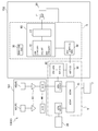
- FIG. 2 is a block diagram showing a control system of the manufacturing apparatus shown in FIG. 1, and is also a schematic configuration diagram of one embodiment of the granular material spray amount inspection apparatus of the present invention.
- FIG. 3 is a diagram illustrating an example of a measurement result of a control mass change amount measuring step in the method for inspecting the amount of dispersed granular material according to the present invention.
- FIG. 4 is a diagram showing an example of an algorithm for a calibration curve creation method in the method for inspecting the amount of scattered powder of the present invention.
- FIG. 5 is an example of an image obtained by imaging particles of a granular material to be inspected.
- FIG. 6 is an image obtained by binarizing the image shown in FIG.
- FIG. 7 is a graph showing an example of a calibration curve according to the present invention.
- FIG. 8A is a graph showing the change over time of the particle size variation rate of the granular material, which is calculated from the captured image data of the granular material discharged from the container and freely falling toward the object to be spread
- FIG. (B) is a graph showing the change over time of the actual measurement value of the change amount of the powdered granular material in the container at that time
- FIG. 8 (c) is a measurement of the spraying amount of the granular material calculated from the captured image data.
- FIG. 9 is a diagram showing an example of an abnormality determination step of the measuring means in the method for inspecting the amount of scattered powder of the present invention.
- FIG. 10 (a) is a graph of the change over time in the amount of spray obtained by measuring the amount of spray with a load cell type meter
- FIG. 10 (b) is the powder calculated based on the image data of the free-falling powder.
- FIG. 10C is a graph showing the change over time in the particle diameter of the body
- FIG. 10C is a graph showing the change over time obtained by measuring the amount of application using image data in Reference Example 1
- FIG. 10D is the slope of the calibration curve (calibration).
- FIG. 10E is a graph of the change over time obtained by the scattering amount measurement based on the image data in the first embodiment.
- the present invention relates to a technique capable of accurately grasping the amount of sprayed powder during spraying.
- FIG. 1 shows a schematic configuration of a production apparatus 1 which is an embodiment of the production apparatus for a granular material-containing article of the present invention.
- the manufacturing apparatus 1 discharges the granular material P stored in a hopper 2 as a container from the hopper 2, and the discharged granular material P is conveyed by a conveying means 3 to a predetermined level.
- the article containing the granular material P is manufactured by freely dropping from the conveying means 3 and then spraying on the object T to be dispersed. It can also be said to be an “apparatus”.
- Examples of the granular material-containing article manufactured by the manufacturing apparatus 1 include a heating element containing water-absorbing polymer particles as the granular material P.
- diffusion target object T a base material sheet
- the granular material P in addition to the water-absorbing polymer particles, for example, sugar, activated carbon, wheat flour, polyethylene pellets, polypropylene pellets, polyethylene terephthalate chips, polycarbonate chips, polyethylene granules, polyacrylic butyl beads and other organic particles And powders of inorganic substances such as body, metal powder, sodium chloride, potassium chloride, calcium chloride, magnesium chloride, glass and lime.
- the shape of the granular material P is not particularly limited, and examples thereof include a spherical shape, a meteorite shape, an elliptical shape, an elliptical column, a needle shape, and a cubic shape. According to the present invention, it is possible to disperse with good quantitativeness even if the granular material P has a true spherical shape, and even in a shape other than a true spherical shape.
- the manufacturing apparatus 1 includes a hopper (container) 2 that can temporarily store the powder P in the inside thereof, and the powder P discharged from the hopper 2 in one direction in a predetermined horizontal direction indicated by a symbol X in the figure.
- Conveying means 3 for conveying and spreading on a substrate sheet T (dispersion target) that is continuously conveyed is provided.
- the base sheet T can be continuously conveyed by a known conveyance device such as a conveyance roll as shown in FIG. 1 or a belt conveyor. Note that the base sheet T and its conveying device do not constitute the manufacturing apparatus 1.
- the hopper 2 has a trapezoidal shape in which the upper base is longer than the lower base when viewed from the side as shown in FIG. 1, that is, when viewed from a direction orthogonal to the conveying direction X of the powder P by the conveying means 3.
- a portion 21 and a discharge portion 22 having a rectangular parallelepiped shape connected to the lower end of the storage portion 21 and having a rectangular shape in a side view are configured.
- the storage unit 21 has a space in which the granular material P can be stored, and the granular material P can be temporarily stored in the internal space.
- the granular material P is supplied from the upper opening of the storage unit 21 to the internal space of the storage unit 21 by the granular material supply means 24.
- the discharge part 22 has a moving path for the powder P inside, and a discharge port 23 for the powder P is formed at the lower end of the discharge part 22 (the end opposite to the storage part 21 side).
- the internal space of the storage unit 21 and the discharge port 23 communicate with each other through the moving path.
- the conveying means 3 includes a receiving means (trough) 35 that receives the powder P discharged from the outlet 23 of the hopper 2 and conveys it in the horizontal direction, and is arranged on one end side of the receiving means 35. And a vibration generating means 36 for vibrating the receiving means 35 in a cantilever state.
- the conveying means 3 is arranged with a gap with respect to the discharge port 23 located at the lower end of the hopper 2.
- the vibration generating means 36 is fixed to the lower surface of the receiving means 35 (the surface opposite to the receiving surface of the powder particles P).
- the receiving means 35 is used for receiving and transporting the granular material P (in contact with the granular material P) is a portion located below the hopper 2 (discharge port 23) and its vicinity, and the others. This portion is basically a non-contact part of the granular material that does not come into contact with the granular material P.
- the vibration generating means 36 is fixed to the lower surface of the non-contact part of the granular material of the receiving means 35.
- the conveying means 3 operates the vibration generating means 36 to vibrate the receiving means 35 so that the granular material P on the receiving means 35 can be conveyed in a predetermined direction.
- the manufacturing apparatus 1 includes a control unit 5 that controls the voltage and frequency applied to the vibration generating unit 36, and the control unit 5 controls the frequency and / or amplitude of the receiving unit 35.
- the conveyance state of the granular material P on the receiving means 35 is controlled, and the spraying amount of the granular material P with respect to the base material sheet T which is a dispersion
- the vibration generating means 36 when the vibration generating means 36 is inactive, the receiving means 35 is not vibrating, so that the conveyance of the granular material P on the receiving means 35 is stopped or suppressed.
- the vibration generating means 36 When the vibration generating means 36 is operated from the state, the receiving means 35 starts to vibrate, so that the stopping or suppression of the powder P on the receiving means 35 is released.
- the base material sheet (spreading object) is finally transported below the receiving means 35 by dropping from the front end portion in the conveying direction X of the receiving means 35. ) Continuously sprayed on T.
- the receiving means 35 is preferably a flat plate from the viewpoint of appropriately transmitting the vibration generated by the vibration generating means 36 to the powder P on the receiving means 35. More specifically, FIG. A flat plate member as shown is preferred. Although the material of the receiving means 35 which consists of such a flat plate member is not restrict
- the vibration generating unit 36 may be any unit capable of generating a vibration component capable of transporting the granular material P on the receiving unit 35 in a desired direction.
- a piezoelectric element such as a piezoelectric ceramic, a vibration feeder, or the like can be used.
- a well-known vibration generating means is mentioned.
- Two measuring means 4A and 4B are attached to the hopper 2 as the measuring means 4. More specifically, as shown in FIG. 1, the weighing means 4 ⁇ / b> A is fixed to a wall portion defining the storage portion 21 of the hopper 2 via a support member 41, and another support member 42 is attached to the support member 41. The measuring means 4B is fixed via the. The support member 42 that supports the weighing means 4B is not in contact with the hopper 2 and, therefore, the mounting positions of both the weighing means 4A and 4B in the hopper 2 are the same. Note that the mounting positions and fixing methods of the weighing means 4A and 4B are not limited to the illustrated form, and can be appropriately adjusted within a range where the weighing can be accurately performed. For example, the weighing means 4A and 4B include the support members 41 and 42, respectively. You may attach directly to the wall part of the hopper 2 without going through.
- the total mass of the mass of the hopper 2 and the mass of the powder particles P in the hopper 2, that is, the mass of the hopper-containing powder particles can be continuously measured.
- measurable continuously in time means that the sampling time of the measurement data is 1 second or less.
- the total mass measurement data measured by the measurement unit 4 is transmitted to the control unit 5 every time data is acquired.
- a specific example of the measuring means 4 is an electric measuring instrument. Specifically, a load cell measuring instrument, an electromagnetic measuring instrument, a tuning fork measuring instrument, or the like can be used. Both weighing means 4A and 4B may be the same or different from each other.
- the control unit 5 controls the entire operation of the manufacturing apparatus 1 and includes a CPU, a ROM, a RAM, and the like. As shown in FIG. 1, a display unit 7 such as an image monitor is connected to the control unit 5, and data and operation signals are supplied to the control unit 5 from an input unit (not shown). The measured value of the spray amount of the granular material P is displayed.
- FIG. 2 shows a schematic configuration of the control system of the manufacturing apparatus 1.
- the control system of the manufacturing apparatus 1 shown in FIG. 2 includes the control system of the granular material spray amount inspection apparatus 100 included in the manufacturing apparatus 1.
- the granular material spraying amount inspection apparatus 100 discharges the granular material P stored in the hopper 2 from the hopper 2, and freely drops the discharged granular material P to form a base material sheet that is an object to be dispersed. It is an apparatus for inspecting the mass, that is, the spraying amount of the granular material P sprayed on the base sheet T during the execution of the granular material spraying step sprayed on T.
- the manufacturing apparatus 1 is configured to include a powder particle spray amount inspection device 100 in addition to the powder particle spray unit including the hopper 2 and the transport unit 3 as the containers described above.
- a hopper is formed by a so-called loss-in-weight type.
- coating amount with respect to the base material sheet T of the granular material P from the image data of the granular material P to perform is mentioned.
- two functions of said 1) and 2) are exhibited by the granular material spray amount inspection apparatus 100 which the manufacturing apparatus 1 comprises.
- the powder particle amount inspection apparatus 100 includes a control unit 5, a first measurement mechanism 101 mainly related to the function 1), and a second mainly related to the function 2).
- the measuring mechanism 102 is configured.
- the granular material spray amount inspection device 100 may be composed of an assembly of a plurality of devices divided for each component such as the control unit 5 and the two measurement mechanisms 101 and 102, and one device. It may consist of.
- the first measuring mechanism 101 includes a measuring unit 4 that measures the mass of the powder P in the hopper 2 together with the hopper 2.
- the first measurement mechanism 101 includes two weighing means 4A and 4B as the weighing means 4.
- the measurement result (change amount ⁇ Ga of the container-containing granular mass G) of one of these two units is used for operation control of the vibration generating unit 36 by the control unit 5, and the other measurement unit 4B.
- the measurement result (change amount ⁇ Gb of the container-containing granule mass G) is used by the second measurement mechanism 102 to create the calibration curve 40F.
- an operational amplifier circuit 43 and an A / D converter 44 are connected to both weighing means 4A and 4B, respectively, and the analog weighing signal from both weighing means 4A and 4B is amplified by the operational amplifier circuit 43. Thereafter, it is digitized by the A / D converter 44 and supplied to the control unit 5.
- the second measuring mechanism 102 is free-falling toward a part of the control unit 5 (a calibration curve creation unit 40 and a calibration curve storage area unit 50) and the base material sheet T that is a scattering object.
- the imaging unit 11 and the illumination unit 20 that are used for generating image data of the granular material P to be processed, and the image processing control unit 6 that performs image processing and the like of the image data are configured.
- the image processing control unit 6 is typically configured as a device constructed based on a computer or image controller in which image processing software or the like is installed.
- the granular material spraying amount inspection device 100 continuously measures the powder-in-mass mass G in the container by the first measuring mechanism 101 in a loss-in-weight manner, The amount of change ⁇ Ga, ⁇ Gb of the mass G at the “predetermined time” (predetermined sampling time) is measured (mass change amount measuring step). Then, in the manufacturing apparatus 1, as shown in FIG. 2, the amount of change ⁇ Ga obtained by the weighing means 4 ⁇ / b> A is used to control the spraying amount of the granular material P and to the hopper 2 under the control of the control unit 5. The control of the supply timing of the granular material P is performed. Further, the change amount ⁇ Gb obtained by the measuring means 4B is used by the second measurement mechanism 102 to create a calibration curve 40F.
- control mass change The amount of change in the powder mass G in the container used for controlling the amount of the powder P, etc.
- mass change amount for calibration curve The amount of change in the powder mass G (hereinafter also referred to as “mass change amount for calibration curve”) is different from the “predetermined time”, that is, the sampling time when measuring these.
- control cycle time the sampling time when measuring the control mass change amount
- control cycle time the sampling time when measuring the control mass change amount
- the sampling time for measuring the mass change amount for the calibration curve is also referred to as “calibration curve measurement time”, and may be denoted as “predetermined time t1” or “calibration curve measurement time t1” with reference t1. is there.
- the control mass change amount is the change amount ⁇ Ga obtained by the weighing means 4A
- the calibration curve mass change amount is the change amount ⁇ Gb obtained by the measurement means 4B. .
- the control cycle time t4 for measuring the control mass change amount is a short time from the viewpoint of promptly responding to a phenomenon in which the variable of the actual measurement value undulates (so-called hunting) due to the control operation. It is preferable that it is usually several seconds.
- the calibration curve measurement time t1 for measuring the calibration curve mass change amount is usually controlled. It is longer than the cycle time t4 and is about several seconds to several tens of seconds. However, the calibration curve measurement time t1 and the control cycle time t4 may be the same.
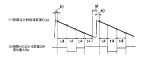
- FIG. 3 shows an example of a measurement result of the control mass change amount (change amount ⁇ Ga in the present embodiment).
- the manufacturing apparatus 1 discharges the granular material P stored in the hopper 2 from the discharge port 23 as shown in FIG. 3 is a loss-in-weight type, and the powdered granular material mass G is continuously measured over time, so that the measured value of the mass G can be obtained as shown in (1) of FIG. Decreases with progress.
- a lower limit value is set in advance for the powder mass G in the container, and when the measured value of the mass G reaches the lower limit value, the powder particles arranged above the hopper 2 under the control of the control unit 5.
- the powder P is replenished from the body supply means 24 (see FIG. 1).
- This replenishment of the granular material P is performed up to a predetermined upper limit value of the container-containing granular material mass G.
- the time indicated by the symbol St in (1) in FIG. 3 is the replenishment time of the granular material P, and it is preferable not to measure the mass G in the container during the replenishment time St.
- the powder particle mass G in the container matches the upper limit (the powder P is supplied from the powder supply means 24 into the hopper 2 to the predetermined upper limit).
- the discharge initial time t0 which is a fixed time after the start of discharging the body P, is unstable in discharging the powder P from the hopper 2, and therefore the amount of spraying the powder P tends not to be stable, If such a measured value of the unstable discharge initial time t0 is used for the inspection, the accuracy of the inspection result may be lowered. Therefore, the mass G is measured not only during the replenishment time St but also during the initial discharge time t0. It is preferable not to do so.
- the container-containing powder mass G is measured by the measuring means 4.
- the initial discharge time t0 is preferably 2 seconds or more, more preferably 3 seconds or more, and preferably 10 seconds or less, more preferably 5 seconds or less. From the same point of view, it is preferable to measure the mass G in the container by the measuring means 4 when the storage amount of the powder P in the hopper 2 is approximately half of the maximum storage amount of the hopper 2. . If the stored amount of the granular material P in the hopper 2 is too small, the discharge of the granular material P from the discharge port 23 becomes unstable, and the accuracy of the measured value of the container-containing granular material mass G may be lowered. .
- the powder particle amount inspection apparatus 100 continuously measures the powder content G in a container temporally by the measuring means 4A in the first measurement mechanism 101, A change amount ⁇ Ga (control mass change amount) of the mass G at a predetermined time (control cycle time) t4 is measured (control mass change amount measurement step).
- This change ⁇ Ga is defined by subtracting the mass G2 from the mass G1 (mass G1-mass G2).
- Mass G1 is the mass in the container at a certain time (starting time of one sampling time), and “Mass G2” is after time t4 has elapsed from the time (the end of the one sampling time) Time)).
- the mass G in the container typically has a sampling time (control cycle time t4) of a plurality of samples every several seconds to several tens of seconds. It is weighed by performing it continuously.
- FIG. 3 (2) shows the change ⁇ Ga in each sampling when sampling is performed a plurality of times at the predetermined time t4, that is, the change ⁇ Ga in the control cycle time t4.
- the analog weighing signals of the masses G 1 and G 2 from the weighing means 4 A are amplified by the operational amplification circuit 43 and digitally converted by the A / D converter 44.
- the change amount ⁇ Ga of the container-containing granular mass G at the control cycle time t 4 is measured from the digitized masses G 1 and G 2 in the control unit 5.
- the amount of change ⁇ Ga in the control cycle time t4 thus measured is the amount of decrease in the mass of the powder P in the hopper 2 at the control cycle time t4, that is, the hopper 2 It is equal to the discharge amount of the granular material P from.
- the discharge amount of the granular material P from the hopper 2 in the control cycle time t4 is equal to the spraying amount of the granular material P on the spray target T in the control cycle time t4.
- Control cycle time t4 in the measurement of the container-containing granular mass G when measuring the change ⁇ Ga (the control mass change), that is, “one time when measuring the mass G by sampling a plurality of times.
- the “sampling time per hit” can be arbitrarily set as appropriate.
- the control cycle time t4 may be set according to the content of the granular material P per product in the base material sheet T which is the object to be sprayed, but if the measured mass is too small, a longer time is set. do it.
- the granular material is supplied from the granular material supply means 24 from the state where the granular material P is replenished in the hopper 2 to a predetermined upper limit value. It can be set as appropriate within the time until P is supplied.
- the transfer capability of the transfer unit 3 can be changed by controlling the voltage and / or frequency applied to the vibration generating unit 36.
- a known feedback control method such as P control (proportional control), PI control or PID control can be employed.
- the coefficients in these various control methods can be determined by trial and error.
- the control of the amount of powder P the method described in Japanese Patent Application Laid-Open No. 2017-94294 related to the previous application of the present applicant can be used as appropriate.
- the granular material spray amount inspection apparatus 100 continuously measures the granular mass G in the container with time by the measuring means 4B in the first measuring mechanism 101. Then, a change amount ⁇ Gb (mass change amount for the calibration curve) of the mass G at a predetermined time (calibration curve measurement time) t1 is measured (mass change amount measurement step for the calibration curve).
- This mass change amount measuring step for measuring the change amount ⁇ Gb uses a measuring means 4B different from the measuring means 4A used for measuring the change amount ⁇ Ga, and, as described above, the sampling time (the “predetermined time”).
- the basic function of the second measuring mechanism 102 is that image data is obtained by capturing an image of the granular material P that freely falls from the conveying means 3 toward the base material sheet T that is a dispersion target. 10 W is obtained, and the image data 10 W is binarized based on a predetermined threshold value to generate and store the binarized image data 30 W, and the binarization stored at a predetermined time (calibration curve measurement time) t 1
- the calibration curve 40F indicating the correspondence between the accumulated pixel V and the change amount ⁇ G is created based on the “and the powder distribution at a certain time t2 during the execution of the granular material spraying process based on the calibration curve 40F. Calculating the amount of particle P spread It is intended.
- this “certain time t2” is also referred to as “spreading amount measurement time t2.”
- the second measuring mechanism 102 mainly performs the function of creating the calibration curve 40F from the image data 10W of the free-falling granular material P, and the granular material spraying step based on the generated calibration curve 40F.
- the former function is related to the calibration curve measurement time t1
- the latter function is related to the dispersion amount measurement time t2
- Both times t1 and t2 are generated at different timings.
- the calibration curve creation is 11W and the mass calculation is 12W, and the image data is differentiated.
- the second measurement mechanism 102 includes an imaging processing unit 10, an illumination unit 20, a binarization processing unit 30, a calibration curve creation unit 40, a calibration curve storage area unit 50, and a mass calculation unit 60.
- the basic functions are exhibited when these components 10 to 60 operate.
- the image processing control unit 6 is a portion excluding the calibration curve creation unit 40 and the calibration curve storage area unit 50, the illumination unit 20 and the imaging means 11 included in the control unit 5. is there.
- the imaging unit 11 and the illuminating unit 20 form a drop trajectory space of the granular material P that freely falls from the front end portion in the transport direction X of the receiving unit 35 in the transport unit 3. They are arranged so as to face each other in the transport direction X with being sandwiched therebetween.
- the imaging processing unit 10 includes an imaging unit 11 that captures an image of the granular material P, a storage unit 12 that stores image data of the granular material P captured by the imaging unit 11, an imaging unit 11, and And an imaging control unit 13 that controls the storage unit 12.
- distribution target object can be imaged, and it can preserve
- the image pickup means 11 various means that can pick up the free fall powder P as a still image can be employed without any particular limitation. For example, a CCD area camera or a line scan camera can be used.
- an imaging device having an imaging element in order to facilitate image processing, it is preferable to use an imaging device having an imaging element, and it is more preferable to use a line scan camera.
- the imaging device may be a charge coupled device (CCD) or a CMOS sensor.
- the image sensor is not necessarily a color image sensor, for example, an image sensor capable of expressing gradations in 256 gray scales is preferable, and an image sensor capable of expressing gradations in higher gradations is more preferable. Further, it is preferable to increase the resolution with respect to the particles to be imaged in order to obtain a clearer image.
- the storage unit 12 stores the image data 10W continuously captured by the imaging unit 11 in time series together with the imaging sampling number 10C and the imaging sampling time 10T. By counting the number of samplings 10C, it is confirmed whether each image can be captured.
- the storage unit 12 stores the binarized image data 30W generated by the binarization processing unit 30 in time series together with the number of samplings and the sampling time.
- the imaging control unit 13 performs imaging processing such as imaging speed by the imaging unit 11, control of imaging start and stop, control of writing the image data 10W and binarized image data 30W to the storage unit 12, and reading from the storage unit 12. And control related to image data. What is necessary is just to set an imaging speed suitably according to the fall speed etc. of the granular material P which falls freely.
- the illumination unit 20 has a function of illuminating a predetermined imaging area on an orbit where the imaging unit 11 picks up an image, that is, the granular material P freely falls.
- a unit that can provide sufficient brightness for imaging by the imaging processing unit 10 can be employed without any particular limitation.
- a transmission illumination system that is disposed to face the imaging unit 11 is used.
- the illumination unit 20 is preferably connected to the image processing control unit 6 (for example, the imaging control unit 13) to control the illumination intensity.
- the illumination intensity decreases and the density detected from the image data 10W decreases, the illumination intensity is increased.
- the illumination intensity increases and the density detected from the image data 10W increases, The illumination intensity can be reduced.
- the illumination method of the illumination part 20 may not be the transmission illumination method of this embodiment, for example, may be a reflection type illumination method.
- the binarization processing unit 30 is connected to the imaging processing unit 10, performs binarization processing on the image data 10 ⁇ / b> W stored in the storage unit 12, and stores the binarized image data 30 ⁇ / b> W. Generate. Specifically, a binarization threshold 30Q is set in advance, and a pixel portion having an image density (gradation) lower than the binarization threshold 30Q is set to “black” (lower limit of gradation: for example, 256 gradations). If there are 0 gradations), the region of the granular material P is shown.
- gradation image density
- the pixel portion having an image density (gradation) higher than the binarization threshold 30Q is converted to “white” (upper gradation value: for example, 255 gradations if 256 gradations), and the granular material A background area other than P is shown.
- binary image data 30W having two gradations is generated.
- the generated binarized image data 30W is written and stored in the storage unit 12 of the imaging processing unit 10 together with the imaging sampling time 10T included in the corresponding image data 10W.
- the binarization threshold 30Q can be arbitrarily set as appropriate, and can be set to a numerical value capable of accurately grasping the pixel (imaging area) of the imaged granular material P.
- the calibration curve creation data is 31W and the mass calculation data is 32W.
- the calibration curve creation unit 40 is connected to the imaging processing unit 10 as shown in FIG.
- the calibration curve creation unit 40 creates a calibration curve 40F that shows a correspondence relationship between the cumulative pixel V of the granular material P and the amount of change ⁇ G of the container-containing granular mass G as a linear function.
- the “accumulated pixel V” in the linear function is an accumulated value of the number of pixels set to “black” in the calibration image creation binary image data 31W.
- the cumulative pixel V of the linear function is the cumulative pixel of the granular material P obtained from the binarized image data 31W stored in the imaging processing unit 10 at a predetermined time (calibration curve measurement time) t1. Based on 31V.
- the “change amount ⁇ G” in the linear function is the change amount (powder body) of the container-containing powder body mass G measured by the first measurement mechanism 101 (the weighing unit 4B) at the calibration curve measurement time t1.
- the accumulated pixel 31V and the change amount ⁇ Gb are accumulated in the calibration curve creation unit 40 over the calibration curve measurement time t1 from the measurement start time.
- the calibration curve creation unit 40 calculates the weight (change amount ⁇ G / cumulative pixel V) from the accumulated pixel 31V and the change amount ⁇ Gb of the obtained granular material P.
- the weight is held in the calibration curve storage area 50 as a constant of a linear function whose calibration curve is 40F.
- the calibration curve storage area unit 50 is connected to the calibration curve creation unit 40 and stores the created calibration curve 40F.
- the mass calculation unit 60 is connected to the imaging processing unit 10 and the calibration curve storage area unit 50 as shown in FIG. From the accumulated pixel 32V of the granular material P obtained from the binarized image data 32W stored in the imaging processing unit 10 at a certain time t2 during the execution of the granular material spraying step, the mass calculation unit 60 A total mass 60G is calculated based on the calibration curve 40F.
- a time corresponding to the time during which a portion corresponding to one product of the base material sheet T that is a spraying target is conveyed (a time during which a portion corresponding to one product of the spraying target finishes passing through the spraying position of the powder P
- the total mass 60G of the granular material P is calculated.
- the “certain time (spreading amount measurement time) t2” in the mass calculator 60 can be arbitrarily set as appropriate.
- the spreading object T when the spreading object T is in the form of a long band, it is a time for spreading the powder P over a region area corresponding to one product of the moving spreading object T.
- diffusion target object T when the spreading
- FIG. 4 shows an example of an algorithm for a calibration curve creation method in the granular material spray amount inspection method performed by the granular material spray amount inspection apparatus 100 during the execution of the granular material spraying step.
- the powder particle amount inspection apparatus 100 mainly uses the measurement result (change amount ⁇ Gb of the powder particle mass G in the container) using the first measurement mechanism 101 (the weighing unit 4B).
- the second measuring mechanism 102 and the control unit 5 a method for inspecting the amount of dispersed granular material having the following steps is performed.
- the mass G in the container is continuously measured in time by the measuring means 4B, and the mass at a predetermined time (calibration curve measurement time) t1 is measured.
- G change amount ⁇ Gb is measured (mass change amount measurement step for calibration curve).
- the weighing by the weighing means 4B and the processing of the weighing data are the same as those by the weighing means 4A.
- (2) of FIG. 4 is a graph of the change over time of the amount of change ⁇ G of the powder mass G in the container (that is, the discharge amount ⁇ G of the powder P).
- the amount of change ⁇ G of each calibration curve measurement time t1 (that is, the sampling time per time) in the graph of (2) of FIG. 4 is the change with time of the powdered granular material mass G shown in (1) of FIG. In this graph, it is equal to the difference of the mass G at the time t1.
- image data 10W includes the image data 11W and 12W unless otherwise specified.
- the pixel (P) of the granular material P obtained from the image data 10W may be reduced, and the measurement accuracy of the amount of sprayed granular material P may be reduced.
- the powder that is the object to be imaged It is preferable to distribute P uniformly in a direction orthogonal to the imaging direction.
- the control unit 5 vibrates so that the particles P on the conveying unit 3 (receiving unit 35) are uniformly distributed in the direction orthogonal to the conveying direction X.
- the operation of the generating means 36 is controlled.
- the binarization processing unit 30 binarizes the image data 10 ⁇ / b> W stored in the storage unit 12 of the imaging processing unit 10 based on a predetermined threshold value, and binarized image data. 30 W is generated (binarization processing step).
- the binarized image data 30W includes calibration curve creation binarized image data 31W and mass calculation binarized image data 32W.
- the term “binarized image data 30W” includes binary image data 31W and 32W unless otherwise specified.
- FIG. 5 is a captured particle image of the granular material P, that is, image data 10W
- FIG. 6 is a binarized image of the captured particle image shown in FIG.
- the black portion indicates the powder body P.
- the size and arrangement of the black portion shown in FIG. 6 are the same as the size and arrangement of the granular material P shown in the image data 10W shown in FIG. 5, and it can be confirmed that proper binarization processing has been performed. .
- the number of pixels of the granular material can be grasped.
- the binarized image data 30W is stored in the storage unit 12 of the imaging processing unit 10 for the next reference calibration curve creation step.
- the calibration curve creation unit 40 the accumulated pixel 31V of the granular material P obtained from the binarized image data 31W accumulated for a predetermined time (calibration curve measurement time) t1, and the mass Based on the amount of change ⁇ Gb (the amount of change in mass for the calibration curve) of the powder particle mass G in the container at the predetermined time t1 measured in the amount of change measurement step, the accumulated pixel V and the amount of change of the particle P A calibration curve 40F showing the correspondence with ⁇ G is created (calibration curve creation step).
- the calibration curve 40F represented by a linear function with the weight (change amount ⁇ G / cumulative pixel V) obtained from the cumulative pixel V and the change amount ⁇ G as a constant is created.
- the accumulated pixel 31V of the granular material P based on the binarized image data 31W during the “predetermined time t1” (one sampling time) for creating a calibration curve, and the first measurement mechanism It is made based on the discharge amount ⁇ Gb of the granular material P measured by 101 (measuring means 4B).
- the calibration curve 40F corresponding to the dispersion conditions of the granular material P in the granular material distribution part comprised including the hopper 2 and the conveyance means 3 is obtained.
- the slope 1.3169 ⁇ 10 ⁇ ( ⁇ 6) of the calibration curve 40F in FIG. 7 is the weight (change amount ⁇ G / cumulative pixel V) of the calibration curve 40F.
- the calibration curve 40F is stored in the calibration curve storage area unit 50.
- the mass calculation unit 60 based on the calibration curve 40F, in the inspection process after the calibration curve 40F is created (inspection process during the execution of the granular material spraying step), a certain time
- the amount of powder P applied at t2 is measured (spraying amount measuring step).
- the total mass 60G (that is, the total mass 60G per product unit) is calculated.
- FIG. 8A is a diagram of a granular material that is obtained by capturing an image of powder particles that freely fall toward an object to be dispersed with an imaging unit in a manufacturing apparatus having the same configuration as the manufacturing apparatus 1, and calculating based on the captured image data.
- FIG. 8B is a graph showing the change over time in the particle size variation rate of the container, and FIG. 8B shows the mass of powder particles in the container at the control cycle time t4 (2.5 s) by the load cell type measuring device (measuring means) at the time of imaging.
- FIG. 8C is a graph showing the change over time of the actual measurement value of the change amount ⁇ G (the control mass change amount) of G, and FIG.
- the calibration curve 8C is calculated from the captured image data based on the calibration curve created by the procedure as described above. It is a graph which shows a time-dependent change of the measured value of the spraying amount of the granular material in the fixed time t2 (120 ms) during implementation of the said granular material spraying process.
- the spray amount of the granular material in the graph of FIG. 8 (c) is measured using a calibration curve created before the implementation of the powder and granular material spraying process, and the graph of FIG.
- the calibration curve is created only once at the first time, and the calibration curve is not updated during the powder and particle dispersion process described later.
- FIG. 8A is a relative display of the particle size at the time of measurement when the particle size of the granular material at the time of creating the calibration curve is 100%.
- the particle size of the granular material can be measured by, for example, the method described in [0039] of Patent Document 4.
- 8 (b) and FIG. 8 (c) is the relative display of the measured spray amount or the measured spray amount when the target spray amount is 100%. .
- the second measurement mechanism 102 mainly calculates the spray mass of the granular material, which is an object having a three-dimensional shape, based on the two-dimensional projection image of the particles. ing. Therefore, if the projected area of the particles does not change over the entire period of spraying the granular material, that is, if the particle diameter of the particles does not change, the correlation between the projected area and the sprayed mass is maintained. On the other hand, when the particle size of the particles changes for some reason during the spraying of the granular material, the correlation between the projected area and the sprayed mass is lost.
- the second measurement mechanism 102 performs the calibration curve creation process at predetermined time intervals during the execution of the powder and particle distribution process.
- the calibration curve 40F is updated at predetermined time intervals t3 by performing the measurement at a plurality of times, and in the spraying amount measurement step, a certain period of time (spreading amount measurement time) based on the updated calibration curve 40F each time the update is performed. ) Measure the spray amount of the granular material P at t2.
- the time points denoted by reference characters T1, T2,... (6) in FIG. 4 indicate the update timing of the calibration curve.
- the calibration curve 40F is newly created based on the accumulated pixel 31V of the granular material P and the amount of change ⁇ Gb of the container-containing granular material mass G at the time of the update.
- the calibration curve 40F before update and the calibration curve 40F after update basically differ only in the freshness of data (cumulative pixel 31V, variation ⁇ Gb) used for creating them, that is, the degree of time passage of the data.
- the creation procedure is the same as described above.
- the update of the calibration curve 40F follows, for example, the algorithm shown in FIG. (1) of FIG. 4 is a graph showing an example of a change with time of the mass G when the container-containing granule mass G is continuously measured by the measuring means 4B in the mass change measuring step.
- (2) in FIG. 4 is a change ⁇ Gb of the mass G at each predetermined time (calibration curve measurement time) t1 (that is, one sampling time) in the graph of (1) in FIG. 4 (for the calibration curve). It is a graph of a time-dependent change of (mass change amount).
- FIG. 4 shows the time-lapse of accumulated pixels 31V of the granular material P obtained from the binarized image data 31W for creating a calibration curve imaged at the same time as the measurement of (1) of FIG.
- FIG. 4 (4) is a graph of change over time of the cumulative value of the cumulative pixel 31V at each predetermined time t1 in the graph of (3) of FIG.
- the amount of change ⁇ Gb at the predetermined time t1 in the graph of (2) of FIG. 4 is divided by the cumulative pixel V at the predetermined time t1 of the graph of (4) of FIG.
- the graph of the change with time of the weight of the calibration curve 40F at the predetermined time t1 calculated by the above is shown.
- the calibration curve creation unit 40 uses the weight, that is, the slope of the updated calibration curve 40F in the ⁇ Gb / 31V graph of (5) in FIG.
- the numerical value of T1 at the time of update is adopted.
- the time from the update time T1 to the next update time T2 is based on the calibration curve 40F newly created at the update time T1.
- the amount of dust particles P sprayed at a certain time (spraying amount measurement time) t2 is measured.
- the update timing and the number of updates of the calibration curve 40F are not particularly limited, and can be set as appropriate according to the type of the granular material P, the application amount, and the like. In this way, by appropriately updating the calibration curve 40F used to calculate the amount of dispersion from the free-fall image data 10W of the particulate P, the actual amount of dispersion (change in the container-containing particulate mass G) It is possible to reduce the deviation from the amount (spreading amount measured from the amount ⁇ G), and to grasp the spraying amount more accurately.
- the data of the amount of change ⁇ Gb (the amount of change in the calibration curve mass) necessary for updating the calibration curve 40F is obtained in-line using the weighing means 4B such as a load cell type measuring instrument. When the calibration curve 40F is updated, it is not necessary to perform a calibration curve creation process that has been performed manually by a conventional worker, and high-precision measurement can be performed efficiently.
- the measuring means for measuring the powder mass G in the container may operate normally. It is a premise. If there is only one weighing means, if one of the weighing means breaks down, the weighing is possible but the measured value shows an abnormal value that does not reflect the actual condition. Since the measurement of the amount of spraying of the body is not properly performed, there is a possibility that inconveniences such as, for example, determining a defective product with an inappropriate amount of spraying of the granular material as a normal product may occur.
- the manufacturing apparatus 1 (powder particle amount inspection apparatus 100) of the present embodiment has two weighing means 4A and 4B abnormal.
- An abnormality determination mechanism for determining whether or not, and by measuring the two measurement means 4A and 4B by operating the abnormality determination mechanism under the control of the control unit 5 and performing a predetermined abnormality determination step. The values are monitored each other so that abnormalities can be grasped at an early stage. More specifically, the granular material spray amount inspection apparatus 100 of the present embodiment uses the two measuring units 4A and 4B included in the first measurement mechanism 101, respectively, for the predetermined time (calibration curve) described above.
- the powder particle amount inspection apparatus 100 includes an abnormality determination processing unit 70 that constitutes the abnormality determination mechanism.
- FIG. 9 shows an example of the abnormality determination process performed by the granular material spray amount inspection device 100.
- the measurement value of the container-containing granular material mass G by the measurement means 4A is expressed as “measurement value GA”
- the change amount of the measurement value GA at a predetermined time (calibration curve measurement time) t1 is expressed as “change amount ⁇ GbA”.
- the measurement value of the container-containing granular mass G by the measurement means 4B is expressed as “measurement value GB”
- the change amount of the measurement value GB at a predetermined time (calibration curve measurement time) t1 is expressed as “change amount ⁇ GbB”.
- the change amounts ⁇ GbA and ⁇ GbB correspond to the above-described calibration curve mass change amount ⁇ Gb, respectively, during stable dispersion of the powder P, that is, other than the replenishment time St and the discharge initial time t0 described above. Measured during the period.
- the container-containing powder mass G is continuously measured in time by the measuring means 4A, and a predetermined time (calibration curve measurement time) of the measurement value GA is measured.
- the change amount ⁇ GbA at t1 is measured (mass change amount measurement step for calibration curve).
- the powdered granular material mass G is continuously measured in time by the measuring means 4B, and the measured value GB is measured for a predetermined time (calibration curve measurement). Time) A change amount ⁇ GbB at t1 is measured (mass change amount measurement step for calibration curve). Then, in the abnormality determination processing unit 70 (see FIG.
- the manufacturing apparatus 1 has at least the weighing means 4 (4A, 4B) covered with the windshield 8 together with the hopper 2 as a container.
- the measuring means 4 is not easily affected by foreign matter such as air flow and dust, and further improvement in measurement accuracy can be expected.
- the apparatus configuration related to the control of the amount of the powder P is covered with the windshield 8, more specifically, as shown in FIG. 1, in addition to the hopper 2 and the measuring means 4,
- the conveying means 3 is also covered with a windshield 8.
- a material of the windshield 8 those conventionally used as this kind of windshield can be used without any particular limitation.
- the first measurement mechanism 101 measures the change amount ⁇ G of the container-containing powder body mass G in a loss-in-weight manner.
- the image of the granular material P which falls freely toward the base material sheet T by the 2nd measurement mechanism 102 Since the amount of spraying can be grasped from the area value of the pixel based on the data, the combination of these two kinds of measurement methods allows the particle size P to fluctuate from time to time and the overlap of the particles of the powdered material P that varies depending on the amount of spraying. It is possible to measure the spread amount with high accuracy without being affected by the above.
- the measurement by the first measurement mechanism 101 is effective for a relatively long-term measurement
- the measurement by the second measurement mechanism 102 is effective for a relatively short-term measurement.
- “measurement data of the mass of the particle” necessary for creating a calibration curve for calculating the amount of dispersion from the image data of the particle is the product manufacturing
- a dedicated mass measuring unit with a configuration in which a powder receiving tray or a calibration plate is installed in the load cell is installed below the particle dropping trajectory.
- the measurement is complicated and the productivity is increased because the product production line is stopped.
- there are problems such as concern about an increase in product defect rate due to erroneous measurement by workers.
- the manufacturing apparatus 1 (powder particle dispersal amount inspection apparatus 100), as described above, the measurement data of the mass of the granule necessary for creating the calibration curve (change in the powder mass G in the container) Since the quantity ⁇ G) is obtained in-line using the weighing means 4 such as a load cell type measuring instrument, the problem of the prior art is solved.
- the present invention is not limited to the above embodiments, and can be changed as appropriate.
- the granular material spray amount inspection device 100 of the above embodiment includes two measuring means 4A and 4B, and the operation control (vibration-containing granular material mass G of the container) is performed by one measuring means 4A. Measurement of the change amount ⁇ Ga of the container), and the change amount ⁇ Gb of the powder particle mass G contained in the container used to create the calibration curve 40F in the second measurement mechanism 102 by the other measurement means 4B.
- a single weighing unit may be used for both weighings. The following additional notes are disclosed with respect to the above-described embodiments of the present invention.
- a device for inspecting the mass of a granular material to inspect the mass of the dispersed granular material A first measuring mechanism that measures the total mass of the mass of the container and the mass of the granular material in the container continuously in time with a measuring means, and measures the amount of change in the total mass at a predetermined time t1; ,
- the granular material that freely falls toward the object to be dispersed is imaged by an imaging means to obtain image data, and the image data is binarized based on a predetermined threshold value to generate and accumulate binarized image data And based on the accumulated pixels of the granular material obtained from the binarized image data accumulated at the predetermined time t1 and the change amount at the predetermined time t1 measured by the first measurement mechanism.
- a granular material spray amount inspection device comprising a second measurement mechanism.
- the second measurement mechanism updates the calibration curve every predetermined time interval t3 during the execution of the powder and particle dispersion step, and measures the amount of powder and particles dispersed based on the updated calibration curve.
- the granular material spray amount inspection apparatus according to 1>.
- the first measuring mechanism includes two measuring means, Based on the difference between the change amount measured using one of the two weighing means and the change amount measured using the other, it is determined whether or not the measurement means is abnormal.
- the granular material spraying amount inspection device according to ⁇ 1> or ⁇ 2>, which includes an abnormality determination mechanism.
- the conveying means comprises a flat plate-like receiving means for receiving the powder discharged from the container, a vibration generating means for vibrating the receiving means, and a control unit for controlling the operation of the vibration generating means, Under the control of the control unit, by operating the vibration generating means to vibrate the receiving means, the powder on the receiving means can be conveyed in the one direction, One of the two weighing means is used for operation control of the vibration generating means by the control unit, and the other is used for creating the calibration curve by the second measuring mechanism.
- ⁇ 3> The granular material spray amount inspection apparatus according to 1.
- the said control part controls the operation
- ⁇ 6> The granular material spray amount inspection device according to any one of ⁇ 1> to ⁇ 5>, wherein at least the weighing means is covered with a windshield together with the container.
- the second measurement mechanism includes a calibration curve creation unit that creates the calibration curve,
- the calibration curve creation unit is expressed by a linear function using the weight of the calibration curve (the change amount / the cumulative pixel) as a constant from the cumulative pixel and the change amount of the granular material at the predetermined time t1.
- the granular material spray amount inspection apparatus according to any one of ⁇ 1> to ⁇ 6>, wherein the calibration curve is created.
- the second measurement mechanism includes a mass calculation unit that measures the amount of powder particles sprayed at the predetermined time t2 based on the calibration curve,
- the mass calculation unit is configured to measure the spray amount of the granular material at the predetermined time t2 by multiplying the accumulated pixel of the granular material at the predetermined time t2 by the weight of the calibration curve.
- a mass change amount measuring step of measuring a total mass of the mass of the container and the mass of the granular material in the container with a measuring means continuously in time, and measuring a change amount of the total mass at a predetermined time t1;
- An imaging processing step of obtaining image data by capturing an image of powder particles that freely fall toward the object to be sprayed, and A binarization process for generating binarized image data by binarizing the image data based on a predetermined threshold; Based on the accumulated pixel of the granular material obtained from the binarized image data accumulated at the predetermined time t1 and the change amount at the predetermined time t1 measured in the mass change amount measurement step, the accumulation A calibration
- the calibration curve is updated by performing the calibration curve creation step at every predetermined time interval t3, and in the spraying amount measurement step, the spraying amount of the granular material is measured based on the updated calibration curve.
- the mass change amount measuring step the change amount is measured using two measuring means, Based on the difference between the change amount measured using one of the two weighing means and the change amount measured using the other, it is determined whether or not the measurement means is abnormal.
- the conveying means comprises a flat plate-like receiving means for receiving the powder discharged from the container, a vibration generating means for vibrating the receiving means, and a control unit for controlling the operation of the vibration generating means, Under the control of the control unit, by operating the vibration generating means to vibrate the receiving means, the powder on the receiving means can be conveyed in the one direction, One of the two weighing means is used for controlling the operation of the vibration generating means by the control unit, and the other is used for creating the calibration curve in the calibration curve creating step.
- the granular material spray amount inspection method as described. ⁇ 13>
- the said control part controls the operation
- the calibration curve weight is expressed by a linear function with the weight of the calibration curve (the change amount / the accumulated pixel) as a constant from the accumulated pixel and the change amount of the granular material at the predetermined time t1.
- the method for inspecting the amount of spraying granular material according to any one of ⁇ 9> to ⁇ 13>, wherein the calibration curve is created.
- the spraying amount measuring step the spraying amount of the granular material at the fixed time t2 is measured by multiplying the accumulated pixel of the granular material at the fixed time t2 by the weight of the calibration curve.
- the discharged granular material is conveyed in a predetermined direction by the conveying means, and then freely dropped from the conveying means and dispersed on the object to be dispersed.
- a manufacturing apparatus of a granular material-containing article that manufactures an article including the granular body by performing the granular body spraying step,
- a first measuring mechanism that measures the total mass of the mass of the container and the mass of the granular material in the container continuously in time with a measuring means, and measures the amount of change in the total mass at a predetermined time t1;
- the granular material that freely falls from the conveying means toward the object to be dispersed is imaged by an imaging means to obtain image data, and the image data is binarized based on a predetermined threshold value to obtain binarized image data
- the accumulated pixel of the granular material obtained from the binarized image data accumulated at the predetermined time t1, and the change amount at the predetermined time t1 measured by the first measurement mechanism
- a calibration curve indicating the correspondence between the accumulated pixel and the amount of change is created, and based on the calibration curve, the powder particles are dispersed at a certain time t2 during the execution of the powder
- the second measurement mechanism updates the calibration curve at every predetermined time interval t3, and measures the amount of powder dispersed based on the updated calibration curve. Manufacturing equipment.
- the first measuring mechanism includes two measuring means, Based on the difference between the change amount measured using one of the two weighing means and the change amount measured using the other, it is determined whether or not the measurement means is abnormal.
- the conveying means comprises a flat plate-like receiving means for receiving the powder discharged from the container, a vibration generating means for vibrating the receiving means, and a control unit for controlling the operation of the vibration generating means, Under the control of the control unit, by operating the vibration generating means to vibrate the receiving means, the powder on the receiving means can be conveyed in the one direction, One of the two weighing means is used for operation control of the vibration generating means by the control unit, and the other is used for creating the calibration curve by the second measuring mechanism.
- the manufacturing apparatus of the granular material containing article as described in any one of.
- ⁇ 20> The granular material-containing article according to ⁇ 19>, wherein the control unit controls the operation of the vibration generating unit so that the granular material on the conveying unit is uniformly distributed in a direction orthogonal to the conveying direction.
- Manufacturing equipment. ⁇ 21> The apparatus for producing a granular material-containing article according to any one of ⁇ 16> to ⁇ 20>, wherein at least the weighing unit is covered with a windshield together with the container and the conveying unit.
- the second measurement mechanism includes a calibration curve creation unit that creates the calibration curve,
- the calibration curve creation unit is expressed by a linear function using the weight of the calibration curve (the change amount / the cumulative pixel) as a constant from the cumulative pixel and the change amount of the granular material at the predetermined time t1.
- the second measurement mechanism includes a mass calculation unit that measures the amount of powder particles sprayed at the predetermined time t2 based on the calibration curve,
- the mass calculation unit is configured to measure the spray amount of the granular material at the fixed time t2 by multiplying the accumulated pixel of the granular material at the fixed time t2 by the weight of the calibration curve.
- a method for producing an article containing a granular material comprising producing an article containing the granular material by performing the granular material spraying step.
- the calibration curve is updated by performing the calibration curve creation step at every predetermined time interval t3, and in the spraying amount measurement step, the spraying amount of the granular material is measured based on the updated calibration curve.
- the mass change amount measuring step the change amount is measured using two measuring means, Based on the difference between the change amount measured using one of the two weighing means and the change amount measured using the other, it is determined whether or not the measurement means is abnormal.
- the manufacturing method of the granular material containing article as described in said ⁇ 24> or ⁇ 25> which has an abnormality determination process.
- the conveying means comprises a flat plate-like receiving means for receiving the powder discharged from the container, a vibration generating means for vibrating the receiving means, and a control unit for controlling the operation of the vibration generating means, Under the control of the control unit, by operating the vibration generating means to vibrate the receiving means, the powder on the receiving means can be conveyed in the one direction, One of the two weighing means is used for controlling the operation of the vibration generating means by the controller, and the other is used for creating the calibration curve in the calibration curve creating process.
- the manufacturing method of the granular material containing article as described.
- the calibration curve weight is expressed by a linear function with the weight of the calibration curve (the change amount / the accumulated pixel) as a constant from the accumulated pixel and the change amount of the granular material at the predetermined time t1.
- the spraying amount measuring step the spraying amount of the granular material at the fixed time t2 is measured by multiplying the accumulated pixel of the granular material at the fixed time t2 by the weight of the calibration curve ⁇ 29>.
- the manufacturing method of the granular material containing article as described in any one of.
- Example 1 The granular material spray amount inspection was performed using the manufacturing apparatus for the granular material-containing article having the same configuration as that of the manufacturing apparatus 1 (the granular material spray amount inspection apparatus 100) shown in FIGS. A line scan camera was used for the imaging means 11, and line illumination was used for the illumination unit 20.
- the implementation conditions were as follows. ⁇ Powder: Sodium chloride particles (average particle size 500 ⁇ m) -Application amount: 0.094 g / cell-Calibration curve measurement time t1 (predetermined time t1): 60 sec ⁇ Spreading amount measurement time t2 (certain fixed time t2 during execution of the powder and particle scattering step): 120 msec. Calibration curve update time interval t3: 60 sec. Control cycle time t4 (predetermined time t4): 2.5 sec The “cell” means a left or right measurement window divided into two in the width direction of spreading. Here, two cells are one (one product). Under the above conditions, according to the algorithm shown in FIG.
- the method for inspecting the amount of dust particles having the mass change amount measuring step, the imaging processing step, the binarization processing step, the calibration curve creating step and the scattering amount measuring step is performed. did. Under the state where powder particles are continuously dispersed, binarized image data 31W based on the calibration curve creation image data 11W is generated, and the accumulated pixels 31V of the powder particles of the binarized image data 31W and the mass change On the basis of the change amount ⁇ Gb of the granular material mass including the hopper 2 measured by the measuring means 4 in the amount measurement step, the correspondence between the accumulated pixel V of the granular material and the change amount ⁇ G as shown in FIG.
- FIG. 10E shows a graph of the change over time in the spray amount obtained by the spray amount measurement based on the above image data.
- Example 1 The amount of sprayed particles was measured in the same manner as in Example 1 except that the calibration curve was not updated based on the accumulated pixels of the particles and the amount of change in the weight of the particles.
- FIG. 10C shows a graph of the change over time obtained by measuring the amount of application using image data.
- FIG. 10A is a graph of the change over time of the spray amount obtained by measuring the spray amount with the load cell type measuring instrument at the time of measurement in Example 1 and Reference Example 1, and FIG. It is a graph which shows the time-dependent change of the particle size of this granular material computed based on the image data of the granular material which falls freely at the time of the measurement of Reference Example 1.
- the downward arrow of the upper part of Fig.10 (a) is the timing at which the granular material was supplied to the hopper 2 from the granular material supply means 24 with reference to FIG. 1, ie, the change of the granular material to be spread. Indicates timing.
- FIG. 10A is a graph of the change over time of the spray amount obtained by measuring the spray amount with the load cell type measuring instrument at the time of measurement in Example 1 and Reference Example 1, and FIG. It is a graph which shows the time-dependent change of the particle size of this granular material computed based on the image data of the granular material which falls freely at the time
- FIG. 10D is a graph obtained by sequentially updating the slope of the calibration curve (weight of the calibration curve), and FIG. 10E is a graph of the spray amount measured based on the slope of the calibration curve in FIG. It is. 10 (a), FIG. 10 (c), and FIG. 10 (e), the scatter amount (%) on the vertical axis is the relative display of the measured scatter amount or the measured scatter amount when the target scatter amount is 100%. It is. Moreover, the particle size on the vertical axis in FIG. 10B is a relative display when the particle size of the reference salt is 100%. The calibration curve slope on the vertical axis in FIG. 10D is a relative display when the standard calibration curve is 100%.
- the particle size of the powder particles being sprayed has increased from about 10 minutes to 25 minutes after the start of measurement.
- the calibration curve is not updated at all during the measurement.
- the spraying amount obtained by the spraying amount measurement based on the image data is smaller than the target spraying amount.
- the calibration curve was updated during the measurement as shown in FIG. 10 (e)
- a result almost the same as the spraying amount obtained by the spraying amount measurement by the load cell type measuring instrument of 10 (a) was obtained. From the above, it can be seen that it is effective to appropriately update the calibration curve used in order to measure the application amount with image data with high accuracy.
- the granular material spray amount inspection apparatus and inspection method of the present invention it is possible to accurately grasp the spray amount during spraying of the granular material. Moreover, according to the manufacturing apparatus and the manufacturing method of the granular material-containing article of the present invention, the amount of spraying can be accurately grasped during the spraying of the granular material in the manufacturing process of the article. Even when the amount of spraying per minute is very small, the granular material can be sprayed with high accuracy, and the high-quality article can be manufactured stably and efficiently.
Landscapes
- Chemical & Material Sciences (AREA)
- General Physics & Mathematics (AREA)
- Physics & Mathematics (AREA)
- Biochemistry (AREA)
- Life Sciences & Earth Sciences (AREA)
- Analytical Chemistry (AREA)
- Health & Medical Sciences (AREA)
- General Health & Medical Sciences (AREA)
- Dispersion Chemistry (AREA)
- Immunology (AREA)
- Pathology (AREA)
- Filling Or Emptying Of Bunkers, Hoppers, And Tanks (AREA)
- Weight Measurement For Supplying Or Discharging Of Specified Amounts Of Material (AREA)
Priority Applications (1)
| Application Number | Priority Date | Filing Date | Title |
|---|---|---|---|
| CN201980017821.7A CN111868485B (zh) | 2018-05-14 | 2019-03-06 | 粉粒体散布量检查装置和检查方法、及含粉粒体的物品的制造装置和制造方法 |
Applications Claiming Priority (2)
| Application Number | Priority Date | Filing Date | Title |
|---|---|---|---|
| JP2018093174A JP6965207B2 (ja) | 2018-05-14 | 2018-05-14 | 粉粒体散布量検査装置及び検査方法、並びに粉粒体含有物品の製造装置及び製造方法 |
| JP2018-093174 | 2018-05-14 |
Publications (1)
| Publication Number | Publication Date |
|---|---|
| WO2019220748A1 true WO2019220748A1 (ja) | 2019-11-21 |
Family
ID=68540258
Family Applications (1)
| Application Number | Title | Priority Date | Filing Date |
|---|---|---|---|
| PCT/JP2019/008795 Ceased WO2019220748A1 (ja) | 2018-05-14 | 2019-03-06 | 粉粒体散布量検査装置及び検査方法、並びに粉粒体含有物品の製造装置及び製造方法 |
Country Status (3)
| Country | Link |
|---|---|
| JP (1) | JP6965207B2 (https=) |
| CN (1) | CN111868485B (https=) |
| WO (1) | WO2019220748A1 (https=) |
Cited By (1)
| Publication number | Priority date | Publication date | Assignee | Title |
|---|---|---|---|---|
| WO2021166375A1 (ja) * | 2020-02-21 | 2021-08-26 | 花王株式会社 | 粉粒体散布装置及び粉粒体の散布方法 |
Families Citing this family (1)
| Publication number | Priority date | Publication date | Assignee | Title |
|---|---|---|---|---|
| CN113902085B (zh) * | 2021-09-16 | 2023-10-10 | 国网浙江省电力有限公司湖州供电公司 | 一种无人值守仓库物资出入库清点装置及方法 |
Citations (7)
| Publication number | Priority date | Publication date | Assignee | Title |
|---|---|---|---|---|
| WO2009066331A1 (en) * | 2007-11-21 | 2009-05-28 | Gamma Meccanica S.P.A. | Method and device for determining the mass flow of a casting of molten material |
| JP2013139337A (ja) * | 2011-12-07 | 2013-07-18 | Kao Corp | 粉粒体の散布方法及び散布装置並びにそれを用いた発熱体の製造方法 |
| JP2015111088A (ja) * | 2013-12-06 | 2015-06-18 | 花王株式会社 | 粉粒体質量検査装置 |
| JP2015114174A (ja) * | 2013-12-10 | 2015-06-22 | 花王株式会社 | 粉粒体質量検査方法 |
| US20160161306A1 (en) * | 2014-12-04 | 2016-06-09 | Cnh Industrial Canada Ltd. | System And Method For Analyzing Product Flow Signal For An Agricultural Implement |
| JP2017094294A (ja) * | 2015-11-26 | 2017-06-01 | 花王株式会社 | 粉粒体の散布方法及び粉粒体散布装置、並びに粉粒体含有物品の製造方法 |
| JP2017116260A (ja) * | 2015-12-21 | 2017-06-29 | 花王株式会社 | 粉粒体質量検査装置及び検査方法、並びに粉粒体含有物品の製造装置及び製造方法 |
Family Cites Families (2)
| Publication number | Priority date | Publication date | Assignee | Title |
|---|---|---|---|---|
| CA3180239A1 (en) * | 2014-09-08 | 2016-03-17 | Becton, Dickinson And Company | Enhanced platen for pharmaceutical compounding |
| CN108137243B (zh) * | 2015-10-06 | 2019-12-06 | 花王株式会社 | 粉粒体散布装置及粉粒体的散布方法、以及含粉粒体物品的制造方法 |
-
2018
- 2018-05-14 JP JP2018093174A patent/JP6965207B2/ja active Active
-
2019
- 2019-03-06 CN CN201980017821.7A patent/CN111868485B/zh active Active
- 2019-03-06 WO PCT/JP2019/008795 patent/WO2019220748A1/ja not_active Ceased
Patent Citations (7)
| Publication number | Priority date | Publication date | Assignee | Title |
|---|---|---|---|---|
| WO2009066331A1 (en) * | 2007-11-21 | 2009-05-28 | Gamma Meccanica S.P.A. | Method and device for determining the mass flow of a casting of molten material |
| JP2013139337A (ja) * | 2011-12-07 | 2013-07-18 | Kao Corp | 粉粒体の散布方法及び散布装置並びにそれを用いた発熱体の製造方法 |
| JP2015111088A (ja) * | 2013-12-06 | 2015-06-18 | 花王株式会社 | 粉粒体質量検査装置 |
| JP2015114174A (ja) * | 2013-12-10 | 2015-06-22 | 花王株式会社 | 粉粒体質量検査方法 |
| US20160161306A1 (en) * | 2014-12-04 | 2016-06-09 | Cnh Industrial Canada Ltd. | System And Method For Analyzing Product Flow Signal For An Agricultural Implement |
| JP2017094294A (ja) * | 2015-11-26 | 2017-06-01 | 花王株式会社 | 粉粒体の散布方法及び粉粒体散布装置、並びに粉粒体含有物品の製造方法 |
| JP2017116260A (ja) * | 2015-12-21 | 2017-06-29 | 花王株式会社 | 粉粒体質量検査装置及び検査方法、並びに粉粒体含有物品の製造装置及び製造方法 |
Cited By (4)
| Publication number | Priority date | Publication date | Assignee | Title |
|---|---|---|---|---|
| WO2021166375A1 (ja) * | 2020-02-21 | 2021-08-26 | 花王株式会社 | 粉粒体散布装置及び粉粒体の散布方法 |
| JP2021133360A (ja) * | 2020-02-21 | 2021-09-13 | 花王株式会社 | 粉粒体散布装置及び粉粒体の散布方法 |
| CN113795444A (zh) * | 2020-02-21 | 2021-12-14 | 花王株式会社 | 粉粒体散布装置和粉粒体散布方法 |
| CN113795444B (zh) * | 2020-02-21 | 2022-04-26 | 花王株式会社 | 粉粒体散布装置和粉粒体散布方法 |
Also Published As
| Publication number | Publication date |
|---|---|
| JP2019200063A (ja) | 2019-11-21 |
| CN111868485A (zh) | 2020-10-30 |
| JP6965207B2 (ja) | 2021-11-10 |
| CN111868485B (zh) | 2022-03-29 |
Similar Documents
| Publication | Publication Date | Title |
|---|---|---|
| JP5886266B2 (ja) | 粉粒体質量検査装置 | |
| US11479374B2 (en) | Feeder unit, feeder module comprising feeder units, and method for discharging a constant mass flow of one or more powders into a receiving container | |
| JP6519034B2 (ja) | 粉率測定装置および粉率測定システム | |
| JP5889773B2 (ja) | 粉粒体の散布方法及び散布装置並びにそれを用いた発熱体の製造方法 | |
| EP0391530B1 (en) | Method of measuring average particle size of granular material | |
| WO2019220748A1 (ja) | 粉粒体散布量検査装置及び検査方法、並びに粉粒体含有物品の製造装置及び製造方法 | |
| JP2013139337A5 (https=) | ||
| DE112010002213T5 (de) | Pulverzufuhrratensensor | |
| JP2019052013A (ja) | 粉粒体散布装置及び粉粒体含有物品の製造方法 | |
| JP6190261B2 (ja) | 粉粒体質量検査方法 | |
| JP6619643B2 (ja) | 粉粒体質量検査装置及び検査方法、並びに粉粒体含有物品の製造装置及び製造方法 | |
| JP2017094294A (ja) | 粉粒体の散布方法及び粉粒体散布装置、並びに粉粒体含有物品の製造方法 | |
| JP2009145174A (ja) | 水分量測定装置及び水分量測定方法 | |
| TW202132010A (zh) | 粉粒體散布裝置及粉粒體散布方法 | |
| JP2019200063A5 (https=) | ||
| JPS5834375B2 (ja) | フンマツザイリヨウノセイギヨカノウナブンリヨウオ レンゾクテキニキヨウキユウスルホウホウ | |
| JP2019007901A (ja) | 粉粒体質量検査装置及び検査方法、並びに粉粒体含有物品の製造装置及び製造方法 | |
| JP5661481B2 (ja) | 被計量物の供給装置およびこの供給装置を備える味付け装置 | |
| JP7510066B2 (ja) | 充填率測定装置及び充填率測定方法 | |
| JP3917064B2 (ja) | 計量味付けシステム | |
| JPH11190697A (ja) | 粉粒体中の異物検査方法および異物検査装置 | |
| JP6294719B2 (ja) | 表示装置およびそれを備えた重量検査システム | |
| JPH0436847B2 (https=) | ||
| JPH10104035A (ja) | ペレット計測装置及び皿型造粒機の制御装置 | |
| JP2021133266A (ja) | 粉粒体の散布方法及び粉粒体含有物品の製造方法 |
Legal Events
| Date | Code | Title | Description |
|---|---|---|---|
| 121 | Ep: the epo has been informed by wipo that ep was designated in this application |
Ref document number: 19802483 Country of ref document: EP Kind code of ref document: A1 |
|
| NENP | Non-entry into the national phase |
Ref country code: DE |
|
| 122 | Ep: pct application non-entry in european phase |
Ref document number: 19802483 Country of ref document: EP Kind code of ref document: A1 |