WO2019220530A1 - 信号伝送構造、信号伝送構造の製造方法、および、高周波信号送受信装置 - Google Patents
信号伝送構造、信号伝送構造の製造方法、および、高周波信号送受信装置 Download PDFInfo
- Publication number
- WO2019220530A1 WO2019220530A1 PCT/JP2018/018734 JP2018018734W WO2019220530A1 WO 2019220530 A1 WO2019220530 A1 WO 2019220530A1 JP 2018018734 W JP2018018734 W JP 2018018734W WO 2019220530 A1 WO2019220530 A1 WO 2019220530A1
- Authority
- WO
- WIPO (PCT)
- Prior art keywords
- conductor
- layer
- signal line
- columnar
- line conductor
- Prior art date
Links
Images


Classifications
-
- H—ELECTRICITY
- H01—ELECTRIC ELEMENTS
- H01P—WAVEGUIDES; RESONATORS, LINES, OR OTHER DEVICES OF THE WAVEGUIDE TYPE
- H01P5/00—Coupling devices of the waveguide type
- H01P5/08—Coupling devices of the waveguide type for linking dissimilar lines or devices
-
- H—ELECTRICITY
- H05—ELECTRIC TECHNIQUES NOT OTHERWISE PROVIDED FOR
- H05K—PRINTED CIRCUITS; CASINGS OR CONSTRUCTIONAL DETAILS OF ELECTRIC APPARATUS; MANUFACTURE OF ASSEMBLAGES OF ELECTRICAL COMPONENTS
- H05K1/00—Printed circuits
- H05K1/02—Details
-
- H—ELECTRICITY
- H05—ELECTRIC TECHNIQUES NOT OTHERWISE PROVIDED FOR
- H05K—PRINTED CIRCUITS; CASINGS OR CONSTRUCTIONAL DETAILS OF ELECTRIC APPARATUS; MANUFACTURE OF ASSEMBLAGES OF ELECTRICAL COMPONENTS
- H05K3/00—Apparatus or processes for manufacturing printed circuits
- H05K3/46—Manufacturing multilayer circuits
Definitions
- the technology disclosed in the present specification relates to, for example, a signal transmission structure for a high frequency dielectric multilayer substrate mounted on a radio communication device or a radar device, a method for manufacturing the signal transmission structure, and a high frequency signal transmitting / receiving device. .
- a through hole of the dielectric substrate may be used.
- strip lines formed in two different layers shown in Non-Patent Document 1 and Non-Patent Document 2 (here, the strip line refers to a high-frequency transmission line having a ground conductor above and below a signal line conductor)
- the strip line refers to a high-frequency transmission line having a ground conductor above and below a signal line conductor
- the IVH interstitial via hole
- a tip open stub is formed in a layer other than the layer located between the strip lines. And the parasitic component of the tip open stub causes deterioration of the high frequency characteristics.
- Non-Patent Document 3 Patent Document 1, and Patent Document 2 show cases where a tip short-circuit stub is formed on the filter.
- electrical inspection of high frequency signal lines may be performed.
- a continuity inspection and an insulation inspection are mainly performed.
- the insulation inspection it is inspected whether the signal line conductor is short-circuited to the ground conductor and the surrounding signal line conductors depending on whether the insulation resistance of the signal line conductor and the ground conductor is a certain value or more.
- the multilayer wiring board described in Patent Document 3 discloses a structure capable of performing these electrical inspections.
- the parasitic component of the open stub causes deterioration in characteristics.
- the technology disclosed in the present specification has been made to solve the problems as described above, and in a signal transmission structure including signal line conductors formed in different layers, characteristic deterioration due to parasitic components. It is an object of the present invention to provide a technique for appropriately performing an electrical inspection while suppressing the above-described problem.
- a first signal line conductor formed in a first layer of a plurality of dielectric layers, and the first layer in the dielectric layers are provided.
- the length from the connected first columnar conductor to the connecting portion between the first columnar conductor and the first signal line conductor is the first signal line conductor, the first columnar shape. It is an odd multiple of a quarter of the wavelength of the signal transmitted in the conductor and the second signal line conductor.
- a second aspect of the technology disclosed in the present specification is a high-frequency signal transmission / reception device including the signal transmission structure described above.
- a first signal line conductor is formed on a first layer of a plurality of dielectric layers, and the first layer of the dielectric layers is compared with the first layer.
- a second signal line conductor is formed on a second layer that is a layer far from the upper surface of the dielectric layer, and the second signal line conductor is formed from the upper surface of the dielectric layer via the first signal line conductor.
- a first columnar conductor reaching the signal line conductor is formed, an electrical inspection is performed using the first columnar conductor on the upper surface of the dielectric layer, and after the electrical inspection, the first columnar conductor A short-circuit structure for short-circuiting the upper end is formed on the upper surface of the dielectric layer, and the first columnar conductor and the first column are connected to the short-circuit structure from the short-circuit structure through the first columnar conductor.
- the length to the connection portion with the signal line conductor is such that the first signal line conductor, the first columnar conductor It is an odd multiple of one quarter of the wavelength of the signal transmitted in and the second signal line conductors.
- a first signal line conductor formed in a first layer of a plurality of dielectric layers, and the first layer in the dielectric layers are provided.
- the length from the connected first columnar conductor to the connecting portion between the first columnar conductor and the first signal line conductor is the first signal line conductor, the first columnar shape. An odd multiple of a quarter of the wavelength of the signal transmitted in the conductor and the second signal line conductor. It is. According to such a configuration, an electrical inspection can be appropriately performed using the first columnar conductor on the upper surface of the dielectric layer. In addition, in the state where the short-circuit structure is formed on the upper surface of the dielectric layer, a short-circuit stub whose length is an odd multiple of one-fourth of the signal wavelength is formed on the first columnar conductor. Deterioration can be suppressed.
- a second aspect of the technology disclosed in the present specification is a high-frequency signal transmission / reception device including the signal transmission structure described above. According to such a configuration, an electrical inspection can be appropriately performed using the first columnar conductor on the upper surface of the dielectric layer. In addition, in the state where the short-circuit structure is formed on the upper surface of the dielectric layer, a short-circuit stub whose length is an odd multiple of one-fourth of the signal wavelength is formed on the first columnar conductor. Deterioration can be suppressed.
- a first signal line conductor is formed on a first layer of a plurality of dielectric layers, and the first layer of the dielectric layers is compared with the first layer.
- a second signal line conductor is formed on a second layer that is a layer far from the upper surface of the dielectric layer, and the second signal line conductor is formed from the upper surface of the dielectric layer via the first signal line conductor.
- a first columnar conductor reaching the signal line conductor is formed, an electrical inspection is performed using the first columnar conductor on the upper surface of the dielectric layer, and after the electrical inspection, the first columnar conductor A short-circuit structure for short-circuiting the upper end is formed on the upper surface of the dielectric layer, and the first columnar conductor and the first column are connected to the short-circuit structure from the short-circuit structure through the first columnar conductor.
- the length to the connection portion with the signal line conductor is such that the first signal line conductor, the first columnar conductor It is an odd multiple of one quarter of the wavelength of the signal transmitted in and the second signal line conductors.
- FIG. 2 is a cross-sectional view schematically showing an example of the structure before the dielectric substrate 020 in the structure shown in FIG.
- FIG. 6 is a cross-sectional view schematically showing a modification of the structure before the dielectric substrate 020 in the structure shown in FIG. 1 is formed, that is, only the dielectric substrate 010B. It is sectional drawing which shows schematically the modification of the structure of the high frequency transmission line interlayer connection regarding embodiment. It is sectional drawing which shows schematically the modification of the structure of the high frequency transmission line interlayer connection regarding embodiment.
- FIG. 10 is a top view of the configuration whose example is shown in FIG. 9. It is sectional drawing which shows schematically the modification of the structure of the high frequency transmission line interlayer connection regarding embodiment. It is sectional drawing which shows schematically the modification of the structure of the high frequency transmission line interlayer connection regarding embodiment.
- FIG. 15 is a cross-sectional view schematically showing an example of the structure before each dielectric substrate 020E in the structure shown in FIG. 14 is formed, that is, only the dielectric substrate 010E.
- FIG. 21 is a cross-sectional view schematically showing an example of a structure before each dielectric substrate 020F in the structure shown in FIG. 20 is formed, that is, only the dielectric substrate 010F. It is sectional drawing which shows schematically the example of a structure of the high frequency transmission line interlayer connection regarding embodiment. It is sectional drawing which shows the layer L1 in the structure of the high frequency transmission line interlayer connection for which the example was shown by FIG. It is sectional drawing which shows the layer L2 in the structure of the high frequency transmission line interlayer connection for which the example was shown by FIG.
- FIG. 27 is a cross-sectional view schematically showing an example of the structure before the respective dielectric substrates 020F in the structure shown in FIG. 26 are formed, that is, only the dielectric substrate 010G.
- a signal transmission structure for example, a high-frequency transmission line interlayer connection mounted on a wireless communication device or a radar device will be described.
- FIG. 1 is a cross-sectional view schematically showing an example of the configuration of the high-frequency transmission line interlayer connection according to the present embodiment.
- FIG. 2 is a cross-sectional view showing the layer L1 in the configuration of the high-frequency transmission line interlayer connection whose example is shown in FIG.
- FIG. 3 is a cross-sectional view showing the layer L2 in the configuration of the high-frequency transmission line interlayer connection whose example is shown in FIG.
- FIG. 4 is a cross-sectional view showing the layer L3 in the configuration of the high-frequency transmission line interlayer connection whose example is shown in FIG.
- FIG. 5 is a cross-sectional view showing the layer L4 in the configuration of the high-frequency transmission line interlayer connection whose example is shown in FIG.
- the high-frequency transmission line interlayer connection includes a dielectric substrate 010 and a dielectric substrate 020 that is an insulating material different from the dielectric substrate 010.
- the high-frequency transmission line 001 is disposed on the layer L1 of the layer structure 010A
- the high-frequency transmission line 002 is disposed on the layer L2 of the layer structure 010A.
- the layer L2 is a layer farther from the upper surface of the layer structure 010A than the layer L1 in the layer structure 010A.
- a signal line conductor 003 is formed on the high frequency transmission line 001.
- a signal line conductor 004 is formed on the high-frequency transmission line 002.
- the dielectric substrate 010 has a layer structure 010A that is a structure in which a plurality of dielectrics are stacked.
- a layer, a layer positioned below the layer L2 L2, a layer located between the layer L2 and the layer L1, a layer L1, a layer located between the layer L1 and the layer L3, and a layer L3 are stacked.
- the plurality of dielectric layers are not limited to such a method of dividing the layers, and for example, the layer located below the layer L2 is regarded as a stacked structure including a plurality of further divided layers. It is also possible.
- the layer structure 010A is, for example, a low-loss fiber reinforced resin such as glass epoxy resin (frame return type 4, i.e., FR4), glass composite (composite epoxy material 3, i.e., CEM3). More specifically, the layer structure 010A is MEGRON6 manufactured by Panasonic Corporation.
- the signal line conductor 003 and the signal line conductor 004, which are arranged in different layers, are connected by a columnar conductor 100.
- the columnar conductor 100 formed from the upper surface of the layer structure 010A is formed across at least the layer L1 and the layer L2 in the layer structure 010A.
- the signal line conductor 003 and the columnar conductor 100 are, for example, copper.
- a conductor pad 101 is formed on the layer L3 of the dielectric substrate 010.
- the conductor pad 101 is connected to the columnar conductor 100. That is, the columnar conductor 100 is formed across the layer L1, the layer L2, and the layer L3 in the dielectric substrate 010.
- the dielectric substrate 020 is formed from the layer L3 of the dielectric substrate 010 through a process such as adhesion or lamination.
- the layer L4 of the layer structure 020A of the dielectric substrate 020 includes a ground conductor 201 (hereinafter, the ground conductor refers to a conductor set to a ground potential or a fixed potential). ) Is formed. 4 and FIG. 5, the ground conductor 201 and the conductor pad 101 are connected by the columnar conductor 200. That is, the columnar conductor 200 is formed across the layer L3 in the layer structure 020A and the layer L4 in the layer structure 020A.
- the dielectric substrate 020 is formed on the upper surface of the layer structure 010A and is connected to the columnar conductor 100 to short-circuit the upper end of the columnar conductor 100.
- a distance 901 from the connection portion between the signal line conductor 003 and the columnar conductor 100 to the connection portion between the ground conductor 201 and the columnar conductor 200 is a desired frequency of the high-frequency transmission line.
- the odd wavelength is a quarter wavelength.
- FIG. 6 is a cross-sectional view schematically showing an example of the structure before the dielectric substrate 020 having the structure shown in FIG. 1 is formed, that is, only the dielectric substrate 010.
- the conductor pad 101 formed on the layer L3 of the dielectric substrate 010 is not connected to the ground conductor. Further, the conductor pad 101 is formed exposed on the upper surface of the layer structure 010A.
- connection portion between the signal line conductor 003 and the columnar conductor 100 is separated from the connection portion.
- the load in anticipation of the ground conductor 201 is released. Since the load is open, there is no unnecessary parasitic component in the connection between the signal line conductor 003 and the signal line conductor 004 via the columnar conductor 100.
- the portion of the columnar conductor 100 extending from the layer L1 to the layer L3 of the layer structure 010A is an open-ended stub, but includes the unnecessary parasitic component, and the short-circuited short-circuited stub formed on the dielectric substrate 020. Canceled by.
- the tip short-circuited stub has a length of 1 ⁇ 4 wavelength at the desired frequency
- the tip short-circuited stub has a length of 1 ⁇ 2 wavelength at the second harmonic of the desired frequency. From this, it functions as a band rejection filter for suppressing the second harmonic.
- the signal line conductor does not include a short-circuit portion in the stage where the structure is only the dielectric substrate 010. Therefore, it is easy to perform an electrical inspection.
- FIG. 7 is a cross-sectional view schematically showing a modification of the structure before the dielectric substrate 020 having the structure shown in FIG. 1 is formed, that is, only the dielectric substrate 010B.
- the columnar conductor 100A is formed so as to reach the lower surface from the upper surface of the layer structure 010A. Furthermore, in addition to the conductor pads 101 on the upper surface of the layer structure 010A of the columnar conductor 100A, the conductor pads 101A on the lower surface of the layer structure 010A of the columnar conductor 100A may be provided.
- the electrical inspection of the columnar conductor 100A can be performed without providing the inspection conductor pads on the signal line conductor 003 and the signal line conductor 004, respectively.
- the effect that it can perform is produced.
- FIG. 8 is a cross-sectional view schematically showing a modified example of the configuration of the high-frequency transmission line interlayer connection according to the present embodiment.
- the high-frequency transmission line interlayer connection includes a dielectric substrate 010 and a flexible substrate 030.
- the dielectric substrate 020 in FIG. 1 may be replaced with a thin substrate or a flexible substrate 030.
- the flexible substrate 030 includes a layer structure 030A, which is an insulating material, and a ground conductor 201A formed on the upper surface of the layer structure 030A.
- the flexible substrate 030 may be an insulating material having an arbitrary shape formed using, for example, a 3D printer.
- the layer structure 030A and the ground conductor 201A have an opening 902 at a position corresponding to the conductor pad 101 in plan view.
- the ground conductor 201 ⁇ / b> A and the conductor pad 101 are connected by solder 301.
- solder 301 For example, a gold ribbon or a bond wire may be used instead of the solder 301.
- the ground conductor 201A and the solder 301 may be patterned with silver nano ink or the like.
- the distance 901 from the connection portion between the signal line conductor 003 and the columnar conductor 100 to the ground conductor 201A is an odd multiple of a quarter wavelength at the desired frequency of the high-frequency transmission line.
- the signal line conductor 003 there is no unnecessary parasitic component in the connection between the signal line conductor 003 and the signal line conductor 004 via the columnar conductor 100. Further, in the structure of the dielectric substrate 010, the signal line conductor does not include a short-circuit portion. Therefore, it is easy to perform an electrical inspection.
- FIG. 9 is a cross-sectional view schematically showing a modification of the configuration of the high-frequency transmission line interlayer connection according to the present embodiment.
- FIG. 10 is a top view of the configuration shown in FIG. 9 as an example.
- the high-frequency transmission line interlayer connection includes a dielectric substrate 010. As shown in FIGS. 9 and 10, the dielectric substrate 020 in FIG. 1 may not be provided.
- a ground conductor 201B is formed on the upper surface of the layer structure 010A of the dielectric substrate 010.
- the ground conductor 201B has an opening at a position corresponding to the conductor pad 101 in plan view.
- a 0 ⁇ chip resistor 302 is formed across the ground conductor 201B and the conductor pad 101.
- the 0 ⁇ chip resistor 302 may be replaced with a configuration that can ensure electrical continuity, such as a gold ribbon, a bond wire, or solder.
- the distance 901 from the connection portion between the signal line conductor 003 and the columnar conductor 100 to the ground conductor 201B is an odd multiple of a quarter wavelength at the desired frequency of the high-frequency transmission line.
- the signal line conductor 003 there is no unnecessary parasitic component in the connection between the signal line conductor 003 and the signal line conductor 004 via the columnar conductor 100. Further, in the structure of the dielectric substrate 010, the signal line conductor does not include a short-circuit portion. Therefore, it is easy to perform an electrical inspection.
- FIG. 11 is a cross-sectional view schematically showing a modified example of the configuration of the high-frequency transmission line interlayer connection according to the present embodiment.
- the high-frequency transmission line interlayer connection includes a dielectric substrate 010 and a dielectric substrate 020C.
- the dielectric substrate 020C includes a layer structure 020A and a ground conductor 201C formed on the upper surface of the layer structure 020A.
- a portion of the ground conductor 201C connected to the columnar conductor 200 is formed apart from the other portions of the ground conductor 201C. Further, the portion of the ground conductor 201C connected to the columnar conductor 200 and the other portion of the ground conductor 201C are connected by a 0 ⁇ chip resistor 302 formed across them.
- the 0 ⁇ chip resistor 302 may be replaced with a configuration capable of ensuring conduction, such as a gold ribbon, a bond wire, or solder.
- the electrical inspection can be performed after the dielectric substrate 020C is formed, that is, after the structure of the dielectric multilayer substrate is completed.
- FIG. 12 is a cross-sectional view schematically showing a modified example of the configuration of the high-frequency transmission line interlayer connection relating to the present embodiment.
- the high-frequency transmission line interlayer connection includes a dielectric substrate 010 and a dielectric substrate 020D.
- the dielectric substrate 020D includes a layer structure 020A and a ground conductor 201D formed on the upper surface of the layer structure 020A.
- a portion of the ground conductor 201D connected to the columnar conductor 200 is formed apart from the other portions of the ground conductor 201D.
- solder 1000 is formed to cover a portion of the ground conductor 201D connected to the columnar conductor 200 and the other portion of the ground conductor 201D.
- the electrical inspection can be performed after the dielectric substrate 020D is formed, that is, after the structure of the dielectric multilayer substrate is completed.
- FIG. 13 is a cross-sectional view schematically showing a modified example of the configuration of the high-frequency transmission line interlayer connection according to the present embodiment.
- the high-frequency transmission line interlayer connection includes a dielectric substrate 010C. As shown in FIG. 13, the dielectric substrate 020 in FIG. 1 may not be provided.
- a ground conductor 201E is formed on the upper surface of the layer structure 010A of the dielectric substrate 010C.
- the ground conductor 201E has an opening at a position corresponding to the conductor pad 101C in plan view. Further, a 0 ⁇ chip resistor 302 is formed across the ground conductor 201E and the conductor pad 101C.
- the 0 ⁇ chip resistor 302 may be replaced with a configuration that can ensure electrical continuity, such as a gold ribbon, a bond wire, or solder.
- the columnar conductor 100C is formed so as to reach the lower surface from the upper surface of the layer structure 010A. Furthermore, in addition to the conductor pads 101C on the upper surface of the layer structure 010A of the columnar conductor 100C, the conductor pads 102 on the lower surface of the layer structure 010A of the columnar conductor 100C are provided.
- the columnar conductor 100C also serves as a mounting hole for lead insertion parts or press-fitting parts.
- the insertion component 303 is inserted into the columnar conductor 100C.
- the distance 901 from the connection portion between the signal line conductor 003 and the columnar conductor 100C to the ground conductor 201E is an odd multiple of a quarter wavelength at the desired frequency of the high-frequency transmission line.
- the signal line conductor 003 there is no unnecessary parasitic component in the connection of the signal line conductor 003 via the columnar conductor 100C. Further, in the structure of the dielectric substrate 010C, the signal line conductor does not include a short-circuit portion. Therefore, it is easy to perform an electrical inspection.
- FIG. 14 is a cross-sectional view schematically showing an example of the configuration of the high-frequency transmission line interlayer connection according to the present embodiment.
- FIG. 15 is a cross-sectional view showing the layer L1 in the configuration of the high-frequency transmission line interlayer connection whose example is shown in FIG.
- FIG. 16 is a cross-sectional view showing the layer L2 in the configuration of the high-frequency transmission line interlayer connection whose example is shown in FIG.
- the high-frequency transmission line interlayer connection includes a dielectric substrate 010E and a dielectric substrate 020E that is an insulating material different from the dielectric substrate 010E.
- the dielectric substrate 020E is disposed on both the upper surface and the lower surface of the dielectric substrate 010E.
- the high-frequency transmission line 001 is disposed on the layer L1 of the layer structure 010A, and the high-frequency transmission line 002 is disposed on the layer L2 of the layer structure 010A. Further, as shown in FIG. 15, a signal line conductor 003 is formed on the high-frequency transmission line 001. Further, as shown in FIG. 16, a signal line conductor 004 is formed on the high-frequency transmission line 002.
- the high-frequency transmission line 001 is a strip line composed of a signal line conductor 003 and ground conductors 005 arranged on the upper and lower layers of the signal line conductor 003.
- the high-frequency transmission line 002 is a strip line composed of a signal line conductor 004 and ground conductors 005 arranged in layers above and below the signal line conductor 004.
- the signal line conductor 003 and the signal line conductor 004, which are arranged in different layers, are connected by a columnar conductor 100E.
- the columnar conductor 100E is formed across at least the layer L1 and the layer L2 in the layer structure 010A.
- a conductor pad 101 is formed on the layer L3 of the dielectric substrate 010E.
- the conductor pad 101 is connected to the columnar conductor 100E. That is, the columnar conductor 100E is formed across the layer L1, the layer L2, and the layer L3 in the dielectric substrate 010E.
- the dielectric substrate 020E is formed from the layer L3 of the dielectric substrate 010E through a process such as adhesion or lamination. Further, as shown in FIG. 18, a ground conductor 201 is formed on the layer L4 of the layer structure 020A of the dielectric substrate 020E. Then, as shown in FIGS. 17 and 18, the ground conductor 201 and the conductor pad 101 are connected by the columnar conductor 200. That is, the columnar conductor 200 is formed across the layer L3 in the layer structure 020A and the layer L4 in the layer structure 020A.
- a distance 901 from the connection portion between the signal line conductor 003 and the columnar conductor 100 ⁇ / b> E to the connection portion between the ground conductor 201 and the columnar conductor 200 is a desired frequency of the high-frequency transmission line.
- the odd wavelength is a quarter wavelength.
- FIG. 19 is a cross-sectional view schematically showing an example of the structure before each dielectric substrate 020E in the structure shown in FIG. 14 is formed, that is, only the dielectric substrate 010E.
- the conductor pad 101 formed on the layer L3 of the dielectric substrate 010E is not connected to the ground conductor. Further, the conductor pad 101 is formed exposed on the upper surface of the layer structure 010A.
- the signal line conductor 003 there is no unnecessary parasitic component in the connection between the signal line conductor 003 and the signal line conductor 004 via the columnar conductor 100E. Further, in the structure of the dielectric substrate 010E, the signal line conductor does not include a short-circuit portion. Therefore, it is easy to perform an electrical inspection.
- the structure of the transmission line can be the same between the high-frequency transmission line 001 and the high-frequency transmission line 002, the design can be simplified and impedance mismatch can be suppressed. Therefore, a wider band signal can be passed.
- the transmission line is composed of a strip line, unnecessary coupling with circuits arranged in other layers can be suppressed.
- a signal transmission structure, a method for manufacturing the signal transmission structure, and a high-frequency signal transmitting / receiving apparatus according to the present embodiment will be described.
- the same components as those described in the embodiment described above are denoted by the same reference numerals, and detailed description thereof will be omitted as appropriate.
- FIG. 20 is a cross-sectional view schematically showing an example of the configuration of the high-frequency transmission line interlayer connection according to the present embodiment.
- FIG. 21 is a sectional view showing the layer L1 in the configuration of the high-frequency transmission line interlayer connection whose example is shown in FIG.
- FIG. 22 is a cross-sectional view showing the layer L2 in the configuration of the high-frequency transmission line interlayer connection whose example is shown in FIG.
- FIG. 23 is a sectional view showing the layer L3 in the configuration of the high-frequency transmission line interlayer connection whose example is shown in FIG.
- FIG. 24 is a cross-sectional view showing the layer L4 in the configuration of the high-frequency transmission line interlayer connection whose example is shown in FIG.
- the high-frequency transmission line interlayer connection includes a dielectric substrate 010F and a dielectric substrate 020F that is an insulating material different from the dielectric substrate 010F.
- the dielectric substrate 020F is disposed on both the upper surface and the lower surface of the dielectric substrate 010F.
- the high-frequency transmission line 001 is arranged in the layer L1 of the layer structure 010A, and the high-frequency transmission line 002 is arranged in the layer L2 of the layer structure 010A. Further, as shown in FIG. 21, a signal line conductor 003 is formed on the high-frequency transmission line 001. Further, as shown in FIG. 22, a signal line conductor 004 is formed on the high-frequency transmission line 002.
- the high-frequency transmission line 001 is a strip line composed of a signal line conductor 003 and ground conductors 005 arranged on the upper and lower layers of the signal line conductor 003.
- the high-frequency transmission line 002 is a strip line composed of a signal line conductor 004 and ground conductors 005 arranged in layers above and below the signal line conductor 004.
- the signal line conductor 003 and the signal line conductor 004, which are arranged in different layers, are connected by a columnar conductor 100F.
- the columnar conductor 100F is formed across at least the layer L1 and the layer L2 in the layer structure 010A.
- a conductor pad 101 is formed on the layer L3 of the dielectric substrate 010F.
- the conductor pad 101 is connected to the columnar conductor 100F. That is, the columnar conductor 100F is formed across the layer L1, the layer L2, and the layer L3 in the dielectric substrate 010F.
- the dielectric substrate 020F is formed from the layer L3 of the dielectric substrate 010F through a process such as adhesion or lamination. Further, as shown in FIG. 24, a ground conductor 201 is formed on the layer L4 of the layer structure 020A of the dielectric substrate 020F. As shown in FIGS. 23 and 24, the ground conductor 201 and the conductor pad 101 are connected by the columnar conductor 200. That is, the columnar conductor 200 is formed across the layer L3 in the layer structure 020A and the layer L4 in the layer structure 020A.
- a plurality of columnar conductors 300 for connecting the signal line conductor 003 and the ground conductor 005 of each layer are arranged.
- a plurality of columnar conductors 400 that connect the ground conductor 201 and the ground conductor 005 are arranged.
- the columnar conductor 300 is arranged so as to surround the signal line conductor 003, the signal line conductor 004, the columnar conductor 100F, the conductor pad 101, and the columnar conductor 200 in plan view. Yes. As shown in FIG. 21, the columnar conductors 300 are arranged at an arrangement interval 903.
- the columnar conductor 400 is arranged so as to surround the signal line conductor 003, the signal line conductor 004, the columnar conductor 100F, the conductor pad 101, and the columnar conductor 200 in plan view. . As shown in FIG. 24, the columnar conductors 400 are arranged at an arrangement interval 904.
- the arrangement interval 903 and the arrangement interval 904 are equal to or less than a half wavelength in the desired signal.
- the distance 901 from the connection portion between the signal line conductor 003 and the columnar conductor 100F to the connection portion between the ground conductor 201 and the columnar conductor 200 is a desired frequency of the high-frequency transmission line. It is an odd multiple of a quarter wavelength.
- the high frequency transmission line interlayer connection in the dielectric multilayer substrate is formed.
- FIG. 25 is a cross-sectional view schematically showing an example of the structure before each dielectric substrate 020F in the structure shown in FIG. 20 is formed, that is, only in the stage of the dielectric substrate 010F.
- the conductor pad 101 formed on the layer L3 of the dielectric substrate 010F is not connected to the ground conductor. Further, the conductor pad 101 is formed exposed on the upper surface of the layer structure 010A.
- the signal line conductor 003 there is no unnecessary parasitic component in the connection between the signal line conductor 003 and the signal line conductor 004 via the columnar conductor 100F. Further, in the structure of the dielectric substrate 010F, the signal line conductor does not include a short-circuit portion. Therefore, it is easy to perform an electrical inspection.
- the interlayer connection portion Alternatively, unnecessary electromagnetic wave radiation in the short-circuit portion can be suppressed.
- FIG. 26 is a cross-sectional view schematically showing an example of the configuration of the high-frequency transmission line interlayer connection according to the present embodiment.
- FIG. 27 is a cross-sectional view showing the layer L1 in the configuration of the high-frequency transmission line interlayer connection whose example is shown in FIG.
- FIG. 28 is a cross-sectional view showing the layer L2 in the configuration of the high-frequency transmission line interlayer connection whose example is shown in FIG.
- FIG. 29 is a cross-sectional view showing a layer L3 in the configuration of the high-frequency transmission line interlayer connection whose example is shown in FIG.
- FIG. 30 is a cross-sectional view showing a layer L4 in the configuration of the high-frequency transmission line interlayer connection whose example is shown in FIG.
- the high-frequency transmission line interlayer connection includes a dielectric substrate 010G and a dielectric substrate 020F that is an insulating material different from the dielectric substrate 010G.
- the dielectric substrate 020F is disposed on both the upper surface and the lower surface of the dielectric substrate 010G.
- the configuration relating to the present embodiment includes a distribution circuit bifurcated from the signal line conductor 004 into the signal line conductor 006 and the signal line conductor 007, the first embodiment, the second embodiment, and the third embodiment.
- This is a structure having both the high-frequency transmission line interlayer connection structure shown in the embodiment.
- the high-frequency transmission line 001 is disposed in the layer L1 of the layer structure 010A, and the high-frequency transmission line 002 is disposed in the layer L2 of the layer structure 010A.
- a signal line conductor 007 and a signal line conductor 006 are both connected to the columnar conductor 100G in the high-frequency transmission line 001.
- a signal line conductor 004 is formed on the high-frequency transmission line 002.
- the signal line conductor 007, the signal line conductor 006, and the signal line conductor 004, which are arranged in different layers, are connected by a columnar conductor 100G.
- the columnar conductor 100G is formed across at least the layer L1 and the layer L2 in the layer structure 010A.
- a conductor pad 101 is formed on the layer L3 of the dielectric substrate 010G.
- the conductor pad 101 is connected to the columnar conductor 100G. That is, the columnar conductor 100G is formed across the layer L1, the layer L2, and the layer L3 in the dielectric substrate 010G.
- a plurality of columnar conductors 300 connecting the signal line conductors and the ground conductors 005 of the respective layers are arranged.
- the columnar conductor 300 includes a signal line conductor 007, a signal line conductor 006, a signal line conductor 004, a columnar conductor 100G, a conductor pad 101, and a columnar conductor 200 in plan view. It is arranged in a box. As shown in FIG. 27, the columnar conductors 300 are arranged at an arrangement interval 903.
- the columnar conductor 400 surrounds the signal line conductor 007, the signal line conductor 006, the signal line conductor 004, the columnar conductor 100G, the conductor pad 101, and the columnar conductor 200 in plan view. Are arranged in As shown in FIG. 30, the columnar conductors 400 are arranged at an arrangement interval 904.
- a distance 901 from the connection portion between the signal line conductor 006 and the columnar conductor 100G to the connection portion between the ground conductor 201 and the columnar conductor 200 is a desired frequency of the high-frequency transmission line.
- the odd wavelength is a quarter wavelength.
- FIG. 31 is a cross-sectional view schematically showing an example of the structure before the respective dielectric substrates 020F in the structure shown in FIG. 26 are formed, that is, only the dielectric substrate 010G.
- the conductor pad 101 formed on the layer L3 of the dielectric substrate 010G is not connected to the ground conductor. Further, the conductor pad 101 is formed exposed on the upper surface of the layer structure 010A.
- the structure relating to the present embodiment since the structure has both the two-branch distribution circuit and the high-frequency transmission line connection structure, it is possible to realize miniaturization as a device having both functions.
- the replacement may be made across a plurality of embodiments. That is, it may be a case where the same effects are produced by combining the configurations shown as examples in different embodiments.
- the signal transmission structure includes the first signal line conductor, the second signal line conductor, and the first columnar conductor.
- the first signal line conductor corresponds to the signal line conductor 003, for example.
- the second signal line conductor corresponds to the signal line conductor 004, for example.
- the first columnar conductor corresponds to the columnar conductor 100, for example.
- the signal line conductor 003 is formed in the first layer in the dielectric layer composed of a plurality of layers.
- the dielectric layer corresponds to, for example, the layer structure 010A.
- the first layer corresponds to, for example, the layer L1.
- the signal line conductor 004 is formed in a second layer that is a layer farther from the upper surface of the layer structure 010A than the layer L1 in the layer structure 010A.
- the second layer corresponds to, for example, the layer L2.
- the columnar conductor 100 is formed from the upper surface of the layer structure 010A to the signal line conductor 004 via the signal line conductor 003.
- the length (for example, distance 901 in FIG. 1) from the short-circuit structure to the connection portion between the columnar conductor 100 and the signal line conductor 003 through the columnar conductor 100 connected to the short-circuit structure is the signal line conductor 003.
- the short-circuit structure corresponds to a structure including the dielectric substrate 020, for example.
- the dielectric substrate 020 is formed on the upper surface of the layer structure 010A and is connected to the columnar conductor 100 to short-circuit the upper end of the columnar conductor 100.
- an electrical inspection can be appropriately performed using the columnar conductor 100 on the upper surface of the layer structure 010A. Further, in the state where the dielectric substrate 020 is formed on the upper surface of the layer structure 010A, a short-circuit stub whose length is an odd multiple of one-fourth of the wavelength of the signal is formed on the columnar conductor 100. Deterioration can be suppressed.
- the first columnar conductor reaches the lower surface of the dielectric layer.
- the first columnar conductor corresponds to, for example, the columnar conductor 100A.
- the dielectric layer corresponds to, for example, the dielectric substrate 010B. According to such a configuration, the columnar conductor 100A can be electrically inspected without providing inspection conductor pads on the signal line conductor 003 and the signal line conductor 004, respectively.
- the short-circuit structure includes the first ground conductor and the connection portion that connects the first ground conductor and the columnar conductor 100.
- the first ground conductor corresponds to the ground conductor 201, for example. According to such a configuration, there is no unnecessary parasitic component in the connection between the signal line conductor 003 and the signal line conductor 004 via the columnar conductor 100. Further, in the structure of the dielectric substrate 010, the signal line conductor does not include a short-circuit portion.
- the connecting portion is the solder 301. According to such a configuration, there is no unnecessary parasitic component in the connection between the signal line conductor 003 and the signal line conductor 004 via the columnar conductor 100. Further, in the structure of the dielectric substrate 010, the signal line conductor does not include a short-circuit portion.
- the connecting portion is the chip resistor 302. According to such a configuration, there is no unnecessary parasitic component in the connection between the signal line conductor 003 and the signal line conductor 004 via the columnar conductor 100. Further, in the structure of the dielectric substrate 010, the signal line conductor does not include a short-circuit portion.
- the connecting portion is the second columnar conductor.
- the second columnar conductor corresponds to, for example, the columnar conductor 200. According to such a configuration, there is no unnecessary parasitic component in the connection between the signal line conductor 003 and the signal line conductor 004 via the columnar conductor 100. Further, in the structure of the dielectric substrate 010, the signal line conductor does not include a short-circuit portion.
- the signal transmission structure includes the second ground conductor and the third ground conductor.
- the second ground conductor corresponds to, for example, the ground conductor 005 arranged with the signal line conductor 003 of the layer L1 sandwiched between the upper and lower layers of the layer L1.
- the third ground conductor corresponds to, for example, the ground conductor 005 arranged with the signal line conductor 004 of the layer L2 sandwiched between the upper and lower layers of the layer L2.
- the signal transmission structure includes at least one second columnar conductor and at least one third columnar conductor.
- the second columnar conductor corresponds to, for example, the columnar conductor 300 that connects the signal line conductor 003 and the ground conductor 005 arranged with the signal line conductor 003 interposed therebetween.
- the second columnar conductor corresponds to, for example, the columnar conductor 300 that connects the signal line conductor 004 and the ground conductor 005 arranged with the signal line conductor 004 interposed therebetween.
- the interval between the columnar conductors 300 is equal to or less than half the wavelength of the signal transmitted through the signal line conductor 003, the columnar conductor 100F, and the signal line conductor 004.
- the interval between the columnar conductors 400 is also equal to or less than half the wavelength of the signal transmitted through the signal line conductor 003, the columnar conductor 100F, and the signal line conductor 004.
- the signal line conductor and the short-circuit stub are all surrounded by the columnar conductors in a plan view, and the interval between the columnar conductors is less than a half wavelength at a desired frequency. Therefore, it is possible to suppress unnecessary electromagnetic wave radiation at the interlayer connection portion or the short-circuit portion.
- the signal transmission structure includes the third signal line conductor formed in the layer L1 and connected to the columnar conductor 100.
- the third signal line conductor corresponds to the signal line conductor 007, for example. According to such a configuration, it is possible to realize a structure having both a distribution circuit branched into two from the signal line conductor 004 to the signal line conductor 006 and the signal line conductor 007, and a high-frequency transmission line interlayer connection structure.
- a two-branch circuit formed only by a normal planar circuit is obtained by assuming that the portion made of the columnar conductor 100G is a high-frequency transmission line and arranging the signal line conductor 006 and the signal line conductor 007 so as to be appropriately matched with the impedance. Since a part of is composed of the columnar conductor 100G, it is possible to reduce the size of the apparatus.
- the high-frequency signal transmitting / receiving apparatus includes the above-described signal transmission structure. According to such a configuration, an electrical inspection can be appropriately performed using the columnar conductor 100 on the upper surface of the layer structure 010A. Further, in the state where the dielectric substrate 020 is formed on the upper surface of the layer structure 010A, a short-circuit stub whose length is an odd multiple of one-fourth of the wavelength of the signal is formed on the columnar conductor 100. Deterioration can be suppressed.
- the signal line conductor 003 is formed in the layer L1 in the layer structure 010A composed of a plurality of layers. Then, the signal line conductor 004 is formed in the layer L2 that is a layer farther from the upper surface of the layer structure 010A than the layer L1 in the layer structure 010A. Then, the columnar conductor 100 that reaches the signal line conductor 004 through the signal line conductor 003 from the upper surface of the layer structure 010A is formed. Then, an electrical inspection is performed using the columnar conductor 100 on the upper surface of the layer structure 010A.
- a dielectric substrate 020 for short-circuiting the upper end of the columnar conductor 100 is formed on the upper surface of the layer structure 010A.
- a length (for example, a distance 901 in FIG. 1) from the dielectric substrate 020 to the connection portion between the columnar conductor 100 and the signal line conductor 003 via the columnar conductor 100 connected to the dielectric substrate 020 is set.
- the signal line conductor 003, the columnar conductor 100, and the signal line conductor 004 are odd multiples of a quarter of the wavelength of the signal transmitted.
- each component in the embodiment described above is a conceptual unit, and one component is composed of a plurality of structures within the scope of the technique disclosed in this specification.
- one component corresponds to a part of a structure and a case where a plurality of components are provided in one structure are included.
- each component in the embodiment described above includes a structure having another structure or shape as long as the same function is exhibited.
- the material when a material name or the like is described without being particularly specified, the material contains other additives, for example, an alloy or the like unless a contradiction arises. Shall be included.
Abstract
信号伝送構造において、寄生成分による特性劣化を抑制しつつ、適切に電気検査を行う。信号伝送構造は、第1の信号線導体(003)と、第2の信号線導体(004)と、誘電体層(010A)の上面から、第1の信号線導体を介して第2の信号線導体まで達して形成される第1の柱状導体(100)とを備え、誘電体層の上面に形成され、第1の柱状導体の上端を短絡させる短絡構造(020)から、第1の柱状導体を介して、第1の柱状導体と第1の信号線導体との接続部までの長さが、伝送される信号の波長の4分の1の奇数倍である。
Description
本願明細書に開示される技術は、たとえば、無線通信機器、レーダー装置に搭載される高周波誘電体多層基板向けの信号伝送構造、信号伝送構造の製造方法、および、高周波信号送受信装置に関するものである。
一般に、誘電体基板が複数積層された誘電体多層基板において、異なる層に形成された2つの信号線導体を接続する際に、誘電体基板のスルーホールを用いることがある。
たとえば、非特許文献1および非特許文献2に示される、2つの異なる層に形成されたストリップ線路(ここで、ストリップ線路とは、信号線導体の上下にグラウンド導体を有する高周波伝送線路をいう)の高周波伝送線路層間接続の構造のように、ストリップ線路が形成された2つの異なる層のみを接続するinterstitial via hole(IVH)ではなく、ストリップ線路が形成されていない他の層をも接続するIVHまたはthrough hole via(THV)を用いる接続構造である場合、ストリップ線路間に位置する層以外の層において先端開放スタブが形成される。そして、先端開放スタブの寄生成分が、高周波特性の劣化を招いてしまう。
また、誘電体多層基板においてIVHまたはTHVを用いる接続構造である場合に、先端短絡スタブが形成される構造も開示されている。たとえば、非特許文献3、特許文献1および特許文献2では、フィルターに先端短絡スタブが形成される場合が示されている。
一方で、基板の高信頼性または歩留まり改善のため、高周波信号線の電気検査を行うことがある。電気検査では、主に導通検査と絶縁検査とが実施される。
導通検査では、信号線導体の2点の導体パッド間の抵抗が一定値以下であるか否かによって、信号線導体が断線しているか否かを検査する。また、四端子法などを用いて、配線抵抗値が一定範囲内であるか否かを検査することもある。
絶縁検査では、信号線導体およびグラウンド導体の絶縁抵抗が一定値以上であるか否かによって、信号線導体がグラウンド導体および周囲の信号線導体に短絡しているか否かを検査する。
特に、IVHまたはTHVが信号線を兼ねる場合において、たとえば、特許文献3に記載された多層配線板では、これらの電気検査が可能な構造が開示されている。
Taras Kushta, et al., "Resonance Stub Effect in a Transition From a Through Via Hole to a Stripline in Multilayer PCBs," IEEE Microwave and Wireless components letter, Vol. 13, No. 5, May 2003.
Mario Leib, et al., "An Ultra-Wideband Vertical Transition from Microstrip to Stripline in PCB Technology," IEEE International Conference on Ultra-Wideband (ICUWB2010) in Proceedings, Sept. 2010.
Taras Kushta, et al., "New 3-D Design of Filtering Components Using Multilayer Board Technologies," European Microwave Conference in Proceedings, Oct. 2008.
誘電体多層基板の異なる層に形成された2つの高周波伝送線路を接続する高周波伝送線路層間接続において、開放スタブを用いる場合には、開放スタブの寄生成分が特性劣化を招いてしまう。
一方で、高周波伝送線路層間接続において短絡スタブを用いる場合には、スタブの長さが伝送させたい信号の4分の1波長の奇数倍であれば、寄生成分をキャンセルするバンドパスフィルタとして機能するが、上記の2つの高周波伝送線路がそれぞれグラウンド導体へ短絡する。そのため、上記のような電気検査を行うことができず、誘電体多層基板の高信頼性および歩留まり改善の観点で問題である。
本願明細書に開示される技術は、以上に記載されたような問題を解決するためになされたものであり、異なる層に形成される信号線導体を備える信号伝送構造において、寄生成分による特性劣化を抑制しつつ、適切に電気検査を行う技術を提供することを目的とするものである。
本願明細書に開示される技術の第1の態様は、複数の層からなる誘電体層における第1の層に形成される第1の信号線導体と、前記誘電体層における前記第1の層よりも前記誘電体層の上面から遠い層である第2の層に形成される第2の信号線導体と、前記誘電体層の上面から、前記第1の信号線導体を介して前記第2の信号線導体まで達して形成される第1の柱状導体とを備え、前記誘電体層の上面に形成され、かつ、前記第1の柱状導体の上端を短絡させる短絡構造から、前記短絡構造に接続される前記第1の柱状導体を介して、前記第1の柱状導体と前記第1の信号線導体との接続部までの長さが、前記第1の信号線導体、前記第1の柱状導体および前記第2の信号線導体において伝送される信号の波長の4分の1の奇数倍である。
本願明細書に開示される技術の第2の態様は、上記の信号伝送構造を備える高周波信号送受信装置である。
本願明細書に開示される技術の第3の態様は、複数の層からなる誘電体層における第1の層に第1の信号線導体を形成し、前記誘電体層における前記第1の層よりも前記誘電体層の上面から遠い層である第2の層に、第2の信号線導体を形成し、前記誘電体層の上面から、前記第1の信号線導体を介して前記第2の信号線導体まで達する、第1の柱状導体を形成し、前記誘電体層の上面における前記第1の柱状導体を用いて、電気検査を行い、前記電気検査の後に、前記第1の柱状導体の上端を短絡させる短絡構造を前記誘電体層の上面に形成し、前記短絡構造から、前記短絡構造に接続される前記第1の柱状導体を介して、前記第1の柱状導体と前記第1の信号線導体との接続部までの長さが、前記第1の信号線導体、前記第1の柱状導体および前記第2の信号線導体において伝送される信号の波長の4分の1の奇数倍である。
本願明細書に開示される技術の第1の態様は、複数の層からなる誘電体層における第1の層に形成される第1の信号線導体と、前記誘電体層における前記第1の層よりも前記誘電体層の上面から遠い層である第2の層に形成される第2の信号線導体と、前記誘電体層の上面から、前記第1の信号線導体を介して前記第2の信号線導体まで達して形成される第1の柱状導体とを備え、前記誘電体層の上面に形成され、かつ、前記第1の柱状導体の上端を短絡させる短絡構造から、前記短絡構造に接続される前記第1の柱状導体を介して、前記第1の柱状導体と前記第1の信号線導体との接続部までの長さが、前記第1の信号線導体、前記第1の柱状導体および前記第2の信号線導体において伝送される信号の波長の4分の1の奇数倍であるものである。このような構成によれば、誘電体層の上面における第1の柱状導体を用いて適切に電気検査をすることができる。また、誘電体層の上面に短絡構造が形成された状態では、第1の柱状導体に長さが信号の波長の4分の1の奇数倍の短絡スタブが形成されるため、寄生成分による特性劣化を抑制することができる。
本願明細書に開示される技術の第2の態様は、上記の信号伝送構造を備える高周波信号送受信装置である。このような構成によれば、誘電体層の上面における第1の柱状導体を用いて適切に電気検査をすることができる。また、誘電体層の上面に短絡構造が形成された状態では、第1の柱状導体に長さが信号の波長の4分の1の奇数倍の短絡スタブが形成されるため、寄生成分による特性劣化を抑制することができる。
本願明細書に開示される技術の第3の態様は、複数の層からなる誘電体層における第1の層に第1の信号線導体を形成し、前記誘電体層における前記第1の層よりも前記誘電体層の上面から遠い層である第2の層に、第2の信号線導体を形成し、前記誘電体層の上面から、前記第1の信号線導体を介して前記第2の信号線導体まで達する、第1の柱状導体を形成し、前記誘電体層の上面における前記第1の柱状導体を用いて、電気検査を行い、前記電気検査の後に、前記第1の柱状導体の上端を短絡させる短絡構造を前記誘電体層の上面に形成し、前記短絡構造から、前記短絡構造に接続される前記第1の柱状導体を介して、前記第1の柱状導体と前記第1の信号線導体との接続部までの長さが、前記第1の信号線導体、前記第1の柱状導体および前記第2の信号線導体において伝送される信号の波長の4分の1の奇数倍である。このような構成によれば、短絡構造が形成される前の工程において、誘電体層の上面における第1の柱状導体を用いて適切に電気検査をすることができる。また、誘電体層の上面に短絡構造が形成された後の状態では、第1の柱状導体に長さが信号の波長の4分の1の奇数倍の短絡スタブが形成されるため、寄生成分による特性劣化を抑制することができる。
本願明細書に開示される技術に関する目的と、特徴と、局面と、利点とは、以下に示される詳細な説明と添付図面とによって、さらに明白となる。
以下、添付される図面を参照しながら実施の形態について説明する。
なお、図面は概略的に示されるものであり、説明の便宜のため、適宜、構成の省略、または、構成の簡略化がなされるものである。また、異なる図面にそれぞれ示される構成などの大きさおよび位置の相互関係は、必ずしも正確に記載されるものではなく、適宜変更され得るものである。また、断面図ではない平面図などの図面においても、実施の形態の内容を理解することを容易にするために、ハッチングが付される場合がある。
また、以下に示される説明では、同様の構成要素には同じ符号を付して図示し、それらの名称と機能とについても同様のものとする。したがって、それらについての詳細な説明を、重複を避けるために省略する場合がある。
また、以下に記載される説明において、「上」、「下」、「左」、「右」、「側」、「底」、「表」または「裏」などの特定の位置と方向とを意味する用語が用いられる場合があっても、これらの用語は、実施の形態の内容を理解することを容易にするために便宜上用いられるものであり、実際に実施される際の方向とは関係しないものである。
また、以下に記載される説明において、「第1の」、または、「第2の」などの序数が用いられる場合があっても、これらの用語は、実施の形態の内容を理解することを容易にするために便宜上用いられるものであり、これらの序数によって生じ得る順序などに限定されるものではない。
<第1の実施の形態>
以下、本実施の形態に関する信号伝送構造、信号伝送構造の製造方法、および、高周波信号送受信装置について説明する。以下の実施の形態では、信号伝送構造の例として、たとえば、無線通信機器、レーダー装置に搭載される高周波伝送線路層間接続について説明する。
以下、本実施の形態に関する信号伝送構造、信号伝送構造の製造方法、および、高周波信号送受信装置について説明する。以下の実施の形態では、信号伝送構造の例として、たとえば、無線通信機器、レーダー装置に搭載される高周波伝送線路層間接続について説明する。
<信号伝送構造の構成について>
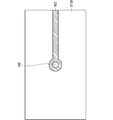
図1は、本実施の形態に関する高周波伝送線路層間接続の構成の例を概略的に示す断面図である。また、図2は、図1に例が示された高周波伝送線路層間接続の構成における層L1を示す断面図である。また、図3は、図1に例が示された高周波伝送線路層間接続の構成における層L2を示す断面図である。また、図4は、図1に例が示された高周波伝送線路層間接続の構成における層L3を示す断面図である。また、図5は、図1に例が示された高周波伝送線路層間接続の構成における層L4を示す断面図である。
図1は、本実施の形態に関する高周波伝送線路層間接続の構成の例を概略的に示す断面図である。また、図2は、図1に例が示された高周波伝送線路層間接続の構成における層L1を示す断面図である。また、図3は、図1に例が示された高周波伝送線路層間接続の構成における層L2を示す断面図である。また、図4は、図1に例が示された高周波伝送線路層間接続の構成における層L3を示す断面図である。また、図5は、図1に例が示された高周波伝送線路層間接続の構成における層L4を示す断面図である。
図1に例が示されるように、高周波伝送線路層間接続は、誘電体基板010と、誘電体基板010とは別の絶縁材である誘電体基板020とを備える。
誘電体基板010においては、図1に例が示されるように、層構造010Aの層L1に高周波伝送線路001が配置され、層構造010Aの層L2に高周波伝送線路002が配置される。層L2は、層構造010Aにおける層L1よりも層構造010Aの上面から遠い層である。また、図2に例が示されるように、高周波伝送線路001には信号線導体003が形成される。また、図3に例が示されるように、高周波伝送線路002には信号線導体004が形成される。ここで、誘電体基板010は、複数の誘電体が積層された構造である層構造010Aを備えており、図1に例が示される場合では、たとえば、層L2の下方に位置する層、層L2、層L2と層L1との間に位置する層、層L1、層L1と層L3との間に位置する層、および、層L3が積層されている。ただし、複数の誘電体層は、このような層の区切り方に限られるものではなく、たとえば、層L2の下方に位置する層が、さらに分割された複数の層からなる積層構造であると捉えることも可能である。
なお、層構造010Aは、たとえば、ガラスエポキシ樹脂(flame retardant type 4、すなわち、FR4)、ガラスコンポジット(composite epoxy material 3、すなわち、CEM3)などの低損失の繊維強化樹脂である。より具体的には、層構造010Aは、パナソニック社製のMEGTRON6などである。
また、図2および図3に例が示されるように、それぞれが異なる層に配置された信号線導体003と信号線導体004とは、柱状導体100によって接続されている。ここで、層構造010Aの上面から形成される柱状導体100は、少なくとも、層構造010Aにおける層L1および層L2に跨って形成される。また、信号線導体003および柱状導体100は、たとえば、銅である。
図4に例が示されるように、誘電体基板010の層L3には、導体パッド101が形成されている。また、導体パッド101は、柱状導体100に接続される。すなわち、柱状導体100は、誘電体基板010における層L1、層L2および層L3に跨って形成される。
誘電体基板020は、誘電体基板010の層L3から、接着または積層などの工程を経て形成される。また、図5に例が示されるように、誘電体基板020の層構造020Aの層L4にはグラウンド導体201(以下、グラウンド導体は、グラウンド電位または固定電位に設定される導体をいうものとする)が形成されている。そして、図4および図5に例が示されるように、柱状導体200によって、グラウンド導体201と導体パッド101とが接続されている。すなわち、柱状導体200は、層構造020Aにおける層L3と層構造020Aにおける層L4とに跨って形成される。
誘電体基板020は、層構造010Aの上面に形成され、かつ、柱状導体100に接続されることによって柱状導体100の上端を短絡させる。
ここで、図1に例が示されるように、信号線導体003と柱状導体100との接続部から、グラウンド導体201と柱状導体200との接続部までの距離901は、高周波伝送線路の所望周波数において4分の1波長の奇数倍とする。以上によって、誘電体多層基板における高周波伝送線路層間接続が形成される。
図6は、図1に例が示された構造における誘電体基板020が形成される前、すなわち、誘電体基板010のみの段階での構造の例を概略的に示す断面図である。
図6に例が示されるように、誘電体基板010の層L3に形成された導体パッド101は、グラウンド導体には接続されていない。また、導体パッド101は、層構造010Aの上面に露出して形成されている。
図1に例が示されたように、距離901の長さが所望周波数において4分の1波長の奇数倍であるため、信号線導体003と柱状導体100との接続部において、当該接続部からグラウンド導体201を見込んだ負荷が開放となる。そして、負荷が開放であることから、柱状導体100を介する信号線導体003と信号線導体004との接続において、不要な寄生成分が存在しない。
特に、図6に例が示されたように、誘電体基板010のみの構造である場合、柱状導体100の、信号線導体003と信号線導体004との間以外に位置する部分、すなわち、図1における、層構造010Aの層L1から層L3に渡る部分の柱状導体100は、先端開放スタブとなっているが、その不要な寄生成分も含めて、誘電体基板020に形成された先端短絡スタブによってキャンセルされる。
また、所望周波数において4分の1波長の長さの先端短絡スタブであるため、所望周波数の2倍高調波においては2分の1波長の長さの先端短絡スタブとなる。このことから、2倍高調波の抑圧用バンドリジェクションフィルターとして機能する。
また、図6に例が示されたように、誘電体基板010のみの構造である段階では、信号線導体に短絡箇所を含まない。そのため、電気検査を行うことが容易である。
電気検査では、信号線導体003から信号線導体004において、製造誤差に起因する短絡箇所の有無を判定することができる。また、電気検査では、抵抗値を測定することによって、柱状導体100と信号線導体003との間の接続不良、または、柱状導体100と信号線導体004との間の接続不良を確認することができる。
図7は、図1に例が示された構造における誘電体基板020が形成される前、すなわち、誘電体基板010Bのみの段階での構造の変形例を概略的に示す断面図である。
図7に例が示されるように、柱状導体100Aは、層構造010Aの上面から下面に達するように形成されている。さらに、柱状導体100Aの、層構造010Aの上面における導体パッド101に加えて、柱状導体100Aの、層構造010Aの下面における導体パッド101Aを備えていてもよい。
図7に例が示された構造によれば、上記で説明された効果に加え、信号線導体003と信号線導体004とにそれぞれ検査用導体パッドを設けなくても、柱状導体100Aの電気検査を行うことができるという効果が生じる。
図8は、本実施の形態に関する高周波伝送線路層間接続の構成の変形例を概略的に示す断面図である。
図8に例が示されるように、高周波伝送線路層間接続は、誘電体基板010と、フレキシブル基板030とを備える。図8に示されるように、図1における誘電体基板020は、薄い基板またはフレキシブル基板030に置き換えられてもよい。
フレキシブル基板030は、絶縁材料である層構造030Aと、層構造030Aの上面に形成されるグラウンド導体201Aとを備える。フレキシブル基板030は、たとえば、3Dプリンタなどを用いて形成された任意形状の絶縁材であってもよい。層構造030Aおよびグラウンド導体201Aは、平面視において導体パッド101に対応する位置に開口902が形成される。
グラウンド導体201Aと導体パッド101とは、はんだ301によって接続されている。はんだ301の代わりに、たとえば、金リボンまたはボンドワイヤーが用いられてもよい。グラウンド導体201Aおよびはんだ301は、銀ナノインクなどによってパターニングされていてもよい。
信号線導体003と柱状導体100との接続部から、グラウンド導体201Aまでの距離901は、高周波伝送線路の所望周波数において4分の1波長の奇数倍とする。
図8に例が示された構造によれば、柱状導体100を介する信号線導体003と信号線導体004との接続において、不要な寄生成分が存在しない。また、誘電体基板010の構造において、信号線導体に短絡箇所を含まない。そのため、電気検査を行うことが容易である。
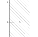
図9は、本実施の形態に関する高周波伝送線路層間接続の構成の変形例を概略的に示す断面図である。また、図10は、図9に例が示された構成の上面図である。
図9に例が示されるように、高周波伝送線路層間接続は、誘電体基板010を備える。図9および図10に示されるように、図1における誘電体基板020は、備えられなくてもよい。
誘電体基板010の層構造010Aの上面には、グラウンド導体201Bが形成される。グラウンド導体201Bは、平面視において導体パッド101に対応する位置に開口が形成される。また、グラウンド導体201Bと導体パッド101に跨って、0Ωチップ抵抗器302が形成されている。
0Ωチップ抵抗器302は、たとえば、金リボン、ボンドワイヤーまたははんだなどの導通を確保することができる構成に置き換えられてもよい。
信号線導体003と柱状導体100との接続部から、グラウンド導体201Bまでの距離901は、高周波伝送線路の所望周波数において4分の1波長の奇数倍とする。
図9に例が示された構造によれば、柱状導体100を介する信号線導体003と信号線導体004との接続において、不要な寄生成分が存在しない。また、誘電体基板010の構造において、信号線導体に短絡箇所を含まない。そのため、電気検査を行うことが容易である。
図11は、本実施の形態に関する高周波伝送線路層間接続の構成の変形例を概略的に示す断面図である。
図11に例が示されるように、高周波伝送線路層間接続は、誘電体基板010と、誘電体基板020Cとを備える。図11に示されるように、誘電体基板020Cは、層構造020Aと、層構造020Aの上面に形成されたグラウンド導体201Cとを備える。
グラウンド導体201Cの柱状導体200と接続される部分は、グラウンド導体201Cの他の部分と離間して形成されている。また、グラウンド導体201Cの柱状導体200と接続される部分と、グラウンド導体201Cの他の部分とは、それらに跨って形成される0Ωチップ抵抗器302によって接続される。0Ωチップ抵抗器302は、たとえば、金リボン、ボンドワイヤーまたははんだなどの導通を確保することができる構成に置き換えられてもよい。
図11に例が示された構造によれば、誘電体基板020Cが形成された後、すなわち、誘電体多層基板の構造が完成した後に、電気検査を実施することができる。
図12は、本実施の形態に関する高周波伝送線路層間接続の構成の変形例を概略的に示す断面図である。
図12に例が示されるように、高周波伝送線路層間接続は、誘電体基板010と、誘電体基板020Dとを備える。図12に示されるように、誘電体基板020Dは、層構造020Aと、層構造020Aの上面に形成されたグラウンド導体201Dとを備える。
グラウンド導体201Dの柱状導体200と接続される部分は、グラウンド導体201Dの他の部分と離間して形成されている。また、グラウンド導体201Dの柱状導体200と接続される部分と、グラウンド導体201Dの他の部分とに跨って覆う、はんだ1000が形成されている。
図12に例が示された構造によれば、誘電体基板020Dが形成された後、すなわち、誘電体多層基板の構造が完成した後に、電気検査を実施することができる。
図13は、本実施の形態に関する高周波伝送線路層間接続の構成の変形例を概略的に示す断面図である。
図13に例が示されるように、高周波伝送線路層間接続は、誘電体基板010Cを備える。図13に示されるように、図1における誘電体基板020は、備えられなくてもよい。
誘電体基板010Cの層構造010Aの上面には、グラウンド導体201Eが形成される。グラウンド導体201Eは、平面視において導体パッド101Cに対応する位置に開口が形成される。また、グラウンド導体201Eと導体パッド101Cに跨って、0Ωチップ抵抗器302が形成されている。
0Ωチップ抵抗器302は、たとえば、金リボン、ボンドワイヤーまたははんだなどの導通を確保することができる構成に置き換えられてもよい。
図13に例が示されるように、柱状導体100Cは、層構造010Aの上面から下面に達するように形成されている。さらに、柱状導体100Cの、層構造010Aの上面における導体パッド101Cに加えて、柱状導体100Cの、層構造010Aの下面における導体パッド102が備えられる。
また、柱状導体100Cは、リード挿入部品または圧入部品の実装穴を兼ねる。図13では、柱状導体100C内に挿入部品303が挿入されている。
信号線導体003と柱状導体100Cとの接続部から、グラウンド導体201Eまでの距離901は、高周波伝送線路の所望周波数において4分の1波長の奇数倍とする。
図13に例が示された構造によれば、柱状導体100Cを介する信号線導体003の接続において、不要な寄生成分が存在しない。また、誘電体基板010Cの構造において、信号線導体に短絡箇所を含まない。そのため、電気検査を行うことが容易である。
<第2の実施の形態>
本実施の形態に関する信号伝送構造、信号伝送構造の製造方法、および、高周波信号送受信装置について説明する。以下の説明においては、以上に記載された実施の形態で説明された構成要素と同様の構成要素については同じ符号を付して図示し、その詳細な説明については適宜省略するものとする。
本実施の形態に関する信号伝送構造、信号伝送構造の製造方法、および、高周波信号送受信装置について説明する。以下の説明においては、以上に記載された実施の形態で説明された構成要素と同様の構成要素については同じ符号を付して図示し、その詳細な説明については適宜省略するものとする。
<信号伝送構造の構成について>
図14は、本実施の形態に関する高周波伝送線路層間接続の構成の例を概略的に示す断面図である。また、図15は、図14に例が示された高周波伝送線路層間接続の構成における層L1を示す断面図である。また、図16は、図14に例が示された高周波伝送線路層間接続の構成における層L2を示す断面図である。また、図17は、図14に例が示された高周波伝送線路層間接続の構成における層L3を示す断面図である。また、図18は、図14に例が示された高周波伝送線路層間接続の構成における層L4を示す断面図である。
図14は、本実施の形態に関する高周波伝送線路層間接続の構成の例を概略的に示す断面図である。また、図15は、図14に例が示された高周波伝送線路層間接続の構成における層L1を示す断面図である。また、図16は、図14に例が示された高周波伝送線路層間接続の構成における層L2を示す断面図である。また、図17は、図14に例が示された高周波伝送線路層間接続の構成における層L3を示す断面図である。また、図18は、図14に例が示された高周波伝送線路層間接続の構成における層L4を示す断面図である。
図14に例が示されるように、高周波伝送線路層間接続は、誘電体基板010Eと、誘電体基板010Eとは別の絶縁材である誘電体基板020Eとを備える。誘電体基板020Eは、誘電体基板010Eの上面および下面の双方に配置されている。
誘電体基板010Eにおいては、図14に例が示されるように、層構造010Aの層L1に高周波伝送線路001が配置され、層構造010Aの層L2に高周波伝送線路002が配置される。また、図15に例が示されるように、高周波伝送線路001には信号線導体003が形成される。また、図16に例が示されるように、高周波伝送線路002には信号線導体004が形成される。
高周波伝送線路001は、信号線導体003と、信号線導体003の上下の層に配置されるグラウンド導体005とから構成されるストリップ線路である。
高周波伝送線路002は、信号線導体004と、信号線導体004の上下の層に配置されるグラウンド導体005とから構成されるストリップ線路である。
また、図15および図16に例が示されるように、それぞれが異なる層に配置された信号線導体003と信号線導体004とは、柱状導体100Eによって接続されている。ここで、柱状導体100Eは、少なくとも、層構造010Aにおける層L1および層L2に跨って形成される。
図17に例が示されるように、誘電体基板010Eの層L3には、導体パッド101が形成されている。また、導体パッド101は、柱状導体100Eに接続される。すなわち、柱状導体100Eは、誘電体基板010Eにおける層L1、層L2および層L3に跨って形成される。
誘電体基板020Eは、誘電体基板010Eの層L3から、接着または積層などの工程を経て形成される。また、図18に例が示されるように、誘電体基板020Eの層構造020Aの層L4にはグラウンド導体201が形成されている。そして、図17および図18に例が示されるように、柱状導体200によって、グラウンド導体201と導体パッド101とが接続されている。すなわち、柱状導体200は、層構造020Aにおける層L3と層構造020Aにおける層L4とに跨って形成される。
ここで、図14に例が示されるように、信号線導体003と柱状導体100Eとの接続部から、グラウンド導体201と柱状導体200との接続部までの距離901は、高周波伝送線路の所望周波数において4分の1波長の奇数倍とする。以上によって、誘電体多層基板における高周波伝送線路層間接続が形成される。
図19は、図14に例が示された構造におけるそれぞれの誘電体基板020Eが形成される前、すなわち、誘電体基板010Eのみの段階での構造の例を概略的に示す断面図である。
図19に例が示されるように、誘電体基板010Eの層L3に形成された導体パッド101は、グラウンド導体には接続されていない。また、導体パッド101は、層構造010Aの上面に露出して形成されている。
本実施の形態に関する構造によれば、柱状導体100Eを介する信号線導体003と信号線導体004との接続において、不要な寄生成分が存在しない。また、誘電体基板010Eの構造において、信号線導体に短絡箇所を含まない。そのため、電気検査を行うことが容易である。
また、伝送線路の構造が、高周波伝送線路001と高周波伝送線路002とで同一とすることができるため、設計を簡略化し、かつ、インピーダンスミスマッチを抑制することができる。よって、より広帯域の信号を通過させることができる。
さらに、伝送線路がストリップ線路から構成されるため、他の層に配置された回路との不要な結合を抑圧することができる。
<第3の実施の形態>
本実施の形態に関する信号伝送構造、信号伝送構造の製造方法、および、高周波信号送受信装置について説明する。以下の説明においては、以上に記載された実施の形態で説明された構成要素と同様の構成要素については同じ符号を付して図示し、その詳細な説明については適宜省略するものとする。
本実施の形態に関する信号伝送構造、信号伝送構造の製造方法、および、高周波信号送受信装置について説明する。以下の説明においては、以上に記載された実施の形態で説明された構成要素と同様の構成要素については同じ符号を付して図示し、その詳細な説明については適宜省略するものとする。
<信号伝送構造の構成について>
図20は、本実施の形態に関する高周波伝送線路層間接続の構成の例を概略的に示す断面図である。また、図21は、図20に例が示された高周波伝送線路層間接続の構成における層L1を示す断面図である。また、図22は、図20に例が示された高周波伝送線路層間接続の構成における層L2を示す断面図である。また、図23は、図20に例が示された高周波伝送線路層間接続の構成における層L3を示す断面図である。また、図24は、図20に例が示された高周波伝送線路層間接続の構成における層L4を示す断面図である。
図20は、本実施の形態に関する高周波伝送線路層間接続の構成の例を概略的に示す断面図である。また、図21は、図20に例が示された高周波伝送線路層間接続の構成における層L1を示す断面図である。また、図22は、図20に例が示された高周波伝送線路層間接続の構成における層L2を示す断面図である。また、図23は、図20に例が示された高周波伝送線路層間接続の構成における層L3を示す断面図である。また、図24は、図20に例が示された高周波伝送線路層間接続の構成における層L4を示す断面図である。
図20に例が示されるように、高周波伝送線路層間接続は、誘電体基板010Fと、誘電体基板010Fとは別の絶縁材である誘電体基板020Fとを備える。誘電体基板020Fは、誘電体基板010Fの上面および下面の双方に配置されている。
誘電体基板010Fにおいては、図20に例が示されるように、層構造010Aの層L1に高周波伝送線路001が配置され、層構造010Aの層L2に高周波伝送線路002が配置される。また、図21に例が示されるように、高周波伝送線路001には信号線導体003が形成される。また、図22に例が示されるように、高周波伝送線路002には信号線導体004が形成される。
高周波伝送線路001は、信号線導体003と、信号線導体003の上下の層に配置されるグラウンド導体005とから構成されるストリップ線路である。
高周波伝送線路002は、信号線導体004と、信号線導体004の上下の層に配置されるグラウンド導体005とから構成されるストリップ線路である。
また、図21および図22に例が示されるように、それぞれが異なる層に配置された信号線導体003と信号線導体004とは、柱状導体100Fによって接続されている。ここで、柱状導体100Fは、少なくとも、層構造010Aにおける層L1および層L2に跨って形成される。
図23に例が示されるように、誘電体基板010Fの層L3には、導体パッド101が形成されている。また、導体パッド101は、柱状導体100Fに接続される。すなわち、柱状導体100Fは、誘電体基板010Fにおける層L1、層L2および層L3に跨って形成される。
誘電体基板020Fは、誘電体基板010Fの層L3から、接着または積層などの工程を経て形成される。また、図24に例が示されるように、誘電体基板020Fの層構造020Aの層L4にはグラウンド導体201が形成されている。そして、図23および図24に例が示されるように、柱状導体200によって、グラウンド導体201と導体パッド101とが接続されている。すなわち、柱状導体200は、層構造020Aにおける層L3と層構造020Aにおける層L4とに跨って形成される。
誘電体基板010Fにおいては、信号線導体003、および、それぞれの層のグラウンド導体005を接続する複数の柱状導体300が配置されている。
また、誘電体基板020Fにおいては、グラウンド導体201とグラウンド導体005とを接続する複数の柱状導体400が配置されている。
柱状導体300は、図21、図22および図23に示されるように、平面視において、信号線導体003、信号線導体004、柱状導体100F、導体パッド101および柱状導体200を囲んで配列されている。柱状導体300は、図21に示されるように、配列間隔903で配列されている。
また、柱状導体400は、図23および図24に示されるように、平面視において、信号線導体003、信号線導体004、柱状導体100F、導体パッド101および柱状導体200を囲んで配列されている。柱状導体400は、図24に示されるように、配列間隔904で配列されている。
ここで、配列間隔903および配列間隔904は、所望信号において2分の1波長以下である。
また、図20に例が示されるように、信号線導体003と柱状導体100Fとの接続部から、グラウンド導体201と柱状導体200との接続部までの距離901は、高周波伝送線路の所望周波数において4分の1波長の奇数倍とする。以上によって、誘電体多層基板における高周波伝送線路層間接続が形成される。
図25は、図20に例が示された構造におけるそれぞれの誘電体基板020Fが形成される前、すなわち、誘電体基板010Fのみの段階での構造の例を概略的に示す断面図である。
図25に例が示されるように、誘電体基板010Fの層L3に形成された導体パッド101は、グラウンド導体には接続されていない。また、導体パッド101は、層構造010Aの上面に露出して形成されている。
本実施の形態に関する構造によれば、柱状導体100Fを介する信号線導体003と信号線導体004との接続において、不要な寄生成分が存在しない。また、誘電体基板010Fの構造において、信号線導体に短絡箇所を含まない。そのため、電気検査を行うことが容易である。
また、信号線導体および短絡スタブが、平面視においてすべて柱状導体に囲われて位置し、さらに、柱状導体同士の間の間隔が、所望周波数において2分の1波長以下であるため、層間接続部または短絡部における不要な電磁波の放射を抑えることができる。
<第4の実施の形態>
本実施の形態に関する信号伝送構造、信号伝送構造の製造方法、および、高周波信号送受信装置について説明する。以下の説明においては、以上に記載された実施の形態で説明された構成要素と同様の構成要素については同じ符号を付して図示し、その詳細な説明については適宜省略するものとする。
本実施の形態に関する信号伝送構造、信号伝送構造の製造方法、および、高周波信号送受信装置について説明する。以下の説明においては、以上に記載された実施の形態で説明された構成要素と同様の構成要素については同じ符号を付して図示し、その詳細な説明については適宜省略するものとする。
<信号伝送構造の構成について>
図26は、本実施の形態に関する高周波伝送線路層間接続の構成の例を概略的に示す断面図である。また、図27は、図26に例が示された高周波伝送線路層間接続の構成における層L1を示す断面図である。また、図28は、図26に例が示された高周波伝送線路層間接続の構成における層L2を示す断面図である。また、図29は、図26に例が示された高周波伝送線路層間接続の構成における層L3を示す断面図である。また、図30は、図26に例が示された高周波伝送線路層間接続の構成における層L4を示す断面図である。
図26は、本実施の形態に関する高周波伝送線路層間接続の構成の例を概略的に示す断面図である。また、図27は、図26に例が示された高周波伝送線路層間接続の構成における層L1を示す断面図である。また、図28は、図26に例が示された高周波伝送線路層間接続の構成における層L2を示す断面図である。また、図29は、図26に例が示された高周波伝送線路層間接続の構成における層L3を示す断面図である。また、図30は、図26に例が示された高周波伝送線路層間接続の構成における層L4を示す断面図である。
図26に例が示されるように、高周波伝送線路層間接続は、誘電体基板010Gと、誘電体基板010Gとは別の絶縁材である誘電体基板020Fとを備える。誘電体基板020Fは、誘電体基板010Gの上面および下面の双方に配置されている。
本実施の形態に関する構成は、信号線導体004から信号線導体006と信号線導体007とに2分岐する分配回路と、第1の実施の形態、第2の実施の形態および第3の実施の形態に示された高周波伝送線路層間接続構造とを併せ持つ構造である。
誘電体基板010Gにおいては、図26に例が示されるように、層構造010Aの層L1に高周波伝送線路001が配置され、層構造010Aの層L2に高周波伝送線路002が配置される。また、図27に例が示されるように、高周波伝送線路001には信号線導体007および信号線導体006が、ともに柱状導体100Gに接続されて形成される。また、図28に例が示されるように、高周波伝送線路002には信号線導体004が形成される。
また、図27および図28に例が示されるように、それぞれが異なる層に配置された信号線導体007、信号線導体006および信号線導体004は、柱状導体100Gによって接続されている。ここで、柱状導体100Gは、少なくとも、層構造010Aにおける層L1および層L2に跨って形成される。
図29に例が示されるように、誘電体基板010Gの層L3には、導体パッド101が形成されている。また、導体パッド101は、柱状導体100Gに接続される。すなわち、柱状導体100Gは、誘電体基板010Gにおける層L1、層L2および層L3に跨って形成される。
誘電体基板010Gにおいては、信号線導体、および、それぞれの層のグラウンド導体005を接続する複数の柱状導体300が配置されている。
柱状導体300は、図27、図28および図29に示されるように、平面視において、信号線導体007、信号線導体006、信号線導体004、柱状導体100G、導体パッド101および柱状導体200を囲んで配列されている。柱状導体300は、図27に示されるように、配列間隔903で配列されている。
また、柱状導体400は、図29および図30に示されるように、平面視において、信号線導体007、信号線導体006、信号線導体004、柱状導体100G、導体パッド101および柱状導体200を囲んで配列されている。柱状導体400は、図30に示されるように、配列間隔904で配列されている。
ここで、図26に例が示されるように、信号線導体006と柱状導体100Gとの接続部から、グラウンド導体201と柱状導体200との接続部までの距離901は、高周波伝送線路の所望周波数において4分の1波長の奇数倍とする。以上によって、誘電体多層基板における高周波伝送線路層間接続が形成される。
図31は、図26に例が示された構造におけるそれぞれの誘電体基板020Fが形成される前、すなわち、誘電体基板010Gのみの段階での構造の例を概略的に示す断面図である。
図31に例が示されるように、誘電体基板010Gの層L3に形成された導体パッド101は、グラウンド導体には接続されていない。また、導体パッド101は、層構造010Aの上面に露出して形成されている。
本実施の形態に関する構造によれば、2分岐の分配回路と高周波伝送線路間接続構造とを併せ持つ構造であることによって、双方の機能を有する装置としての小形化を実現することができる。
すなわち、柱状導体100Gからなる部分を高周波伝送線路と捉え、そのインピーダンスに適切に整合されるよう信号線導体006および信号線導体007を配置すれば、通常の平面回路のみで形成される2分岐回路の一部が、柱状導体100Gから構成されることになるため、装置の小形化を実現することができる。
<以上に記載された実施の形態によって生じる効果について>
次に、以上に記載された実施の形態によって生じる効果の例を示す。なお、以下の説明においては、以上に記載された実施の形態に例が示された具体的な構成に基づいて当該効果が記載されるが、同様の効果が生じる範囲で、本願明細書に例が示される他の具体的な構成と置き換えられてもよい。
次に、以上に記載された実施の形態によって生じる効果の例を示す。なお、以下の説明においては、以上に記載された実施の形態に例が示された具体的な構成に基づいて当該効果が記載されるが、同様の効果が生じる範囲で、本願明細書に例が示される他の具体的な構成と置き換えられてもよい。
また、当該置き換えは、複数の実施の形態に跨ってなされてもよい。すなわち、異なる実施の形態において例が示されたそれぞれの構成が組み合わされて、同様の効果が生じる場合であってもよい。
以上に記載された実施の形態によれば、信号伝送構造は、第1の信号線導体と、第2の信号線導体と、第1の柱状導体とを備える。ここで、第1の信号線導体は、たとえば、信号線導体003に対応するものである。また、第2の信号線導体は、たとえば、信号線導体004に対応するものである。また、第1の柱状導体は、たとえば、柱状導体100に対応するものである。信号線導体003は、複数の層からなる誘電体層における第1の層に形成される。ここで、誘電体層は、たとえば、層構造010Aに対応するものである。また、第1の層は、たとえば、層L1に対応するものである。信号線導体004は、層構造010Aにおける層L1よりも層構造010Aの上面から遠い層である第2の層に形成される。ここで、第2の層は、たとえば、層L2に対応するものである。柱状導体100は、層構造010Aの上面から、信号線導体003を介して信号線導体004まで達して形成される。そして、短絡構造から、短絡構造に接続される柱状導体100を介して、柱状導体100と信号線導体003との接続部までの長さ(たとえば、図1における距離901)が、信号線導体003、柱状導体100および信号線導体004において伝送される信号の波長の4分の1の奇数倍である。ここで、短絡構造は、たとえば、誘電体基板020を含む構造に対応するものである。また、誘電体基板020は、層構造010Aの上面に形成され、かつ、柱状導体100に接続されることによって柱状導体100の上端を短絡させる構造である。
このような構成によれば、層構造010Aの上面における柱状導体100を用いて適切に電気検査をすることができる。また、層構造010Aの上面に誘電体基板020が形成された状態では、柱状導体100に長さが信号の波長の4分の1の奇数倍の短絡スタブが形成されるため、寄生成分による特性劣化を抑制することができる。
なお、これらの構成以外の本願明細書に例が示される他の構成については適宜省略することができる。すなわち、少なくともこれらの構成を備えていれば、以上に記載された効果を生じさせることができる。
しかしながら、本願明細書に例が示される他の構成のうちの少なくとも1つを、以上に記載された構成に適宜追加した場合、すなわち、以上に記載された構成としては言及されなかった本願明細書に例が示される他の構成が適宜追加された場合であっても、同様の効果を生じさせることができる。
また、以上に記載された実施の形態によれば、第1の柱状導体は、誘電体層の下面にも達して形成される。ここで、第1の柱状導体は、たとえば、柱状導体100Aに対応するものである。また、誘電体層は、たとえば、誘電体基板010Bに対応するものである。このような構成によれば、信号線導体003と信号線導体004とにそれぞれ検査用導体パッドを設けなくても、柱状導体100Aの電気検査を行うことができる。
また、以上に記載された実施の形態によれば、短絡構造は、第1のグラウンド導体と、第1のグラウンド導体と柱状導体100とを接続する接続部とを備える。ここで、第1のグラウンド導体は、たとえば、グラウンド導体201に対応するものである。このような構成によれば、柱状導体100を介する信号線導体003と信号線導体004との接続において、不要な寄生成分が存在しない。また、誘電体基板010の構造において、信号線導体に短絡箇所を含まない。
また、以上に記載された実施の形態によれば、接続部は、はんだ301である。このような構成によれば、柱状導体100を介する信号線導体003と信号線導体004との接続において、不要な寄生成分が存在しない。また、誘電体基板010の構造において、信号線導体に短絡箇所を含まない。
また、以上に記載された実施の形態によれば、接続部は、チップ抵抗器302である。このような構成によれば、柱状導体100を介する信号線導体003と信号線導体004との接続において、不要な寄生成分が存在しない。また、誘電体基板010の構造において、信号線導体に短絡箇所を含まない。
また、以上に記載された実施の形態によれば、接続部は、第2の柱状導体である。ここで、第2の柱状導体は、たとえば、柱状導体200に対応するものである。このような構成によれば、柱状導体100を介する信号線導体003と信号線導体004との接続において、不要な寄生成分が存在しない。また、誘電体基板010の構造において、信号線導体に短絡箇所を含まない。
また、以上に記載された実施の形態によれば、信号伝送構造は、第2のグラウンド導体と、第3のグラウンド導体とを備える。ここで、第2のグラウンド導体は、たとえば、層L1の信号線導体003を層L1の上下層において挟んで配置されるグラウンド導体005に対応するものである。また、第3のグラウンド導体は、たとえば、層L2の信号線導体004を層L2の上下層において挟んで配置されるグラウンド導体005に対応するものである。このような構成によれば、伝送線路がストリップ線路から構成されるため、他の層に配置された回路との不要な結合を抑圧することができる。
また、以上に記載された実施の形態によれば、信号伝送構造は、少なくとも1つの第2の柱状導体と、少なくとも1つの第3の柱状導体とを備える。ここで、第2の柱状導体は、たとえば、信号線導体003と、信号線導体003を挟んで配置されるグラウンド導体005とを接続する柱状導体300に対応するものである。また、第2の柱状導体は、たとえば、信号線導体004と、信号線導体004を挟んで配置されるグラウンド導体005とを接続する柱状導体300に対応するものである。そして、柱状導体300同士の隣り合う間隔が、信号線導体003、柱状導体100Fおよび信号線導体004において伝送される信号の波長の半分以下である。また、柱状導体400同士の隣り合う間隔も、信号線導体003、柱状導体100Fおよび信号線導体004において伝送される信号の波長の半分以下である。このような構成によれば、信号線導体および短絡スタブが、平面視においてすべて柱状導体に囲われて位置し、さらに、柱状導体同士の間の間隔が、所望周波数において2分の1波長以下であるため、層間接続部または短絡部における不要な電磁波の放射を抑えることができる。
また、以上に記載された実施の形態によれば、信号伝送構造は、層L1に形成され、かつ、柱状導体100に接続される第3の信号線導体を備える。ここで、第3の信号線導体は、たとえば、信号線導体007に対応するものである。このような構成によれば、信号線導体004から信号線導体006と信号線導体007とに2分岐する分配回路と、高周波伝送線路層間接続構造とを併せ持つ構造を実現することができる。そのため、柱状導体100Gからなる部分を高周波伝送線路と捉え、そのインピーダンスに適切に整合されるよう信号線導体006および信号線導体007を配置すれば、通常の平面回路のみで形成される2分岐回路の一部が、柱状導体100Gから構成されることになるため、装置の小形化を実現することができる。
また、以上に記載された実施の形態によれば、高周波信号送受信装置は、上記の信号伝送構造を備える。このような構成によれば、層構造010Aの上面における柱状導体100を用いて適切に電気検査をすることができる。また、層構造010Aの上面に誘電体基板020が形成された状態では、柱状導体100に長さが信号の波長の4分の1の奇数倍の短絡スタブが形成されるため、寄生成分による特性劣化を抑制することができる。
以上に記載された実施の形態によれば、信号伝送構造の製造方法において、複数の層からなる層構造010Aにおける層L1に信号線導体003を形成する。そして、層構造010Aにおける層L1よりも層構造010Aの上面から遠い層である層L2に、信号線導体004を形成する。そして、層構造010Aの上面から、信号線導体003を介して信号線導体004まで達する、柱状導体100を形成する。そして、層構造010Aの上面における柱状導体100を用いて、電気検査を行う。そして、電気検査の後に、柱状導体100の上端を短絡させる誘電体基板020を層構造010Aの上面に形成する。ここで、誘電体基板020から、誘電体基板020に接続される柱状導体100を介して、柱状導体100と信号線導体003との接続部までの長さ(たとえば、図1における距離901)が、信号線導体003、柱状導体100および信号線導体004において伝送される信号の波長の4分の1の奇数倍である。
このような構成によれば、誘電体基板020が形成される前の工程において、層構造010Aの上面における柱状導体100を用いて適切に電気検査をすることができる。また、層構造010Aの上面に誘電体基板020が形成された後の状態では、柱状導体100に長さが信号の波長の4分の1の奇数倍の短絡スタブが形成されるため、寄生成分による特性劣化を抑制することができる。
なお、これらの構成以外の本願明細書に例が示される他の構成については適宜省略することができる。すなわち、少なくともこれらの構成を備えていれば、以上に記載された効果を生じさせることができる。
しかしながら、本願明細書に例が示される他の構成のうちの少なくとも1つを、以上に記載された構成に適宜追加した場合、すなわち、以上に記載された構成としては言及されなかった本願明細書に例が示される他の構成が適宜追加された場合であっても、同様の効果を生じさせることができる。
また、特段の制限がない場合には、それぞれの処理が行われる順序は変更することができる。
<以上に記載された実施の形態における変形例について>
以上に記載された実施の形態では、それぞれの構成要素の材質、材料、寸法、形状、相対的配置関係または実施の条件などについても記載する場合があるが、これらはすべての局面においてひとつの例であって、本願明細書に記載されたものに限られることはないものとする。
以上に記載された実施の形態では、それぞれの構成要素の材質、材料、寸法、形状、相対的配置関係または実施の条件などについても記載する場合があるが、これらはすべての局面においてひとつの例であって、本願明細書に記載されたものに限られることはないものとする。
したがって、例が示されていない無数の変形例、および、均等物が、本願明細書に開示される技術の範囲内において想定される。たとえば、少なくとも1つの構成要素を変形する場合、追加する場合または省略する場合、さらには、少なくとも1つの実施の形態における少なくとも1つの構成要素を抽出し、他の実施の形態の構成要素と組み合わせる場合が含まれるものとする。
また、矛盾が生じない限り、以上に記載された実施の形態において「1つ」備えられるものとして記載された構成要素は、「1つ以上」備えられていてもよいものとする。
さらに、以上に記載された実施の形態におけるそれぞれの構成要素は概念的な単位であって、本願明細書に開示される技術の範囲内には、1つの構成要素が複数の構造物から成る場合と、1つの構成要素がある構造物の一部に対応する場合と、さらには、複数の構成要素が1つの構造物に備えられる場合とを含むものとする。
また、以上に記載された実施の形態におけるそれぞれの構成要素には、同一の機能を発揮する限り、他の構造または形状を有する構造物が含まれるものとする。
また、本願明細書における説明は、本技術に関するすべての目的のために参照され、いずれも、従来技術であると認めるものではない。
また、以上に記載された実施の形態において、特に指定されずに材料名などが記載された場合は、矛盾が生じない限り、当該材料に他の添加物が含まれた、たとえば、合金などが含まれるものとする。
001,002 高周波伝送線路、003,004,006,007 信号線導体、005,201,201A,201B,201C,201D,201E グラウンド導体、010,010B,010C,010E,010F,010G,020,020C,020D,020E,020F 誘電体基板、010A,020A,030A 層構造、030 フレキシブル基板、100,100A,100C,100E,100F,100G,200,300,400 柱状導体、101,101A,101C,102 導体パッド、301,1000 はんだ、302 チップ抵抗器、303 挿入部品、901 距離、902 開口、903,904 配列間隔。
Claims (14)
- 複数の層からなる誘電体層(010A)における第1の層(L1)に形成される第1の信号線導体(003)と、
前記誘電体層(010A)における前記第1の層(L1)よりも前記誘電体層(010A)の上面から遠い層である第2の層(L2)に形成される第2の信号線導体(004)と、
前記誘電体層(010A)の上面から、前記第1の信号線導体(003)を介して前記第2の信号線導体(004)まで達して形成される第1の柱状導体(100)とを備え、
前記誘電体層(010A)の上面に形成され、かつ、前記第1の柱状導体(100)の上端を短絡させる短絡構造(020)から、前記短絡構造(020)に接続される前記第1の柱状導体(100)を介して、前記第1の柱状導体(100)と前記第1の信号線導体(003)との接続部までの長さ(901)が、前記第1の信号線導体(003)、前記第1の柱状導体(100)および前記第2の信号線導体(004)において伝送される信号の波長の4分の1の奇数倍である、
信号伝送構造。 - 前記第1の柱状導体(100A)は、前記誘電体層(010B)の下面にも達して形成される、
請求項1に記載の信号伝送構造。 - 前記短絡構造は、
第1のグラウンド導体(201、201A、201B、201C、201D、201E)と、
前記第1のグラウンド導体(201、201A、201B、201C、201D、201E)と前記第1の柱状導体(100、100C)とを接続する接続部(101、200、301、302、1000、101C)とを備える、
請求項1または請求項2に記載の信号伝送構造。 - 前記接続部は、はんだ(301、1000)である、
請求項3に記載の信号伝送構造。 - 前記接続部は、チップ抵抗器(302)である、
請求項3に記載の信号伝送構造。 - 前記接続部は、第2の柱状導体(200)である、
請求項3に記載の信号伝送構造。 - 前記第1の層(L1)よりも前記誘電体層(010A)の上面に近い層、および、前記第1の層(L1)よりも前記誘電体層(010A)の上面から遠い層において形成される、第2のグラウンド導体(005)と、
前記第2の層(L2)よりも前記誘電体層(010A)の上面に近い層、および、前記第2の層(L2)よりも前記誘電体層(010A)の上面から遠い層において形成される、第3のグラウンド導体(005)とをさらに備える、
請求項1から請求項6のうちのいずれか1項に記載の信号伝送構造。 - 前記第1の信号線導体(003)と、前記第1の信号線導体(003)を挟んで配置される前記第2のグラウンド導体(005)とを接続する、少なくとも1つの第2の柱状導体(300)と、
前記第2の信号線導体(004)と、前記第2の信号線導体(004)を挟んで配置される前記第3のグラウンド導体(005)とを接続する、少なくとも1つの第3の柱状導体(300)とをさらに備え、
前記第2の柱状導体(300)および前記第3の柱状導体(300)のうちの隣り合う間隔が、前記第1の信号線導体(003)、前記第1の柱状導体(100)および前記第2の信号線導体(004)において伝送される信号の波長の半分以下である、
請求項7に記載の信号伝送構造。 - 前記第1の層(L1)に形成され、かつ、前記第1の柱状導体(100)に接続される第3の信号線導体(007)をさらに備える、
請求項1から請求項8のうちのいずれか1項に記載の信号伝送構造。 - 請求項1から請求項9のうちのいずれか1項に記載の信号伝送構造を備える、
高周波信号送受信装置。 - 複数の層からなる誘電体層(010A)における第1の層(L1)に第1の信号線導体(003)を形成し、
前記誘電体層(010A)における前記第1の層(L1)よりも前記誘電体層(010A)の上面から遠い層である第2の層(L2)に、第2の信号線導体(004)を形成し、
前記誘電体層(010A)の上面から、前記第1の信号線導体(003)を介して前記第2の信号線導体(004)まで達する、第1の柱状導体(100)を形成し、
前記誘電体層(010A)の上面における前記第1の柱状導体(100)を用いて、電気検査を行い、
前記電気検査の後に、前記第1の柱状導体(100)の上端を短絡させる短絡構造(020)を前記誘電体層(010A)の上面に形成し、
前記短絡構造(020)から、前記短絡構造(020)に接続される前記第1の柱状導体(100)を介して、前記第1の柱状導体(100)と前記第1の信号線導体(003)との接続部までの長さ(901)が、前記第1の信号線導体(003)、前記第1の柱状導体(100)および前記第2の信号線導体(004)において伝送される信号の波長の4分の1の奇数倍である、
信号伝送構造の製造方法。 - 前記短絡構造は、
第1のグラウンド導体(201、201A、201B、201C、201D、201E)と、
前記第1のグラウンド導体(201、201A、201B、201C、201D、201E)と前記第1の柱状導体(100、100C)とを接続する接続部(101、200、301、302、1000、101C)とを備える、
請求項11に記載の信号伝送構造の製造方法。 - 前記第1の層(L1)よりも前記誘電体層(010A)の上面に近い層、および、前記第1の層(L1)よりも前記誘電体層(010A)の上面から遠い層において形成される、第2のグラウンド導体(005)と、
前記第2の層(L2)よりも前記誘電体層(010A)の上面に近い層、および、前記第2の層(L2)よりも前記誘電体層(010A)の上面から遠い層において形成される、第3のグラウンド導体(005)とをさらに備える、
請求項11または請求項12に記載の信号伝送構造の製造方法。 - 前記第1の層(L1)に形成され、かつ、前記第1の柱状導体(100)に接続される第3の信号線導体(007)をさらに備える、
請求項11から請求項13のうちのいずれか1項に記載の信号伝送構造の製造方法。
Priority Applications (1)
| Application Number | Priority Date | Filing Date | Title |
|---|---|---|---|
| PCT/JP2018/018734 WO2019220530A1 (ja) | 2018-05-15 | 2018-05-15 | 信号伝送構造、信号伝送構造の製造方法、および、高周波信号送受信装置 |
Applications Claiming Priority (1)
| Application Number | Priority Date | Filing Date | Title |
|---|---|---|---|
| PCT/JP2018/018734 WO2019220530A1 (ja) | 2018-05-15 | 2018-05-15 | 信号伝送構造、信号伝送構造の製造方法、および、高周波信号送受信装置 |
Publications (1)
| Publication Number | Publication Date |
|---|---|
| WO2019220530A1 true WO2019220530A1 (ja) | 2019-11-21 |
Family
ID=68539829
Family Applications (1)
| Application Number | Title | Priority Date | Filing Date |
|---|---|---|---|
| PCT/JP2018/018734 WO2019220530A1 (ja) | 2018-05-15 | 2018-05-15 | 信号伝送構造、信号伝送構造の製造方法、および、高周波信号送受信装置 |
Country Status (1)
| Country | Link |
|---|---|
| WO (1) | WO2019220530A1 (ja) |
Cited By (2)
| Publication number | Priority date | Publication date | Assignee | Title |
|---|---|---|---|---|
| WO2022141203A1 (zh) * | 2020-12-30 | 2022-07-07 | 华为技术有限公司 | 用于带状线和微带线连接的信号传输结构及天线装置 |
| US11924967B2 (en) | 2021-02-22 | 2024-03-05 | Kabushiki Kaisha Toshiba | Substrate, electronic circuit, antenna apparatus, electronic apparatus, and method for producing a substrate |
Citations (6)
| Publication number | Priority date | Publication date | Assignee | Title |
|---|---|---|---|---|
| JP2001088097A (ja) * | 1999-09-16 | 2001-04-03 | Hitachi Ltd | ミリ波多層基板モジュール及びその製造方法 |
| JP2004146810A (ja) * | 2002-09-30 | 2004-05-20 | Matsushita Electric Ind Co Ltd | プリント配線基板、ビルドアップ基板、プリント配線基板の製造方法、電子機器 |
| JP2012199895A (ja) * | 2011-03-23 | 2012-10-18 | Mitsubishi Electric Corp | 垂直給電回路 |
| JP2014150524A (ja) * | 2013-01-11 | 2014-08-21 | Mitsubishi Electric Corp | 給電回路 |
| JP2016018837A (ja) * | 2014-07-07 | 2016-02-01 | 日立金属株式会社 | プリント配線基板 |
| JP2016072818A (ja) * | 2014-09-30 | 2016-05-09 | 日本ピラー工業株式会社 | 回路基板 |
-
2018
- 2018-05-15 WO PCT/JP2018/018734 patent/WO2019220530A1/ja active Application Filing
Patent Citations (6)
| Publication number | Priority date | Publication date | Assignee | Title |
|---|---|---|---|---|
| JP2001088097A (ja) * | 1999-09-16 | 2001-04-03 | Hitachi Ltd | ミリ波多層基板モジュール及びその製造方法 |
| JP2004146810A (ja) * | 2002-09-30 | 2004-05-20 | Matsushita Electric Ind Co Ltd | プリント配線基板、ビルドアップ基板、プリント配線基板の製造方法、電子機器 |
| JP2012199895A (ja) * | 2011-03-23 | 2012-10-18 | Mitsubishi Electric Corp | 垂直給電回路 |
| JP2014150524A (ja) * | 2013-01-11 | 2014-08-21 | Mitsubishi Electric Corp | 給電回路 |
| JP2016018837A (ja) * | 2014-07-07 | 2016-02-01 | 日立金属株式会社 | プリント配線基板 |
| JP2016072818A (ja) * | 2014-09-30 | 2016-05-09 | 日本ピラー工業株式会社 | 回路基板 |
Cited By (2)
| Publication number | Priority date | Publication date | Assignee | Title |
|---|---|---|---|---|
| WO2022141203A1 (zh) * | 2020-12-30 | 2022-07-07 | 华为技术有限公司 | 用于带状线和微带线连接的信号传输结构及天线装置 |
| US11924967B2 (en) | 2021-02-22 | 2024-03-05 | Kabushiki Kaisha Toshiba | Substrate, electronic circuit, antenna apparatus, electronic apparatus, and method for producing a substrate |
Similar Documents
| Publication | Publication Date | Title |
|---|---|---|
| US9332644B2 (en) | High-frequency transmission line and electronic device | |
| JP5754562B1 (ja) | 高周波信号線路及び電子機器 | |
| CN106537683B (zh) | 多层基板上信号的耦合 | |
| JP6103153B2 (ja) | 伝送線路および電子機器 | |
| TWI643334B (zh) | 高頻信號傳輸結構及其製作方法 | |
| US8536956B2 (en) | Directional coupler | |
| WO2016203842A1 (ja) | 電子機器、およびアンテナ素子 | |
| JP2001320208A (ja) | 高周波回路及びそれを用いたモジュール、通信機 | |
| WO2015005028A1 (ja) | 高周波伝送線路 | |
| US10806033B2 (en) | Interposer and electronic device | |
| US11510315B2 (en) | Multilayer substrate, interposer, and electronic device | |
| US9484612B2 (en) | High-frequency signal line and electronic device including the same | |
| US20150042421A1 (en) | Laminated flat cable and method for producing same | |
| US11659658B2 (en) | Multilayer board | |
| US20140292450A1 (en) | High-frequency transmission line and electronic device | |
| US9935601B2 (en) | LC parallel resonant element | |
| WO2019220530A1 (ja) | 信号伝送構造、信号伝送構造の製造方法、および、高周波信号送受信装置 | |
| US9177697B2 (en) | Flat cable and electronic device | |
| WO2019216188A1 (ja) | 伝送線路及びその実装構造 | |
| US20150201494A1 (en) | Systems and methods for a suspended stripline antenna driving system | |
| WO2014157031A1 (ja) | 高周波伝送線路、および電子機器 | |
| JP6320791B2 (ja) | 伝送線路構造体、筐体および電子装置 | |
| JP7167988B2 (ja) | 伝送線路基板、および伝送線路基板の接合構造 | |
| US20210135329A1 (en) | Implementation of inductive posts in an siw structure and production of a generic filter | |
| WO2022024560A1 (ja) | 回路基板及び電子機器 |
Legal Events
| Date | Code | Title | Description |
|---|---|---|---|
| 121 | Ep: the epo has been informed by wipo that ep was designated in this application |
Ref document number: 18918861 Country of ref document: EP Kind code of ref document: A1 |
|
| NENP | Non-entry into the national phase |
Ref country code: DE |
|
| 122 | Ep: pct application non-entry in european phase |
Ref document number: 18918861 Country of ref document: EP Kind code of ref document: A1 |
|
| NENP | Non-entry into the national phase |
Ref country code: JP |