WO2019220526A1 - Dispositif de commande de génération d'énergie pour un générateur de ca de véhicule - Google Patents
Dispositif de commande de génération d'énergie pour un générateur de ca de véhicule Download PDFInfo
- Publication number
- WO2019220526A1 WO2019220526A1 PCT/JP2018/018700 JP2018018700W WO2019220526A1 WO 2019220526 A1 WO2019220526 A1 WO 2019220526A1 JP 2018018700 W JP2018018700 W JP 2018018700W WO 2019220526 A1 WO2019220526 A1 WO 2019220526A1
- Authority
- WO
- WIPO (PCT)
- Prior art keywords
- voltage
- circuit
- power generation
- control device
- voltage protection
- Prior art date
Links
Images


Classifications
-
- H—ELECTRICITY
- H02—GENERATION; CONVERSION OR DISTRIBUTION OF ELECTRIC POWER
- H02P—CONTROL OR REGULATION OF ELECTRIC MOTORS, ELECTRIC GENERATORS OR DYNAMO-ELECTRIC CONVERTERS; CONTROLLING TRANSFORMERS, REACTORS OR CHOKE COILS
- H02P9/00—Arrangements for controlling electric generators for the purpose of obtaining a desired output
- H02P9/48—Arrangements for obtaining a constant output value at varying speed of the generator, e.g. on vehicle
-
- H—ELECTRICITY
- H02—GENERATION; CONVERSION OR DISTRIBUTION OF ELECTRIC POWER
- H02P—CONTROL OR REGULATION OF ELECTRIC MOTORS, ELECTRIC GENERATORS OR DYNAMO-ELECTRIC CONVERTERS; CONTROLLING TRANSFORMERS, REACTORS OR CHOKE COILS
- H02P9/00—Arrangements for controlling electric generators for the purpose of obtaining a desired output
- H02P9/006—Means for protecting the generator by using control
-
- H—ELECTRICITY
- H02—GENERATION; CONVERSION OR DISTRIBUTION OF ELECTRIC POWER
- H02P—CONTROL OR REGULATION OF ELECTRIC MOTORS, ELECTRIC GENERATORS OR DYNAMO-ELECTRIC CONVERTERS; CONTROLLING TRANSFORMERS, REACTORS OR CHOKE COILS
- H02P9/00—Arrangements for controlling electric generators for the purpose of obtaining a desired output
- H02P9/02—Details
-
- H—ELECTRICITY
- H02—GENERATION; CONVERSION OR DISTRIBUTION OF ELECTRIC POWER
- H02P—CONTROL OR REGULATION OF ELECTRIC MOTORS, ELECTRIC GENERATORS OR DYNAMO-ELECTRIC CONVERTERS; CONTROLLING TRANSFORMERS, REACTORS OR CHOKE COILS
- H02P9/00—Arrangements for controlling electric generators for the purpose of obtaining a desired output
- H02P9/14—Arrangements for controlling electric generators for the purpose of obtaining a desired output by variation of field
- H02P9/26—Arrangements for controlling electric generators for the purpose of obtaining a desired output by variation of field using discharge tubes or semiconductor devices
- H02P9/30—Arrangements for controlling electric generators for the purpose of obtaining a desired output by variation of field using discharge tubes or semiconductor devices using semiconductor devices
Definitions
- This application relates to a power generation control device for a vehicle AC generator mounted on a vehicle such as an automobile.
- a power generation control device for a vehicle AC generator mounted on a vehicle monitors, for example, an output terminal of the generator or a battery voltage, and supplies the target coil with a field setting voltage. It is constituted by a semiconductor integrated circuit provided with a circuit for adjusting the exciting current.
- the power generation voltage of the AC generator main body is in an overvoltage state where the AC generator main body is higher than a predetermined voltage, the vehicle AC generator may break down and the vehicle may become unable to run. is there. In particular, since an overvoltage state may cause ignition in some cases, it is preferentially required to avoid this state.
- the power generation voltage of the vehicle alternator is in a low voltage state that is lower than a predetermined voltage, an electrical device that operates using the battery voltage as a power source will not operate, and an unintended operation such as the inability to travel the vehicle will occur. May occur.
- a filter for removing ripples generated at the output terminal of the AC generator main body to be monitored is mounted on the voltage control unit for controlling the generated voltage in the generator control device of the vehicle AC generator. Yes.
- the filter is composed of a low-pass filter that removes high-frequency ripple.
- the voltage control unit is provided with a low-pass filter, power generation control by the voltage control unit cannot cope with an instantaneous voltage drop of the output terminal or the battery voltage.
- the response of power generation control by the power generation control device is slow due to the presence of the low-pass filter described above.
- an undershoot of the power generation voltage of the main body occurs, and the power supply voltage of the electrical equipment connected to the vehicle AC generator is also lowered.
- the power generation control device when the power generation voltage of the AC generator drops below a predetermined voltage set in advance, the power generation control device operates to forcibly supply the exciting current to the field coil, thereby increasing the power generation voltage. It has been proposed to provide a low voltage protection circuit that can be used (see, for example, Patent Document 1).
- JP4179296B2 Japanese Patent No. 3283325 (JP3283325B2)
- the low voltage protection circuit has a function of adjusting the generated voltage when the generated voltage of the AC generator main body is in a low voltage state lower than a predetermined voltage. Regardless of, the forcible current is forcibly supplied to the field coil to raise the generated voltage. Therefore, in a power generation control device having a low voltage protection function, when a low voltage state is erroneously detected due to a failure of the power generation control device or the like, the power generation voltage of the AC generator body unintentionally rises to an overvoltage state. There was a problem.
- An object of the present invention is to obtain a power generation control device for an automotive alternator that does not rise to an overvoltage state and is excellent in safety.
- the power generation control device for a vehicle alternator disclosed in the present application is: A voltage control circuit configured to control an exciting current flowing in a field coil of an AC generator body mounted on a vehicle, and to control a generated voltage of the AC generator body; When the generated voltage or a voltage based on the generated voltage is lower than a predetermined voltage, the excitation current is increased to increase the generated voltage regardless of the control of the generated voltage by the voltage control circuit.
- An operating low voltage protection circuit A low-voltage protection continuous operation prevention circuit that operates to stop the operation of the low-voltage protection circuit when the operation of the low-voltage protection circuit continues beyond a predetermined time; It is provided with.
- the control of the generated voltage by the voltage control circuit is Irrespective of the low voltage protection circuit that operates to increase the excitation current and increase the generated voltage, and when the operation of the low voltage protection circuit continues beyond a predetermined time, Since it has a low voltage protection continuous operation prevention circuit that operates to stop the operation, even if a low voltage is erroneously detected due to a failure of the power generation control device, etc., the generated voltage rises unintentionally and overvoltage It is possible to obtain a power generation control device for an automotive alternator that is not in a state and is excellent in safety.
- FIG. 1 is a configuration diagram illustrating a power generation control device for an automotive alternator according to Embodiment 1.
- FIG. 4 is a flowchart for explaining the operation of the power generation control device for the vehicle alternator according to the first embodiment.
- FIG. 5 is a configuration diagram showing a power generation control device for a vehicle AC generator according to a second embodiment. 6 is a flowchart showing an operation of a power generation control device for an automotive alternator according to a second embodiment.
- FIG. 5 is a configuration diagram showing a power generation control device for a vehicle AC generator according to a third embodiment.
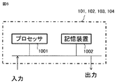
- FIG. 3 is an explanatory diagram showing a partial hardware configuration in a power generation control device for an automotive alternator according to Embodiments 1 to 4.
- FIG. 1 is a configuration diagram illustrating a power generation control device for a vehicle AC generator according to the first embodiment.
- an AC generator 10 for a vehicle mounted on a vehicle such as an automobile includes an armature coil 13 provided on a stator and a field coil 12 provided on a rotor.
- a main body 100, a rectifier 14 for rectifying a three-phase AC voltage output from the armature coil 13 into a DC voltage, and a power generation control device 11 for a vehicle AC generator according to the first embodiment are provided.
- the power generation control device 11 includes a freewheeling diode 16 connected in parallel to the field coil 12, a transistor 15 as a switching element, a voltage control circuit 101, a low voltage protection circuit 102, and a low voltage protection continuous operation prevention circuit 103. And.
- the voltage control circuit 101, the low voltage protection circuit 102, and the low voltage protection continuous operation prevention circuit 103 are configured to operate by being supplied with electric power from an internal power supply (not shown) provided in the power generation control device 11. ing.
- the voltage control circuit 101, the low voltage protection circuit 102, and the low voltage protection continuous operation prevention circuit 103 include a processor 1001 and a storage device 1002, as shown in FIG.
- the storage device includes a volatile storage device such as a random access memory and a nonvolatile auxiliary storage device such as a flash memory. Further, an auxiliary storage device of a hard disk may be provided instead of the flash memory.
- the processor 1001 executes a program input from the storage device 1002. In this case, a program is input from the auxiliary storage device to the processor 1001 via the volatile storage device. Further, the processor 1001 may output data such as a calculation result to the volatile storage device of the storage device 1002, or may store the data in the auxiliary storage device via the volatile storage device.
- the transistor 15 is connected in series to a parallel connection body of the reflux diode 16 and the field coil 12.
- the voltage control circuit 101 controls the excitation current flowing through the field coil 12 by switching the transistor 15 so that the generated voltage generated by the AC generator main body 100 becomes the target set voltage.
- the generated voltage as a three-phase AC voltage induced in the armature coil 13 of the AC generator main body 100 is full-wave rectified by the rectifier 14 to be converted into a DC voltage, and supplied to the battery 17 mounted on the vehicle.
- the battery voltage as the terminal voltage of the battery 17 is the same as or proportional to the generated voltage of the AC generator body 100.
- the low voltage protection circuit 102 When the low voltage protection circuit 102 detects that the power generation voltage of the AC generator main body 100 is smaller than a predetermined voltage set in advance, the low voltage protection circuit 102 controls the transistor 15 regardless of the switching control of the transistor 15 by the voltage control circuit 101. It is turned on in a predetermined routine to be described later, and the generated current of the AC generator body 100 is increased by forcibly increasing the exciting current flowing in the field coil 12.
- the generated voltage of the AC generator body 100 may be directly detected to detect that the generated voltage is smaller than a predetermined voltage.
- the low voltage protection continuous operation prevention circuit 103 stops the above-described operation of the low voltage protection circuit 102 when the operation of the low voltage protection circuit 102 continues for a predetermined time.
- the power generation control device 11 hoods back the excitation current flowing through the field coil 12 so that the generated voltage of the AC generator body 100 matches the target set voltage given from the outside.
- the voltage control circuit 101 generates a drive signal having a duty ratio corresponding to a deviation between a target set voltage given from the outside and the generated voltage of the AC generator main body 100, and applies this drive signal to the gate of the transistor 15.
- the transistor 15 is controlled by PWM (Pulse Width Modulation).
- the low voltage protection circuit 102 detects that the power generation voltage of the AC generator main body 100 has dropped below a predetermined voltage VBL set in advance, and turns off the transistor 15 regardless of the switching control of the transistor 15 by the voltage control circuit 101. It is turned on, and the operation of increasing the generated voltage of the AC generator main body 100 by increasing the excitation current is performed.
- the operation of the low voltage protection circuit 102 is stopped and the transistor 15 is controlled by the voltage control circuit 101 as usual.
- the low voltage protection circuit 102 operates as described above to increase the power generation voltage of the AC generator main body 100.
- the battery voltage is set in advance by the failure of a circuit that detects the battery voltage.
- the power generation voltage of the AC generator main body 100 may increase unintentionally and may enter an overvoltage state.
- the low voltage protection continuous operation prevention circuit 103 continuously continues for a predetermined time TVBL when the low voltage protection circuit 102 is set in advance. It is detected that the above-described operation for increasing the power generation voltage of the AC generator main body 100 is continued, and the operation of the low voltage protection circuit 102 is stopped.
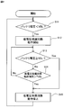
- FIG. 2 is a flowchart for explaining the operation of the power generation control device for the automotive alternator according to the first embodiment.
- the operation of the power generation control device for the vehicle alternator shown in the flowchart of FIG. 2 is repeated at a predetermined cycle.
- the low voltage protection circuit 102 compares the battery voltage as the output voltage of the battery 17 with a predetermined voltage VBL set in advance, and the battery voltage is compared with the predetermined voltage VBL. If it determines with it being small (Yes), it will progress to the following step S12.
- step S12 the low-voltage protection circuit 102 starts operating, and regardless of the switching control of the transistor 15 by the voltage control circuit 101, the transistor 15 is turned on to increase the excitation current to generate power from the AC generator body 100. Start the operation to increase the voltage.
- step S13 the low voltage protection circuit 102 compares the battery voltage with a predetermined voltage VBL set in advance, and determines that the battery voltage is equal to or higher than the predetermined voltage VBL (Yes).
- step S15 the low voltage protection circuit 102 stops the above-described operation.
- the process proceeds to step S14.
- step S14 the low voltage protection continuous operation prevention circuit 103 compares the operation time of the low voltage protection circuit 102 with a predetermined time TVBL, and the operation time of the low voltage protection circuit 102 is a predetermined time. If it determines with not exceeding TVBL (No), it will return to step S13. On the other hand, if it is determined in step S14 that the operation time of the low voltage protection circuit 102 has exceeded the predetermined time TVBL (Yes), the process proceeds to step S15, where the low voltage protection continuous operation prevention circuit 103 has a low voltage. The aforementioned operation of the protection circuit 102 is stopped. As a result, the power generation control device 11 returns to normal operation by the voltage control circuit 101.
- the low voltage protection circuit 102 continuously generates the generated voltage of the alternator main body 100 over a predetermined time.
- the low voltage protection continuous operation prevention circuit 103 is configured to detect it and stop the operation of the low voltage protection circuit 102. It becomes possible to prevent the generated voltage of the AC generator main body 100 from entering an overvoltage state.
- the low voltage protection continuous operation prevention circuit 103 measures the time of the low voltage state of the battery voltage instead of the operation time of the low voltage protection circuit 102, and determines the predetermined time when the low voltage state of the battery voltage is set in advance. It may be configured to stop the operation of the low voltage protection circuit 102 when it is detected that the operation has continued beyond the limit.
- FIG. 3 is a configuration diagram illustrating a power generation control device for an automotive alternator according to the second embodiment.
- a power generation control device 11 includes a freewheeling diode 16 connected in parallel to a field coil 12, a transistor 15 as a switching element, and a power-on-reset circuit (power-on-) as a reset circuit.
- reset-circuit) 104 voltage control circuit 101, low voltage protection circuit 102, and low voltage protection continuous operation prevention circuit 103.
- the power-on reset circuit 104 includes a processor 1001 and a storage device 1002, as shown in FIG.
- the power-on-reset circuit 104 detects the rise and fall of the voltage of the internal power supply (not shown) of the power generation control device 11 and outputs a reset signal.
- the low voltage protection circuit 102 and the low voltage protection continuous operation prevention circuit 103 are reset and validated by a reset signal from the power-on reset circuit 104 when the rising of the voltage of the internal power supply is detected.
- the low voltage protection continuous operation prevention circuit 103 detects that the operation time of the low voltage protection circuit 102 has continued beyond a predetermined time set in advance, the low voltage protection continuous operation prevention circuit 103 performs low voltage protection. While the operation of the circuit 102 is stopped, the low voltage protection circuit 102 and the low voltage protection continuous operation prevention circuit 103 are invalidated. Therefore, after the low voltage protection circuit 102 and the low voltage protection continuous operation prevention circuit 103 are invalidated, the power generation voltage of the AC generator body 100, that is, the battery voltage, is again set to a state below a predetermined voltage. Even then, the low voltage protection circuit 102 does not operate.
- the low voltage protection circuit 102 and the low voltage protection continuous operation prevention circuit 103 are activated when the power-on reset circuit 104 detects the rising of the voltage of the internal power supply. Accordingly, the battery voltage, and hence the generated voltage of the AC generator main body 100, drops below a predetermined voltage set in advance, and the low voltage protection circuit 102 starts the above-described operation, and at the same time, the low voltage protection continuous operation prevention circuit 103 Measures the operating time of the low voltage protection circuit 102.
- the low-voltage protection continuous operation prevention circuit 103 detects that the operation time of the low-voltage protection circuit has continued beyond a predetermined time set in advance, the low-voltage protection circuit 102 and the low-voltage protection continuous operation prevention circuit 103 Is invalidated and the normal operation by the voltage control circuit 101 is started. At this time, since the low voltage protection circuit 102 is invalidated, as described above, even when the battery voltage becomes lower than the predetermined voltage VBL set in advance, the low voltage protection circuit 102 does not operate. Absent.
- the power-on reset circuit 104 also outputs a reset signal when it detects the falling of the internal power supply of the power generation control device 11. Therefore, when the internal power supply is turned off for some reason, the low voltage protection circuit 102 and the low voltage protection continuous operation prevention circuit 103 are reset by a reset signal from the power on reset circuit 104.
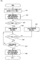
- FIG. 4 is a flowchart showing the operation of the power generation control device for the vehicle alternator according to the second embodiment.
- the power-on / reset circuit 104 detects the rise of the voltage of the internal power supply of the power generation control device 11 and outputs a reset signal.
- the low voltage protection circuit 102 and the low voltage protection continuous operation prevention circuit 103 are validated upon receiving a reset signal from the power-on reset circuit 104.
- step S23 the low voltage protection circuit 102 compares the battery voltage as the output voltage of the battery 17 with a predetermined voltage VBL set in advance, and determines that the battery voltage is smaller than the predetermined voltage VBL. If yes (Yes), the process proceeds to the next step S24.
- step S24 the low-voltage protection circuit 102 starts operation, and regardless of the switching control of the transistor 15 by the voltage control circuit 101, the transistor 15 is turned on and the excitation current is increased to increase the generated voltage of the AC generator body 100. Start to move up.
- step S24 the low voltage protection circuit 102 compares the battery voltage with a predetermined voltage VBL set in advance, and determines that the battery voltage is equal to or higher than the predetermined voltage VBL (Yes). Proceeding to step S25, the low-voltage protection circuit 102 stops the above-described operation and returns to step S23. On the other hand, if it is determined in step S24 that the battery voltage is not equal to or higher than the predetermined voltage VBL (No), the process proceeds to step S27.
- step S27 the low voltage protection continuous operation prevention circuit 103 compares the operation time of the low voltage protection circuit 102 with a predetermined time TVBL, and the operation time of the low voltage protection circuit 102 is a predetermined time. If it is determined that the TVBL is not exceeded (No), the process returns to step S26. On the other hand, if it is determined in step S27 that the operation time of the low voltage protection circuit 102 exceeds the predetermined time TVBL (Yes), the process proceeds to step S28, where the low voltage protection continuous operation prevention circuit 103 and the low voltage protection circuit 103 The protection circuit 102 is disabled, and the above-described operation of the low voltage protection circuit 102 is stopped. In this way, the low voltage protection circuit 102 is disabled and its operation stops, so that the power generation control device 11 returns to normal operation by the voltage control circuit 101.
- the low voltage protection circuit 102 since the low voltage protection circuit 102 is invalidated in step S28, the low voltage protection circuit 102 does not operate even when the battery voltage becomes lower than the predetermined voltage VBL set in advance again. Absent.
- the power generation voltage of the AC generator main body 100 may be directly detected to detect that the power generation voltage is smaller than a predetermined voltage.
- the low voltage protection continuous operation prevention circuit 103 once the low voltage protection continuous operation prevention circuit 103 operates, the low voltage protection circuit 102 and the low voltage protection continuous operation prevention circuit 103 are invalidated. This is because when the low-voltage protection continuous operation prevention circuit 103 operates, there is a high possibility that it is in some abnormal state such as a failure of the circuit that detects the battery voltage. This is because it is not preferable to operate the low voltage protection circuit 102 to be increased.
- the low voltage protection circuit 102 If the battery voltage, and thus the generated voltage of the AC generator main body 100 does not rise beyond the predetermined voltage even if the low voltage protection circuit 102 operates for a predetermined time TVBL, the low voltage protection circuit is disabled. In addition, a safe power generation control device can be obtained.
- the low voltage protection circuit 102 and the low voltage protection continuous operation prevention circuit 103 are Since it is invalidated, for example, in the case of some abnormal state such as a failure of a circuit that detects the battery voltage, the low voltage protection circuit 102 does not operate, and the generated voltage is not increased forcibly.
- the control device 11 can be operated safely.
- the low voltage protection continuous operation prevention circuit 103 measures the time of the low voltage state of the battery voltage instead of the operation time of the low voltage protection circuit 102, and determines the predetermined time when the low voltage state of the battery voltage is set in advance. It may be configured to stop the operation of the low voltage protection circuit 102 when it is detected that the operation has continued beyond the limit.
- FIG. 5 is a configuration diagram illustrating a power generation control device for an automotive alternator according to the third embodiment.
- the power generation control device for an automotive alternator according to Embodiment 3 is characterized in that the voltage control circuit 101 is provided outside the power generation control device 11, for example, an ECU (Engine Control Unit).
- ECU Engine Control Unit
- Other configurations are the same as those of the generator control device for the AC generator according to the second embodiment.
- the alternator power generation control device by performing power generation control on the ECU side, it becomes possible to utilize information such as the state of the engine and the vehicle for power generation control. It is possible to provide comfortable vehicle travel by finely controlling the driving of the load.
- the power generation control device of the generator that can raise the voltage of the AC generator main body by the constant voltage protection circuit and the low voltage protection continuous operation prevention circuit, and can perform a safe and stable operation. Can be obtained.
- the power generation control device for the vehicle alternator according to the fourth embodiment is the above-described predetermined voltage set in advance in the power generation control device for the vehicle alternator according to the first to third embodiments.
- the VBL and the predetermined time TVBL set in advance can be set by an external control device provided outside the power generation control device 11.
- the other configurations are the power generation control device for the vehicle alternator according to the first embodiment, the power generation control device for the vehicle alternator according to the second embodiment, or the power generation control of the vehicle alternator according to the third embodiment. It is the same as the device.
- the external control device that can set the predetermined voltage VBL set in advance and the predetermined time TVBL set in advance may be, for example, the above-described ECU, or other control device. Of course there may be.
- the predetermined voltage VBL and the predetermined time TVBL can be set by the external control device provided outside the power generation control device. Even when the target setting voltage of the generator voltage of the alternator main body 100 is changed, the generated voltage of the alternator main body 100 can be changed without changing the low voltage protection circuit 102 and the low voltage protection continuous operation prevention circuit 103.
- the predetermined voltage VBL and the predetermined time TVBL can be easily set corresponding to the target setting voltage.
- the power generation control device for an AC generator of the present application can be used in the field of an AC generator mounted on a vehicle such as an automobile, and eventually in the field of a vehicle such as an automobile.
Abstract
L'invention concerne un dispositif de commande de génération d'énergie conçu de façon à empêcher une élévation de tension involontaire par un circuit de protection basse tension par arrêt ou désactivation du fonctionnement du circuit de protection basse tension lorsqu'un état dans lequel la tension générée d'un générateur de CA de véhicule est inférieure ou égale à une tension prédéterminée prédéfinie continue jusqu'à ce qu'un temps prédéterminé prédéfini ou plus soit écoulé.
Priority Applications (5)
| Application Number | Priority Date | Filing Date | Title |
|---|---|---|---|
| CN201880093259.1A CN112106290A (zh) | 2018-05-15 | 2018-05-15 | 车辆用交流发电机的发电控制装置 |
| PCT/JP2018/018700 WO2019220526A1 (fr) | 2018-05-15 | 2018-05-15 | Dispositif de commande de génération d'énergie pour un générateur de ca de véhicule |
| US16/970,012 US11342870B2 (en) | 2018-05-15 | 2018-05-15 | Power generation controller for vehicle AC power generator |
| JP2020518845A JP7058731B2 (ja) | 2018-05-15 | 2018-05-15 | 車両用交流発電機の発電制御装置 |
| EP18918760.2A EP3796545A4 (fr) | 2018-05-15 | 2018-05-15 | Dispositif de commande de génération d'énergie pour un générateur de ca de véhicule |
Applications Claiming Priority (1)
| Application Number | Priority Date | Filing Date | Title |
|---|---|---|---|
| PCT/JP2018/018700 WO2019220526A1 (fr) | 2018-05-15 | 2018-05-15 | Dispositif de commande de génération d'énergie pour un générateur de ca de véhicule |
Publications (1)
| Publication Number | Publication Date |
|---|---|
| WO2019220526A1 true WO2019220526A1 (fr) | 2019-11-21 |
Family
ID=68540047
Family Applications (1)
| Application Number | Title | Priority Date | Filing Date |
|---|---|---|---|
| PCT/JP2018/018700 WO2019220526A1 (fr) | 2018-05-15 | 2018-05-15 | Dispositif de commande de génération d'énergie pour un générateur de ca de véhicule |
Country Status (5)
| Country | Link |
|---|---|
| US (1) | US11342870B2 (fr) |
| EP (1) | EP3796545A4 (fr) |
| JP (1) | JP7058731B2 (fr) |
| CN (1) | CN112106290A (fr) |
| WO (1) | WO2019220526A1 (fr) |
Citations (4)
| Publication number | Priority date | Publication date | Assignee | Title |
|---|---|---|---|---|
| JPH05336682A (ja) * | 1992-05-28 | 1993-12-17 | Suzuki Motor Corp | 車両用発電機制御装置 |
| JP3283325B2 (ja) | 1993-03-31 | 2002-05-20 | 富士通テン株式会社 | オルタネータ制御装置 |
| JP2006246574A (ja) * | 2005-03-01 | 2006-09-14 | Denso Corp | 発電制御装置 |
| JP2015065788A (ja) * | 2013-09-26 | 2015-04-09 | 株式会社デンソー | 車両用回転電機 |
Family Cites Families (3)
| Publication number | Priority date | Publication date | Assignee | Title |
|---|---|---|---|---|
| JP3991983B2 (ja) | 2003-12-19 | 2007-10-17 | 日産自動車株式会社 | 車両の駆動制御装置 |
| JP4682901B2 (ja) | 2006-04-04 | 2011-05-11 | 株式会社デンソー | 発電制御システム |
| JP4450085B2 (ja) * | 2008-03-17 | 2010-04-14 | 株式会社デンソー | 車両用発電制御装置 |
-
2018
- 2018-05-15 WO PCT/JP2018/018700 patent/WO2019220526A1/fr unknown
- 2018-05-15 US US16/970,012 patent/US11342870B2/en active Active
- 2018-05-15 CN CN201880093259.1A patent/CN112106290A/zh not_active Withdrawn
- 2018-05-15 JP JP2020518845A patent/JP7058731B2/ja active Active
- 2018-05-15 EP EP18918760.2A patent/EP3796545A4/fr not_active Withdrawn
Patent Citations (5)
| Publication number | Priority date | Publication date | Assignee | Title |
|---|---|---|---|---|
| JPH05336682A (ja) * | 1992-05-28 | 1993-12-17 | Suzuki Motor Corp | 車両用発電機制御装置 |
| JP3283325B2 (ja) | 1993-03-31 | 2002-05-20 | 富士通テン株式会社 | オルタネータ制御装置 |
| JP2006246574A (ja) * | 2005-03-01 | 2006-09-14 | Denso Corp | 発電制御装置 |
| JP4179296B2 (ja) | 2005-03-01 | 2008-11-12 | 株式会社デンソー | 発電制御装置 |
| JP2015065788A (ja) * | 2013-09-26 | 2015-04-09 | 株式会社デンソー | 車両用回転電機 |
Non-Patent Citations (1)
| Title |
|---|
| See also references of EP3796545A4 |
Also Published As
| Publication number | Publication date |
|---|---|
| US20210104962A1 (en) | 2021-04-08 |
| US11342870B2 (en) | 2022-05-24 |
| EP3796545A1 (fr) | 2021-03-24 |
| JP7058731B2 (ja) | 2022-04-22 |
| EP3796545A4 (fr) | 2021-04-07 |
| CN112106290A (zh) | 2020-12-18 |
| JPWO2019220526A1 (ja) | 2021-02-12 |
Similar Documents
| Publication | Publication Date | Title |
|---|---|---|
| US6734653B2 (en) | Voltage regulator for alternator and method of controlling power generation of alternator | |
| JP2006271136A (ja) | Dc−dcコンバータ装置 | |
| JP2006238611A (ja) | 発電装置および電動機制御装置 | |
| JP5181666B2 (ja) | 界磁巻線型モータおよび界磁巻線型発電機の制御回路 | |
| JP6308092B2 (ja) | 電子制御装置 | |
| JP5452654B2 (ja) | 車両用交流発電機の制御装置 | |
| US20140306521A1 (en) | Method for operating a multi-voltage electrical system of a motor vehicle, a multi-voltage electrical system and means for implementing the method | |
| JP4143648B2 (ja) | 界磁巻線式交流回転電機装置 | |
| JP3997969B2 (ja) | 発電制御装置 | |
| JP6232133B2 (ja) | 電子制御装置 | |
| JP4548469B2 (ja) | 車両用発電制御装置 | |
| JP2009142089A (ja) | 車両用電源装置 | |
| JP2010083420A (ja) | 車両用補機の電源システム | |
| CN113892159A (zh) | 转换器装置及工业用机械 | |
| WO2019220526A1 (fr) | Dispositif de commande de génération d'énergie pour un générateur de ca de véhicule | |
| JP4780171B2 (ja) | 車両用発電制御装置 | |
| KR20150116843A (ko) | 차상 전력 시스템을 위한 에너지 공급 유닛을 작동시키기 위한 방법 | |
| JP6162445B2 (ja) | 電力変換装置 | |
| KR102320892B1 (ko) | 컨버터 시스템의 과전류 방지 장치 및 방법 | |
| JP7198169B2 (ja) | スイッチング電源装置 | |
| JP2009118657A (ja) | 電源装置及びこれを備えた電子機器 | |
| JPH09294392A (ja) | ブラシレスモータの駆動システム | |
| JP4046108B2 (ja) | 発電制御装置 | |
| JP2011167002A (ja) | 電力制御装置 | |
| JP2018125915A (ja) | 車両搭載のインバータの制御方法および制御装置 |
Legal Events
| Date | Code | Title | Description |
|---|---|---|---|
| 121 | Ep: the epo has been informed by wipo that ep was designated in this application |
Ref document number: 18918760 Country of ref document: EP Kind code of ref document: A1 |
|
| ENP | Entry into the national phase |
Ref document number: 2020518845 Country of ref document: JP Kind code of ref document: A |
|
| NENP | Non-entry into the national phase |
Ref country code: DE |
|
| ENP | Entry into the national phase |
Ref document number: 2018918760 Country of ref document: EP Effective date: 20201215 |