WO2019220526A1 - Power generation control device for vehicle ac generator - Google Patents
Power generation control device for vehicle ac generator Download PDFInfo
- Publication number
- WO2019220526A1 WO2019220526A1 PCT/JP2018/018700 JP2018018700W WO2019220526A1 WO 2019220526 A1 WO2019220526 A1 WO 2019220526A1 JP 2018018700 W JP2018018700 W JP 2018018700W WO 2019220526 A1 WO2019220526 A1 WO 2019220526A1
- Authority
- WO
- WIPO (PCT)
- Prior art keywords
- voltage
- circuit
- power generation
- control device
- voltage protection
- Prior art date
Links
Images


Classifications
-
- H—ELECTRICITY
- H02—GENERATION; CONVERSION OR DISTRIBUTION OF ELECTRIC POWER
- H02P—CONTROL OR REGULATION OF ELECTRIC MOTORS, ELECTRIC GENERATORS OR DYNAMO-ELECTRIC CONVERTERS; CONTROLLING TRANSFORMERS, REACTORS OR CHOKE COILS
- H02P9/00—Arrangements for controlling electric generators for the purpose of obtaining a desired output
- H02P9/48—Arrangements for obtaining a constant output value at varying speed of the generator, e.g. on vehicle
-
- H—ELECTRICITY
- H02—GENERATION; CONVERSION OR DISTRIBUTION OF ELECTRIC POWER
- H02P—CONTROL OR REGULATION OF ELECTRIC MOTORS, ELECTRIC GENERATORS OR DYNAMO-ELECTRIC CONVERTERS; CONTROLLING TRANSFORMERS, REACTORS OR CHOKE COILS
- H02P9/00—Arrangements for controlling electric generators for the purpose of obtaining a desired output
- H02P9/006—Means for protecting the generator by using control
-
- H—ELECTRICITY
- H02—GENERATION; CONVERSION OR DISTRIBUTION OF ELECTRIC POWER
- H02P—CONTROL OR REGULATION OF ELECTRIC MOTORS, ELECTRIC GENERATORS OR DYNAMO-ELECTRIC CONVERTERS; CONTROLLING TRANSFORMERS, REACTORS OR CHOKE COILS
- H02P9/00—Arrangements for controlling electric generators for the purpose of obtaining a desired output
- H02P9/02—Details
-
- H—ELECTRICITY
- H02—GENERATION; CONVERSION OR DISTRIBUTION OF ELECTRIC POWER
- H02P—CONTROL OR REGULATION OF ELECTRIC MOTORS, ELECTRIC GENERATORS OR DYNAMO-ELECTRIC CONVERTERS; CONTROLLING TRANSFORMERS, REACTORS OR CHOKE COILS
- H02P9/00—Arrangements for controlling electric generators for the purpose of obtaining a desired output
- H02P9/14—Arrangements for controlling electric generators for the purpose of obtaining a desired output by variation of field
- H02P9/26—Arrangements for controlling electric generators for the purpose of obtaining a desired output by variation of field using discharge tubes or semiconductor devices
- H02P9/30—Arrangements for controlling electric generators for the purpose of obtaining a desired output by variation of field using discharge tubes or semiconductor devices using semiconductor devices
Landscapes
- Engineering & Computer Science (AREA)
- Power Engineering (AREA)
- Control Of Eletrric Generators (AREA)
- Control Of Charge By Means Of Generators (AREA)
Abstract
This power generation control device is configured so as to prevent unintended voltage rise by a low voltage protection circuit by stopping or disabling the operation of the low voltage protection circuit when a state in which the generated voltage of a vehicle AC generator is less than or equal to a preset predetermined voltage continues until a preset predetermined time or longer has elapsed.
Description
本願は、自動車等の車両に搭載される車両用交流発電機の発電制御装置に関するものである。
This application relates to a power generation control device for a vehicle AC generator mounted on a vehicle such as an automobile.
周知のように、自動車等の車両に搭載される車両用交流発電機の発電制御装置は、例えば、発電機の出力端子、又はバッテリ電圧を監視し、目標設定電圧となるよう界磁コイルに供給する励磁電流を調整する回路を備えた半導体集積回路により構成される。車両用交流発電機の発電制御装置は、交流発電機本体の発電電圧が、所定の電圧より高くなる過電圧の状態になると、車両用交流発電機が故障し、車両が走行不能となる可能性がある。特に、過電圧状態は、場合によっては発火の原因となるため、この状態を回避することが優先的に求められる。
As is well known, a power generation control device for a vehicle AC generator mounted on a vehicle such as an automobile monitors, for example, an output terminal of the generator or a battery voltage, and supplies the target coil with a field setting voltage. It is constituted by a semiconductor integrated circuit provided with a circuit for adjusting the exciting current. When the power generation voltage of the AC generator main body is in an overvoltage state where the AC generator main body is higher than a predetermined voltage, the vehicle AC generator may break down and the vehicle may become unable to run. is there. In particular, since an overvoltage state may cause ignition in some cases, it is preferentially required to avoid this state.
一方で、車両用交流発電機の発電電圧が、所定の電圧より低くなる低電圧の状態にあると、バッテリ電圧を電源として動作する電気機器が動作しなくなり、車両の走行不能など意図しない動作が発生する可能性がある。
On the other hand, if the power generation voltage of the vehicle alternator is in a low voltage state that is lower than a predetermined voltage, an electrical device that operates using the battery voltage as a power source will not operate, and an unintended operation such as the inability to travel the vehicle will occur. May occur.
また、車両用交流発電機の発電制御装置に於ける発電電圧を制御するための電圧制御部には、監視する交流発電機本体の出力端子に発生するリップルを除去するためのフィルタが実装されている。そのフィルタは、高周波のリップルを除去するローパスフィルタにより構成される。しかしながら、電圧制御部にローパスフィルタが設けられているため、電圧制御部による発電制御では出力端子若しくはバッテリ電圧の瞬間的な電圧低下に対応することができない。
In addition, a filter for removing ripples generated at the output terminal of the AC generator main body to be monitored is mounted on the voltage control unit for controlling the generated voltage in the generator control device of the vehicle AC generator. Yes. The filter is composed of a low-pass filter that removes high-frequency ripple. However, since the voltage control unit is provided with a low-pass filter, power generation control by the voltage control unit cannot cope with an instantaneous voltage drop of the output terminal or the battery voltage.
更に、バッテリの劣化状態、及び車両用交流発電機の運転中に於けるバッテリがオープン状態になると、前述のローパスフィルタの存在により発電制御装置荷よる発電制御の応答性が遅いので、交流発電機本体の発電電圧のアンダーシュートが発生し、車両用交流発電機に接続された電気機器の電源電圧も低下する可能性がある。
Furthermore, when the battery is in an open state while the battery is in a deteriorated state or during operation of the vehicle alternator, the response of power generation control by the power generation control device is slow due to the presence of the low-pass filter described above. There is a possibility that an undershoot of the power generation voltage of the main body occurs, and the power supply voltage of the electrical equipment connected to the vehicle AC generator is also lowered.
従来、バッテリ端子電圧が異常に低下していない場合は、電圧調整装置で決定される交流発電機本体の発電電圧を制御する通常のデューティ比に代えて、エンジンの回転数に大きな変動を与えない許容最大発電量を与える許容最大デューティ比により交流発電機本体の発電量を制御する技術が提案されている(例えば、特許文献2参照)。
Conventionally, when the battery terminal voltage is not abnormally lowered, the engine speed is not greatly changed in place of the normal duty ratio for controlling the power generation voltage of the AC generator body determined by the voltage regulator. A technique for controlling the power generation amount of the AC generator main body by an allowable maximum duty ratio that gives an allowable maximum power generation amount has been proposed (see, for example, Patent Document 2).
また、従来、交流発電機の発電電圧が、予め設定された所定の電圧以下に低下した場合に、発電制御装置が強制的に界磁コイルに励磁電流を供給するよう動作し、発電電圧を上昇させる低電圧保護回路を設けることが提案されている(例えば、特許文献1参照)。
Conventionally, when the power generation voltage of the AC generator drops below a predetermined voltage set in advance, the power generation control device operates to forcibly supply the exciting current to the field coil, thereby increasing the power generation voltage. It has been proposed to provide a low voltage protection circuit that can be used (see, for example, Patent Document 1).
前述の特許文献1に開示された従来の装置の場合、低電圧保護回路は、交流発電機本体の発電電圧が所定の電圧より低下した低電圧状態になったときに、発電電圧を調整する機能とは関係なく、強制的に界磁コイルに励磁電流を供給して発電電圧を上昇させるように構成されている。従って、低電圧保護機能を持つ発電制御装置に於いて、発電制御装置の故障等により低電圧状態を誤検知した場合に、意図せず交流発電機本体の発電電圧が上昇して過電圧状態となるという課題があった。
In the case of the conventional device disclosed in the above-mentioned Patent Document 1, the low voltage protection circuit has a function of adjusting the generated voltage when the generated voltage of the AC generator main body is in a low voltage state lower than a predetermined voltage. Regardless of, the forcible current is forcibly supplied to the field coil to raise the generated voltage. Therefore, in a power generation control device having a low voltage protection function, when a low voltage state is erroneously detected due to a failure of the power generation control device or the like, the power generation voltage of the AC generator body unintentionally rises to an overvoltage state. There was a problem.
本願は、前述のような課題を解決するためになされたものであり、発電制御装置の故障等により低電圧状態を誤検知した場合に於いても、意図せず交流発電機本体の発電電圧が上昇して過電圧状態となることがなく、安全性に優れた車両用交流発電機の発電制御装置を得ることを目的とする。
The present application was made to solve the above-described problems. Even when a low voltage state is erroneously detected due to a failure of the power generation control device or the like, the generated voltage of the AC generator main body is not intended. An object of the present invention is to obtain a power generation control device for an automotive alternator that does not rise to an overvoltage state and is excellent in safety.
本願に開示される車両用交流発電機の発電制御装置は、
車両に搭載される交流発電機本体の界磁コイルに流れる励磁電流を制御し、前記交流発電機本体の発電電圧を制御するように構成された電圧制御回路と、
前記発電電圧若しくは前記発電電圧に基づく電圧が所定の電圧よりも低下したとき、前記電圧制御回路による前記発電電圧の制御とは無関係に、前記励磁電流を増大させて前記発電電圧を上昇させるように動作する低電圧保護回路と、
前記低電圧保護回路の前記動作が所定時間を超えて継続したとき、前記低電圧保護回路の前記動作を停止させるように動作する低電圧保護連続動作防止回路と、
を備えたことを特徴とする。 The power generation control device for a vehicle alternator disclosed in the present application is:
A voltage control circuit configured to control an exciting current flowing in a field coil of an AC generator body mounted on a vehicle, and to control a generated voltage of the AC generator body;
When the generated voltage or a voltage based on the generated voltage is lower than a predetermined voltage, the excitation current is increased to increase the generated voltage regardless of the control of the generated voltage by the voltage control circuit. An operating low voltage protection circuit;
A low-voltage protection continuous operation prevention circuit that operates to stop the operation of the low-voltage protection circuit when the operation of the low-voltage protection circuit continues beyond a predetermined time;
It is provided with.
本願に開示される車両用交流発電機の発電制御装置によれば、前記発電電圧若しくは前記発電電圧に基づく電圧が所定の電圧よりも低下したとき、前記電圧制御回路による前記発電電圧の制御とは無関係に、前記励磁電流を増大させて前記発電電圧を上昇させるように動作する低電圧保護回路と、前記低電圧保護回路の前記動作が所定時間を超えて継続したとき、前記低電圧保護回路の前記動作を停止させるように動作する低電圧保護連続動作防止回路とを備えているので、発電制御装置の故障等により低電圧を誤検知した場合においても、意図せず発電電圧が上昇して過電圧状態になることがなく、安全性に優れた車両用交流発電機の発電制御装置を得ることができる。
According to the power generation control device for an AC generator for a vehicle disclosed in the present application, when the generated voltage or a voltage based on the generated voltage is lower than a predetermined voltage, the control of the generated voltage by the voltage control circuit is Irrespective of the low voltage protection circuit that operates to increase the excitation current and increase the generated voltage, and when the operation of the low voltage protection circuit continues beyond a predetermined time, Since it has a low voltage protection continuous operation prevention circuit that operates to stop the operation, even if a low voltage is erroneously detected due to a failure of the power generation control device, etc., the generated voltage rises unintentionally and overvoltage It is possible to obtain a power generation control device for an automotive alternator that is not in a state and is excellent in safety.
実施の形態1.
図1は、実施の形態1による車両用交流発電機の発電制御装置を示す構成図である。図1に於いて、自動車等の車両に搭載される車両用交流発電機10は、固定子に設けられた電機子コイル13と回転子に設けられた界磁コイル12とを備えた交流発電機本体100と、電機子コイル13が出力する三相交流電圧を直流電圧に整流する整流器14と、実施の形態1による車両用交流発電機の発電制御装置11を備えている。 Embodiment 1 FIG.
FIG. 1 is a configuration diagram illustrating a power generation control device for a vehicle AC generator according to the first embodiment. In FIG. 1, anAC generator 10 for a vehicle mounted on a vehicle such as an automobile includes an armature coil 13 provided on a stator and a field coil 12 provided on a rotor. A main body 100, a rectifier 14 for rectifying a three-phase AC voltage output from the armature coil 13 into a DC voltage, and a power generation control device 11 for a vehicle AC generator according to the first embodiment are provided.
図1は、実施の形態1による車両用交流発電機の発電制御装置を示す構成図である。図1に於いて、自動車等の車両に搭載される車両用交流発電機10は、固定子に設けられた電機子コイル13と回転子に設けられた界磁コイル12とを備えた交流発電機本体100と、電機子コイル13が出力する三相交流電圧を直流電圧に整流する整流器14と、実施の形態1による車両用交流発電機の発電制御装置11を備えている。 Embodiment 1 FIG.
FIG. 1 is a configuration diagram illustrating a power generation control device for a vehicle AC generator according to the first embodiment. In FIG. 1, an
発電制御装置11は、界磁コイル12に並列に接続された還流ダイオード16と、スイッチング素子としてのトランジスタ15と、電圧制御回路101と、低電圧保護回路102と、低電圧保護連続動作防止回路103とを備えている。電圧制御回路101と、低電圧保護回路102と、低電圧保護連続動作防止回路103は、発電制御装置11に設けられた内部電源(図示せず)により電力が供給されて動作するように構成されている。
The power generation control device 11 includes a freewheeling diode 16 connected in parallel to the field coil 12, a transistor 15 as a switching element, a voltage control circuit 101, a low voltage protection circuit 102, and a low voltage protection continuous operation prevention circuit 103. And. The voltage control circuit 101, the low voltage protection circuit 102, and the low voltage protection continuous operation prevention circuit 103 are configured to operate by being supplied with electric power from an internal power supply (not shown) provided in the power generation control device 11. ing.
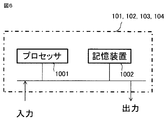
電圧制御回路101と、低電圧保護回路102と、低電圧保護連続動作防止回路103は、ハードウエアの一例を図6に示すように、プロセッサ1001と記憶装置1002から構成される。記憶装置は図示していないが、ランダムアクセスメモリ等の揮発性記憶装置と、フラッシュメモリ等の不揮発性の補助記憶装置とを具備する。また、フラッシュメモリの代わりにハードディスクの補助記憶装置を具備してもよい。プロセッサ1001は、記憶装置1002から入力されたプログラムを実行する。この場合、補助記憶装置から揮発性記憶装置を介してプロセッサ1001にプログラムが入力される。また、プロセッサ1001は、演算結果等のデータを記憶装置1002の揮発性記憶装置に出力してもよいし、揮発性記憶装置を介して補助記憶装置にデータを保存してもよい。
The voltage control circuit 101, the low voltage protection circuit 102, and the low voltage protection continuous operation prevention circuit 103 include a processor 1001 and a storage device 1002, as shown in FIG. Although not shown, the storage device includes a volatile storage device such as a random access memory and a nonvolatile auxiliary storage device such as a flash memory. Further, an auxiliary storage device of a hard disk may be provided instead of the flash memory. The processor 1001 executes a program input from the storage device 1002. In this case, a program is input from the auxiliary storage device to the processor 1001 via the volatile storage device. Further, the processor 1001 may output data such as a calculation result to the volatile storage device of the storage device 1002, or may store the data in the auxiliary storage device via the volatile storage device.
トランジスタ15は、還流ダイオード16と界磁コイル12との並列接続体に直列接続されている。電圧制御回路101は、交流発電機本体100が発電する発電電圧が目標設定電圧になるように、トランジスタ15をスイッチング制御して界磁コイル12に流れる励磁電流を制御する。
The transistor 15 is connected in series to a parallel connection body of the reflux diode 16 and the field coil 12. The voltage control circuit 101 controls the excitation current flowing through the field coil 12 by switching the transistor 15 so that the generated voltage generated by the AC generator main body 100 becomes the target set voltage.
交流発電機本体100の電機子コイル13に誘起された三相交流電圧としての発電電圧は、整流器14により全波整流されて直流電圧に変換され、車両に搭載されたバッテリ17に供給される。バッテリ17の端子電圧としてのバッテリ電圧は、交流発電機本体100の発電電圧と同一若しくは比例関係にある。
The generated voltage as a three-phase AC voltage induced in the armature coil 13 of the AC generator main body 100 is full-wave rectified by the rectifier 14 to be converted into a DC voltage, and supplied to the battery 17 mounted on the vehicle. The battery voltage as the terminal voltage of the battery 17 is the same as or proportional to the generated voltage of the AC generator body 100.
低電圧保護回路102は、交流発電機本体100の発電電圧が予め設定された所定の電圧よりも小さいことを検出したとき、電圧制御回路101によるトランジスタ15のスイッチング制御とは無関係に、トランジスタ15を後述する所定のルーチンでオンとし、強制的に界磁コイル12に流れる励磁電流を増大させて交流発電機本体100の発電電圧を上昇させる。ここでは、交流発電機本体100の発電電圧が予め設定された所定の電圧よりも小さいことを検出する手段として、後述するように、バッテリ電圧が所定の電圧VBLよりも小さいことを検出するようにしているが、交流発電機本体100の発電電圧を直接検出し、その発電電圧が所定の電圧よりも小さいことを検出するようにしてもよい。
When the low voltage protection circuit 102 detects that the power generation voltage of the AC generator main body 100 is smaller than a predetermined voltage set in advance, the low voltage protection circuit 102 controls the transistor 15 regardless of the switching control of the transistor 15 by the voltage control circuit 101. It is turned on in a predetermined routine to be described later, and the generated current of the AC generator body 100 is increased by forcibly increasing the exciting current flowing in the field coil 12. Here, as means for detecting that the generated voltage of the AC generator main body 100 is smaller than a predetermined voltage set in advance, it is detected that the battery voltage is smaller than the predetermined voltage VBL, as will be described later. However, the generated voltage of the AC generator body 100 may be directly detected to detect that the generated voltage is smaller than a predetermined voltage.
低電圧保護連続動作防止回路103は、後述するように、低電圧保護回路102の動作が予め設定された所定の時間を超えて継続したとき、低電圧保護回路102の前述の動作を停止させる。
As described later, the low voltage protection continuous operation prevention circuit 103 stops the above-described operation of the low voltage protection circuit 102 when the operation of the low voltage protection circuit 102 continues for a predetermined time.
車両用交流発電機10の通常動作時には、発電制御装置11は、外部から与えられる目標設定電圧に交流発電機本体100の発電電圧が一致するように、界磁コイル12に流れる励磁電流をフードバック制御する。例えば、電圧制御回路101は、外部から与えられる目標設定電圧と交流発電機本体100の発電電圧との偏差に対応したデューティ比を有する駆動信号を生成し、この駆動信号をトランジスタ15のゲートに与えてトランジスタ15をPWM(Pulse Width Modulation)制御する。
During normal operation of the vehicular AC generator 10, the power generation control device 11 hoods back the excitation current flowing through the field coil 12 so that the generated voltage of the AC generator body 100 matches the target set voltage given from the outside. Control. For example, the voltage control circuit 101 generates a drive signal having a duty ratio corresponding to a deviation between a target set voltage given from the outside and the generated voltage of the AC generator main body 100, and applies this drive signal to the gate of the transistor 15. The transistor 15 is controlled by PWM (Pulse Width Modulation).
トランジスタ15がオンのときは、直流電源としてのバッテリ17から界磁コイル12に励磁電流が流されて交流発電機本体100の発電電圧が上昇し、トランジスタ15がオフのときは、界磁コイル12に流れていた励磁電流は還流ダイオード16を介して還流して減少し、交流発電機本体100の発電電圧は低下する。従って、外部から与えられる目標設定電圧と交流発電機本体100の発電電圧との偏差を「0」とするようにトランジスタ15をPWM制御することで、交流発電機本体100の発電電圧は、外部から与えられる目標設定電圧に一致するように制御される。
When the transistor 15 is on, an exciting current flows from the battery 17 serving as a DC power source to the field coil 12 to increase the generated voltage of the AC generator main body 100. When the transistor 15 is off, the field coil 12 The excitation current that has flowed through the current flows back through the freewheeling diode 16 and decreases, and the generated voltage of the AC generator body 100 decreases. Therefore, by performing PWM control on the transistor 15 so that the deviation between the target set voltage given from the outside and the generated voltage of the AC generator main body 100 is “0”, the generated voltage of the AC generator main body 100 is externally applied. Control is performed so as to match a given target set voltage.
次に、交流発電機本体100の発電電圧が何らかの理由で低下した場合の発電制御装置11の動作について説明する。低電圧保護回路102は、交流発電機本体100の発電電圧が予め設定された所定の電圧VBL未満に低下したことを検知し、電圧制御回路101によるトランジスタ15のスイッチング制御に関係なく、トランジスタ15をオンし、励磁電流を増加させて交流発電機本体100の発電電圧を上昇させる動作を行う。交流発電機本体100の発電電圧が前述の所定の電圧VBL以上に上昇した場合、低電圧保護回路102の動作が停止し、トランジスタ15は通常のように電圧制御回路101により制御される。
Next, the operation of the power generation control device 11 when the power generation voltage of the AC generator main body 100 decreases for some reason will be described. The low voltage protection circuit 102 detects that the power generation voltage of the AC generator main body 100 has dropped below a predetermined voltage VBL set in advance, and turns off the transistor 15 regardless of the switching control of the transistor 15 by the voltage control circuit 101. It is turned on, and the operation of increasing the generated voltage of the AC generator main body 100 by increasing the excitation current is performed. When the generated voltage of the AC generator main body 100 rises above the predetermined voltage VBL, the operation of the low voltage protection circuit 102 is stopped and the transistor 15 is controlled by the voltage control circuit 101 as usual.
低電圧保護回路102は、前述のように動作して交流発電機本体100の発電電圧を上昇させるが、例えば、バッテリ電圧を検知する回路の故障により、バッテリ電圧が予め設定された前述の所定の電圧VBL以上であるにも関わらず、低電圧保護回路102が動作した場合、意図せず交流発電機本体100の発電電圧が上昇し、過電圧状態となる可能性がある。
The low voltage protection circuit 102 operates as described above to increase the power generation voltage of the AC generator main body 100. For example, the battery voltage is set in advance by the failure of a circuit that detects the battery voltage. When the low voltage protection circuit 102 is operated despite the voltage being equal to or higher than the voltage VBL, the power generation voltage of the AC generator main body 100 may increase unintentionally and may enter an overvoltage state.
そこで、交流発電機本体100の発電電圧が過電圧状態となることを避けるため、低電圧保護連続動作防止回路103は、低電圧保護回路102が予め設定された所定の時間TVBLを超えて連続して交流発電機本体100の発電電圧を上昇させる前述の動作を継続したことを検知し、低電圧保護回路102の動作を停止させるように動作する。
Therefore, in order to avoid that the generated voltage of the AC generator main body 100 is in an overvoltage state, the low voltage protection continuous operation prevention circuit 103 continuously continues for a predetermined time TVBL when the low voltage protection circuit 102 is set in advance. It is detected that the above-described operation for increasing the power generation voltage of the AC generator main body 100 is continued, and the operation of the low voltage protection circuit 102 is stopped.
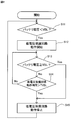
図2は、実施の形態1による車両用交流発電機の発電制御装置の動作を説明するフローチャートである。図2のフローチャートで示す車両用交流発電機の発電制御装置の動作は、所定の周期で繰り返される。図2に於いて、ステップS11に於いて、低電圧保護回路102は、バッテリ17の出力電圧としてのバッテリ電圧と予め設定された所定の電圧VBLとを比較し、バッテリ電圧が所定の電圧VBLより小さいと判定すれば(Yes)、次のステップS12に進む。
FIG. 2 is a flowchart for explaining the operation of the power generation control device for the automotive alternator according to the first embodiment. The operation of the power generation control device for the vehicle alternator shown in the flowchart of FIG. 2 is repeated at a predetermined cycle. In FIG. 2, in step S11, the low voltage protection circuit 102 compares the battery voltage as the output voltage of the battery 17 with a predetermined voltage VBL set in advance, and the battery voltage is compared with the predetermined voltage VBL. If it determines with it being small (Yes), it will progress to the following step S12.
ステップS12に於いて、低電圧保護回路102が動作を開始し、電圧制御回路101によるトランジスタ15のスイッチング制御に関係なく、トランジスタ15をオンし、励磁電流を増加させて交流発電機本体100の発電電圧を上昇させる動作を開始する。
In step S12, the low-voltage protection circuit 102 starts operating, and regardless of the switching control of the transistor 15 by the voltage control circuit 101, the transistor 15 is turned on to increase the excitation current to generate power from the AC generator body 100. Start the operation to increase the voltage.
次に、ステップS13に於いて、低電圧保護回路102は、バッテリ電圧と予め設定された所定の電圧VBLとを比較し、バッテリ電圧が所定の電圧VBL以上であると判定すれば(Yes)、ステップS15に進み、低電圧保護回路102は前述の動作を停止する。一方、ステップS13に於いて、バッテリ電圧が所定の電圧VBL以上でなければ(No)、ステップS14に進む。
Next, in step S13, the low voltage protection circuit 102 compares the battery voltage with a predetermined voltage VBL set in advance, and determines that the battery voltage is equal to or higher than the predetermined voltage VBL (Yes). In step S15, the low voltage protection circuit 102 stops the above-described operation. On the other hand, if the battery voltage is not equal to or higher than the predetermined voltage VBL in step S13 (No), the process proceeds to step S14.
ステップS14に於いて、低電圧保護連続動作防止回路103は、低電圧保護回路102の動作時間と予め定められた所定の時間TVBLとを比較し、低電圧保護回路102の動作時間が所定の時間TVBLを超えていないと判定すれば(No)、ステップS13に戻る。一方、ステップS14に於いて、低電圧保護回路102の動作時間が所定の時間TVBLを超えていると判定すれば(Yes)、ステップS15に進んで、低電圧保護連続動作防止回路103は低電圧保護回路102の前述の動作を停止させる。その結果、発電制御装置11は、電圧制御回路101による通常動作に復帰する。
In step S14, the low voltage protection continuous operation prevention circuit 103 compares the operation time of the low voltage protection circuit 102 with a predetermined time TVBL, and the operation time of the low voltage protection circuit 102 is a predetermined time. If it determines with not exceeding TVBL (No), it will return to step S13. On the other hand, if it is determined in step S14 that the operation time of the low voltage protection circuit 102 has exceeded the predetermined time TVBL (Yes), the process proceeds to step S15, where the low voltage protection continuous operation prevention circuit 103 has a low voltage. The aforementioned operation of the protection circuit 102 is stopped. As a result, the power generation control device 11 returns to normal operation by the voltage control circuit 101.
以上述べたように、実施の形態1による交流発電機の発電制御装置によれば、低電圧保護回路102が予め設定された所定の時間を超えて連続して交流発電機本体100の発電電圧を上昇させる動作を継続したときは、低電圧保護連続動作防止回路103がそれを検出して低電圧保護回路102の動作を停止させるように構成されているので、電圧制御回路101による通常の発電電圧の制御が有効となり、交流発電機本体100の発電電圧が過電圧状態になることを防止することができる。
As described above, according to the generator control device for an alternator according to the first embodiment, the low voltage protection circuit 102 continuously generates the generated voltage of the alternator main body 100 over a predetermined time. When the operation of increasing the voltage is continued, the low voltage protection continuous operation prevention circuit 103 is configured to detect it and stop the operation of the low voltage protection circuit 102. It becomes possible to prevent the generated voltage of the AC generator main body 100 from entering an overvoltage state.
尚、低電圧保護連続動作防止回路103は、低電圧保護回路102の動作時間に代えてバッテリ電圧の低電圧状態の時間を計測し、バッテリ電圧の低電圧状態が予め設定された所定の時間を超えて継続したことを検知しときに、低電圧保護回路102の動作を停止させるように構成されていてもよい。
The low voltage protection continuous operation prevention circuit 103 measures the time of the low voltage state of the battery voltage instead of the operation time of the low voltage protection circuit 102, and determines the predetermined time when the low voltage state of the battery voltage is set in advance. It may be configured to stop the operation of the low voltage protection circuit 102 when it is detected that the operation has continued beyond the limit.
実施の形態2.
次に実施の形態2による車両用交流発電機の発電制御装置について説明する。図3は、実施の形態2による車両用交流発電機の発電制御装置を示す構成図である。図3に於いて、発電制御装置11は、界磁コイル12に並列に接続された還流ダイオード16と、スイッチング素子としてのトランジスタ15と、リセット回路としてのパワー・オン・リセット回路(power-on-reset-circuit)104と、電圧制御回路101と、低電圧保護回路102と、低電圧保護連続動作防止回路103とを備えている。パワー・オン・リセット回路104は、前述のハードウエアの一例を図6に示すように、プロセッサ1001と記憶装置1002から構成される。 Embodiment 2. FIG.
Next, a power generation control device for an automotive alternator according to Embodiment 2 will be described. FIG. 3 is a configuration diagram illustrating a power generation control device for an automotive alternator according to the second embodiment. In FIG. 3, a powergeneration control device 11 includes a freewheeling diode 16 connected in parallel to a field coil 12, a transistor 15 as a switching element, and a power-on-reset circuit (power-on-) as a reset circuit. reset-circuit) 104, voltage control circuit 101, low voltage protection circuit 102, and low voltage protection continuous operation prevention circuit 103. The power-on reset circuit 104 includes a processor 1001 and a storage device 1002, as shown in FIG.
次に実施の形態2による車両用交流発電機の発電制御装置について説明する。図3は、実施の形態2による車両用交流発電機の発電制御装置を示す構成図である。図3に於いて、発電制御装置11は、界磁コイル12に並列に接続された還流ダイオード16と、スイッチング素子としてのトランジスタ15と、リセット回路としてのパワー・オン・リセット回路(power-on-reset-circuit)104と、電圧制御回路101と、低電圧保護回路102と、低電圧保護連続動作防止回路103とを備えている。パワー・オン・リセット回路104は、前述のハードウエアの一例を図6に示すように、プロセッサ1001と記憶装置1002から構成される。 Embodiment 2. FIG.
Next, a power generation control device for an automotive alternator according to Embodiment 2 will be described. FIG. 3 is a configuration diagram illustrating a power generation control device for an automotive alternator according to the second embodiment. In FIG. 3, a power
パワー・オン・リセット回路104は、発電制御装置11の内部電源(図示せず)の電圧の立ち上がりと立ち下がりを検知してリセット信号を出力する。低電圧保護回路102と低電圧保護連続動作防止回路103は、内部電源の電圧の立ち上がりが検知されたときにパワー・オン・リセット回路104からのリセット信号によりリセットされて有効化される。
The power-on-reset circuit 104 detects the rise and fall of the voltage of the internal power supply (not shown) of the power generation control device 11 and outputs a reset signal. The low voltage protection circuit 102 and the low voltage protection continuous operation prevention circuit 103 are reset and validated by a reset signal from the power-on reset circuit 104 when the rising of the voltage of the internal power supply is detected.
低電圧保護連続動作防止回路103により低電圧保護回路102の動作時間が予め設定された所定の時間を超えて継続したことが検知されたときに、低電圧保護連続動作防止回路103により低電圧保護回路102の動作が停止されると共に、低電圧保護回路102と低電圧保護連続動作防止回路103は無効化される。従って、低電圧保護回路102と低電圧保護連続動作防止回路103が無効化された後に、再度、交流発電機本体100の発電電圧、即ちバッテリ電圧、が予め設定された所定の電圧未満の状態になっても、低電圧保護回路102は動作することはない。
When the low voltage protection continuous operation prevention circuit 103 detects that the operation time of the low voltage protection circuit 102 has continued beyond a predetermined time set in advance, the low voltage protection continuous operation prevention circuit 103 performs low voltage protection. While the operation of the circuit 102 is stopped, the low voltage protection circuit 102 and the low voltage protection continuous operation prevention circuit 103 are invalidated. Therefore, after the low voltage protection circuit 102 and the low voltage protection continuous operation prevention circuit 103 are invalidated, the power generation voltage of the AC generator body 100, that is, the battery voltage, is again set to a state below a predetermined voltage. Even then, the low voltage protection circuit 102 does not operate.
前述のように、低電圧保護回路102と低電圧保護連続動作防止回路103は、パワー・オン・リセット回路104により内部電源の電圧の立ち上がりが検知されたときに有効化される。従って、バッテリ電圧、従って交流発電機本体100の発電電圧、が予め設定された所定の電圧未満に低下し、低電圧保護回路102が前述の動作を開始すると同時に、低電圧保護連続動作防止回路103は低電圧保護回路102の動作時間を計測する。
As described above, the low voltage protection circuit 102 and the low voltage protection continuous operation prevention circuit 103 are activated when the power-on reset circuit 104 detects the rising of the voltage of the internal power supply. Accordingly, the battery voltage, and hence the generated voltage of the AC generator main body 100, drops below a predetermined voltage set in advance, and the low voltage protection circuit 102 starts the above-described operation, and at the same time, the low voltage protection continuous operation prevention circuit 103 Measures the operating time of the low voltage protection circuit 102.
低電圧保護連続動作防止回路103により、低電圧保護回路の動作時間が予め設定された所定の時間を超えて継続したことを検知したとき、低電圧保護回路102と低電圧保護連続動作防止回路103は無効化され、電圧制御回路101による通常動作に移行する。このとき、低電圧保護回路102は無効化されるため、前述したように、再度、バッテリ電圧が予め設定された所定の電圧VBLより低くなった場合でも、低電圧保護回路102は動作することはない。
When the low-voltage protection continuous operation prevention circuit 103 detects that the operation time of the low-voltage protection circuit has continued beyond a predetermined time set in advance, the low-voltage protection circuit 102 and the low-voltage protection continuous operation prevention circuit 103 Is invalidated and the normal operation by the voltage control circuit 101 is started. At this time, since the low voltage protection circuit 102 is invalidated, as described above, even when the battery voltage becomes lower than the predetermined voltage VBL set in advance, the low voltage protection circuit 102 does not operate. Absent.
パワー・オン・リセット回路104は、発電制御装置11の内部電源の立ち下がりを検知したときにもリセット信号を出力する。従って、内部電源が何らかの理由によりオフ状態となったとき、低電圧保護回路102と低電圧保護連続動作防止回路103は、パワー・オン・リセット回路104からのリセット信号によりリセットされる。
The power-on reset circuit 104 also outputs a reset signal when it detects the falling of the internal power supply of the power generation control device 11. Therefore, when the internal power supply is turned off for some reason, the low voltage protection circuit 102 and the low voltage protection continuous operation prevention circuit 103 are reset by a reset signal from the power on reset circuit 104.
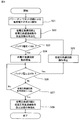
図4は、実施の形態2による車両用交流発電機の発電制御装置の動作を示すフローチャートである。図4に於いて、ステップS21では、パワー・オン・リセット回路104は、発電制御装置11の内部電源の電圧の立ち上がりを検知し、リセット信号を出力する。ステップS22に於いて、低電圧保護回路102と低電圧保護連続動作防止回路103は、パワー・オン・リセット回路104からのリセット信号を受けて有効化される。
FIG. 4 is a flowchart showing the operation of the power generation control device for the vehicle alternator according to the second embodiment. In FIG. 4, in step S <b> 21, the power-on / reset circuit 104 detects the rise of the voltage of the internal power supply of the power generation control device 11 and outputs a reset signal. In step S <b> 22, the low voltage protection circuit 102 and the low voltage protection continuous operation prevention circuit 103 are validated upon receiving a reset signal from the power-on reset circuit 104.
次に、ステップS23に於いて、低電圧保護回路102は、バッテリ17の出力電圧としてのバッテリ電圧と予め設定された所定の電圧VBLとを比較し、バッテリ電圧が所定の電圧VBLより小さいと判定すれば(Yes)、次のステップS24に進む。
Next, in step S23, the low voltage protection circuit 102 compares the battery voltage as the output voltage of the battery 17 with a predetermined voltage VBL set in advance, and determines that the battery voltage is smaller than the predetermined voltage VBL. If yes (Yes), the process proceeds to the next step S24.
ステップS24では、低電圧保護回路102が動作を開始し、電圧制御回路101によるトランジスタ15のスイッチング制御に関係なく、トランジスタ15をオンし、励磁電流を増加させて交流発電機本体100の発電電圧を上昇させる動作を開始する。
In step S24, the low-voltage protection circuit 102 starts operation, and regardless of the switching control of the transistor 15 by the voltage control circuit 101, the transistor 15 is turned on and the excitation current is increased to increase the generated voltage of the AC generator body 100. Start to move up.
次に、ステップS24に於いて、低電圧保護回路102は、バッテリ電圧と予め設定された所定の電圧VBLとを比較し、バッテリ電圧が所定の電圧VBL以上であると判定すれば(Yes)、ステップS25に進み、低電圧保護回路102は前述の動作を停止し、ステップS23に戻る。一方、ステップS24に於いて、バッテリ電圧が所定の電圧VBL以上ではないと判定すれば(No)、ステップS27に進む。
Next, in step S24, the low voltage protection circuit 102 compares the battery voltage with a predetermined voltage VBL set in advance, and determines that the battery voltage is equal to or higher than the predetermined voltage VBL (Yes). Proceeding to step S25, the low-voltage protection circuit 102 stops the above-described operation and returns to step S23. On the other hand, if it is determined in step S24 that the battery voltage is not equal to or higher than the predetermined voltage VBL (No), the process proceeds to step S27.
ステップS27に於いて、低電圧保護連続動作防止回路103は、低電圧保護回路102の動作時間と予め定められた所定の時間TVBLとを比較し、低電圧保護回路102の動作時間が所定の時間TVBLを超えていないと判定すれば(No)、ステップS26に戻る。一方、ステップS27に於いて、低電圧保護回路102の動作時間が所定の時間TVBLを超えていると判定すれば(Yes)、ステップS28に進んで、低電圧保護連続動作防止回路103と低電圧保護回路102は無効化され、低電圧保護回路102の前述の動作は停止する。このようにして低電圧保護回路102が無効化されてその動作が停止するため、発電制御装置11は、電圧制御回路101による通常動作に復帰する。
In step S27, the low voltage protection continuous operation prevention circuit 103 compares the operation time of the low voltage protection circuit 102 with a predetermined time TVBL, and the operation time of the low voltage protection circuit 102 is a predetermined time. If it is determined that the TVBL is not exceeded (No), the process returns to step S26. On the other hand, if it is determined in step S27 that the operation time of the low voltage protection circuit 102 exceeds the predetermined time TVBL (Yes), the process proceeds to step S28, where the low voltage protection continuous operation prevention circuit 103 and the low voltage protection circuit 103 The protection circuit 102 is disabled, and the above-described operation of the low voltage protection circuit 102 is stopped. In this way, the low voltage protection circuit 102 is disabled and its operation stops, so that the power generation control device 11 returns to normal operation by the voltage control circuit 101.
ここで、ステップS28に於いて低電圧保護回路102は無効化されるため、再度、バッテリ電圧が予め設定された所定の電圧VBLより低くなった場合でも、低電圧保護回路102は動作することはない。
Here, since the low voltage protection circuit 102 is invalidated in step S28, the low voltage protection circuit 102 does not operate even when the battery voltage becomes lower than the predetermined voltage VBL set in advance again. Absent.
尚、ここでは、交流発電機本体100の発電電圧が予め設定された所定の電圧よりも小さいことを検出する手段として、後述するように、バッテリ電圧が所定の電圧VBLよりも小さいことを検出するようにしているが、交流発電機本体100の発電電圧を直接検出し、その発電電圧が所定の電圧よりも小さいことを検出するようにしてもよい。
Here, as described below, as means for detecting that the generated voltage of the AC generator main body 100 is smaller than a predetermined voltage, it is detected that the battery voltage is smaller than the predetermined voltage VBL as will be described later. However, the power generation voltage of the AC generator main body 100 may be directly detected to detect that the power generation voltage is smaller than a predetermined voltage.
実施の形態2に於いては、低電圧保護連続動作防止回路103が一度動作を行なえば、低電圧保護回路102と低電圧保護連続動作防止回路103は無効化される。これは、低電圧保護連続動作防止回路103が動作する場合は、例えばバッテリ電圧を検知する回路の故障等の何らかの異常状態である可能性が高いため、この状態に於いて発電電圧を強制的に高くする低電圧保護回路102を動作させることは好ましくないためである。
In the second embodiment, once the low voltage protection continuous operation prevention circuit 103 operates, the low voltage protection circuit 102 and the low voltage protection continuous operation prevention circuit 103 are invalidated. This is because when the low-voltage protection continuous operation prevention circuit 103 operates, there is a high possibility that it is in some abnormal state such as a failure of the circuit that detects the battery voltage. This is because it is not preferable to operate the low voltage protection circuit 102 to be increased.
低電圧保護回路102が所定の時間TVBLを超えて動作しても、バッテリ電圧、従って交流発電機本体100の発電電圧が所定の電圧を超えて上昇しない場合は、低電圧保護回路を無効化しても、安全な発電制御装置を得ることが可能となる。
If the battery voltage, and thus the generated voltage of the AC generator main body 100 does not rise beyond the predetermined voltage even if the low voltage protection circuit 102 operates for a predetermined time TVBL, the low voltage protection circuit is disabled. In addition, a safe power generation control device can be obtained.
以上述べた実施の形態2による車両用交流発電機の発電制御装置よれば、低電圧保護連続動作防止回路103が一度動作を行なえば、低電圧保護回路102と低電圧保護連続動作防止回路103は無効化されるので、例えばバッテリ電圧を検知する回路の故障等の何らかの異常状態であった場合に、低電圧保護回路102が動作することはなく、発電電圧を強制的に高くすることがなく発電制御装置11を安全に動作させることができる。
According to the power generation control device for a vehicle alternator according to Embodiment 2 described above, once the low voltage protection continuous operation prevention circuit 103 operates, the low voltage protection circuit 102 and the low voltage protection continuous operation prevention circuit 103 are Since it is invalidated, for example, in the case of some abnormal state such as a failure of a circuit that detects the battery voltage, the low voltage protection circuit 102 does not operate, and the generated voltage is not increased forcibly. The control device 11 can be operated safely.
その他の構成は、実施の形態1の場合と同様である。尚、低電圧保護連続動作防止回路103は、低電圧保護回路102の動作時間に代えてバッテリ電圧の低電圧状態の時間を計測し、バッテリ電圧の低電圧状態が予め設定された所定の時間を超えて継続したことを検知しときに、低電圧保護回路102の動作を停止させるように構成されていてもよい。
Other configurations are the same as those in the first embodiment. The low voltage protection continuous operation prevention circuit 103 measures the time of the low voltage state of the battery voltage instead of the operation time of the low voltage protection circuit 102, and determines the predetermined time when the low voltage state of the battery voltage is set in advance. It may be configured to stop the operation of the low voltage protection circuit 102 when it is detected that the operation has continued beyond the limit.
実施の形態3.
次に、実施の形態3による車両用交流発電機の発電制御装置について説明する。図5は、実施の形態3による車両用交流発電機の発電制御装置を示す構成図である。実施の形態3による車両用交流発電機の発電制御装置は、電圧制御回路101が発電制御装置11の外部、例えばECU(Engine Control Unit:エンジン制御装置)に設けられていることを特徴とする。その他の構成は、実施の形態2による交流発電機の発電制御装置と同様である。 Embodiment 3 FIG.
Next, a power generation control device for an automotive alternator according to Embodiment 3 will be described. FIG. 5 is a configuration diagram illustrating a power generation control device for an automotive alternator according to the third embodiment. The power generation control device for an automotive alternator according to Embodiment 3 is characterized in that thevoltage control circuit 101 is provided outside the power generation control device 11, for example, an ECU (Engine Control Unit). Other configurations are the same as those of the generator control device for the AC generator according to the second embodiment.
次に、実施の形態3による車両用交流発電機の発電制御装置について説明する。図5は、実施の形態3による車両用交流発電機の発電制御装置を示す構成図である。実施の形態3による車両用交流発電機の発電制御装置は、電圧制御回路101が発電制御装置11の外部、例えばECU(Engine Control Unit:エンジン制御装置)に設けられていることを特徴とする。その他の構成は、実施の形態2による交流発電機の発電制御装置と同様である。 Embodiment 3 FIG.
Next, a power generation control device for an automotive alternator according to Embodiment 3 will be described. FIG. 5 is a configuration diagram illustrating a power generation control device for an automotive alternator according to the third embodiment. The power generation control device for an automotive alternator according to Embodiment 3 is characterized in that the
実施の形態3による交流発電機の発電制御装置によれば、ECU側で発電制御を行うことで、エンジン及び車両の状態等の情報を発電制御に活用することが可能となり、車両用交流発電機の負荷の運転をきめ細かく制御することで快適な車両走行を提供することが可能となる。
According to the alternator power generation control device according to the third embodiment, by performing power generation control on the ECU side, it becomes possible to utilize information such as the state of the engine and the vehicle for power generation control. It is possible to provide comfortable vehicle travel by finely controlling the driving of the load.
また、電圧制御回路が車両用交流発電機の発電制御装置の外部に設けられても、リップル除去のためのローパスフィルタによる瞬間的な電圧低下に対応できない場合があるが、実施の形態3による交流発電機の発電制御装置によれば、定電圧保護回路と低電圧保護連続動作防止回路により交流発電機本体の電圧を上昇させることができ、安全で安定した動作を行うことができる発電制御装置を得ることが可能となる。
Further, even if the voltage control circuit is provided outside the power generation control device of the vehicle alternator, it may not be able to cope with an instantaneous voltage drop due to the low-pass filter for ripple removal. According to the power generation control device of the generator, the power generation control device that can raise the voltage of the AC generator main body by the constant voltage protection circuit and the low voltage protection continuous operation prevention circuit, and can perform a safe and stable operation. Can be obtained.
実施の形態4.
実施の形態4による車両用交流発電機の発電制御装置は、前述の実施の形態1から実施の形態3による車両用交流発電機の発電制御装置に於いて、予め設定される前述の所定の電圧VBLと、予め設定される前述の所定の時間TVBLを、発電制御装置11の外部に設けられた外部制御装置により設定することができるように構成されることを特徴とする。その他の構成は、実施の形態1による車両用交流発電機の発電制御装置、又は実施の形態2による車両用交流発電機の発電制御装置、又は実施の形態3による車両用交流発電機の発電制御装置と同様である。ここで、予め設定される所定の電圧VBLと、予め設定される所定の時間TVBLとを設定することができる外部制御装置は、例えば前述のECUであってもよく、或いはそれ以外の制御装置であってもよいことは勿論である。 Embodiment 4 FIG.
The power generation control device for the vehicle alternator according to the fourth embodiment is the above-described predetermined voltage set in advance in the power generation control device for the vehicle alternator according to the first to third embodiments. The VBL and the predetermined time TVBL set in advance can be set by an external control device provided outside the powergeneration control device 11. The other configurations are the power generation control device for the vehicle alternator according to the first embodiment, the power generation control device for the vehicle alternator according to the second embodiment, or the power generation control of the vehicle alternator according to the third embodiment. It is the same as the device. Here, the external control device that can set the predetermined voltage VBL set in advance and the predetermined time TVBL set in advance may be, for example, the above-described ECU, or other control device. Of course there may be.
実施の形態4による車両用交流発電機の発電制御装置は、前述の実施の形態1から実施の形態3による車両用交流発電機の発電制御装置に於いて、予め設定される前述の所定の電圧VBLと、予め設定される前述の所定の時間TVBLを、発電制御装置11の外部に設けられた外部制御装置により設定することができるように構成されることを特徴とする。その他の構成は、実施の形態1による車両用交流発電機の発電制御装置、又は実施の形態2による車両用交流発電機の発電制御装置、又は実施の形態3による車両用交流発電機の発電制御装置と同様である。ここで、予め設定される所定の電圧VBLと、予め設定される所定の時間TVBLとを設定することができる外部制御装置は、例えば前述のECUであってもよく、或いはそれ以外の制御装置であってもよいことは勿論である。 Embodiment 4 FIG.
The power generation control device for the vehicle alternator according to the fourth embodiment is the above-described predetermined voltage set in advance in the power generation control device for the vehicle alternator according to the first to third embodiments. The VBL and the predetermined time TVBL set in advance can be set by an external control device provided outside the power
実施の形態4による車両用交流発電機の発電制御装置によれば、発電制御装置の外部に設けられた外部制御装置により、所定の電圧VBLと所定の時間TVBLとを設定することができるので、交流発電機本体100の発電電圧の目標設定電圧が変更された場合でも、低電圧保護回路102と低電圧保護連続動作防止回路103とを何ら変更することなく、交流発電機本体100の発電電圧の目標設定電圧に対応させて容易に所定の電圧VBLと所定の時間TVBLとを設定することができる。
According to the power generation control device for a vehicle alternator according to Embodiment 4, the predetermined voltage VBL and the predetermined time TVBL can be set by the external control device provided outside the power generation control device. Even when the target setting voltage of the generator voltage of the alternator main body 100 is changed, the generated voltage of the alternator main body 100 can be changed without changing the low voltage protection circuit 102 and the low voltage protection continuous operation prevention circuit 103. The predetermined voltage VBL and the predetermined time TVBL can be easily set corresponding to the target setting voltage.
本願は、様々な例示的な実施の形態及び実施例が記載されているが、1つ、または複数の実施の形態に記載された様々な特徴、態様、及び機能は特定の実施の形態の適用に限られるのではなく、単独で、または様々な組み合わせで実施の形態に適用可能である。従って、例示されていない無数の変形例が、本願に開示される技術の範囲内において想定される。例えば、少なくとも1つの構成要素を変形する場合、追加する場合または省略する場合、さらには、少なくとも1つの構成要素を抽出し、他の実施の形態の構成要素と組み合わせる場合が含まれるものとする。
Although this application describes various exemplary embodiments and examples, various features, aspects, and functions described in one or more embodiments may be applied to particular embodiments. The present invention is not limited to this, and can be applied to the embodiments alone or in various combinations. Accordingly, innumerable modifications not illustrated are envisaged within the scope of the technology disclosed in the present application. For example, the case where at least one component is deformed, the case where the component is added or omitted, and the case where the at least one component is extracted and combined with the component according to another embodiment are included.
本願の交流発電機の発電制御装置は、自動車等の車両に搭載される交流発電機の分野、ひいては自動車等の車輛の分野に利用することができる。
The power generation control device for an AC generator of the present application can be used in the field of an AC generator mounted on a vehicle such as an automobile, and eventually in the field of a vehicle such as an automobile.
10 車両用交流発電機、100 交流発電機本体、11 発電制御装置、12 界磁コイル、13 電機子コイル、14 整流器、15 トランジスタ、16 還流ダイオード、17 バッテリ、101 電圧制御回路、102 低電圧保護回路、103 低電圧保護連続動作防止回路、104 パワー・オン・リセット回路、1001 プロセッサ、1002 記憶装置
10 AC generator for vehicle, 100 AC generator body, 11 generator controller, 12 field coil, 13 armature coil, 14 rectifier, 15 transistor, 16 freewheeling diode, 17 battery, 101 voltage control circuit, 102 low voltage protection Circuit, 103 low voltage protection continuous operation prevention circuit, 104 power on reset circuit, 1001 processor, 1002 storage device
Claims (5)
- 車両に搭載される交流発電機本体の界磁コイルに流れる励磁電流を制御し、前記交流発電機本体の発電電圧を制御するように構成された電圧制御回路と、
前記発電電圧若しくは前記発電電圧に基づく電圧が所定の電圧よりも低下したとき、前記電圧制御回路による前記発電電圧の制御とは無関係に、前記励磁電流を増大させて前記発電電圧を上昇させるように動作する低電圧保護回路と、
前記低電圧保護回路の前記動作が所定時間を超えて継続したとき、前記低電圧保護回路の前記動作を停止させるように動作する低電圧保護連続動作防止回路と、
を備えたことを特徴とする車両用交流発電機の発電制御装置。 A voltage control circuit configured to control an excitation current flowing in a field coil of an AC generator body mounted on a vehicle, and to control a generated voltage of the AC generator body;
When the generated voltage or a voltage based on the generated voltage is lower than a predetermined voltage, the excitation current is increased to increase the generated voltage regardless of the control of the generated voltage by the voltage control circuit. An operating low voltage protection circuit;
A low-voltage protection continuous operation prevention circuit that operates to stop the operation of the low-voltage protection circuit when the operation of the low-voltage protection circuit continues beyond a predetermined time;
A power generation control device for an AC generator for vehicles. - 少なくとも前記電圧制御回路と前記低電圧保護回路と前記低電圧保護連続動作防止回路に電力を供給する内部電源と、
前記内部電源の電圧の立ち上がりを検知してリセット信号を出力するリセット回路と、
を有し、
前記低電圧保護回路と前記低電圧保護連続動作防止回路は、前記リセット回路から出力された前記リセット信号により有効化され、且つ前記低電圧保護連続動作防止回路が前記低電圧保護回路の動作を停止させたときに無効化され、
前記低電圧保護回路は、前記無効化された後に前記発電電圧若しくは前記発電電圧に基づく電圧が前記所定の電圧よりも低下しても前記動作を行わないように構成されている、
ことを特徴とする請求項1に記載の車両用交流発電機の発電制御装置。 An internal power supply that supplies power to at least the voltage control circuit, the low voltage protection circuit, and the low voltage protection continuous operation prevention circuit;
A reset circuit that detects a rise of the voltage of the internal power supply and outputs a reset signal;
Have
The low voltage protection circuit and the low voltage protection continuous operation prevention circuit are enabled by the reset signal output from the reset circuit, and the low voltage protection continuous operation prevention circuit stops the operation of the low voltage protection circuit. Will be disabled when
The low voltage protection circuit is configured not to perform the operation even if the generated voltage or the voltage based on the generated voltage is lower than the predetermined voltage after being invalidated.
The power generation control device for an AC generator for a vehicle according to claim 1. - 前記リセット回路は、更に、前記内部電源の電圧の立ち下がりを検知してリセット信号を出力するように構成され、
前記低電圧保護回路と前記低電圧保護連続動作防止回路は、前記内部電源の電圧の立ち下がりを検知して前記リセット回路から出力された前記リセット信号によりリセットされるように構成されている、
ことを特徴とする請求項2に記載の車両用交流発電機の発電制御装置。 The reset circuit is further configured to detect a fall of the voltage of the internal power supply and output a reset signal,
The low voltage protection circuit and the low voltage protection continuous operation prevention circuit are configured to detect a fall of the voltage of the internal power supply and to be reset by the reset signal output from the reset circuit.
The power generation control device for a vehicle AC generator according to claim 2. - 前記電圧制御回路は、外部に設けられている、
ことを特徴とする請求項1から3のうちの何れか一項に記載の車両用交流発電機の発電制御装置。 The voltage control circuit is provided outside,
The power generation control device for an AC generator for a vehicle according to any one of claims 1 to 3. - 前記所定の電圧と前記所定の時間は、外部制御装置により設定可能に構成されている、
ことを特徴とする請求項1から4のうちの何れか一項に記載の車両用交流発電機の発電制御装置。 The predetermined voltage and the predetermined time are configured to be settable by an external control device.
The power generation control device for a vehicle alternator according to any one of claims 1 to 4, wherein
Priority Applications (5)
| Application Number | Priority Date | Filing Date | Title |
|---|---|---|---|
| EP18918760.2A EP3796545A4 (en) | 2018-05-15 | 2018-05-15 | Power generation control device for vehicle ac generator |
| US16/970,012 US11342870B2 (en) | 2018-05-15 | 2018-05-15 | Power generation controller for vehicle AC power generator |
| CN201880093259.1A CN112106290A (en) | 2018-05-15 | 2018-05-15 | Power generation control device for vehicle alternator |
| PCT/JP2018/018700 WO2019220526A1 (en) | 2018-05-15 | 2018-05-15 | Power generation control device for vehicle ac generator |
| JP2020518845A JP7058731B2 (en) | 2018-05-15 | 2018-05-15 | Power generation control device for vehicle alternator |
Applications Claiming Priority (1)
| Application Number | Priority Date | Filing Date | Title |
|---|---|---|---|
| PCT/JP2018/018700 WO2019220526A1 (en) | 2018-05-15 | 2018-05-15 | Power generation control device for vehicle ac generator |
Publications (1)
| Publication Number | Publication Date |
|---|---|
| WO2019220526A1 true WO2019220526A1 (en) | 2019-11-21 |
Family
ID=68540047
Family Applications (1)
| Application Number | Title | Priority Date | Filing Date |
|---|---|---|---|
| PCT/JP2018/018700 WO2019220526A1 (en) | 2018-05-15 | 2018-05-15 | Power generation control device for vehicle ac generator |
Country Status (5)
| Country | Link |
|---|---|
| US (1) | US11342870B2 (en) |
| EP (1) | EP3796545A4 (en) |
| JP (1) | JP7058731B2 (en) |
| CN (1) | CN112106290A (en) |
| WO (1) | WO2019220526A1 (en) |
Citations (4)
| Publication number | Priority date | Publication date | Assignee | Title |
|---|---|---|---|---|
| JPH05336682A (en) * | 1992-05-28 | 1993-12-17 | Suzuki Motor Corp | Vehicle generator controller |
| JP3283325B2 (en) | 1993-03-31 | 2002-05-20 | 富士通テン株式会社 | Alternator control device |
| JP2006246574A (en) * | 2005-03-01 | 2006-09-14 | Denso Corp | Power generation controller |
| JP2015065788A (en) * | 2013-09-26 | 2015-04-09 | 株式会社デンソー | Rotary electric machine for vehicle |
Family Cites Families (3)
| Publication number | Priority date | Publication date | Assignee | Title |
|---|---|---|---|---|
| JP3991983B2 (en) | 2003-12-19 | 2007-10-17 | 日産自動車株式会社 | Vehicle drive control device |
| JP4682901B2 (en) | 2006-04-04 | 2011-05-11 | 株式会社デンソー | Power generation control system |
| JP4450085B2 (en) * | 2008-03-17 | 2010-04-14 | 株式会社デンソー | Vehicle power generation control device |
-
2018
- 2018-05-15 EP EP18918760.2A patent/EP3796545A4/en not_active Withdrawn
- 2018-05-15 WO PCT/JP2018/018700 patent/WO2019220526A1/en unknown
- 2018-05-15 CN CN201880093259.1A patent/CN112106290A/en not_active Withdrawn
- 2018-05-15 JP JP2020518845A patent/JP7058731B2/en active Active
- 2018-05-15 US US16/970,012 patent/US11342870B2/en active Active
Patent Citations (5)
| Publication number | Priority date | Publication date | Assignee | Title |
|---|---|---|---|---|
| JPH05336682A (en) * | 1992-05-28 | 1993-12-17 | Suzuki Motor Corp | Vehicle generator controller |
| JP3283325B2 (en) | 1993-03-31 | 2002-05-20 | 富士通テン株式会社 | Alternator control device |
| JP2006246574A (en) * | 2005-03-01 | 2006-09-14 | Denso Corp | Power generation controller |
| JP4179296B2 (en) | 2005-03-01 | 2008-11-12 | 株式会社デンソー | Power generation control device |
| JP2015065788A (en) * | 2013-09-26 | 2015-04-09 | 株式会社デンソー | Rotary electric machine for vehicle |
Non-Patent Citations (1)
| Title |
|---|
| See also references of EP3796545A4 |
Also Published As
| Publication number | Publication date |
|---|---|
| US20210104962A1 (en) | 2021-04-08 |
| CN112106290A (en) | 2020-12-18 |
| EP3796545A4 (en) | 2021-04-07 |
| US11342870B2 (en) | 2022-05-24 |
| JP7058731B2 (en) | 2022-04-22 |
| JPWO2019220526A1 (en) | 2021-02-12 |
| EP3796545A1 (en) | 2021-03-24 |
Similar Documents
| Publication | Publication Date | Title |
|---|---|---|
| US6734653B2 (en) | Voltage regulator for alternator and method of controlling power generation of alternator | |
| JP4570982B2 (en) | Power generation control device and power generation device | |
| JP2006271136A (en) | Dc-dc converter device | |
| JP2005229756A (en) | Voltage generator, automobile, method for controlling voltage generator, method for controlling automobile, computer readable recording medium for storing program making computer execute control method | |
| JP5181666B2 (en) | Field winding type motor and control circuit for field winding type generator | |
| JP6308092B2 (en) | Electronic control unit | |
| JP5452654B2 (en) | Control device for vehicle alternator | |
| US20140306521A1 (en) | Method for operating a multi-voltage electrical system of a motor vehicle, a multi-voltage electrical system and means for implementing the method | |
| JP4143648B2 (en) | Field winding AC rotating electrical machine | |
| JP3997969B2 (en) | Power generation control device | |
| JP6232133B2 (en) | Electronic control unit | |
| JP2009142089A (en) | Power supply device for vehicle | |
| JP2010083420A (en) | Power source system of vehicular auxiliary machine | |
| JP2009100488A (en) | Alternator controller for vehicle | |
| CN113892159A (en) | Converter device and industrial machine | |
| WO2019220526A1 (en) | Power generation control device for vehicle ac generator | |
| JP4780171B2 (en) | Vehicle power generation control device | |
| KR20150116843A (en) | Method for operating an energy supply unit for an on-board power system of a motorvehicle | |
| KR102320892B1 (en) | Apparatus for preventing over current of converter system and method thereof | |
| JP6162445B2 (en) | Power converter | |
| JP7198169B2 (en) | switching power supply | |
| JP2009118657A (en) | Power supply device and electronic equipment equipped with the same | |
| JPH09294392A (en) | Drive system for bruchless motor | |
| JP4046108B2 (en) | Power generation control device | |
| JP2011167002A (en) | Device for power control |
Legal Events
| Date | Code | Title | Description |
|---|---|---|---|
| 121 | Ep: the epo has been informed by wipo that ep was designated in this application |
Ref document number: 18918760 Country of ref document: EP Kind code of ref document: A1 |
|
| ENP | Entry into the national phase |
Ref document number: 2020518845 Country of ref document: JP Kind code of ref document: A |
|
| NENP | Non-entry into the national phase |
Ref country code: DE |
|
| ENP | Entry into the national phase |
Ref document number: 2018918760 Country of ref document: EP Effective date: 20201215 |