WO2019216401A1 - 基板搬送ロボット及び基板保持ハンドの光軸ずれ検出方法 - Google Patents
基板搬送ロボット及び基板保持ハンドの光軸ずれ検出方法 Download PDFInfo
- Publication number
- WO2019216401A1 WO2019216401A1 PCT/JP2019/018686 JP2019018686W WO2019216401A1 WO 2019216401 A1 WO2019216401 A1 WO 2019216401A1 JP 2019018686 W JP2019018686 W JP 2019018686W WO 2019216401 A1 WO2019216401 A1 WO 2019216401A1
- Authority
- WO
- WIPO (PCT)
- Prior art keywords
- hand
- optical axis
- substrate
- target body
- turning
- Prior art date
- Legal status (The legal status is an assumption and is not a legal conclusion. Google has not performed a legal analysis and makes no representation as to the accuracy of the status listed.)
- Ceased
Links
Images





Classifications
-
- H—ELECTRICITY
- H10—SEMICONDUCTOR DEVICES; ELECTRIC SOLID-STATE DEVICES NOT OTHERWISE PROVIDED FOR
- H10P—GENERIC PROCESSES OR APPARATUS FOR THE MANUFACTURE OR TREATMENT OF DEVICES COVERED BY CLASS H10
- H10P72/00—Handling or holding of wafers, substrates or devices during manufacture or treatment thereof
- H10P72/50—Handling or holding of wafers, substrates or devices during manufacture or treatment thereof for positioning, orientation or alignment
- H10P72/53—Handling or holding of wafers, substrates or devices during manufacture or treatment thereof for positioning, orientation or alignment using optical controlling means
-
- B—PERFORMING OPERATIONS; TRANSPORTING
- B25—HAND TOOLS; PORTABLE POWER-DRIVEN TOOLS; MANIPULATORS
- B25J—MANIPULATORS; CHAMBERS PROVIDED WITH MANIPULATION DEVICES
- B25J9/00—Program-controlled manipulators
- B25J9/16—Program controls
- B25J9/1679—Program controls characterised by the tasks executed
- B25J9/1692—Calibration of manipulator
-
- B—PERFORMING OPERATIONS; TRANSPORTING
- B25—HAND TOOLS; PORTABLE POWER-DRIVEN TOOLS; MANIPULATORS
- B25J—MANIPULATORS; CHAMBERS PROVIDED WITH MANIPULATION DEVICES
- B25J11/00—Manipulators not otherwise provided for
- B25J11/0095—Manipulators transporting wafers
-
- B—PERFORMING OPERATIONS; TRANSPORTING
- B25—HAND TOOLS; PORTABLE POWER-DRIVEN TOOLS; MANIPULATORS
- B25J—MANIPULATORS; CHAMBERS PROVIDED WITH MANIPULATION DEVICES
- B25J13/00—Controls for manipulators
- B25J13/08—Controls for manipulators by means of sensing devices, e.g. viewing or touching devices
- B25J13/088—Controls for manipulators by means of sensing devices, e.g. viewing or touching devices with position, velocity or acceleration sensors
- B25J13/089—Determining the position of the robot with reference to its environment
-
- B—PERFORMING OPERATIONS; TRANSPORTING
- B25—HAND TOOLS; PORTABLE POWER-DRIVEN TOOLS; MANIPULATORS
- B25J—MANIPULATORS; CHAMBERS PROVIDED WITH MANIPULATION DEVICES
- B25J19/00—Accessories fitted to manipulators, e.g. for monitoring, for viewing; Safety devices combined with or specially adapted for use in connection with manipulators
- B25J19/02—Sensing devices
- B25J19/021—Optical sensing devices
-
- B—PERFORMING OPERATIONS; TRANSPORTING
- B25—HAND TOOLS; PORTABLE POWER-DRIVEN TOOLS; MANIPULATORS
- B25J—MANIPULATORS; CHAMBERS PROVIDED WITH MANIPULATION DEVICES
- B25J9/00—Program-controlled manipulators
- B25J9/16—Program controls
- B25J9/1674—Program controls characterised by safety, monitoring, diagnostic
-
- H—ELECTRICITY
- H10—SEMICONDUCTOR DEVICES; ELECTRIC SOLID-STATE DEVICES NOT OTHERWISE PROVIDED FOR
- H10P—GENERIC PROCESSES OR APPARATUS FOR THE MANUFACTURE OR TREATMENT OF DEVICES COVERED BY CLASS H10
- H10P72/00—Handling or holding of wafers, substrates or devices during manufacture or treatment thereof
- H10P72/06—Apparatus for monitoring, sorting, marking, testing or measuring
- H10P72/0606—Position monitoring, e.g. misposition detection or presence detection
-
- H—ELECTRICITY
- H10—SEMICONDUCTOR DEVICES; ELECTRIC SOLID-STATE DEVICES NOT OTHERWISE PROVIDED FOR
- H10P—GENERIC PROCESSES OR APPARATUS FOR THE MANUFACTURE OR TREATMENT OF DEVICES COVERED BY CLASS H10
- H10P72/00—Handling or holding of wafers, substrates or devices during manufacture or treatment thereof
- H10P72/30—Handling or holding of wafers, substrates or devices during manufacture or treatment thereof for conveying, e.g. between different workstations
- H10P72/33—Handling or holding of wafers, substrates or devices during manufacture or treatment thereof for conveying, e.g. between different workstations into and out of processing chamber
- H10P72/3302—Mechanical parts of transfer devices
-
- H—ELECTRICITY
- H10—SEMICONDUCTOR DEVICES; ELECTRIC SOLID-STATE DEVICES NOT OTHERWISE PROVIDED FOR
- H10P—GENERIC PROCESSES OR APPARATUS FOR THE MANUFACTURE OR TREATMENT OF DEVICES COVERED BY CLASS H10
- H10P72/00—Handling or holding of wafers, substrates or devices during manufacture or treatment thereof
- H10P72/30—Handling or holding of wafers, substrates or devices during manufacture or treatment thereof for conveying, e.g. between different workstations
- H10P72/34—Handling or holding of wafers, substrates or devices during manufacture or treatment thereof for conveying, e.g. between different workstations the wafers being stored in a carrier, involving loading and unloading
- H10P72/3402—Mechanical parts of transfer devices
-
- H—ELECTRICITY
- H10—SEMICONDUCTOR DEVICES; ELECTRIC SOLID-STATE DEVICES NOT OTHERWISE PROVIDED FOR
- H10P—GENERIC PROCESSES OR APPARATUS FOR THE MANUFACTURE OR TREATMENT OF DEVICES COVERED BY CLASS H10
- H10P72/00—Handling or holding of wafers, substrates or devices during manufacture or treatment thereof
- H10P72/50—Handling or holding of wafers, substrates or devices during manufacture or treatment thereof for positioning, orientation or alignment
-
- H—ELECTRICITY
- H10—SEMICONDUCTOR DEVICES; ELECTRIC SOLID-STATE DEVICES NOT OTHERWISE PROVIDED FOR
- H10P—GENERIC PROCESSES OR APPARATUS FOR THE MANUFACTURE OR TREATMENT OF DEVICES COVERED BY CLASS H10
- H10P72/00—Handling or holding of wafers, substrates or devices during manufacture or treatment thereof
- H10P72/70—Handling or holding of wafers, substrates or devices during manufacture or treatment thereof for supporting or gripping
- H10P72/76—Handling or holding of wafers, substrates or devices during manufacture or treatment thereof for supporting or gripping using mechanical means, e.g. clamps or pinches
- H10P72/7602—Handling or holding of wafers, substrates or devices during manufacture or treatment thereof for supporting or gripping using mechanical means, e.g. clamps or pinches the wafers being placed on a robot blade or gripped by a gripper for conveyance
-
- G—PHYSICS
- G05—CONTROLLING; REGULATING
- G05B—CONTROL OR REGULATING SYSTEMS IN GENERAL; FUNCTIONAL ELEMENTS OF SUCH SYSTEMS; MONITORING OR TESTING ARRANGEMENTS FOR SUCH SYSTEMS OR ELEMENTS
- G05B2219/00—Program-control systems
- G05B2219/30—Nc systems
- G05B2219/37—Measurements
- G05B2219/37283—Photoelectric sensor
Definitions
- the present invention relates to a technique for detecting an optical axis shift of a photoelectric sensor provided in a substrate holding hand in a substrate transport robot.
- a substrate transfer robot provided with a transmissive photoelectric sensor at the tip of a substrate holding hand.
- This photoelectric sensor is used to detect the presence or absence of a substrate in each slot, for example, by detecting the edge of the substrate accommodated in each slot of the carrier.
- the transmission type photoelectric sensor includes a projector and a light receiver, which are attached to the substrate holding hand with high accuracy.
- the positional deviation from the ideal position of the optical axis connecting the projector and the light receiver has been measured by a dedicated measuring device, stored in the controller, and used for controlling the robot by the controller.
- a method has been proposed in which the position of the optical axis of the photoelectric sensor is measured by the robot itself.
- Patent Documents 1 and 2 disclose this type of technology.
- a teaching jig including a small disk is placed at the mounting position of the substrate, and the edge of the small disk is detected by a photoelectric sensor provided in the hand.
- the present invention has been made in view of the above circumstances, and an object of the present invention is to easily and accurately determine the positional deviation of the optical axis from the ideal position as compared with the methods described in Patent Document 1 and Patent Document 2. It is to propose technology.
- An optical axis misalignment detection method for a substrate holding hand is provided at a hand that holds a substrate, a robot arm that includes a pivot axis of the hand, and that displaces the hand, and a tip of the hand.
- a method for detecting a deviation of an optical axis of the photoelectric sensor from an ideal optical axis defined in the hand Obtaining a reference turning position of the hand around the turning axis such that the ideal optical axis extends in a certain horizontal first direction;
- a first target body is detected by the photoelectric sensor while the hand is moved in a radial direction around the turning axis at a predetermined first turning position with respect to the reference turning position, and the first target body is detected.
- Performing a series of second search processes to obtain the position of the hand in the second direction as a second detection position when Detecting an inclination of the optical axis from the ideal optical axis based on a difference between the first detection position and the second detection position;
- the distance in the second direction from the pivot axis to the first target body is equal to the distance in the second direction from the pivot axis to the second target body,
- the intersection position of the optical axis and the first target body on the hand is different from the intersection position of the optical axis and the second target body.
- An optical axis misalignment detection method for a substrate holding hand includes a hand for holding a substrate, a robot arm for displacing the hand, and a photoelectric sensor provided at the tip of the hand.
- a method for detecting a deviation of the optical axis of the photoelectric sensor from the ideal optical axis defined in the hand The hand is moved to a predetermined substrate mounting position by advancing in a horizontal second direction orthogonal to the first direction in a posture in which the ideal optical axis extends in a horizontal first direction, and the hand is moved from the hand to the predetermined position.
- a position perpendicular to the center of the substrate held by the hand is defined as a hand center, and the hand is placed at a distance between the substrate center and the ideal optical axis from the substrate placement position.
- the photoelectric sensor searches for the edge of the substrate while moving the hand forward and backward in the second direction, and the position of the hand in the second direction when the edge of the substrate is detected in the search is used as a detection position. Seeking and Detecting a displacement of the optical axis from the ideal optical axis based on a difference between the reference position and the detection position.
- a substrate transfer robot having a hand holding a substrate, a robot arm including a pivot axis of the hand and displacing the hand, and a photoelectric sensor provided at a tip of the hand, and an ideal optical axis is defined for the hand
- a calibration jig having a first target body and a second target body
- the controller is A reference turning position of the hand with the turning axis as a turning center such that the ideal optical axis extends in a certain horizontal first direction is acquired, and the hand is set to a predetermined reference with respect to the reference turning position.
- a first search is performed to detect the first target body with the photoelectric sensor while moving in a radial direction around the turning axis at the first turning position, and the hand is set to a predetermined second with respect to the reference turning position.
- a robot control unit for operating the robot body to perform a second search for detecting a second target body with the photoelectric sensor while moving in a radial direction around the turning axis at a turning position; The position of the hand in the horizontal second direction orthogonal to the first direction when the first target body is detected in the first search is obtained as a first detection position, and the second target is obtained in the second search.
- the position of the hand in the second direction when the body is detected is obtained as a second detection position, and based on the difference between the first detection position and the second detection position, the optical axis is determined from the ideal optical axis.
- a substrate transfer robot includes a hand that holds a substrate, a robot arm that displaces the hand, a robot main body that includes a photoelectric sensor provided at a tip portion of the hand, A substrate placement unit provided at the substrate placement position and a controller are provided. And the controller An ideal optical axis is defined for the hand, and a position that overlaps in the vertical direction with the center of the substrate held by the hand in the hand is defined as a hand center.
- the hand is advanced to the substrate placement position in a horizontal second direction orthogonal to the first direction in a posture in which the ideal optical axis extends in a horizontal first direction, and from the hand to the substrate placement unit Transferring the substrate, moving the hand from the substrate mounting position to a position retracted in the second direction by a distance obtained by adding a radius of the substrate to a distance between the center of the hand and the ideal optical axis,
- a robot controller that operates the robot body so as to search the edge of the substrate by the photoelectric sensor while moving the hand forward and backward in the second direction;
- the position in the second direction when the hand is in the retracted position is obtained as a reference position, and the position in the second direction of the hand when the edge of the substrate is detected in the search is obtained as a detection position.
- an optical axis positional deviation detecting unit that detects a positional deviation of the optical axis from the ideal optical axis based on a difference between the reference position and the detection position.
- the present invention it is possible to detect the deviation of the optical axis of the substrate holding hand from the ideal position in a simpler and more accurate manner than in the past.
- FIG. 1 is a schematic side view of a substrate transfer robot according to an embodiment of the present invention.
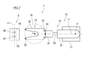
- FIG. 2 is a schematic plan view of the substrate transfer robot shown in FIG.
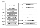
- FIG. 3 is a diagram illustrating a configuration of a control system of the substrate transfer robot.
- FIG. 4 is a diagram for explaining a method of detecting the inclination of the optical axis.
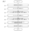
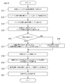
- FIG. 5 is a flowchart of an optical axis tilt detection process.
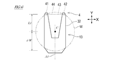
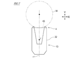
- FIG. 6 is a diagram for explaining a method of detecting the positional deviation of the optical axis.
- FIG. 7 is a diagram for explaining a method of detecting the positional deviation of the optical axis.
- FIG. 8 is a flowchart of the detection process of the positional deviation of the optical axis.
- FIG. 1 is a schematic side view of a substrate transfer robot according to an embodiment of the present invention.
- FIG. 2 is a schematic plan view of the substrate transfer robot shown in FIG.
- FIG. 3 is
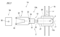
- FIG. 9 is a plan view showing a substrate transfer robot according to the first modification.
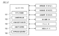
- FIG. 10 is a diagram showing a configuration of a control system of the substrate transfer robot shown in FIG.
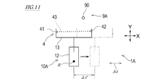
- FIG. 11 is a diagram for explaining a method of detecting the tilt of the optical axis by the substrate transport robot according to the first modification.
- FIG. 12 is a plan view showing a substrate transfer robot according to the second modification.
- FIG. 13 is a diagram for explaining an optical axis tilt detection process performed by the substrate transfer robot according to the second modification.
- FIG. 14 is a diagram for explaining an optical axis tilt detection process performed by the substrate transfer robot according to the second modification.
- FIG. 15 is a diagram for explaining the optical axis tilt detection processing by the substrate transport robot according to the second modification.
- FIG. 10 is a diagram showing a configuration of a control system of the substrate transfer robot shown in FIG.
- FIG. 11 is a diagram for explaining a method of detecting the tilt of the optical axis by the substrate transport robot
- FIG. 16 is a side view showing a configuration of a calibration jig having a function as a positioning jig.
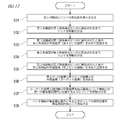
- FIG. 17 is a flowchart of the automatic teaching process of the reference turning position of the substrate transfer robot according to the third modification.
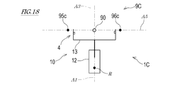
- FIG. 18 is a diagram for explaining automatic teaching processing of the reference turning position by the substrate transfer robot according to the third modification.
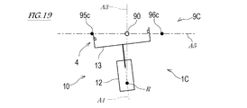
- FIG. 19 is a diagram for explaining automatic teaching processing of the reference turning position by the substrate transfer robot according to the third modification.
- FIG. 20 is a diagram for explaining automatic teaching processing of the reference turning position by the substrate transfer robot according to the third modification.
- FIG. 1 is a schematic side view of a substrate transfer robot 1 according to an embodiment of the present invention
- FIG. 2 is a schematic plan view of the substrate transfer robot 1 shown in FIG.
- the substrate transfer robot 1 shown in FIGS. 1 and 2 includes a robot body 10, a controller 15 that controls the operation of the robot body 10, and a calibration jig 9.
- the substrate transport robot 1 carries in (loads) and unloads the substrate W with respect to a substrate placement unit (not shown).
- the substrate transfer robot 1 may be provided in a system for transferring various substrates W such as an EFEM (Equipment Front End Module), a sorter, and a substrate processing system.
- EFEM Equipment Front End Module
- the robot body 10 includes a base 11, a robot arm (hereinafter referred to as “arm 12”) supported by the base 11, and a substrate holding hand (hereinafter referred to as “the arm 12”) connected to the distal end portion of the arm 12. And a transmissive photoelectric sensor 4 provided on the hand 13.
- a transmissive photoelectric sensor is employed as the photoelectric sensor 4, but a retroreflective photoelectric sensor may be employed instead.
- the arm 12 includes a first link 21 extending in the horizontal direction and a second link 22 connected to the first link 21 via a translational joint.
- the first link 21 is provided with a translation device 63, and the second link 22 translates in parallel to the longitudinal direction of the first link 21 with respect to the first link 21 by the operation of the translation device 63.
- the translation device 63 includes, for example, a linear motion mechanism (not shown) such as a rail and slider, a rack and pinion, a ball screw, or a cylinder, and a servo motor M3 (see FIG. 3) as a drive unit.
- a linear motion mechanism such as a rail and slider, a rack and pinion, a ball screw, or a cylinder, and a servo motor M3 (see FIG. 3) as a drive unit.
- the configuration of the translation device 63 is not limited to the above.
- the proximal end of the arm 12 is supported by the base 11 so that it can be raised and lowered.
- the lifting shaft 23 connected to the proximal end portion of the arm 12 expands and contracts, and the arm 12 moves up and down with respect to the base 11.
- the elevating device 61 includes, for example, a linear motion mechanism (not shown) that expands and contracts the elevating shaft 23 from the base 11, and a servo motor M1 (see FIG. 3) as a drive unit.
- the arm 12 pivots around the pivot axis R with respect to the base 11 by the operation of the pivoting device 62.
- the pivot axis R of the arm 12 substantially coincides with the axis of the lifting shaft 23.
- the turning device 62 includes, for example, a gear mechanism (not shown) that rotates the first link 21 around the turning axis R, and a servo motor M2 (see FIG. 3) as a drive unit.
- a gear mechanism not shown
- a servo motor M2 see FIG. 3
- the configurations of the lifting device 61 and the turning device 62 are not limited to the above.
- the hand 13 includes a base portion 31 connected to the distal end portion of the arm 12 and a blade 32 fixed to the base portion 31.
- the blade 32 is a thin plate member having a Y-shape (or U-shape) with a tip portion divided into two forks.
- the main surface of the blade 32 is horizontal, and a plurality of support pads 33 that support the substrate W are provided on the blade 32.
- the plurality of support pads 33 are disposed so as to contact the edge of the substrate W placed on the blade 32.
- a pusher 34 is provided on the proximal end side of the blade 32 in the hand 13. The substrate W placed on the blade 32 is gripped between the pusher 34 and the support pad 33 disposed at the tip of the blade 32.
- the hand 13 transports the substrate W while holding the substrate W in a horizontal posture
- the hand 13 may be one that can hold the substrate W in a vertical posture.
- the holding method of the substrate W of the hand 13 according to the present embodiment is an edge gripping method, but instead of the edge gripping method, a known holding method of the substrate W such as a suction method, a drop-in method, and a placement method is adopted. May be.
- the hand 13 is provided with at least one set of photoelectric sensors 4.
- the photoelectric sensor 4 is provided on the back surface of the tip portion of the blade 32 which is divided into two forks.
- the photoelectric sensor 4 includes a light projector 41 provided at one of the bifurcated tip portions of the blade 32 and a light receiver 42 provided at the other.
- the projector 41 and the light receiver 42 are separated from each other in a direction parallel to the main surface of the blade 32 (that is, in the horizontal direction).
- the projector 41 includes a light source that projects light serving as a detection medium.
- the light receiver 42 includes a light receiving element that receives the projection light from the projector 41 and converts it into an electrical signal.
- the light projector 41 and the light receiver 42 are arranged to face each other, and the light emitted from the light projector 41 travels linearly and enters the light incident window of the light receiver of the light receiver 42.
- the optical axis 43 of the light exiting the projector 41 is indicated by a chain line.
- the calibration jig 9 includes two target bodies 91 and 92 and target moving devices 93 and 94 that individually move the target bodies 91 and 92. It is desirable that the target bodies 91 and 92 have a vertically extending pin, shaft, or column shape in order to ensure a width at the height detected by the photoelectric sensor 4 and to further reduce the detection position error. .
- the shape of the target bodies 91 and 92 is not limited to this.
- the target moving devices 93 and 94 are arranged between a region where the target bodies 91 and 92 can be detected by the photoelectric sensor 4 (detectable region) and a region which is lower than that and cannot be detected by the photoelectric sensor 4 (non-detectable region). Anything can be used.
- the target moving devices 93 and 94 include, for example, a linear motion mechanism such as a rack and pinion and an electric motor as a drive unit of the linear motion mechanism. However, the target moving devices 93 and 94 are not limited to this.
- the target moving devices 93 and 94 are communicably connected to the controller 15, and the operations of the target moving devices 93 and 94 are controlled by the jig control unit 152 of the controller 15.
- a straight line through which the two target bodies 91 and 92 pass is defined as a target reference line A2 (see FIG. 2).
- the separation distance ⁇ d parallel to the target reference line A 2 of the two target bodies 91 and 92 is known, and ⁇ d is shorter than the length of the optical axis 43.
- FIG. 3 is a diagram illustrating a configuration of a control system of the substrate transfer robot 1.
- 3 includes a robot controller 151 that controls the operation of the robot body 10, a jig controller 152, an optical axis inclination detector 153, an optical axis displacement detector 154, and a reference turning position acquisition.
- Each functional unit with the unit 156 is included.
- the controller 15 includes an optical axis deviation storage unit 155 that stores information regarding the deviation of the optical axis 43.
- the controller 15 is a so-called computer, and includes, for example, an arithmetic processing device (processor) such as a microcontroller, CPU, MPU, PLC, DSP, ASIC, or FPGA, and a storage device such as ROM or RAM (both shown in the figure). Not shown).
- the storage device stores a program executed by the arithmetic processing unit, various fixed data, and the like.
- the program stored in the storage device includes the rotation axis search program according to the present embodiment.
- the storage device stores teaching data for controlling the operation of the arm 12, data relating to the shape and dimensions of the arm 12 and the hand 13, data relating to the shape and dimensions of the substrate W held by the hand 13, and the like. Yes.
- the arithmetic processing unit reads out and executes software such as a program stored in the storage device, so that processing for realizing the above-described functional unit is performed.
- the controller 15 may execute each process by centralized control by a single computer, or may execute each process by distributed control by cooperation of a plurality of computers.
- the controller 15 is connected to the servo motor M1 of the lifting device 61 of the arm 12, the servo motor M2 of the turning device 62, and the servo motor M3 of the translation device 63.
- the servo motors M1 to M3 are provided with position detectors E1 to E3 that detect the rotation angle of the output shaft, and the detection signals of the position detectors E1 to E3 are output to the controller 15.
- a pusher 34 of the hand 13 is also connected to the controller 15.
- the robot control unit 151 of the controller 15 then teaches the pose (that is, the position and orientation in space) of the hand 13 specified from the rotational position detected by each of the position detectors E1 to E3 and the teaching stored in the storage unit. Based on the data, a target pose after a predetermined control time is calculated, and the servo motors M1 to M3 are operated so that the hand 13 becomes the target pose after the predetermined control time.
- optical axis deviation detection method [Optical axis deviation detection method]
- the optical axis deviation detection method of the photoelectric sensor 4 provided on the hand 13 executed by the substrate transport robot 1 having the above-described configuration will be described.
- the hand 13 has a hand axis A1 and a hand center C defined therein.
- the hand axis A1 is an axis extending linearly in parallel with the longitudinal direction of the hand 13, and the blade 32 is formed in line symmetry with the hand axis A1 as a symmetry axis in plan view.
- the hand axis A1 is parallel to the extending / contracting direction of the arm 12, and the hand 13 moves parallel to the hand axis A1.
- the hand center C is a perpendicular line overlapping the center of the substrate W held by the hand 13 in the hand 13.
- the light projector 41 and the light receiver 42 of the photoelectric sensor 4 are attached to the hand 13 with high accuracy. Even so, the actual optical axis 43 may deviate from the designed ideal optical axis 44 due to mounting errors and individual differences between the projector 41 and the light receiver 42.
- the deviation of the optical axis 43 includes the inclination of the optical axis 43 from the ideal optical axis 44 and the positional deviation of the optical axis 43 from the ideal optical axis 44 in the hand axis A1 direction.
- the optical axis tilt detection unit 153 of the controller 15 detects the tilt of the optical axis 43 from the ideal optical axis 44, and the optical axis position deviation detection unit 154 of the controller 15 detects the light.
- a positional deviation in the direction parallel to the hand axis A1 from the ideal optical axis 44 of the axis 43 is detected, and the robot controller 151 operates the robot body 10 in consideration of the deviation of these optical axes 43.
- FIG. 4 is a diagram illustrating a method for detecting the tilt of the optical axis 43
- FIG. 5 is a flowchart of a process for detecting the tilt of the optical axis 43 by the substrate transport robot 1.
- a certain horizontal direction is defined as a first direction X
- a horizontal direction orthogonal to the first direction X is defined as a second direction Y.
- the calibration jig 9 is positioned so that the target reference line A2 is parallel to the first direction X. That is, the distance in the second direction Y from the turning axis R of the hand 13 to the first target body 91 is equal to the distance in the second direction Y from the turning axis R to the second target body 92.
- the controller 15 first acquires the reference turning position of the hand 13 (step S1).
- the hand 13 in the predetermined standby position is a reference turning position in which the extending direction of the ideal optical axis 44 is the first direction X and the extending direction of the hand axis A1 is the second direction Y. And away from the target bodies 91 and 92 in the second direction Y. If the positional relationship between the calibration jig 9 and the robot body 10 is known, the reference turning position of the hand 13 is known.
- the reference turning position acquisition unit 156 acquires a pre-stored reference turning position or a taught reference turning position, and the robot control unit 151 operates the robot body 10 so that the hand 13 becomes the reference turning position.
- step S2 the controller 15 performs a first search process (step S2).
- the controller 15 moves the robot body 10 so that the hand 13 moves in the radial direction around the turning axis R at the reference turning position until the first target body 91 is detected by the photoelectric sensor 4. Make it work.
- the hand 13 moves in the second direction Y.
- the controller 15 operates the target moving devices 93 and 94 so that the first target body 91 is located in the detectable region and the second target body 92 is located in the undetectable region.
- the controller 15 obtains the position of the hand 13 in the second direction Y when the first target body 91 is detected in the first search process, and stores it as the first detection position (step S3).
- the controller 15 operates the robot body 10 so that the hand 13 moves to the standby position.
- step S4 the controller 15 performs a second search process.
- the controller 15 moves the robot body 10 so that the hand 13 moves in the radial direction around the turning axis R at the reference turning position until the second target body 92 is detected by the photoelectric sensor 4. Make it work.
- the hand 13 moves in the second direction Y.
- the controller 15 operates the target moving devices 93 and 94 so that the first target body 91 is located in the undetectable area and the second target body 92 is located in the detectable area.
- the controller 15 obtains the position in the second direction Y of the hand 13 when the second target body 92 is detected in the second search process, and stores it as the second detection position (step S5).
- the controller 15 operates the robot body 10 so that the hand 13 moves to the standby position.
- the controller 15 obtains the inclination angle ⁇ of the optical axis 43 from the ideal optical axis 44 from the first detection position and the second detection position (step S6).
- the following equation is established among the tilt angle ⁇ of the optical axis 43, the difference ⁇ L (not shown) between the first detection position and the second detection position, and the separation distance ⁇ d between the target bodies 91 and 92.
- tan ⁇ ⁇ L / ⁇ d Therefore, the controller 15 obtains a difference ⁇ L between the first detection position and the second detection position, and uses the above equation to determine the ideal of the optical axis 43 based on the difference ⁇ L and the separation distance ⁇ d between the target bodies 91 and 92.
- An inclination angle ⁇ from the optical axis 44 is obtained.
- the controller 15 determines that there is no inclination of the optical axis 43 if the inclination angle ⁇ is substantially zero, and there is an inclination of the optical axis 43 if the inclination angle ⁇ is not substantially zero (that is, It may be determined that the inclination of the optical axis 43 has been detected.
- substantially 0 is not strictly limited to 0, and may include a value of a predetermined adjustment range from 0 to each of the plus side and the minus side.
- the controller 15 stores the obtained inclination angle ⁇ in the optical axis deviation storage unit 155 (step S7), and ends the process.
- FIG. 8 is a flowchart of a process for detecting the positional deviation of the optical axis 43 by the substrate transfer robot 1.
- the hand 13 of the robot body 10 holds the substrate W, is in an orientation in which the extending direction of the ideal optical axis 44 is the first direction X, and the extending direction of the hand axis A1 is the second direction Y. It is in a position retracted from the mounting portion in the second direction Y.
- the substrate placement unit is not particularly limited as long as the substrate W can be placed, such as a substrate boat, a substrate carrier, a substrate tray, a stage of a substrate processing apparatus, and an aligner.
- the controller 15 first operates the robot body 10 so as to transfer the substrate W from the hand 13 to the substrate platform (step S11).
- the controller 15 extends the arm 12 and moves the hand 13 in the second direction Y to move the blade 32 above the substrate platform, and then lowers the arm 12 to move the blade 32. Is moved below the substrate placement portion.
- the substrate W is transferred from the hand 13 to the substrate platform.
- the position in the second direction Y of the hand 13 when the substrate W is placed on the substrate placement unit is referred to as a “substrate placement position”.
- the distance L1 from the hand center C to the ideal optical axis 44 in the direction parallel to the hand axis A1 and the radius ⁇ W of the substrate W are both known values and stored in the controller 15 in advance.
- the controller 15 operates the robot body 10 so that the hand 13 moves backward in the second direction Y by the sum of the distance L1 and the radius ⁇ W (L1 + ⁇ W) from the substrate placement position. (Step S12).
- the controller 15 stores the position of the hand 13 in the second direction Y as a reference position (step S13).
- the controller 15 turns on the photoelectric sensor 4 and operates the robot body 10 to raise the hand 13 from the reference position until the ideal optical axis 44 moves from below the substrate W to above the substrate W (Ste S14). If the substrate W is not detected (NO in step S15), the controller 15 determines that the optical axis 43 is displaced from the ideal optical axis 44 toward the hand center C (step S16). If the substrate W is detected (YES in step S15), the controller 15 determines that the optical axis 43 coincides with the ideal optical axis 44 or is shifted to the opposite side of the hand center C (step S17).
- the controller 15 operates the robot body 10 so that the photoelectric sensor 4 searches for the edge of the substrate W while the hand 13 is advanced or retracted in the second direction Y (step). S18).
- the arm 12 is turned on with the photoelectric sensor 4 turned on when searching for the edge of the substrate W. Are extended and the arms 12 are raised and lowered repeatedly.
- the photoelectric sensor 4 is turned on when searching for the edge of the substrate W.
- the controller 15 stores the position of the hand 13 in the second direction Y when the edge of the substrate W is detected as a detection position (step S19).
- the controller 15 obtains the difference between the reference position and the detection position as a positional deviation amount of the optical axis 43 from the ideal optical axis 44 in a direction parallel to the hand axis A1 (step S20).
- the controller 15 determines that there is no positional deviation of the optical axis 43 if the positional deviation amount is substantially zero, and if the positional deviation amount is not substantially zero, there is a positional deviation of the optical axis 43 ( That is, it may be determined that the positional deviation of the optical axis 43 has been detected.
- the controller 15 stores the positional deviation amount in the optical axis deviation storage unit 155 (step S21), and ends the process.
- the controller 15 uses the tilt angle ⁇ of the optical axis 43 and the amount of positional deviation of the optical axis 43 stored in the optical axis deviation storage unit 155 to control the operation of the robot body 10. That is, the controller 15 generates an operation command for the robot body 10 so that the tilt angle ⁇ of the optical axis 43 and the positional deviation amount of the optical axis 43 are calibrated.
- the substrate transport robot 1 is provided at the hand 13 that holds the substrate W, the arm 12 that includes the turning axis R of the hand 13 and that displaces the hand 13, and the tip of the hand 13.
- the robot body 10 having the photoelectric sensor 4, the calibration jig 9 having the first target body 91 and the second target body 92, and the controller 15 are provided.
- the calibration jig 9 according to this embodiment includes a first target moving device 93 that moves the first target body 91 from a detectable range of the photoelectric sensor 4 to a non-detectable range, and a second target body 92 of the photoelectric sensor 4.
- a second target moving device 94 for moving from the detectable range to the undetectable range is further included.
- the first target body 91 and the second target body 92 are aligned in the first direction X, and the first target body 91 and the second target body 92 are in the same plane perpendicular to the second direction Y. Further, the distance in the second direction Y from the turning axis R to the first target body 91 is equal to the distance in the second direction Y from the turning axis R to the second target body 92.
- An ideal optical axis 44 is defined for the hand 13.
- the controller 15 includes a robot controller 151, a jig controller 152, and an optical axis inclination detector 153.
- the robot control unit 151 acquires a reference turning position of the hand 13 with the turning axis R as the turning center such that the ideal optical axis 44 extends in a certain horizontal first direction X, and the hand 13 is moved to the reference turning position.
- a first search is performed in which the photoelectric sensor 4 detects the first target body 91 while moving in a radial direction around the turning axis R at a predetermined first turning position (reference turning position in this embodiment) with reference to The photoelectric sensor 4 moves the second target body 92 while moving the hand 13 in a radial direction around the turning axis R at a predetermined second turning position (in this embodiment, the reference turning position) with reference to the reference turning position.
- the robot body 10 is operated so as to perform the second search to be detected.
- the jig control unit 152 detects the first target body 91 in the detectable range and the second target body 92 in the undetectable range during the first search, and detects the first target body 91 during the second search.
- the first target moving device 93 and the second target moving device 94 are operated so that the second target body 92 is in the impossible range and the second target body 92 is in the detectable range.
- the optical axis inclination detection unit 153 obtains a position in the horizontal second direction Y perpendicular to the first direction X of the hand 13 when the first target body 91 is detected in the first search as the first detection position.
- the position of the hand 13 in the second direction Y when the second target body 92 is detected in two searches is obtained as the second detection position, and the optical axis 43 is determined based on the difference between the first detection position and the second detection position.
- the inclination from the ideal optical axis 44 is detected. In the above, the intersection position of the optical axis 43 and the first target body 91 on the hand 13 is different from the intersection position of the optical axis 43 and the second target body 92.
- the optical axis deviation detection method of the substrate holding hand is such that the hand 13 having the turning axis R as the turning center such that the ideal optical axis 44 extends in a certain horizontal first direction X.
- the photoelectric sensor 4 acquires the reference turning position and moves the hand 13 in a radial direction around the turning axis R at a predetermined first turning position (the reference turning position in the present embodiment) with reference to the reference turning position.
- the first target body 91 is detected by the above, and a position in the horizontal second direction Y perpendicular to the first direction X of the hand 13 when the first target body 91 is detected is obtained as a first detection position. 1.
- the photoelectric sensor 4 moves the hand 13 in a radial direction around the turning axis R at a predetermined second turning position (in this embodiment, the reference turning position) with reference to the reference turning position.
- Second target body 92 Performing a series of second search processes to detect the position in the second direction Y of the hand 13 when the second target body 92 is detected as the second detection position, and to detect the first detection position and the second This includes detecting the inclination of the optical axis 43 from the ideal optical axis 44 based on the difference from the detection position.
- the distance in the second direction Y from the turning axis R to the first target body 91 is equal to the distance in the second direction Y from the turning axis R to the second target body 92, and
- the crossing position of the optical axis 43 and the first target body 91 and the crossing position of the optical axis 43 and the second target body 92 are different.
- the optical axis 43 can be calculated by simple calculation from the difference between the two positions (ie, the first detection position and the second detection position) where the target bodies 91 and 92 are detected. Deviation (inclination) can be detected.
- the target bodies 91 and 92 are searched while moving the hand 13 in the second direction Y together with the optical axis 43 in both the first search and the second search, an operation error of the robot body 10 due to backlash or the like, The detected position error on the bodies 91 and 92 can be eliminated. Therefore, the deviation (inclination) of the optical axis 43 can be obtained more reliably.
- the robot control unit 151 of the controller 15 causes the hand 13 to move in the horizontal first direction orthogonal to the first direction X with the ideal optical axis 44 extending in the first direction X.
- the substrate W is advanced in the two directions Y to the substrate placement position, the substrate W is transferred from the hand 13 to the substrate placement portion, and the hand 13 is moved from the substrate placement position to the distance L1 between the hand center C and the ideal optical axis 44.
- the robot main body 10 is moved so as to search the edge of the substrate W by the photoelectric sensor 4 while moving the hand 13 back and forth in the second direction Y by a distance that is added the radius ⁇ W. Make it work.
- the controller 15 obtains the position in the second direction Y when the hand 13 is in the retracted position as a reference position, and determines the position in the second direction Y of the hand 13 when the edge of the substrate W is detected in the search.
- An optical axis position deviation detecting unit 154 that detects the position deviation of the optical axis 43 from the ideal optical axis 44 based on the difference between the reference position and the detected position is obtained as a detection position (third detection position).
- the hand 13 is advanced in the horizontal second direction Y orthogonal to the first direction X with the ideal optical axis 44 extending in the horizontal first direction X.
- a position overlapping with the center in the vertical direction is defined as the hand center C, and the hand 13 is moved in the second direction by a distance obtained by adding the radius ⁇ W of the substrate W to the distance L1 between the hand center C and the ideal optical axis 44 from the substrate mounting position
- the position of the hand 13 in the second direction Y is obtained as a reference position by retreating to Y, the edge of the substrate W is searched by the photoelectric sensor 4 while the hand 13 is moved forward and backward in the second direction Y, and the substrate W is searched.
- Edge detected Determining the position of the hand 13 in the second direction Y as the detection position (third detection position), and the positional deviation of the optical axis 43 from the ideal optical axis 44 based on the difference between the reference position and the detection position. Including detecting.
- the positional deviation of the optical axis 43 from the ideal optical axis 44 can be detected without using a special jig.
- FIG. 9 is a plan view showing a substrate transfer robot 1A according to Modification 1
- FIG. 10 is a diagram showing a configuration of a control system of the substrate transfer robot 1A shown in FIG.
- the same or similar members as those of the above-described embodiment are denoted by the same reference numerals in the drawings, and the description thereof is omitted.
- the robot body 10A shown in FIGS. 9 and 10 is different from the robot body 10 according to the above-described embodiment in that a robot 11A is provided instead of the base 11, and the remaining configuration is substantially the same. is there.
- the cart 11A includes a traveling device 64 controlled by the controller 15, and the cart 11A travels on the rail 18 laid on the floor by the operation of the traveling device 64.
- the traveling device 64 includes, for example, a slider that slides on the rail 18, a pinion that meshes with a rack provided on the rail 18, and an electric motor that rotationally drives the pinion (all not shown).
- the configuration of the traveling device 64 is not limited to this.
- the calibration jig 9A associated with the robot body 10A includes a single pin-shaped target body 90. That is, the target body 90 may be considered to be a match between the first target body 91 and the second target body 92 according to the above-described embodiment. Note that the target body 90 does not have to move like the target bodies 91 and 92.
- FIG. 11 is a diagram for explaining the process of detecting the tilt of the optical axis 43 by the substrate transport robot 1A according to the first modification.
- the robot body 10 moves so that the traveling direction A4 of the carriage 11A (that is, the extending direction of the rail 18) and the first direction X are parallel to each other. Positioned.
- the hand 13 of the robot body 10 has a posture in which the extending direction of the ideal optical axis 44 is the first direction X and the extending direction of the hand axis A1 is the second direction Y, and the target body 90 moves in the second direction Y. It is in a predetermined standby position away.
- step S3 the specific processing content of the second search processing in step S3 is different from the specific processing content for obtaining the tilt angle ⁇ of the optical axis 43 in step S5 from the above-described embodiment.
- step S4 the controller 15 causes the traveling device 64 to move the carriage 11A in the first direction X by a predetermined traveling distance ⁇ d ′, and then causes the robot body 10 to perform the first operation.
- the same target body 90 as the search process is searched.
- the controller 15 uses the travel distance ⁇ d ′ instead of the separation distance ⁇ d between the target bodies 91 and 92.
- the substrate transfer robot 1A includes the hand 13 that holds the substrate W, the arm 12 that displaces the hand 13, and the transmissive photoelectric sensor 4 provided at the tip of the hand 13.
- the robot main body 10 ⁇ / b> A, the target body 90, and the controller 15 are provided.
- An ideal optical axis 44 is defined for the hand 13.
- the controller 15 includes a robot control unit 151 and an optical axis tilt detection unit 153.
- the robot control unit 151 acquires the reference turning position, performs the first search, and operates the robot body 10 so as to perform the second search.
- the first turning position and the second turning position are both the reference turning positions, and the robot controller 151 performs the second search after shifting the hand 13 in the first direction X after the first search. Then, the robot body 10 is operated.
- the method of detecting the optical axis deviation of the substrate holding hand by the substrate transport robot 1A acquires a reference turning position, performs a series of first search processes, Performing the second search process and detecting the inclination of the optical axis 43 from the ideal optical axis 44.
- the first turning position and the second turning position are both the reference turning positions, and the trajectory of the hand 13 during the first search process and the trajectory of the hand 13 during the second search process are separated in the first direction Y. ing.
- FIG. 12 is a plan view of the substrate transfer robot 1B according to the second modification.
- the same or similar members as those of the above-described embodiment are denoted by the same reference numerals in the drawings, and the description thereof is omitted.
- the configuration of the robot body 10 is the same as that of the robot body 10 according to the above-described embodiment, and the calibration process used for detecting the tilt of the optical axis 43 is used.
- the configuration of the tool 9A is different from the calibration jig 9 according to the above-described embodiment.
- the calibration jig 9A of the substrate transfer robot 1B according to Modification 2 has substantially the same configuration as the calibration jig 9A used in Modification 1.
- FIG. 13 is a diagram for explaining the process of detecting the tilt of the optical axis 43 by the substrate transport robot 1B according to the second modification.
- step S2 In the process of detecting the tilt of the optical axis 43 by the controller 15, the above-described steps S1 to S7 (see FIG. 5) are performed. However, the specific processing content of the first search processing in step S2, the specific processing content of the second search processing in step S4, and the specific processing for obtaining the tilt angle ⁇ of the optical axis 43 in step S6. Is different from the above-described embodiment.
- a vertical plane including the turning axis R of the hand 13 and the target body 90 extending in parallel thereto is defined as a reference vertical plane A3.
- the position of the hand 13 in which the hand axis A1 exists in the reference vertical plane A3 (that is, the hand axis A1 and the reference vertical plane A3 overlap in plan view) is set as the reference turning position.
- the ideal optical axis 44 is orthogonal to the reference vertical plane A3.
- the controller 15 first turns the arm 12 around the turning axis R by a small angle ( ⁇ ) from the reference turning position (see FIG. 14).
- the hand 13 is set to the first turning position ( ⁇ ) where the reference vertical plane A3 and the ideal optical axis 44 intersect, and the arm 13 is expanded and contracted to cause the hand 13 to radiate about the turning axis R.
- the target body 90 is searched for by the photoelectric sensor 4 while moving to.
- the hand axis A1 in plan view is obtained using the distance from the target body 90 to the turning axis R, the turning position, and the distance from the turning axis R to the ideal optical axis 44. And the distance d5 between the target body 90 and the target body 90 can be obtained.
- the controller 15 first turns the arm 12 about the turning axis R by a predetermined minute angle (+ 2 ⁇ ) (see FIG. 15).
- the hand 13 is turned by extending and retracting the arm 12 after the hand 13 is set to the first turning position ( ⁇ ) and the second turning position (+ ⁇ ) symmetrical with respect to the reference vertical plane A3.
- the photoelectric sensor 4 searches for the target body 90 while moving in the radial direction around the axis R.
- the distance from the target body 90 to the turning axis R, the turning position, and the distance from the turning axis R to the ideal optical axis 44 are used to determine the hand axis A1 in plan view.
- the distance d6 between the target body 90 and the target body 90 can be obtained.
- the distance d5 and the distance d6 are ideally the same.
- the controller 15 determines the optical axis 43 based on the sum of the distance d5 and the distance d6 and the difference between the first detection position and the second detection position. An inclination angle ⁇ from the ideal optical axis 44 is obtained.
- the substrate transfer robot 1B includes the hand 13 that holds the substrate W, the arm 12 that displaces the hand 13, and the transmission photoelectric sensor 4 provided at the tip of the hand 13.
- the robot main body 10 has a target body 90 and a controller 15.
- the controller 15 includes a robot control unit 151 and an optical axis tilt detection unit 153.
- the robot control unit 151 acquires the reference turning position, performs the first search, and operates the robot body 10 so as to perform the second search.
- the first turning position is a position that is turned from the reference turning position to one of the turning directions by a predetermined angle
- the second turning position is a position that is turned from the reference turning position to the other of the turning directions by a predetermined angle.
- the substrate holding hand optical axis deviation detection method by the substrate transfer robot 1B acquires the reference turning position, performs a series of first search processes, Performing the second search process and detecting the inclination of the optical axis 43 from the ideal optical axis 44.
- the first turning position is a position that is turned from the reference turning position to one of the turning directions by a predetermined angle
- the second turning position is a position that is turned from the reference turning position to the other of the turning directions by a predetermined angle.
- Modification 3 of the above embodiment will be described.
- the reference turning position stored or taught in advance is used, but the reference turning position may be automatically taught to the substrate transfer robot 1. Therefore, in the substrate transfer robot 1C according to the present modification, the reference turning position is automatically taught using the calibration jig 9C having a function as a positioning jig for positioning the reference turning position.
- the same or similar members as those of the above-described embodiment are denoted by the same reference numerals in the drawings, and the description thereof is omitted.
- FIG. 16 is a side view showing the configuration of the calibration jig 9C.
- a calibration jig 9C shown in FIG. 16 includes upper and lower support plates 98u and 98b, a pin-shaped target body 90 suspended from the upper support plate 98u, and first and second object detection sensors 95 and 96. Including.
- the upper and lower support plates 98u, 98b are connected by a post (not shown).
- the first and second object detection sensors 95 and 96 are non-contact sensors that detect an object that has entered between the upper support plate 98u and the lower support plate 98b.
- the first and second object detection sensors 95 and 96 are connected to the controller 15, and when an object is detected by these object detection sensors 95 and 96, detection signals are transmitted to the controller 15.
- the first and second object detection sensors 95 and 96 may be, for example, retroreflective photoelectric sensors.
- a light projecting / receiving device is provided on the upper support plate 98u as the first and second object detection sensors 95, 96, and a reflector for reflecting light emitted from the light projecting / receiving device is provided on the lower support plate 98b.
- the target body 90 is disposed between the first sensor shaft 95c of the first object detection sensor 95 and the second sensor shaft 96c of the second object detection sensor 96.
- the first sensor shaft 95c of the first object detection sensor 95, the target body 90, and the second sensor shaft 96c of the second object detection sensor 96 are positioned on one straight line A6 (see FIG. 18).
- the distance between the first sensor shaft 95c of the first object detection sensor 95 and the target body 90 is equal to the distance between the second sensor shaft 96c of the second object detection sensor 96 and the target body 90.
- the distance between the first sensor shaft 95c of the first object detection sensor 95 and the second sensor shaft 96c of the second object detection sensor 96 is a dimension in a direction orthogonal to the hand axis A1 of the hand 13 (that is, the width of the hand 13). Slightly larger than the dimension in the direction).
- FIG. 17 is a flowchart of the automatic teaching process of the reference turning position of the substrate transfer robot 1C according to the third modification.
- 18 to 20 are diagrams for explaining automatic teaching processing of the reference turning position by the substrate transfer robot 1C according to the third modification.
- the controller 15 causes the tip of the hand 13 to enter between the first sensor shaft 95 c of the first object detection sensor 95 and the second sensor shaft 96 c of the second object detection sensor 96.
- Step S31 one of the bifurcated tip portions of the hand 13 is referred to as a first tip portion, and the other is referred to as a second tip portion.
- An ideal optical axis 44 is defined in the hand 13 so as to connect the first tip portion and the second tip portion, and the hand axis A1 orthogonal to the ideal optical axis 44 in a plane parallel to the substrate placement surface of the hand 13. Is prescribed.
- the controller 15 operates the robot body 10 so that the hand 13 moves until the first tip of the hand 13 is detected by the first object detection sensor 95 (step S32). ).
- the controller 15 obtains the plane coordinates of the first tip when the first tip of the hand 13 is detected by the first object detection sensor 95 as the first sensor coordinates, and stores it (step S33). Note that the controller 15 can obtain the plane coordinates of the first tip of the hand 13 in the robot coordinate system from the position of the hand 13 and the known shape of the hand 13.
- the controller 15 operates the robot body 10 so that the hand 13 moves until the second object detection sensor 96 detects the second tip of the hand 13 (step S34). ).
- the controller 15 obtains the plane coordinates of the second tip when the second tip of the hand 13 is detected by the second object detection sensor 96 as the second sensor coordinates, and stores it (step S35).
- the controller 15 can obtain the plane coordinates of the second tip of the hand 13 in the robot coordinate system from the position of the hand 13 and the known shape of the hand 13.
- the controller 15 obtains an intermediate position between the first sensor coordinates and the second sensor coordinates as the target coordinates (step S36).
- a vertical plane including a straight line connecting the target coordinates and the plane coordinates of the turning axis R is defined as a reference vertical plane A3.
- the controller 15 operates the robot body 10 so that the hand 13 turns to a position where the hand axis A1 is within the reference vertical plane A3 (step S37). Then, the controller 15 acquires the turning position of the hand 13 when the hand axis A1 is in the reference vertical plane A3 as the reference turning position (step S38).
- the optical axis misalignment detection processing is performed as in the above-described embodiment (or the first and second modifications).
- the first object detection sensor 95 and the second object detection sensor 96 of the calibration jig 9C are turned off.
- obtaining the reference turning position is the first of the hand 13 between the first sensor shaft 95c and the second sensor shaft 96c.
- the first tip portion and the second tip portion are advanced, the hand 13 is moved until the first tip portion is detected by the first object detection sensor 95, and the first tip portion is detected by the first object detection sensor 95.
- the plane coordinates of the first tip are obtained as the first sensor coordinates, the hand is moved until the second tip is detected by the second object detection sensor 96, and the second tip is detected by the second object.
- the plane coordinates of the second tip when detected by the sensor are obtained as the second sensor coordinates, the straight line connecting the first sensor coordinates, the intermediate coordinates of the second sensor coordinates, and the plane coordinates of the turning axis R, and the hand axis A1. And the same vertical plane A3 Moving the hand 13 to enter, and includes, for obtaining the turning position of the hand 13 as a reference swing position.
- a substrate transport robot 1C includes a robot body including a hand 13 that holds a substrate W, an arm 12 that displaces the hand 13, and a transmission photoelectric sensor 4 provided at the tip of the hand 13. 10, a calibration jig 9 ⁇ / b> C, and a controller 15.
- the calibration jig 9 ⁇ / b> C includes a first object detection sensor 95 and a second object detection sensor 96, and the first sensor shaft 95 c of the first object detection sensor 95 and the target body 90 (the first target body 91 or the second target).
- the body 92) and the second sensor shaft 96c of the second object detection sensor 96 are arranged at equal intervals in this order on the same straight line in plan view.
- the controller 15 includes a robot control unit 151 and a reference turning position acquisition unit 156.
- the robot control unit 151 causes the first tip and the second tip of the hand 13 to enter between the first sensor shaft 95c and the second sensor shaft 96c, and the first tip is detected by the first object detection sensor 95.
- the hand 13 is moved until the second tip is detected by the second object detection sensor 96, and the target coordinates and the pivot axis which are the plane coordinates of the first target body or the second target body are moved.
- the robot body 10 is operated so that the hand 13 is moved until the straight line connecting the R plane coordinates and the hand axis A1 fall within the same reference vertical plane A3.
- the reference turning position acquisition unit 156 obtains the plane coordinates of the first tip when the first tip of the hand 13 is detected by the first object detection sensor 95 as the first sensor coordinates, and the second tip of the hand 13 Is detected as a second sensor coordinate, an intermediate coordinate between the first sensor coordinate and the second sensor coordinate is determined as a target coordinate, and the hand axis A1 is a reference.
- the turning position of the hand 13 when in the vertical plane A3 is acquired as the reference turning position.
- Substrate transport robot 4 Photoelectric sensors 9, 9A, 9C: Calibration jig 10: Robot body 11: Base 11A: Cart 12: Arm 13: Hand (substrate holding hand) 15: Controller 18: Rail 21: First link 22: Second link 23: Lifting shaft 31: Base portion 32: Blade 33: Support pad 34: Pusher 41: Projector 42: Receiver 43: Optical axis 44: Ideal optical axis 61: Lifting device 62: Turning device 63: Translation device 64: Traveling devices 90, 91, 92: Target bodies 93, 94: Target moving devices 95, 96: Object detection sensors 98u, 98b: Support plate 151: Robot controller 152 : Jig control unit 153: Optical axis tilt detection unit 154: Optical axis position deviation detection unit 155: Optical axis deviation storage unit 156: Reference turning position acquisition unit
Landscapes
- Engineering & Computer Science (AREA)
- Robotics (AREA)
- Mechanical Engineering (AREA)
- Human Computer Interaction (AREA)
- Manipulator (AREA)
- Container, Conveyance, Adherence, Positioning, Of Wafer (AREA)
Abstract
基板保持ハンドの光軸ずれ検出方法は、理想光軸が水平な第1方向に延在するハンドの基準旋回位置を取得し、ハンドを基準旋回位置を基準とする所定の第1旋回位置で旋回軸を中心とする放射方向へ移動させながら光電センサで第1ターゲット体を検出し、そのときのハンドの第1方向と直交する水平な第2方向の位置を検出位置として求める第1探索処理を行い、第2ターゲット体に対して第1探索処理と同様の第2探索処理を行い、第1探索処理と第2探索処理で求めた検出位置の差に基づいて光軸の理想光軸からの傾きを検出する。旋回軸から第1ターゲット体及び第2ターゲット体までの第2方向の距離は等しく、ハンド上において光軸と第1ターゲットとの交差位置と光軸と第2ターゲットとの交差位置とが相違する。
Description
本発明は、基板搬送ロボットにおいて、基板保持ハンドに設けられた光電センサの光軸のずれを検出する技術に関する。
従来、基板保持ハンドの先端部に透過型の光電センサを備えた基板搬送ロボットが知られている。この光電センサは、例えば、キャリアの各スロットに収容された基板のエッジを検出することにより、各スロットの基板の有無を検出するために利用される。
透過型の光電センサは、投光器と受光器とを備え、それらが基板保持ハンドに精度よく取り付けられる。投光器と受光器とを結ぶ光軸の理想位置からの位置ずれは、専用の計測装置で計測され、コントローラに記憶され、コントローラでロボットの制御に利用されてきた。近年では、光電センサの光軸の理想位置からの位置ずれを、ロボット自身で計測する方法が提案されている。特許文献1,2では、この種の技術が開示されている。
特許文献1及び特許文献2に記載のキャリブレーション方法は、基板の載置位置に小円板を含む教示治具を載置し、ハンドに設けた光電センサで小円板のエッジを検出して教示治具の位置を推定し、教示治具の教示位置と推定位置との差に基づいて、光軸の理想位置からのハンド軸方向の位置ずれや、光軸の理想位置からのハンド回転方向の位置ずれを求めるものである。
特許文献1及び特許文献2に記載のキャリブレーション方法では、小円板のエッジに対しハンドを異なる角度からアプローチさせて、ハンドに設けた光電センサで小円板のエッジを検出する。そのため、検出した位置から光軸の理想位置からの位置ずれを求めるために複雑な演算が必要となる。
本発明は以上の事情に鑑みてされたものであり、その目的は、特許文献1及び特許文献2に記載された手法と比較して簡易且つ精確に光軸の理想位置からの位置ずれを求める技術を提案することにある。
本発明の一態様に係る基板保持ハンドの光軸ずれ検出方法は、基板を保持するハンド、前記ハンドの旋回軸を含み当該ハンドを変位させるロボットアーム、及び、前記ハンドの先端部に設けられた光電センサを備えた基板搬送ロボットにおいて、前記光電センサの光軸の前記ハンドに規定された理想光軸からのずれを検出する方法であって、
前記理想光軸が水平な或る第1方向に延在するような、前記旋回軸を旋回中心とする前記ハンドの基準旋回位置を取得すること、
前記ハンドを前記基準旋回位置を基準とする所定の第1旋回位置で前記旋回軸を中心とする放射方向へ移動させながら前記光電センサで第1ターゲット体を検出し、前記第1ターゲット体が検出されたときの前記ハンドの前記第1方向と直交する水平な第2方向の位置を第1検出位置として求める、一連の第1探索処理を行うこと、
前記ハンドを前記基準旋回位置を基準とする所定の第2旋回位置で前記旋回軸を中心とする放射方向へ移動させながら前記光電センサで第2ターゲット体を検出し、前記第2ターゲット体が検出されたときの前記ハンドの前記第2方向の位置を第2検出位置として求める、一連の第2探索処理を行うこと、及び、
前記第1検出位置と前記第2検出位置との差に基づいて前記光軸の前記理想光軸からの傾きを検出することを含み、
前記旋回軸から前記第1ターゲット体までの前記第2方向の距離と前記旋回軸から前記第2ターゲット体までの前記第2方向の距離とが等しく、
前記ハンド上における前記光軸と前記第1ターゲット体との交差位置と前記光軸と前記第2ターゲット体との交差位置とが相違する。
本発明の更に別の一態様に係る基板保持ハンドの光軸ずれ検出方法は、基板を保持するハンド、前記ハンドを変位させるロボットアーム、及び、前記ハンドの先端部に設けられた光電センサとを備えた基板搬送ロボットにおいて、前記光電センサの光軸の前記ハンドに規定された理想光軸からのずれを検出する方法であって、
前記ハンドを前記理想光軸が水平な第1方向に延在する姿勢で前記第1方向と直交する水平な第2方向へ進出させることにより所定の基板載置位置へ移動させ、前記ハンドから当該基板載置位置に設けられた基板載置部へ前記基板を移載すること、
前記ハンドにおいて当該ハンドに保持された前記基板の中心と垂直方向に重複する位置をハンド中心と規定し、前記ハンドを前記基板載置位置から前記ハンド中心と前記理想光軸との距離に前記基板の半径を加えた距離だけ前記第2方向へ後退させ、当該ハンドの前記第2方向の位置を基準位置として求めること、
前記ハンドを前記第2方向へ進退移動させながら前記光電センサで前記基板のエッジを探索し、前記探索で前記基板のエッジが検出されたときの前記ハンドの前記第2方向の位置を検出位置として求めること、及び、
前記基準位置と前記検出位置との差に基づいて前記光軸の前記理想光軸からの位置ずれを検出することを含む。
本発明の更に別の一態様に係る基板搬送ロボットは、
基板を保持するハンド、前記ハンドの旋回軸を含み当該ハンドを変位させるロボットアーム、及び、前記ハンドの先端部に設けられた光電センサを有し、前記ハンドに理想光軸が規定されたロボット本体と、
第1ターゲット体及び第2ターゲット体を有する較正治具と、
コントローラとを備える。
前記コントローラは、
前記理想光軸が水平な或る第1方向に延在するような、前記旋回軸を旋回中心とする前記ハンドの基準旋回位置を取得し、前記ハンドを前記基準旋回位置を基準とする所定の第1旋回位置で前記旋回軸を中心とする放射方向へ移動させながら前記光電センサで第1ターゲット体を検出する第1探索を行い、前記ハンドを前記基準旋回位置を基準とする所定の第2旋回位置で前記旋回軸を中心とする放射方向へ移動させながら前記光電センサで第2ターゲット体を検出する第2探索を行うように、前記ロボット本体を動作させるロボット制御部と、
前記第1探索で前記第1ターゲット体が検出されたときの前記ハンドの前記第1方向と直交する水平な第2方向の位置を第1検出位置として求め、前記第2探索で前記第2ターゲット体が検出されたときの前記ハンドの前記第2方向の位置を第2検出位置として求め、前記第1検出位置と前記第2検出位置との差に基づいて前記光軸の前記理想光軸からの傾きを検出する光軸傾き検出部とを、含む。
上記において、前記旋回軸から前記第1ターゲット体までの前記第2方向の距離と前記旋回軸から前記第2ターゲット体までの前記第2方向の距離とが等しく、前記ハンド上における前記光軸と前記第1ターゲット体との交差位置と前記光軸と前記第2ターゲット体との交差位置とが相違する。
本発明の更に別の一態様に係る基板搬送ロボットは、基板を保持するハンド、前記ハンドを変位させるロボットアーム、及び、前記ハンドの先端部に設けられた光電センサを有するロボット本体と、所定の基板載置位置に設けられた基板載置部と、コントローラとを備える。
そして、前記コントローラは、
前記ハンドに理想光軸を規定し、前記ハンドにおいて当該ハンドに保持された前記基板の中心と垂直方向に重複する位置をハンド中心と規定し、
前記ハンドを前記理想光軸が水平な第1方向に延在する姿勢で前記第1方向と直交する水平な第2方向へ前記基板載置位置まで進出させ、前記ハンドから前記基板載置部へ前記基板を移載し、前記ハンドを前記基板載置位置から前記ハンド中心と前記理想光軸との距離に前記基板の半径を加えた距離だけ前記第2方向へ後退した位置へ移動させ、前記ハンドを前記第2方向へ進退移動させながら前記光電センサで前記基板のエッジの探索を行うように前記ロボット本体を動作させるロボット制御部と、
前記ハンドが前記後退した位置にあるときの前記第2方向の位置を基準位置として求め、前記探索で前記基板のエッジが検出されたときの前記ハンドの前記第2方向の位置を検出位置として求め、前記基準位置と前記検出位置との差に基づいて前記光軸の前記理想光軸からの位置ずれを検出する光軸位置ずれ検出部とを含む。
本発明によれば、従来と比較して簡易且つ精確に基板保持ハンドの光軸の理想位置からのずれを検出することができる。
次に、図面を参照して本発明の実施の形態を説明する。
〔基板搬送ロボット1の概略構成〕
図1は本発明の一実施形態に係る基板搬送ロボット1の概略側面図、図2は図1に示す基板搬送ロボット1の概略平面図である。図1及び図2に示す基板搬送ロボット1は、ロボット本体10と、ロボット本体10の動作を制御するコントローラ15と、較正治具9とを備える。基板搬送ロボット1は、図示されない基板載置部に対し基板Wの搬入(積載)及び搬出を行うものである。基板搬送ロボット1は、例えば、EFEM(Equipment Front End Module)、ソータ、基板処理システムなどの、各種の基板Wを搬送するシステムに備えられてよい。
図1は本発明の一実施形態に係る基板搬送ロボット1の概略側面図、図2は図1に示す基板搬送ロボット1の概略平面図である。図1及び図2に示す基板搬送ロボット1は、ロボット本体10と、ロボット本体10の動作を制御するコントローラ15と、較正治具9とを備える。基板搬送ロボット1は、図示されない基板載置部に対し基板Wの搬入(積載)及び搬出を行うものである。基板搬送ロボット1は、例えば、EFEM(Equipment Front End Module)、ソータ、基板処理システムなどの、各種の基板Wを搬送するシステムに備えられてよい。
〔ロボット本体10の構成〕
ロボット本体10は、基台11と、基台11に支持されたロボットアーム(以下、「アーム12」と称する)と、アーム12の遠位端部に連設された基板保持ハンド(以下、「ハンド13」と称する)と、ハンド13に設けられた透過型の光電センサ4とを有する。なお、本実施形態では光電センサ4として透過型の光電センサが採用されているが、これに代えて回帰反射型の光電センサが採用されてもよい。
ロボット本体10は、基台11と、基台11に支持されたロボットアーム(以下、「アーム12」と称する)と、アーム12の遠位端部に連設された基板保持ハンド(以下、「ハンド13」と称する)と、ハンド13に設けられた透過型の光電センサ4とを有する。なお、本実施形態では光電センサ4として透過型の光電センサが採用されているが、これに代えて回帰反射型の光電センサが採用されてもよい。
本実施形態に係るアーム12は、水平方向に延びる第1リンク21と、第1リンク21に並進関節を介して接続された第2リンク22とから成る。第1リンク21には並進装置63が設けられており、並進装置63の動作により第2リンク22は第1リンク21に対して当該第1リンク21の長手方向と平行に並進移動する。並進装置63は、例えば、レール&スライダ、ラック&ピニオン、ボールねじ、又は、シリンダなどの直動機構(図示略)と、駆動部としてのサーボモータM3(図3、参照)とを含む。但し、並進装置63の構成は上記に限定されない。
アーム12の近位端部は、昇降及び旋回可能に基台11に支持されている。昇降装置61の動作により、アーム12の近位端部と連結された昇降軸23が伸縮して、アーム12は基台11に対し昇降移動する。昇降装置61は、例えば、昇降軸23を基台11から伸縮させる直動機構(図示略)と、駆動部としてのサーボモータM1(図3、参照)とを含む。また、旋回装置62の動作により、アーム12は基台11に対し旋回軸Rを中心として旋回する。アーム12の旋回軸Rは昇降軸23の軸心と実質的に一致する。旋回装置62は、例えば、第1リンク21を旋回軸Rの周りに回転させるギア機構(図示略)と、駆動部としてのサーボモータM2(図3、参照)とを含む。但し、昇降装置61及び旋回装置62の構成は上記に限定されない。
ハンド13は、アーム12の遠位端部に連結されたベース部31と、ベース部31に固定されたブレード32とを備える。ブレード32は、先端部が二股に分かれたY字状(又は、U字状)を呈する薄板部材である。
ブレード32の主面は水平であって、基板Wを支持する複数の支持パッド33がブレード32上に設けられている。複数の支持パッド33は、ブレード32に載置された基板Wのエッジと接触するように配置されている。更に、ハンド13においてブレード32の基端側には、プッシャ34が設けられている。このプッシャ34とブレード32の先端部に配置された支持パッド33との間で、ブレード32に載置された基板Wが把持される。
なお、本実施形態に係るハンド13は、基板Wを水平な姿勢で保持しながら、搬送するものであるが、ハンド13は基板Wを垂直な姿勢で保持可能なものであってもよい。また、本実施形態に係るハンド13の基板Wの保持方式は、エッジ把持式であるが、エッジ把持式に代えて、吸着式、落とし込み式、載置式などの公知の基板Wの保持方式が採用されてもよい。
ハンド13には、少なくとも1組の光電センサ4が設けられている。光電センサ4は、ブレード32の二股に分かれた先端部の裏面に設けられている。図1及び図4を参照して、光電センサ4は、ブレード32の二股に分かれた先端部の一方に設けられた投光器41と他方に設けられた受光器42とを含む。投光器41と受光器42とは、ブレード32の主面と平行な方向(即ち、水平方向)に離れている。
投光器41は、検出媒体となる光を投射する光源を備える。受光器42は、投光器41の投射光を受けて電気信号に変換する受光素子を備える。投光器41と受光器42は対向配置されており投光器41を出た光は、直線状に進んで、受光器42の受光器の入光窓に入射する。図4において、投光器41を出た光の光軸43が鎖線で示されている。光電センサ4は、光軸43上を物体が通過して、受光器42に入射する光量が減少したことを検出すると、検出信号をコントローラ15へ出力する。
〔較正治具9の構成〕
本実施形態に係る較正治具9は、2本のターゲット体91,92と、これらのターゲット体91,92を個別に移動させるターゲット移動装置93,94とを備える。ターゲット体91,92は、光電センサ4で検出される高さに幅を確保し、且つ、検出位置誤差をより小さくするために、垂直方向に延びるピン、軸、又は柱形状を呈することが望ましい。但し、ターゲット体91,92の形状はこれに限定されない。
本実施形態に係る較正治具9は、2本のターゲット体91,92と、これらのターゲット体91,92を個別に移動させるターゲット移動装置93,94とを備える。ターゲット体91,92は、光電センサ4で検出される高さに幅を確保し、且つ、検出位置誤差をより小さくするために、垂直方向に延びるピン、軸、又は柱形状を呈することが望ましい。但し、ターゲット体91,92の形状はこれに限定されない。
ターゲット移動装置93,94は、ターゲット体91,92を、光電センサ4で検出できる領域(検出可能領域)と、それよりも低く且つ光電センサ4で検出できない領域(検出不可領域)との間で移動させるものであればよい。ターゲット移動装置93,94は、例えば、ラックアンドピニオンなどの直動機構と、直動機構の駆動部としての電動モータとを含む。但し、ターゲット移動装置93,94はこれに限定されない。ターゲット移動装置93,94はコントローラ15と通信可能に接続されており、ターゲット移動装置93,94の動作はコントローラ15の治具制御部152に制御される。
平面視において、2本のターゲット体91,92が通る直線をターゲット基準線A2と規定する(図2、参照)。2本のターゲット体91,92のターゲット基準線A2と平行な離間距離Δdは既知であり、Δdは光軸43の長さより短い。
〔コントローラ15の構成〕
図3は、基板搬送ロボット1の制御系統の構成を示す図である。図3に示すコントローラ15は、ロボット本体10の動作を制御するロボット制御部151と、治具制御部152と、光軸傾き検出部153と、光軸位置ずれ検出部154と、基準旋回位置取得部156との各機能部を有する。また、コントローラ15は、光軸43のずれに関する情報を記憶する光軸ずれ記憶部155を有する。
図3は、基板搬送ロボット1の制御系統の構成を示す図である。図3に示すコントローラ15は、ロボット本体10の動作を制御するロボット制御部151と、治具制御部152と、光軸傾き検出部153と、光軸位置ずれ検出部154と、基準旋回位置取得部156との各機能部を有する。また、コントローラ15は、光軸43のずれに関する情報を記憶する光軸ずれ記憶部155を有する。
コントローラ15は、いわゆるコンピュータであって、例えば、マイクロコントローラ、CPU、MPU、PLC、DSP、ASIC又はFPGA等の演算処理装置(プロセッサ)と、ROM、RAM等の記憶装置とを有する(いずれも図示せず)。記憶装置には、演算処理装置が実行するプログラム、各種固定データ等が記憶されている。記憶装置に記憶されたプログラムには、本実施形態に係る回転軸探索プログラムが含まれている。また、記憶装置には、アーム12の動作を制御するための教示データ、アーム12やハンド13の形状・寸法に関するデータ、ハンド13に保持された基板Wの形状・寸法に関するデータなどが格納されている。
コントローラ15では、記憶装置に記憶されたプログラム等のソフトウェアを演算処理装置が読み出して実行することにより、前述の機能部を実現するための処理が行われる。なお、コントローラ15は単一のコンピュータによる集中制御により各処理を実行してもよいし、複数のコンピュータの協働による分散制御により各処理を実行してもよい。
コントローラ15には、アーム12の昇降装置61のサーボモータM1、旋回装置62のサーボモータM2、及び、並進装置63のサーボモータM3が接続されている。各サーボモータM1~3には、その出力軸の回転角を検出する位置検出器E1~3が設けられており、各位置検出器E1~3の検出信号はコントローラ15へ出力される。更に、コントローラ15には、ハンド13のプッシャ34も接続されている。そして、コントローラ15のロボット制御部151は、位置検出器E1~3の各々で検出された回転位置から特定されるハンド13のポーズ(即ち、空間における位置及び姿勢)と記憶部に記憶された教示データとに基づいて所定の制御時間後の目標ポーズを演算し、所定の制御時間後にハンド13が目標ポーズとなるように各サーボモータM1~3を動作させる。
〔光軸のずれ検出方法〕
以下、上記構成の基板搬送ロボット1によって実行されるハンド13に設けられた光電センサ4の光軸ずれ検出方法について説明する。
以下、上記構成の基板搬送ロボット1によって実行されるハンド13に設けられた光電センサ4の光軸ずれ検出方法について説明する。
図2に示すように、ハンド13には、ハンド軸A1とハンド中心Cとが規定されている。ハンド軸A1は、ハンド13の長手方向と平行に直線状に延びる軸線であり、ブレード32は平面視においてハンド軸A1を対称軸として線対称に形成されている。本実施形態においては、ハンド軸A1はアーム12の伸縮方向と平行であり、ハンド13はハンド軸A1と平行に移動する。ハンド中心Cは、ハンド13において当該ハンド13に保持された基板Wの中心と重複する垂線である。
光電センサ4の投光器41と受光器42とは、ハンド13に精度よく取り付けられている。それであっても、投光器41と受光器42との取付誤差や個体差によって、設計された理想光軸44から実際の光軸43がずれることがある。光軸43のずれには、光軸43の理想光軸44からの傾きと、光軸43の理想光軸44からのハンド軸A1方向の位置ずれとがある。そこで、本実施形態に係る基板搬送ロボット1では、コントローラ15の光軸傾き検出部153が光軸43の理想光軸44からの傾きを検出し、コントローラ15の光軸位置ずれ検出部154が光軸43の理想光軸44からのハンド軸A1と平行な方向の位置ずれを検出し、ロボット制御部151はこれらの光軸43のずれを加味してロボット本体10を動作させる。
〔光軸43の傾きの検出方法〕
先ず、光軸43の理想光軸44からの傾きを検出する方法から説明する。図4は、光軸43の傾きの検出方法を説明する図であり、図5は、基板搬送ロボット1による光軸43の傾きの検出処理のフローチャートである。
先ず、光軸43の理想光軸44からの傾きを検出する方法から説明する。図4は、光軸43の傾きの検出方法を説明する図であり、図5は、基板搬送ロボット1による光軸43の傾きの検出処理のフローチャートである。
図4に示すように、或る水平方向を第1方向Xとし、第1方向Xと直交する水平方向を第2方向Yとする。較正治具9は、ターゲット基準線A2が第1方向Xと平行となるように位置決めされる。つまり、ハンド13の旋回軸Rから第1ターゲット体91までの第2方向Yの距離と旋回軸Rから第2ターゲット体92までの第2方向Yの距離とは等しい。
図5に示すように、コントローラ15は、先ず、ハンド13の基準旋回位置を取得する(ステップS1)。図4に示すように、所定の待機位置にあるハンド13は、理想光軸44の延伸方向が第1方向Xであり、且つ、ハンド軸A1の延伸方向が第2方向Yである基準旋回位置にあり、ターゲット体91,92から第2方向Yへ離れている。なお、較正治具9とロボット本体10との位置関係が既知であれば、ハンド13の基準旋回位置は既知である。基準旋回位置取得部156は、予め記憶された基準旋回位置又は教示された基準旋回位置を取得し、ロボット制御部151はハンド13が基準旋回位置となるようにロボット本体10を動作させる。
次に、コントローラ15は、第1探索処理を行う(ステップS2)。第1探索処理において、コントローラ15は、光電センサ4で第1ターゲット体91が検出されるまでハンド13を基準旋回位置で旋回軸Rを中心とする放射方向へ移動するように、ロボット本体10を動作させる。ここで、ハンド13は第2方向Yへ移動する。コントローラ15は、第1探索処理の間、第1ターゲット体91が検出可能領域に位置し、第2ターゲット体92が検出不可領域に位置するようにターゲット移動装置93,94を動作させる。
コントローラ15は、第1探索処理で第1ターゲット体91が検出されたときのハンド13の第2方向Yの位置を求めて、それを第1検出位置として記憶する(ステップS3)。コントローラ15は、ハンド13が待機位置まで移動するように、ロボット本体10を動作させる。
次に、コントローラ15は、第2探索処理を行う(ステップS4)。第2探索処理において、コントローラ15は、光電センサ4で第2ターゲット体92が検出されるまでハンド13を基準旋回位置で旋回軸Rを中心とする放射方向へ移動するように、ロボット本体10を動作させる。ここで、ハンド13は第2方向Yへ移動する。コントローラ15は、第2探索処理の間、第1ターゲット体91が検出不可領域に位置し、第2ターゲット体92が検出可能領域に位置するようにターゲット移動装置93,94を動作させる。
コントローラ15は、第2探索処理で第2ターゲット体92が検出されたときのハンド13の第2方向Yの位置を求めて、それを第2検出位置として記憶する(ステップS5)。コントローラ15は、ハンド13が待機位置まで移動するように、ロボット本体10を動作させる。
続いて、コントローラ15は、第1検出位置と第2検出位置とから光軸43の理想光軸44からの傾き角αを求める(ステップS6)。光軸43の傾き角αと、第1検出位置と第2検出位置との差ΔL(図示略)と、ターゲット体91,92の離間距離Δdとの間には、次式の関係が成立する。
tanα=ΔL/Δd
そこで、コントローラ15は、第1検出位置と第2検出位置との差ΔLを求め、上記式を利用して差ΔLとターゲット体91,92の離間距離Δdとに基づいて、光軸43の理想光軸44からの傾き角αを求める。ここで、コントローラ15は、傾き角αが実質的に0であれば光軸43の傾きが無いと判定し、傾き角αが実質的に0でなければ光軸43の傾きが有る(即ち、光軸43の傾きを検出した)と判定してよい。なお、「実質的に0」は、厳密に0に限定されるものではなく、0からプラス側とマイナス側とのそれぞれにおいて所定の調整範囲の値も含まれ得る。コントローラ15は、求めた傾き角αを光軸ずれ記憶部155に記憶して(ステップS7)、処理を終了する。
〔光軸43の位置ずれの検出方法〕
続いて、光軸43の理想光軸44からのハンド軸A1と平行な方向の位置ずれを検出する方法を説明する。図6及び図7は、光軸43の位置ずれを検出方法を説明する図であり、図8は、基板搬送ロボット1による光軸43の位置ずれの検出処理のフローチャートである。
続いて、光軸43の理想光軸44からのハンド軸A1と平行な方向の位置ずれを検出する方法を説明する。図6及び図7は、光軸43の位置ずれを検出方法を説明する図であり、図8は、基板搬送ロボット1による光軸43の位置ずれの検出処理のフローチャートである。
ロボット本体10のハンド13は、基板Wを保持し、理想光軸44の延伸方向が第1方向Xであり、且つ、ハンド軸A1の延伸方向が第2方向Yである姿勢で、任意の基板載置部から第2方向Yへ退避した位置にある。基板載置部は、例えば、基板ボート、基板キャリア、基板トレー、基板処理装置のステージ、アライナなど、基板Wを載置できればその態様を問わない。
図8に示すように、コントローラ15は、先ず、基板Wをハンド13から基板載置部へ移載するように、ロボット本体10を動作させる(ステップS11)。ここで、コントローラ15は、アーム12を伸長させて、ハンド13を第2方向Yへ進出させることによりブレード32を基板載置部の上方へ移動させ、次いで、アーム12を降下させて、ブレード32を基板載置部の下方へ移動させる。これにより、基板Wがハンド13から基板載置部へ移載される。基板Wが基板載置部に載置されたときのハンド13の第2方向Yの位置を「基板載置位置」とする。
図6に示すように、ハンド中心Cから理想光軸44までのハンド軸A1と平行な方向の距離L1、及び、基板Wの半径φWは、いずれも既知の値であり、予めコントローラ15に記憶されている。図6及び図7に示すように、コントローラ15は、ハンド13が基板載置位置から距離L1と半径φWとの和(L1+φW)だけ第2方向Yへ後退するように、ロボット本体10を動作させる(ステップS12)。コントローラ15は、ハンド13の第2方向Yの位置を基準位置として記憶する(ステップS13)。
続いて、コントローラ15は、光電センサ4をオンとし、理想光軸44が基板Wの下から基板Wの上へ移動するまでハンド13を基準位置から上昇させるように、ロボット本体10を動作させる(ステップS14)。コントローラ15は、基板Wが検出されなければ(ステップS15でNO)、光軸43は理想光軸44よりハンド中心C側へずれていると判定する(ステップS16)。コントローラ15は、基板Wが検出されれば(ステップS15でYES)、光軸43は理想光軸44と一致する又はハンド中心Cと反対側へずれていると判定する(ステップS17)。
コントローラ15は、ステップS16,S17の判定結果に基づいて、ハンド13を第2方向Yへ進出又は後退させながら光電センサ4で基板Wのエッジを探索するように、ロボット本体10を動作させる(ステップS18)。ここで、ステップS16で光軸43が理想光軸44よりハンド中心C側へずれていると判定した場合には、基板Wのエッジの探索に際し、光電センサ4をオンにした状態で、アーム12の微量な伸張と、アーム12の昇降とが繰り返される。一方、ステップS17で光軸43が理想光軸44と一致する又はハンド中心Cと反対側へずれていると判定した場合には、基板Wのエッジの探索に際し、光電センサ4をオンにした状態で、アーム12の微量な短縮と、アーム12の昇降とが繰り返される。
コントローラ15は、基板Wのエッジが検出されたときのハンド13の第2方向Yの位置を検出位置として記憶する(ステップS19)。コントローラ15は、基準位置と検出位置との差を、光軸43の理想光軸44からのハンド軸A1と平行な方向の位置ずれ量として求める(ステップS20)。ここで、コントローラ15は、位置ずれ量が実質的に0であれば光軸43の位置ずれが無いと判定し、位置ずれ量が実質的に0でなければ光軸43の位置ずれが有る(即ち、光軸43の位置ずれを検出した)と判定してよい。コントローラ15は、位置ずれ量を光軸ずれ記憶部155に記憶し(ステップS21)、処理を終了する。
コントローラ15は、光軸ずれ記憶部155に記憶された光軸43の傾き角α及び光軸43の位置ずれ量を、ロボット本体10の動作の制御に利用する。つまり、コントローラ15は、光軸43の傾き角α及び光軸43の位置ずれ量が較正されるように、ロボット本体10の動作指令を生成する。
以上に説明したように、本実施形態の基板搬送ロボット1は、基板Wを保持するハンド13、ハンド13の旋回軸Rを含みハンド13を変位させるアーム12、及び、ハンド13の先端部に設けられた光電センサ4を有するロボット本体10と、第1ターゲット体91及び第2ターゲット体92を有する較正治具9と、コントローラ15とを備える。本実施形態に係る較正治具9は、第1ターゲット体91を光電センサ4の検出可能範囲から検出不可範囲へ移動させる第1ターゲット移動装置93、及び、第2ターゲット体92を光電センサ4の検出可能範囲から検出不可範囲へ移動させる第2ターゲット移動装置94を更に有する。第1ターゲット体91と第2ターゲット体92とは第1方向Xに並び、且つ、第1ターゲット体91と第2ターゲット体92とは第2方向Yと垂直な同一平面内にある。また、旋回軸Rから第1ターゲット体91までの第2方向Yの距離と旋回軸Rから第2ターゲット体92までの第2方向Yの距離とが等しい。ハンド13には、理想光軸44が規定されている。
そして、上記コントローラ15は、ロボット制御部151と、治具制御部152と、光軸傾き検出部153とを含む。ロボット制御部151は、理想光軸44が水平な或る第1方向Xに延在するような、旋回軸Rを旋回中心とするハンド13の基準旋回位置を取得し、ハンド13を基準旋回位置を基準とする所定の第1旋回位置(本実施形態では基準旋回位置)で旋回軸Rを中心とする放射方向へ移動させながら光電センサ4で第1ターゲット体91を検出する第1探索を行い、ハンド13を基準旋回位置を基準とする所定の第2旋回位置(本実施形態では基準旋回位置)で旋回軸Rを中心とする放射方向へ移動させながら光電センサ4で第2ターゲット体92を検出する第2探索を行うように、ロボット本体10を動作させる。治具制御部152は、第1探索の間、第1ターゲット体91が検出可能範囲にあり且つ第2ターゲット体92が検出不可範囲にあり、第2探索の間、第1ターゲット体91が検出不可範囲にあり且つ第2ターゲット体92が検出可能範囲にあるように、第1ターゲット移動装置93及び第2ターゲット移動装置94を動作させる。光軸傾き検出部153は、第1探索で第1ターゲット体91が検出されたときのハンド13の第1方向Xと直交する水平な第2方向Yの位置を第1検出位置として求め、第2探索で第2ターゲット体92が検出されたときのハンド13の第2方向Yの位置を第2検出位置として求め、第1検出位置と第2検出位置との差に基づいて光軸43の理想光軸44からの傾きを検出する。上記において、ハンド13上における光軸43と第1ターゲット体91との交差位置と光軸43と第2ターゲット体92との交差位置とが相違する。
同様に、本実施形態に係る基板保持ハンドの光軸ずれ検出方法は、理想光軸44が水平な或る第1方向Xに延在するような、旋回軸Rを旋回中心とするハンド13の基準旋回位置を取得すること、ハンド13を基準旋回位置を基準とする所定の第1旋回位置(本実施形態では基準旋回位置)で旋回軸Rを中心とする放射方向へ移動させながら光電センサ4で第1ターゲット体91を検出し、第1ターゲット体91が検出されたときのハンド13の第1方向Xと直交する水平な第2方向Yの位置を第1検出位置として求める、一連の第1探索処理を行うこと、ハンド13を基準旋回位置を基準とする所定の第2旋回位置(本実施形態では基準旋回位置)で旋回軸Rを中心とする放射方向へ移動させながら光電センサ4で第2ターゲット体92を検出し、第2ターゲット体92が検出されたときのハンド13の第2方向Yの位置を第2検出位置として求める、一連の第2探索処理を行うこと、及び、第1検出位置と第2検出位置との差に基づいて光軸43の理想光軸44からの傾きを検出することを含む。この光軸ずれ検出方法において、旋回軸Rから第1ターゲット体91までの第2方向Yの距離と旋回軸Rから第2ターゲット体92までの第2方向Yの距離とが等しく、ハンド13上における光軸43と第1ターゲット体91との交差位置と光軸43と第2ターゲット体92との交差位置とが相違する。
上記基板搬送ロボット1及び光軸ずれ検出方法によれば、ターゲット体91,92を検出した2つの位置(即ち、第1検出位置と第2検出位置)との差から単純な計算で光軸43のずれ(傾き)を検出することができる。しかも、第1探索及び第2探索の双方において、ハンド13を光軸43とともに第2方向Yへ移動させながらターゲット体91,92を探索するので、バックラッシなどによるロボット本体10の動作誤差や、ターゲット体91,92上の被検出位置誤差を排除することができる。よって、より確実に光軸43のずれ(傾き)を求めることができる。
また、上記実施形態に係る基板搬送ロボット1において、コントローラ15のロボット制御部151は、ハンド13を理想光軸44が第1方向Xに延在する姿勢で第1方向Xと直交する水平な第2方向Yへ基板載置位置まで進出させ、基板Wをハンド13から基板載置部へ移載し、ハンド13を基板載置位置からハンド中心Cと理想光軸44との距離L1に基板Wの半径φWを加えた距離だけ第2方向Yへ後退した位置へ移動させ、ハンド13を第2方向Yへ進退移動させながら光電センサ4で基板Wのエッジの探索を行うようにロボット本体10を動作させる。そして、コントローラ15は、ハンド13が後退した位置にあるときの第2方向Yの位置を基準位置として求め、探索で基板Wのエッジが検出されたときのハンド13の第2方向Yの位置を検出位置(第3検出位置)として求め、基準位置と検出位置との差に基づいて光軸43の理想光軸44からの位置ずれを検出する光軸位置ずれ検出部154を含む。
同様に、上記基板保持ハンドの光軸ずれ検出方法は、ハンド13を理想光軸44が水平な第1方向Xに延在する姿勢で第1方向Xと直交する水平な第2方向Yへ進出させることにより所定の基板載置位置へ移動させ、基板Wをハンド13から基板載置位置に設けられた基板載置部へ移載すること、ハンド13において当該ハンド13に保持された基板Wの中心と垂直方向に重複する位置をハンド中心Cと規定し、ハンド13を基板載置位置からハンド中心Cと理想光軸44との距離L1に基板Wの半径φWを加えた距離だけ第2方向Yへ後退させ、当該ハンド13の第2方向Yの位置を基準位置として求めること、ハンド13を第2方向Yへ進退移動させながら光電センサ4で基板Wのエッジを探索し、探索で基板Wのエッジが検出されたときのハンド13の第2方向Yの位置を検出位置(第3検出位置)として求めること、及び、基準位置と検出位置との差に基づいて光軸43の理想光軸44からの位置ずれを検出することを含む。
上記基板搬送ロボット1及び光軸ずれ検出方法によれば、特別な冶具を用いることなく、光軸43の理想光軸44からの位置ずれを検出することができる。
〔変形例1〕
上記実施形態の変形例1を説明する。変形例1に係る基板搬送ロボット1Aは、ロボット本体10Aの構成が前述の実施形態に係るロボット本体10と相違し、較正治具9Aの構成も前述の実施形態に係る較正治具9と相違する。図9は、変形例1に係る基板搬送ロボット1Aを示す平面図であり、図10は、図9に示す基板搬送ロボット1Aの制御系統の構成を示す図である。変形例1の説明においては、前述の実施形態と同一又は類似の部材には図面に同一の符号を付し、説明を省略する。
上記実施形態の変形例1を説明する。変形例1に係る基板搬送ロボット1Aは、ロボット本体10Aの構成が前述の実施形態に係るロボット本体10と相違し、較正治具9Aの構成も前述の実施形態に係る較正治具9と相違する。図9は、変形例1に係る基板搬送ロボット1Aを示す平面図であり、図10は、図9に示す基板搬送ロボット1Aの制御系統の構成を示す図である。変形例1の説明においては、前述の実施形態と同一又は類似の部材には図面に同一の符号を付し、説明を省略する。
図9及び図10に示すロボット本体10Aは、前述の実施形態に係るロボット本体10と比較して、基台11に代えて台車11Aを備える点で相違し、余の構成は実質的に同じである。台車11Aはコントローラ15によって制御される走行装置64を備え、走行装置64の動作によって台車11Aは床に敷設されたレール18上を走行する。走行装置64は、例えば、レール18上を摺動するスライダと、レール18に設けられたラックと噛合するピニオンと、ピニオンを回転駆動する電動モータとを含む(いずれも図示略)。但し、走行装置64の構成はこれに限定されない。
このロボット本体10Aと対応付けられる較正治具9Aは、1本のピン状のターゲット体90を備える。つまり、ターゲット体90は、前述の実施形態に係る第1ターゲット体91と第2ターゲット体92とが一致したものと考えてよい。なお、ターゲット体90は、ターゲット体91,92のように移動するものでなくてよい。
変形例1に係る基板搬送ロボット1Aで行われる光軸43の位置ずれの検出処理は前述の実施形態と実質的に同じである。変形例1に係る基板搬送ロボット1Aで行われる光軸43の傾きの検出処理は、前述の実施形態と若干異なる。図11は、変形例1に係る基板搬送ロボット1Aによる光軸43の傾きの検出処理を説明する図である。
光軸43の傾きの検出を開始するに際し、図11に示すように、台車11Aの走行方向A4(即ち、レール18の延伸方向)と第1方向Xとが平行となるようにロボット本体10が位置決めされる。ロボット本体10のハンド13は、理想光軸44の延伸方向が第1方向Xであり、且つ、ハンド軸A1の延伸方向が第2方向Yである姿勢で、ターゲット体90から第2方向Yに離れた所定の待機位置にある。
そして、コントローラ15によって、前述のステップS1からステップS7(図5、参照)の処理が行われる。但し、ステップS3の第2探索処理の具体的な処理の内容と、ステップS5の光軸43の傾き角αを求める具体的な処理の内容とが、前述の実施形態から異なる。
第2探索処理(ステップS4)において、図11に示すように、コントローラ15は走行装置64に台車11Aを所定の走行距離Δd’だけ第1方向Xへ移動させてから、ロボット本体10に第1探索処理と同じターゲット体90を探索させる。
また、光軸43の傾き角αを求める処理(ステップS6)において、コントローラ15は、ターゲット体91,92の離間距離Δdに代えて走行距離Δd’を用いる。
以上に説明した通り、本変形例に係る基板搬送ロボット1Aは、基板Wを保持するハンド13、ハンド13を変位させるアーム12、及び、ハンド13の先端部に設けられた透過型光電センサ4を有するロボット本体10Aと、ターゲット体90と、コントローラ15とを備える。ハンド13には、理想光軸44が規定されている。このコントローラ15は、ロボット制御部151及び光軸傾き検出部153を含む。ロボット制御部151は、前述の実施形態と同様に、基準旋回位置を取得し、第1探索を行い、第2探索を行うように、ロボット本体10を動作させる。但し、第1旋回位置及び第2旋回位置がいずれも基準旋回位置であり、ロボット制御部151は、第1探索のあとでハンド13を第1方向Xへシフトさせてから第2探索を行うように、ロボット本体10を動作させる。
また、本変形例に係る基板搬送ロボット1Aによる基板保持ハンドの光軸ずれ検出方法は、前述の実施形態と同様に、基準旋回位置を取得すること、一連の第1探索処理を行うこと、一連の第2探索処理を行うこと、及び、光軸43の理想光軸44からの傾きを検出することを含む。但し、第1旋回位置及び第2旋回位置がいずれも基準旋回位置であり、第1探索処理中のハンド13の軌跡と第2探索処理中のハンド13の軌跡とが第1方向Yに離間している。
〔変形例2〕
上記実施形態の変形例2を説明する。図12は、変形例2に係る基板搬送ロボット1Bの平面図である。変形例2の説明においては、前述の実施形態と同一又は類似の部材には図面に同一の符号を付し、説明を省略する。
上記実施形態の変形例2を説明する。図12は、変形例2に係る基板搬送ロボット1Bの平面図である。変形例2の説明においては、前述の実施形態と同一又は類似の部材には図面に同一の符号を付し、説明を省略する。
図12に示すように、変形例2に係る基板搬送ロボット1Bでは、ロボット本体10の構成は前述の実施形態に係るロボット本体10と同一であり、光軸43の傾きの検出に使用する較正治具9Aの構成が前述の実施形態に係る較正治具9と相違する。変形例2に係る基板搬送ロボット1Bの較正治具9Aは、変形例1で使用した較正治具9Aと実質的に同一の構成を有する。
変形例2に係る基板搬送ロボット1Bで行われる光軸43の位置ずれの検出処理は前述の実施形態と実質的に同じである。変形例2に係る基板搬送ロボット1Bで行われる光軸43の傾きの検出処理は、前述の実施形態と若干異なる。図13は、変形例2に係る基板搬送ロボット1Bによる光軸43の傾きの検出処理を説明する図である。
コントローラ15による光軸43の傾きの検出処理では、前述のステップS1からステップS7(図5、参照)の処理が行われる。但し、ステップS2の第1探索処理の具体的な処理の内容と、ステップS4の第2探索処理の具体的な処理の内容と、ステップS6の光軸43の傾き角αを求める具体的な処理の内容とが、前述の実施形態から異なる。
図13に示すように、ハンド13の旋回軸Rとそれと平行に延びるターゲット体90とを含む垂直な平面を基準垂直面A3と規定する。そして、ハンド軸A1が基準垂直面A3内に存在する(即ち、平面視においてハンド軸A1と基準垂直面A3とが重複する)ハンド13の位置を基準旋回位置とする。基準旋回位置にあるハンド13では、理想光軸44は基準垂直面A3と直交する。
第1探索処理(ステップS2)において、コントローラ15は、先ず、アーム12を旋回軸Rを中心として基準旋回位置から微小角度(-β)だけ旋回させる(図14、参照)。このようにハンド13を基準垂直面A3と理想光軸44とが交わる第1旋回位置(-β)としたうえで、アーム12を伸縮させることによりハンド13を旋回軸Rを中心とする放射方向へ移動させながら、光電センサ4でターゲット体90の探索を行う。なお、ハンド13が第1検出位置にあるとき、ターゲット体90から旋回軸Rまでの距離、旋回位置、及び、旋回軸Rから理想光軸44までの距離を用いて、平面視におけるハンド軸A1とターゲット体90との距離d5を求めることができる。
第2探索処理(ステップS4)において、コントローラ15は、先ず、アーム12を所定の微小角度(+2β)だけ旋回軸Rを中心として旋回させる(図15、参照)。このようにして、ハンド13を第1旋回位置(-β)と基準垂直面A3に対して面対称な第2旋回位置(+β)としたうえで、アーム12を伸縮させることによりハンド13を旋回軸Rを中心とする放射方向へ移動させながら、光電センサ4でターゲット体90の探索を行う。なお、ハンド13が第2検出位置にあるとき、ターゲット体90から旋回軸Rまでの距離、旋回位置、及び、旋回軸Rから理想光軸44までの距離を用いて、平面視におけるハンド軸A1とターゲット体90との距離d6を求めることができる。距離d5と距離d6とは理想的には同一となる。
光軸43の傾き角αを求める処理(ステップS6)において、コントローラ15は、距離d5及び距離d6の和と、第1検出位置と第2検出位置との差とに基づいて、光軸43の理想光軸44からの傾き角αを求める。
以上に説明した通り、本変形例に係る基板搬送ロボット1Bは、基板Wを保持するハンド13、ハンド13を変位させるアーム12、及び、ハンド13の先端部に設けられた透過型光電センサ4を有するロボット本体10と、ターゲット体90と、コントローラ15とを備える。コントローラ15は、ロボット制御部151と、光軸傾き検出部153とを含む。ロボット制御部151は、前述の実施形態と同様に、基準旋回位置を取得し、第1探索を行い、第2探索を行うように、ロボット本体10を動作させる。但し、第1旋回位置が基準旋回位置から旋回方向の一方へ所定角度だけ旋回させた位置であり、第2旋回位置が基準旋回位置から旋回方向の他方へ所定角度だけ旋回させた位置である。
また、本変形例に係る基板搬送ロボット1Bによる基板保持ハンドの光軸ずれ検出方法は、前述の実施形態と同様に、基準旋回位置を取得すること、一連の第1探索処理を行うこと、一連の第2探索処理を行うこと、及び、光軸43の理想光軸44からの傾きを検出することを含む。但し、第1旋回位置が基準旋回位置から旋回方向の一方へ所定角度だけ旋回させた位置であり、第2旋回位置が基準旋回位置から旋回方向の他方へ所定角度だけ旋回させた位置である。
〔変形例3〕
上記実施形態の変形例3を説明する。上記の実施形態に係る基板搬送ロボット1では、予め記憶された又は教示された基準旋回位置が利用されるが、基準旋回位置が基板搬送ロボット1に自動教示されてもよい。そこで、本変形例に係る基板搬送ロボット1Cでは、基準旋回位置を位置決めするための位置決め用冶具としての機能を併せ備えた較正治具9Cを用いて、基準旋回位置が自動教示される。変形例3の説明においては、前述の実施形態と同一又は類似の部材には図面に同一の符号を付し、説明を省略する。
上記実施形態の変形例3を説明する。上記の実施形態に係る基板搬送ロボット1では、予め記憶された又は教示された基準旋回位置が利用されるが、基準旋回位置が基板搬送ロボット1に自動教示されてもよい。そこで、本変形例に係る基板搬送ロボット1Cでは、基準旋回位置を位置決めするための位置決め用冶具としての機能を併せ備えた較正治具9Cを用いて、基準旋回位置が自動教示される。変形例3の説明においては、前述の実施形態と同一又は類似の部材には図面に同一の符号を付し、説明を省略する。
図16は、較正治具9Cの構成を示す側面図である。図16に示す較正治具9Cは、上下の支持板98u,98bと、上支持板98uに垂設されたピン状のターゲット体90と、第1及び第2の物体検出センサ95,96とを含む。上下の支持板98u,98bの間は、図示されない支柱で結合されている。
第1及び第2の物体検出センサ95,96は、上支持板98uと下支持板98bとの間に進入した物体を検出する非接触式のセンサである。第1及び第2の物体検出センサ95,96はコントローラ15と接続されており、これらの物体検出センサ95,96で物体が検出されると、その検出信号がコントローラ15へ送信される。第1及び第2の物体検出センサ95,96は、例えば、回帰反射型の光電センサであってよい。この場合、第1及び第2の物体検出センサ95,96として投受光器が上支持板98uに設けられ、投受光器から出射した光を反射するリフレクタが下支持板98bに設けられる。
第1物体検出センサ95の第1センサ軸95cと第2物体検出センサ96の第2センサ軸96cとの間にターゲット体90が配置されている。平面視において、第1物体検出センサ95の第1センサ軸95c、ターゲット体90、及び第2物体検出センサ96の第2センサ軸96cが1本の直線A6上に位置する(図18、参照)。第1物体検出センサ95の第1センサ軸95cとターゲット体90との距離と、第2物体検出センサ96の第2センサ軸96cとターゲット体90との距離とは等しい。また、第1物体検出センサ95の第1センサ軸95cと第2物体検出センサ96の第2センサ軸96cの離間距離はハンド13のハンド軸A1と直交する方向の寸法(つまり、ハンド13の幅方向の寸法)より若干大きい。
続いて、上記構成の較正治具9Cを用いて、基板搬送ロボット1Cに基準旋回位置を自動教示する方法について説明する。なお、基準旋回位置の自動教示処理は、主にコントローラ15の基準旋回位置取得部156によって行われる。図17は、変形例3に係る基板搬送ロボット1Cの基準旋回位置の自動教示処理のフローチャートである。図18~20は、変形例3に係る基板搬送ロボット1Cによる基準旋回位置の自動教示処理を説明する図である。
先ず、コントローラ15は、図18に示すように、第1物体検出センサ95の第1センサ軸95cと第2物体検出センサ96の第2センサ軸96cとの間にハンド13の先端部を進入させる(ステップS31)。ここで、説明の便宜を図って、ハンド13の2股に分かれた先端部の一方を第1先端部と称し、他方を第2先端部と称する。ハンド13には、第1先端部と第2先端部とを繋ぐように理想光軸44が規定され、ハンド13の基板載置面と平行な面内において理想光軸44と直交するハンド軸A1とが規定されている。
次に、コントローラ15は、図19に示すように、第1物体検出センサ95でハンド13の第1先端部が検出されるまでハンド13が移動するように、ロボット本体10を動作させる(ステップS32)。コントローラ15は、第1物体検出センサ95でハンド13の第1先端部が検出されたときの第1先端部の平面座標を、第1センサ座標として求め、それを記憶する(ステップS33)。なお、コントローラ15は、ハンド13の位置と、既知のハンド13の形状とから、ロボット座標系におけるハンド13の第1先端部の平面座標を求めることができる。
続いて、コントローラ15は、図20に示すように、第2物体検出センサ96でハンド13の第2先端部が検出されるまでハンド13が移動するように、ロボット本体10を動作させる(ステップS34)。コントローラ15は、第2物体検出センサ96でハンド13の第2先端部が検出されたときの第2先端部の平面座標を、第2センサ座標として求め、それを記憶する(ステップS35)。コントローラ15は、ハンド13の位置と、既知のハンド13の形状とから、ロボット座標系におけるハンド13の第2先端部の平面座標を求めることができる。
コントローラ15は、第1センサ座標と第2センサ座標との中間位置をターゲット座標として求める(ステップS36)。ターゲット座標と旋回軸Rの平面座標を結ぶ直線を含む垂直面は、基準垂直面A3と規定される。コントローラ15は、ハンド軸A1が基準垂直面A3内にある位置までハンド13が旋回するように、ロボット本体10を動作させる(ステップS37)。そして、コントローラ15は、ハンド軸A1が基準垂直面A3内にあるときのハンド13の旋回位置を基準旋回位置として取得する(ステップS38)。
上記のように、基板搬送ロボット1Cに基準旋回位置が教示されたあと、前述の実施形態(又は、変形例1,2)の通り、光軸ずれ検出処理が行われる。この光軸ずれ検出処理では、較正治具9Cの第1物体検出センサ95及び第2物体検出センサ96はオフとされる。
以上に説明した通り、本変形例に係る基板保持ハンドの光軸ずれ検出方法において、基準旋回位置を取得することが、第1センサ軸95cと第2センサ軸96cとの間にハンド13の第1先端部及び第2先端部を進入させること、第1先端部が第1物体検出センサ95で検出されるまでハンド13を移動させて、第1先端部が第1物体検出センサ95で検出されたときの第1先端部の平面座標を第1センサ座標として求めること、第2先端部が第2物体検出センサ96で検出されるまでハンドを移動させて、第2先端部が第2物体検出センサで検出されたときの第2先端部の平面座標を第2センサ座標として求めること、第1センサ座標と第2センサ座標の中間座標と旋回軸Rの平面座標とを結ぶ直線とハンド軸A1とが同一の垂直面A3内に入るまでハンド13を移動させること、及び、ハンド13の旋回位置を基準旋回位置として取得すること、を含む。
同様に、本変形例に係る基板搬送ロボット1Cは、基板Wを保持するハンド13、ハンド13を変位させるアーム12、及び、ハンド13の先端部に設けられた透過型光電センサ4を有するロボット本体10と、較正治具9Cと、コントローラ15とを備える。較正治具9Cは、第1物体検出センサ95及び第2物体検出センサ96を有し、第1物体検出センサ95の第1センサ軸95cと、ターゲット体90(第1ターゲット体91又は第2ターゲット体92)と、第2物体検出センサ96の第2センサ軸96cとが、平面視において同一直線上にこの順番で等間隔に並んでいる。コントローラ15は、ロボット制御部151と基準旋回位置取得部156とを含む。ロボット制御部151は、第1センサ軸95cと第2センサ軸96cとの間にハンド13の第1先端部及び第2先端部を進入させ、第1先端部が第1物体検出センサ95で検出されるまでハンド13を移動させ、第2先端部が第2物体検出センサ96で検出されるまでハンド13を移動させ、第1ターゲット体又は第2ターゲット体の平面座標であるターゲット座標と旋回軸Rの平面座標とを結ぶ直線とハンド軸A1とが同一の基準垂直面A3内に入るまでハンド13を移動させるように、ロボット本体10を動作させる。基準旋回位置取得部156は、ハンド13の第1先端部が第1物体検出センサ95で検出されたときの第1先端部の平面座標を第1センサ座標として求め、ハンド13の第2先端部が第2物体検出センサで検出されたときの第2先端部の平面座標を第2センサ座標として求め、第1センサ座標と第2センサ座標の中間座標をターゲット座標として求め、ハンド軸A1が基準垂直面A3内にあるときのハンド13の旋回位置を基準旋回位置として取得する。
以上に本発明の好適な実施の形態(及び変形例)を説明したが、本発明の思想を逸脱しない範囲で、上記実施形態の具体的な構造及び/又は機能の詳細を変更したものも本発明に含まれ得る。
1,1A,1B,1C :基板搬送ロボット
4 :光電センサ
9,9A,9C :較正治具
10 :ロボット本体
11 :基台
11A :台車
12 :アーム
13 :ハンド(基板保持ハンド)
15 :コントローラ
18 :レール
21 :第1リンク
22 :第2リンク
23 :昇降軸
31 :ベース部
32 :ブレード
33 :支持パッド
34 :プッシャ
41 :投光器
42 :受光器
43 :光軸
44 :理想光軸
61 :昇降装置
62 :旋回装置
63 :並進装置
64 :走行装置
90,91,92 :ターゲット体
93,94 :ターゲット移動装置
95,96 :物体検出センサ
98u,98b :支持板
151 :ロボット制御部
152 :治具制御部
153 :光軸傾き検出部
154 :光軸位置ずれ検出部
155 :光軸ずれ記憶部
156 :基準旋回位置取得部
Claims (14)
- 基板を保持するハンド、前記ハンドの旋回軸を含み当該ハンドを変位させるロボットアーム、及び、前記ハンドの先端部に設けられた光電センサを備えた基板搬送ロボットにおいて、前記光電センサの光軸の前記ハンドに規定された理想光軸からのずれを検出する方法であって、
前記理想光軸が水平な或る第1方向に延在するような、前記旋回軸を旋回中心とする前記ハンドの基準旋回位置を取得すること、
前記ハンドを前記基準旋回位置を基準とする所定の第1旋回位置で前記旋回軸を中心とする放射方向へ移動させながら前記光電センサで第1ターゲット体を検出し、前記第1ターゲット体が検出されたときの前記ハンドの前記第1方向と直交する水平な第2方向の位置を第1検出位置として求める、一連の第1探索処理を行うこと、
前記ハンドを前記基準旋回位置を基準とする所定の第2旋回位置で前記旋回軸を中心とする放射方向へ移動させながら前記光電センサで第2ターゲット体を検出し、前記第2ターゲット体が検出されたときの前記ハンドの前記第2方向の位置を第2検出位置として求める、一連の第2探索処理を行うこと、及び、
前記第1検出位置と前記第2検出位置との差に基づいて前記光軸の前記理想光軸からの傾きを検出することを含み、
前記旋回軸から前記第1ターゲット体までの前記第2方向の距離と前記旋回軸から前記第2ターゲット体までの前記第2方向の距離とが等しく、
前記ハンド上における前記光軸と前記第1ターゲット体との交差位置と前記光軸と前記第2ターゲット体との交差位置とが相違する、
基板保持ハンドの光軸ずれ検出方法。 - 前記第1ターゲット体と前記第2ターゲット体とが前記第1方向に並び、且つ、前記第1ターゲット体と前記第2ターゲット体とが前記第2方向と垂直な同一平面内にあり、
前記第1旋回位置及び前記第2旋回位置がいずれも前記基準旋回位置である、
請求項1に記載の基板保持ハンドの光軸ずれ検出方法。 - 前記第1ターゲット体と前記第2ターゲット体とが一致し、
前記第1旋回位置及び前記第2旋回位置がいずれも前記基準旋回位置であり、
前記第1探索処理中の前記ハンドの軌跡と前記第2探索処理中の前記ハンドの軌跡とが前記第1方向に離間している、
請求項1に記載の基板保持ハンドの光軸ずれ検出方法。 - 前記第1ターゲット体と前記第2ターゲット体とが一致し、
前記第1旋回位置が前記基準旋回位置から旋回方向の一方へ所定角度だけ旋回させた位置であり、前記第2旋回位置が前記基準旋回位置から前記旋回方向の他方へ所定角度だけ旋回させた位置である、
請求項1に記載の基板保持ハンドの光軸ずれ検出方法。 - 前記ハンドを前記基準旋回位置で前記第2方向へ進出させることにより所定の基板載置位置へ移動させ、前記ハンドから当該基板載置位置に設けられた基板載置部へ前記基板を移載すること、
前記ハンドにおいて当該ハンドに保持された前記基板の中心と垂直方向に重複する位置をハンド中心と規定し、前記ハンドを前記基板載置位置から前記ハンド中心と前記理想光軸との距離に前記基板の半径を加えた距離だけ前記第2方向へ後退させ、当該ハンドの前記第2方向の位置を基準位置として求めること、
前記ハンドを前記第2方向へ進退移動させながら前記光電センサで前記基板のエッジを探索し、前記探索で前記基板のエッジが検出されたときの前記ハンドの前記第2方向の位置を第3検出位置として求めること、及び、
前記基準位置と前記第3検出位置との差に基づいて前記光軸の前記理想光軸からの位置ずれを検出することを、更に含む、
請求項1~4のいずれか一項に記載の基板保持ハンドの光軸ずれ検出方法。 - 前記ハンドは、第1先端部及び第2先端部の2股に分かれた先端部を有し、それらの先端部を繋ぐ前記理想光軸と、前記ハンドの基板載置面と平行な面内において前記理想光軸と直交するハンド軸とが規定されており、
第1物体検出センサの第1センサ軸と、前記第1ターゲット体又は前記第2ターゲット体と、第2物体検出センサの第2センサ軸とが、平面視において同一直線上にこの順番で等間隔に並んでおり、
前記基準旋回位置を取得することが、
前記第1センサ軸と前記第2センサ軸との間に前記第1先端部及び前記第2先端部を進入させること、
前記第1先端部が前記第1物体検出センサで検出されるまで前記ハンドを移動させて、前記第1先端部が前記第1物体検出センサで検出されたときの前記第1先端部の平面座標を第1センサ座標として求めること、
前記第2先端部が前記第2物体検出センサで検出されるまで前記ハンドを移動させて、前記第2先端部が前記第2物体検出センサで検出されたときの前記第2先端部の平面座標を第2センサ座標として求めること、
前記第1センサ座標と前記第2センサ座標の中間座標と前記旋回軸の平面座標とを結ぶ直線と前記ハンド軸とが同一の垂直面内に入るまで前記ハンドを移動させること、及び、
前記ハンドの旋回位置を前記基準旋回位置として取得すること、を含む、
請求項1~5のいずれか一項に記載の基板保持ハンドの光軸ずれ検出方法。 - 基板を保持するハンド、前記ハンドを変位させるロボットアーム、及び、前記ハンドの先端部に設けられた光電センサとを備えた基板搬送ロボットにおいて、前記光電センサの光軸の前記ハンドに規定された理想光軸からのずれを検出する方法であって、
前記ハンドを前記理想光軸が水平な第1方向に延在する姿勢で前記第1方向と直交する水平な第2方向へ進出させることにより所定の基板載置位置へ移動させ、前記ハンドから当該基板載置位置に設けられた基板載置部へ前記基板を移載すること、
前記ハンドにおいて当該ハンドに保持された前記基板の中心と垂直方向に重複する位置をハンド中心と規定し、前記ハンドを前記基板載置位置から前記ハンド中心と前記理想光軸との距離に前記基板の半径を加えた距離だけ前記第2方向へ後退させ、当該ハンドの前記第2方向の位置を基準位置として求めること、
前記ハンドを前記第2方向へ進退移動させながら前記光電センサで前記基板のエッジを探索し、前記探索で前記基板のエッジが検出されたときの前記ハンドの前記第2方向の位置を検出位置として求めること、及び、
前記基準位置と前記検出位置との差に基づいて前記光軸の前記理想光軸からの位置ずれを検出することを含む、
基板保持ハンドの光軸ずれ検出方法。 - 基板を保持するハンド、前記ハンドの旋回軸を含み当該ハンドを変位させるロボットアーム、及び、前記ハンドの先端部に設けられた光電センサを有し、前記ハンドに理想光軸が規定されたロボット本体と、
第1ターゲット体及び第2ターゲット体を有する較正治具と、
コントローラとを備え、
前記コントローラは、
前記理想光軸が水平な或る第1方向に延在するような、前記旋回軸を旋回中心とする前記ハンドの基準旋回位置を取得し、前記ハンドを前記基準旋回位置を基準とする所定の第1旋回位置で前記旋回軸を中心とする放射方向へ移動させながら前記光電センサで第1ターゲット体を検出する第1探索を行い、前記ハンドを前記基準旋回位置を基準とする所定の第2旋回位置で前記旋回軸を中心とする放射方向へ移動させながら前記光電センサで第2ターゲット体を検出する第2探索を行うように、前記ロボット本体を動作させるロボット制御部と、
前記第1探索で前記第1ターゲット体が検出されたときの前記ハンドの前記第1方向と直交する水平な第2方向の位置を第1検出位置として求め、前記第2探索で前記第2ターゲット体が検出されたときの前記ハンドの前記第2方向の位置を第2検出位置として求め、前記第1検出位置と前記第2検出位置との差に基づいて前記光軸の前記理想光軸からの傾きを検出する光軸傾き検出部とを、含み、
前記旋回軸から前記第1ターゲット体までの前記第2方向の距離と前記旋回軸から前記第2ターゲット体までの前記第2方向の距離とが等しく、
前記ハンド上における前記光軸と前記第1ターゲット体との交差位置と前記光軸と前記第2ターゲット体との交差位置とが相違する、
基板搬送ロボット。 - 前記較正治具は、前記第1方向に並んだ前記第1ターゲット体及び前記第2ターゲット体、前記第1ターゲット体を前記光電センサの検出可能範囲から検出不可範囲へ移動させる第1ターゲット移動装置、並びに、前記第2ターゲット体を前記光電センサの検出可能範囲から検出不可範囲へ移動させる第2ターゲット移動装置を有し、
前記コントローラは、前記第1探索の間、前記第1ターゲット体が検出可能範囲にあり且つ前記第2ターゲット体が検出不可範囲にあり、前記第2探索の間、前記第1ターゲット体が検出不可範囲にあり且つ前記第2ターゲット体が検出可能範囲にあるように、前記第1ターゲット移動装置及び前記第2ターゲット移動装置を動作させる治具制御部を更に含む、
請求項8に記載の基板搬送ロボット。 - 前記第1ターゲット体と前記第2ターゲット体とが一致し、
前記第1旋回位置及び前記第2旋回位置がいずれも前記基準旋回位置であり、
前記ロボット制御部は、前記第1探索のあとで前記ハンドを前記第1方向へシフトさせてから前記第2探索を行うように、前記ロボット本体を動作させる、
請求項8に記載の基板搬送ロボット。 - 前記第1ターゲット体と前記第2ターゲット体とが一致し、
前記第1旋回位置が前記基準旋回位置から旋回方向の一方へ所定角度だけ旋回させた位置であり、前記第2旋回位置が前記基準旋回位置から前記旋回方向の他方へ所定角度だけ旋回させた位置である、
請求項8に記載の基板搬送ロボット。 - 前記ハンドにおいて当該ハンドに保持された前記基板の中心と垂直方向に重複する位置をハンド中心と規定し、
前記コントローラは、
前記ハンドを前記理想光軸が前記第1方向に延在する姿勢で前記第2方向へ所定の基板載置位置まで進出させ、前記ハンドから前記基板載置位置に設けられた基板載置部へ前記基板を移載し、前記ハンドを前記基板載置位置から前記ハンド中心と前記理想光軸との距離に前記基板の半径を加えた距離だけ前記第2方向へ後退した位置へ移動させ、前記ハンドを前記第2方向へ進退移動させながら前記光電センサで前記基板のエッジの探索を行うように前記ロボット本体を動作させる前記ロボット制御部と、
前記ハンドが前記後退した位置にあるときの前記第2方向の位置を基準位置として求め、前記探索で前記基板のエッジが検出されたときの前記ハンドの前記第2方向の位置を第3検出位置として求め、前記基準位置と前記第3検出位置との差に基づいて前記光軸の前記理想光軸からの位置ずれを検出する光軸位置ずれ検出部とを含む、
請求項8~11のいずれか一項に記載の基板搬送ロボット。 - 前記ハンドは、第1先端部及び第2先端部の2股に分かれた先端部を有し、それらの先端部を繋ぐ前記理想光軸と、前記ハンドの基板載置面と平行な面内において前記理想光軸と直交するハンド軸とが規定されており、
前記較正治具は、第1物体検出センサ及び第2物体検出センサを更に有し、前記第1物体検出センサの第1センサ軸と、前記第1ターゲット体又は前記第2ターゲット体と、前記第2物体検出センサの第2センサ軸とが、平面視において同一直線上にこの順番で等間隔に並んでおり、
前記コントローラは、
前記第1センサ軸と前記第2センサ軸との間に前記第1先端部及び前記第2先端部を進入させ、前記第1先端部が前記第1物体検出センサで検出されるまで前記ハンドを移動させ、前記第2先端部が前記第2物体検出センサで検出されるまで前記ハンドを移動させ、前記第1ターゲット体又は前記第2ターゲット体の平面座標であるターゲット座標と前記旋回軸の平面座標とを結ぶ直線と前記ハンド軸とが同一の基準垂直面内に入るまで前記ハンドを移動させるように、前記ロボット本体を動作させる前記ロボット制御部と、
前記第1先端部が前記第1物体検出センサで検出されたときの前記第1先端部の平面座標を第1センサ座標として求め、前記第2先端部が前記第2物体検出センサで検出されたときの前記第2先端部の平面座標を第2センサ座標として求め、前記第1センサ座標と前記第2センサ座標の中間座標を前記ターゲット座標として求め、前記ハンド軸が前記基準垂直面内にあるときの前記ハンドの旋回位置を前記基準旋回位置として取得する基準旋回位置取得部とを含む、
請求項8~12のいずれか一項に記載の基板搬送ロボット。 - 基板を保持するハンド、前記ハンドを変位させるロボットアーム、及び、前記ハンドの先端部に設けられた光電センサを有するロボット本体と、
所定の基板載置位置に設けられた基板載置部と、
コントローラとを備え、
前記コントローラは、
前記ハンドに理想光軸を規定し、前記ハンドにおいて当該ハンドに保持された前記基板の中心と垂直方向に重複する位置をハンド中心と規定し、
前記ハンドを前記理想光軸が水平な第1方向に延在する姿勢で前記第1方向と直交する水平な第2方向へ前記基板載置位置まで進出させ、前記ハンドから前記基板載置部へ前記基板を移載し、前記ハンドを前記基板載置位置から前記ハンド中心と前記理想光軸との距離に前記基板の半径を加えた距離だけ前記第2方向へ後退した位置へ移動させ、前記ハンドを前記第2方向へ進退移動させながら前記光電センサで前記基板のエッジの探索を行うように前記ロボット本体を動作させるロボット制御部と、
前記ハンドが前記後退した位置にあるときの前記第2方向の位置を基準位置として求め、前記探索で前記基板のエッジが検出されたときの前記ハンドの前記第2方向の位置を検出位置として求め、前記基準位置と前記検出位置との差に基づいて前記光軸の前記理想光軸からの位置ずれを検出する光軸位置ずれ検出部とを含む、
基板搬送ロボット。
Priority Applications (3)
| Application Number | Priority Date | Filing Date | Title |
|---|---|---|---|
| CN201980030615.XA CN112041132B (zh) | 2018-05-11 | 2019-05-10 | 基板搬运机器人及基板保持手的光轴偏差检测方法 |
| US17/054,876 US11858147B2 (en) | 2018-05-11 | 2019-05-10 | Substrate transfer robot and method of detecting optical-axis deviation of substrate hold hand |
| KR1020207034587A KR102374083B1 (ko) | 2018-05-11 | 2019-05-10 | 기판 반송 로봇 및 기판 유지 핸드의 광축 어긋남 검출 방법 |
Applications Claiming Priority (2)
| Application Number | Priority Date | Filing Date | Title |
|---|---|---|---|
| JP2018-092423 | 2018-05-11 | ||
| JP2018092423A JP7049909B2 (ja) | 2018-05-11 | 2018-05-11 | 基板搬送ロボット及び基板保持ハンドの光軸ずれ検出方法 |
Publications (1)
| Publication Number | Publication Date |
|---|---|
| WO2019216401A1 true WO2019216401A1 (ja) | 2019-11-14 |
Family
ID=68466777
Family Applications (1)
| Application Number | Title | Priority Date | Filing Date |
|---|---|---|---|
| PCT/JP2019/018686 Ceased WO2019216401A1 (ja) | 2018-05-11 | 2019-05-10 | 基板搬送ロボット及び基板保持ハンドの光軸ずれ検出方法 |
Country Status (6)
| Country | Link |
|---|---|
| US (1) | US11858147B2 (ja) |
| JP (1) | JP7049909B2 (ja) |
| KR (1) | KR102374083B1 (ja) |
| CN (1) | CN112041132B (ja) |
| TW (1) | TWI719474B (ja) |
| WO (1) | WO2019216401A1 (ja) |
Families Citing this family (14)
| Publication number | Priority date | Publication date | Assignee | Title |
|---|---|---|---|---|
| US11267125B2 (en) * | 2016-04-08 | 2022-03-08 | Delta Electronics, Inc. | Mechanism-parameter-calibration method for robotic arm system |
| US11370114B2 (en) * | 2019-12-09 | 2022-06-28 | Applied Materials, Inc. | Autoteach enclosure system |
| JP7482689B2 (ja) * | 2020-06-03 | 2024-05-14 | 東京エレクトロン株式会社 | 基板処理装置および基板処理方法 |
| JP7579657B2 (ja) * | 2020-09-07 | 2024-11-08 | 株式会社Screenホールディングス | 基板搬送装置および基板搬送方法 |
| US12508726B2 (en) | 2021-02-12 | 2025-12-30 | Hine Automation, Llc | Method for improved detection of anomalous substrates in automated material-handling systems |
| JP7540869B2 (ja) * | 2021-03-16 | 2024-08-27 | 東京エレクトロン株式会社 | 搬送装置のティーチング方法及び搬送システム |
| CN113503860B (zh) * | 2021-08-30 | 2023-08-08 | 京东方科技集团股份有限公司 | 一种水平度检测治具及检测方法 |
| KR102797917B1 (ko) * | 2021-11-23 | 2025-04-22 | 한국야스카와전기(주) | 반도체 제조 설비용 웨이퍼의 자동 티칭장치 |
| JP2024052004A (ja) * | 2022-09-30 | 2024-04-11 | 株式会社安川電機 | 搬送システムおよび搬送方法 |
| JP2024078532A (ja) * | 2022-11-30 | 2024-06-11 | 株式会社安川電機 | 基板搬送ロボットシステムおよび基板搬送ロボットの教示方法 |
| JP2025087427A (ja) * | 2023-11-29 | 2025-06-10 | 株式会社Screenホールディングス | 基板搬送装置及びそれを備えた基板処理装置 |
| JP2025122834A (ja) * | 2024-02-09 | 2025-08-22 | 川崎重工業株式会社 | 基板搬送ロボットおよび基板搬送ロボットの制御方法 |
| JP2025122829A (ja) * | 2024-02-09 | 2025-08-22 | 川崎重工業株式会社 | 基板搬送ロボットおよび基板搬送ロボットの制御方法 |
| CN118629930B (zh) * | 2024-08-15 | 2025-01-24 | 宁波润华全芯微电子设备有限公司 | 一种晶圆对中装置及晶圆对中方法 |
Citations (6)
| Publication number | Priority date | Publication date | Assignee | Title |
|---|---|---|---|---|
| WO2003022534A1 (en) * | 2001-09-07 | 2003-03-20 | Kabushiki Kaisha Yaskawa Denki | Wafer position teaching method and teaching jig |
| JP2004214462A (ja) * | 2003-01-06 | 2004-07-29 | Tokyo Electron Ltd | 基板検出方法及び装置並びに基板処理装置 |
| JP2008114348A (ja) * | 2006-11-07 | 2008-05-22 | Yaskawa Electric Corp | 教示装置およびキャリブレーション方法、これらを用いたハンドリングシステム |
| WO2009145082A1 (ja) * | 2008-05-27 | 2009-12-03 | ローツェ株式会社 | 搬送装置、位置教示方法及びセンサ治具 |
| WO2011061912A1 (ja) * | 2009-11-19 | 2011-05-26 | 株式会社アルバック | 基板中心位置の特定方法 |
| WO2016178300A1 (ja) * | 2015-05-01 | 2016-11-10 | 川崎重工業株式会社 | ロボットの教示方法及びロボット |
Family Cites Families (21)
| Publication number | Priority date | Publication date | Assignee | Title |
|---|---|---|---|---|
| US6522952B1 (en) * | 1999-06-01 | 2003-02-18 | Japan As Represented By Secretary Of Agency Of Industrial Science And Technology | Method and system for controlling cooperative object-transporting robot |
| US6591160B2 (en) * | 2000-12-04 | 2003-07-08 | Asyst Technologies, Inc. | Self teaching robot |
| JP4501103B2 (ja) | 2003-10-17 | 2010-07-14 | 株式会社安川電機 | 半導体ウェハ搬送ロボットのキャリブレーション方法およびそれを備えた半導体ウェハ搬送ロボット、ウェハ搬送装置 |
| KR101070892B1 (ko) | 2004-06-15 | 2011-10-06 | 삼성테크윈 주식회사 | 에어 포일 베어링 및 에어 포일 베어링의 공기 공급 구조 |
| TW200826223A (en) * | 2006-12-01 | 2008-06-16 | Foxsemicon Integrated Tech Inc | Transfer robot with automatic calibration function |
| CN101217127B (zh) * | 2007-01-04 | 2010-07-21 | 北京北方微电子基地设备工艺研究中心有限责任公司 | 一种光电开关动态调整硅片偏差的方法及装置 |
| JP5064835B2 (ja) * | 2007-02-28 | 2012-10-31 | 株式会社アルバック | 基板搬送装置 |
| KR101329743B1 (ko) | 2007-06-27 | 2013-11-14 | 삼성전자주식회사 | 광 주사 장치 및 화상 형성 장치 |
| JP5491731B2 (ja) * | 2008-12-25 | 2014-05-14 | 川崎重工業株式会社 | ロボット、及びロボットの教示位置の直進開始位置の較正方法 |
| JP2010162611A (ja) * | 2009-01-13 | 2010-07-29 | Ulvac Japan Ltd | 相対ティーチング方法 |
| JP2011183492A (ja) * | 2010-03-05 | 2011-09-22 | Rorze Corp | 自動位置ずれ補正方法、及び自動位置教示方法。 |
| WO2013072760A2 (en) * | 2011-10-26 | 2013-05-23 | Brooks Automation, Inc. | Semiconductor wafer handling and transport |
| DE102011120565B4 (de) * | 2011-12-08 | 2019-07-18 | Centrotherm Photovoltaics Ag | Vorrichtung und Verfahren zum Vermessen eines scheibenförmigen Substrats |
| JP2015005684A (ja) * | 2013-06-24 | 2015-01-08 | シンフォニアテクノロジー株式会社 | 搬送ロボット、円盤状搬送対象物の搬送方法 |
| WO2015076405A1 (ja) * | 2013-11-25 | 2015-05-28 | リソテックジャパン株式会社 | 小型回転アームを有する処理室および小型製造装置 |
| US9026244B1 (en) * | 2014-05-22 | 2015-05-05 | Applied Materials, Inc. | Presence sensing and position correction for wafer on a carrier ring |
| US10933532B2 (en) * | 2015-02-13 | 2021-03-02 | Kawasaki Jukogyo Kabushiki Kaisha | Substrate conveying robot and operation method therefor |
| KR20170023347A (ko) * | 2015-08-21 | 2017-03-03 | 삼성전자주식회사 | 로봇 핸드의 검사 장치 |
| US10395956B2 (en) * | 2016-03-04 | 2019-08-27 | Kawasaski Jukogyo Kabushiki Kaisha | Substrate transfer apparatus and method of teaching substrate transfer robot |
| JP6924112B2 (ja) * | 2017-09-29 | 2021-08-25 | 川崎重工業株式会社 | 基板搬送装置及び基板搬送ロボットと基板載置部との位置関係を求める方法 |
| JP7023094B2 (ja) * | 2017-12-05 | 2022-02-21 | 日本電産サンキョー株式会社 | ロボット |
-
2018
- 2018-05-11 JP JP2018092423A patent/JP7049909B2/ja active Active
-
2019
- 2019-05-10 US US17/054,876 patent/US11858147B2/en active Active
- 2019-05-10 KR KR1020207034587A patent/KR102374083B1/ko active Active
- 2019-05-10 TW TW108116256A patent/TWI719474B/zh active
- 2019-05-10 WO PCT/JP2019/018686 patent/WO2019216401A1/ja not_active Ceased
- 2019-05-10 CN CN201980030615.XA patent/CN112041132B/zh active Active
Patent Citations (6)
| Publication number | Priority date | Publication date | Assignee | Title |
|---|---|---|---|---|
| WO2003022534A1 (en) * | 2001-09-07 | 2003-03-20 | Kabushiki Kaisha Yaskawa Denki | Wafer position teaching method and teaching jig |
| JP2004214462A (ja) * | 2003-01-06 | 2004-07-29 | Tokyo Electron Ltd | 基板検出方法及び装置並びに基板処理装置 |
| JP2008114348A (ja) * | 2006-11-07 | 2008-05-22 | Yaskawa Electric Corp | 教示装置およびキャリブレーション方法、これらを用いたハンドリングシステム |
| WO2009145082A1 (ja) * | 2008-05-27 | 2009-12-03 | ローツェ株式会社 | 搬送装置、位置教示方法及びセンサ治具 |
| WO2011061912A1 (ja) * | 2009-11-19 | 2011-05-26 | 株式会社アルバック | 基板中心位置の特定方法 |
| WO2016178300A1 (ja) * | 2015-05-01 | 2016-11-10 | 川崎重工業株式会社 | ロボットの教示方法及びロボット |
Also Published As
| Publication number | Publication date |
|---|---|
| CN112041132B (zh) | 2023-03-31 |
| US11858147B2 (en) | 2024-01-02 |
| JP2019195890A (ja) | 2019-11-14 |
| CN112041132A (zh) | 2020-12-04 |
| US20210213614A1 (en) | 2021-07-15 |
| KR102374083B1 (ko) | 2022-03-14 |
| KR20210003904A (ko) | 2021-01-12 |
| TWI719474B (zh) | 2021-02-21 |
| JP7049909B2 (ja) | 2022-04-07 |
| TW201946858A (zh) | 2019-12-16 |
Similar Documents
| Publication | Publication Date | Title |
|---|---|---|
| JP2019195890A (ja) | 基板搬送ロボット及び基板保持ハンドの光軸ずれ検出方法 | |
| KR102105580B1 (ko) | 기판 반송 장치 및 기판 반송 로봇의 교시 방법 | |
| JP4163950B2 (ja) | セルフティーチングロボット | |
| JP4357744B2 (ja) | ロボットアライメントシステムおよびそのシステムを利用したアライメント方法 | |
| JP6924112B2 (ja) | 基板搬送装置及び基板搬送ロボットと基板載置部との位置関係を求める方法 | |
| JP2010284728A (ja) | 搬送ロボット及び自動教示方法 | |
| US7596425B2 (en) | Substrate detecting apparatus and method, substrate transporting apparatus and method, and substrate processing apparatus and method | |
| JP2010162611A (ja) | 相対ティーチング方法 | |
| JP2015005684A (ja) | 搬送ロボット、円盤状搬送対象物の搬送方法 | |
| TW201145437A (en) | Method for specifying center position of substrate | |
| CN111052339B (zh) | 基板搬运装置及基板载置部的旋转轴的探索方法 | |
| JP5491731B2 (ja) | ロボット、及びロボットの教示位置の直進開始位置の較正方法 | |
| JP2000194418A (ja) | 無人搬送車の位置補正システム | |
| TWI711111B (zh) | 基板搬送機器人及目標體之邊緣位置教示方法 | |
| JP4085798B2 (ja) | ウェハ位置教示方法および教示用治具ならびにロボット | |
| JP2008260599A (ja) | 半導体ウェハ搬送システムの搬送面調整方法及びそれを使った半導体ウェハ搬送システム及び半導体製造装置 | |
| JPH11150172A (ja) | 搬送装置 | |
| JPH0897269A (ja) | 基板搬送装置及び基板搬送方法 |
Legal Events
| Date | Code | Title | Description |
|---|---|---|---|
| 121 | Ep: the epo has been informed by wipo that ep was designated in this application |
Ref document number: 19799393 Country of ref document: EP Kind code of ref document: A1 |
|
| NENP | Non-entry into the national phase |
Ref country code: DE |
|
| ENP | Entry into the national phase |
Ref document number: 20207034587 Country of ref document: KR Kind code of ref document: A |
|
| 122 | Ep: pct application non-entry in european phase |
Ref document number: 19799393 Country of ref document: EP Kind code of ref document: A1 |