WO2019216030A1 - チューナ装置 - Google Patents
チューナ装置 Download PDFInfo
- Publication number
- WO2019216030A1 WO2019216030A1 PCT/JP2019/011629 JP2019011629W WO2019216030A1 WO 2019216030 A1 WO2019216030 A1 WO 2019216030A1 JP 2019011629 W JP2019011629 W JP 2019011629W WO 2019216030 A1 WO2019216030 A1 WO 2019216030A1
- Authority
- WO
- WIPO (PCT)
- Prior art keywords
- tuner
- case
- connectors
- tuner device
- tuner case
- Prior art date
- Legal status (The legal status is an assumption and is not a legal conclusion. Google has not performed a legal analysis and makes no representation as to the accuracy of the status listed.)
- Ceased
Links
Images




Classifications
-
- H—ELECTRICITY
- H04—ELECTRIC COMMUNICATION TECHNIQUE
- H04N—PICTORIAL COMMUNICATION, e.g. TELEVISION
- H04N5/00—Details of television systems
- H04N5/44—Receiver circuitry for the reception of television signals according to analogue transmission standards
- H04N5/50—Tuning indicators; Automatic tuning control
-
- H—ELECTRICITY
- H04—ELECTRIC COMMUNICATION TECHNIQUE
- H04N—PICTORIAL COMMUNICATION, e.g. TELEVISION
- H04N21/00—Selective content distribution, e.g. interactive television or video on demand [VOD]
- H04N21/40—Client devices specifically adapted for the reception of or interaction with content, e.g. set-top-box [STB]; Operations thereof
- H04N21/41—Structure of client; Structure of client peripherals
- H04N21/426—Internal components of the client ; Characteristics thereof
- H04N21/42607—Internal components of the client ; Characteristics thereof for processing the incoming bitstream
-
- H—ELECTRICITY
- H05—ELECTRIC TECHNIQUES NOT OTHERWISE PROVIDED FOR
- H05K—PRINTED CIRCUITS; CASINGS OR CONSTRUCTIONAL DETAILS OF ELECTRIC APPARATUS; MANUFACTURE OF ASSEMBLAGES OF ELECTRICAL COMPONENTS
- H05K9/00—Screening of apparatus or components against electric or magnetic fields
- H05K9/0007—Casings
- H05K9/002—Casings with localised screening
-
- H—ELECTRICITY
- H04—ELECTRIC COMMUNICATION TECHNIQUE
- H04B—TRANSMISSION
- H04B1/00—Details of transmission systems, not covered by a single one of groups H04B3/00 - H04B13/00; Details of transmission systems not characterised by the medium used for transmission
- H04B1/06—Receivers
- H04B1/08—Constructional details, e.g. cabinet
-
- H—ELECTRICITY
- H04—ELECTRIC COMMUNICATION TECHNIQUE
- H04H—BROADCAST COMMUNICATION
- H04H40/00—Arrangements specially adapted for receiving broadcast information
- H04H40/18—Arrangements characterised by circuits or components specially adapted for receiving
- H04H40/27—Arrangements characterised by circuits or components specially adapted for receiving specially adapted for broadcast systems covered by groups H04H20/53 - H04H20/95
- H04H40/90—Arrangements characterised by circuits or components specially adapted for receiving specially adapted for broadcast systems covered by groups H04H20/53 - H04H20/95 specially adapted for satellite broadcast receiving
-
- H—ELECTRICITY
- H04—ELECTRIC COMMUNICATION TECHNIQUE
- H04N—PICTORIAL COMMUNICATION, e.g. TELEVISION
- H04N21/00—Selective content distribution, e.g. interactive television or video on demand [VOD]
- H04N21/60—Network structure or processes for video distribution between server and client or between remote clients; Control signalling between clients, server and network components; Transmission of management data between server and client, e.g. sending from server to client commands for recording incoming content stream; Communication details between server and client
- H04N21/61—Network physical structure; Signal processing
- H04N21/6106—Network physical structure; Signal processing specially adapted to the downstream path of the transmission network
- H04N21/6143—Network physical structure; Signal processing specially adapted to the downstream path of the transmission network involving transmission via a satellite
-
- H—ELECTRICITY
- H04—ELECTRIC COMMUNICATION TECHNIQUE
- H04N—PICTORIAL COMMUNICATION, e.g. TELEVISION
- H04N7/00—Television systems
- H04N7/20—Adaptations for transmission via a GHz frequency band, e.g. via satellite
-
- H—ELECTRICITY
- H05—ELECTRIC TECHNIQUES NOT OTHERWISE PROVIDED FOR
- H05K—PRINTED CIRCUITS; CASINGS OR CONSTRUCTIONAL DETAILS OF ELECTRIC APPARATUS; MANUFACTURE OF ASSEMBLAGES OF ELECTRICAL COMPONENTS
- H05K9/00—Screening of apparatus or components against electric or magnetic fields
- H05K9/0007—Casings
-
- H—ELECTRICITY
- H05—ELECTRIC TECHNIQUES NOT OTHERWISE PROVIDED FOR
- H05K—PRINTED CIRCUITS; CASINGS OR CONSTRUCTIONAL DETAILS OF ELECTRIC APPARATUS; MANUFACTURE OF ASSEMBLAGES OF ELECTRICAL COMPONENTS
- H05K9/00—Screening of apparatus or components against electric or magnetic fields
- H05K9/0064—Earth or grounding circuit
Definitions
- This technology relates to a tuner device used for receiving advanced broadband satellite digital broadcasting.
- an intermediate frequency from about 1 GHz to 2.1 GHz (referred to as IF (Intermediate Frequency) as appropriate.
- IF is also used as a phrase representing both the intermediate frequency and the intermediate frequency signal).
- advanced BS broadcasting As appropriate
- advanced BS broadcasting scheduled for practical use in 2018 has an IF of about 2.1 GHz in order to provide 4K / 8K ultra-high-definition television broadcasting. Extended to ⁇ 3.2 GHz.
- Wi-Fi registered trademark
- the data transmission speed of Wi-Fi may be slowed by interference of the leaked IF signal.
- radio waves from devices used in daily life such as microwave ovens may enter reception equipment for advanced BS broadcasting, which may cause reception failures. Under these circumstances, a law was enacted that established the following technical standards regarding leakage of radio waves from satellite broadcasting reception facilities (see Non-Patent Document 1).
- an object of the present technology is to provide a tuner device for receiving an advanced BS broadcast that can further reduce radio wave leakage.
- This technology includes a box-shaped metal tuner case, A plurality of connectors attached to one side of the tuner case; A plurality of signal transmission connection pins provided on the other surface of the tuner case; A tuner device including at least one foot electrode provided in the vicinity of the connection pin and grounded.
- radio wave leakage from the tuner device can be reduced.
- the effect described here is not necessarily limited, and may be any effect described in the present technology or an effect different from them. Further, the contents of the present technology are not construed as being limited by the exemplified effects in the following description.
- FIG. 1 is a six-sided view of an embodiment of the present technology.
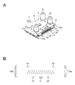
- FIG. 2 is a perspective view and a partially enlarged view of an embodiment of the present technology.
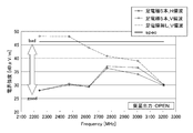
- FIG. 3 is a graph used to describe an embodiment of the present technology.
- FIG. 4 is a graph used to describe an embodiment of the present technology.
- FIG. 5 is a perspective view used for explaining the internal structure of an embodiment of the present technology.
- FIG. 6 is a diagram showing the passing characteristic of the interference wave to the signal terminal in the conventional model.
- FIG. 7 is a diagram illustrating a passing characteristic of the interference wave to the signal terminal according to the embodiment of the present technology.
- FIG. 8 is a diagram illustrating a passing characteristic of the interference wave to the signal terminal according to the embodiment of the present technology.
- FIG. 1 is a six-sided view of an embodiment of the present technology.
- FIG. 2 is a perspective view and a partially enlarged view of an embodiment of the present technology.
- FIG. 3 is a graph used to describe an embodiment
- FIG. 9 is a diagram illustrating a passing characteristic of the interference wave to the signal terminal according to the embodiment of the present technology.
- FIG. 10 is a diagram showing a frequency arrangement used for explanation of advanced BS broadcasting.
- FIG. 11 is a diagram for explaining overlapping of frequency bands.
- FIG. 10 shows the IF frequency in advanced BS broadcasting.
- the center frequency of the IF of channel number BS-1 is 1049.48 MHz.
- BS-3, BS-5, BS-7,. . . . . , BS-23 channels are arranged in order.
- the center frequency of IF of channel number BS-23 is 1471.44 MHz.
- the CS-IF is arranged in a frequency band higher than the IF of this BS.
- the center frequency of the IF of channel number ND-2 is 1613 MHz, and ND-2, ND-4, ND-6,. . . . .
- ND-24 channels are arranged in order.
- the center frequency of the IF of channel number ND-24 is 2053 MHz.
- the IFs of BS-1 to BS-23 and ND-2 to ND-24 are existing BS broadcast and CS broadcast channels, and the radio waves are right-handed circularly polarized waves.
- channel numbers BS-2, BS-4,. . . . , BS-24 and channel numbers ND-1, ND-3, ND-5,. . . . . , ND-23 channel is a left-handed circularly polarized channel.
- the center frequency of channel number BS-2 is 2241.66 MHz
- the center frequency of channel number BS-24BS is 2663.62 MHz
- the center frequency of channel number ND-1 is 2766 MHz
- the center frequency of channel number ND-23ND is 3206 MHz.
- FIG. 1 is a six-sided view of a tuner device.
- the tuner case is made of metal and has a box shape having a front surface 1, a back surface 2, an upper surface 3, a lower surface 4, a right side surface 5, and a left side surface 6.
- Four connectors 7, 8, 9, and 10 are provided on one of the front surface 1 and the back surface 2, for example, the front surface 1.
- These connectors 7 to 10 are provided in regions near the four corners of the front surface 1, respectively.
- the width in the height direction of the tuner case (the distance between the upper surface 3 and the lower surface 4) is set to be slightly smaller than the width of the rear panel of a device such as a recorder. It is made so that no useless space is generated on the upper side or the lower side of the apparatus.
- the tuner case may be rotated 90 degrees and attached to a device such as a recorder. In that case, the relationship between the top and bottom and the left and right is switched.
- Connectors 7 to 10 are coaxial connectors, for example, F-type connectors.
- F-type connector is connected to one end of a coaxial cable and is called an F-type connector plug or the like.
- Another type is an F-type connector that receives a central conductor (hereinafter referred to as a core wire) of a coaxial cable protruding from an F-type connector plug, and is called an F-type connector receptacle or the like.
- the connectors 7 to 10 are F-type connector receptacles.
- a configuration other than the F-type connector for example, an IEC (International Electrotechnical Commission) connector may be used.
- a plurality of signal transmission connection pins 11 are provided on one of the upper surface 3 and the lower surface 4 of the tuner case, for example, the lower surface 4.
- Mounting electrodes 12 a and 12 b protrude from the left and right ends of the lower surface 4.
- the mounting electrodes 12a and 12b are grounded electrodes.
- a tuner device according to an embodiment of the present technology is applied to, for example, a Blu-ray Disc (registered trademark) recorder (hereinafter simply referred to as a recorder as appropriate), a hard disk recorder, or an STB (Set-Top Box).
- the tuner device is mounted so that the rear panel and the front surface 1 of the tuner device are substantially parallel so that the connectors 7 to 10 protrude from the rear panel of the recorder.
- the connection pins 11 on the lower surface 4 of the tuner device are connected to the circuit board in the recorder.
- the mounting electrodes 12a and 12b are coupled to this circuit board.
- the IF is formed by frequency conversion by a converter received by the BS receiving antenna.
- the IF is supplied to the connector of the tuner device via a coaxial cable as a connection cable.
- a reception signal of terrestrial digital broadcasting is input to the connector 7, and an RF signal of terrestrial digital broadcasting is output from the connector 8.
- a satellite broadcast IF is input to the connector 9, and a satellite broadcast IF is output from the connector 10.
- Output signals from connectors 8 and 10 are supplied to the recorder.
- the configuration of the tuner device described above has an advantage that the thickness can be reduced when it is attached to a device such as a recorder, for example, compared to a tuner device having a configuration in which a connector is provided on the upper surface 3 instead of the front surface 1.
- a device such as a recorder
- the connection pin 11 since the distance between the connectors 9 and 10 and the connection pin 11 is reduced, for example, IF leaked from the vicinity of the connector may be radiated using the connection pin 11 as an antenna, and radio wave leakage may increase.
- radio wave leakage is suppressed by providing at least one foot electrode that is grounded in the vicinity of the connection pin 11.
- a plurality of, for example, five foot electrodes t1, t2, t3, t4, and t5 are provided so as to surround the outer periphery of the installation region (for example, a substantially band-like region) of the connection pin 11.
- the leg electrodes t1, t2, and t3 protrude from the front surface 1 of the tuner case (grounded) and are electrically and mechanically connected to the front surface 1.
- the leg electrodes t4 and t5 protrude from the lower surface 4 and are electrically and mechanically connected to the lower surface 4.
- the foot electrodes t1 to t5 are soldered to a ground pattern on a wiring board such as a recorder. By providing these foot electrodes t1 to t5, for example, it is possible to prevent IF leaked from the vicinity of the connector from flowing to the ground through the foot electrodes t1 to t5 and being radiated to the outside.
- radio waves in a band overlapping with IF from the outside can be sent to the ground, so that reception disturbance caused by external radio waves can be prevented.
- the upper side of FIG. 2B is the signal line arrangement side to the rear-stage television receiving circuit, and the lower side is the arrangement side of the connectors 7-10. Since the signal lines from each connection pin to the rear-stage television receiving circuit are arranged on the substrate on the signal line arrangement side to the rear-stage television receiving circuit, in the vicinity of the connection pins 11 (that is, the signal line arrangement portion). Can not place the foot electrode.
- FIG. 3 shows the measurement result of IF leakage of the advanced BS broadcast according to the above-described embodiment, for example, the result of measurement by a predetermined method defined by legal regulations.
- the horizontal axis indicates the frequency
- the vertical axis indicates the electric field strength.
- the horizontal line parallel to the frequency axis is a standard defined by legal regulations.
- the V polarization exceeds an acceptable standard.
- both the measured H-polarized light and V-polarized light can be less than the acceptable standard.
- FIG. 4 shows the confirmation result of the Wi-Fi (registered trademark) disturbance characteristics.
- the horizontal axis is the frequency, and the vertical axis is the minimum sensitivity deterioration amount. Since the minimum sensitivity represents the minimum radio wave that can be received, a large amount of minimum sensitivity deterioration means a decrease in reception performance.
- the reception performance is the lowest when no foot electrode is provided. Also, the reception performance can be improved by providing only one foot electrode. Furthermore, the reception performance can be increased as the number of leg electrodes is increased to 3, 4, and 5. For example, when one foot electrode is provided, the effect of preventing leakage and interference resistance can be enhanced by providing it at the center portion on the wide side of the connection pin 11.
- the foot electrode t1 is preferably at the center position of the attachment electrodes 12a and 12b. In the case where three foot electrodes are provided, it is effective to arrange the foot electrodes so as to surround the periphery of the connection pin 11 with a predetermined interval.
- the foot electrodes t1, t4 and t5 correspond to it.
- two foot electrodes are arranged in the vicinity of the foot electrode t1, t2 or t3 in FIG. 2B, and in addition, two foot electrodes t4 and t5 are arranged. .
- the position of the foot electrode on the connector arrangement side can be other than the position shown in the figure.
- FIG. 5 is a perspective view showing the internal structure with the circuit board and the lid removed.
- Shielding brackets 21a and 21b are attached to the inside of the front surface 1 of the tuner case.
- the four connectors 7 to 10 are attached using attachment holes provided in the vicinity of the four corners of the front surface 1.
- caulking or the like can be used as a method of attaching the connector.
- the external conductors of these connectors are made of metal such as iron, brass, and zinc, and are mechanically and electrically connected to the tuner case.
- These connection pieces 22 to 25 are respectively connected to a signal power feeding unit on a circuit board (not shown).
- a large number of interface connection pins 11 for transmitting and receiving data, signals and the like to and from an external circuit are planted on the lower surface 4.
- the connection pin 11 is attached to a circuit board of a device in which the tuner device is incorporated, for example, a recorder.
- the brackets 21a and 21b are formed by bending a metal plate having a shielding effect, for example, and have the same shape.
- the brackets 21a and 21b which are separate parts from the tuner case, are provided for shielding. If the tuner case is processed into a shielding shape, a gap is generated in the tuner case, and the shielding effect of the tuner case is impaired. This is to avoid it.
- the brackets 21a and 21b have connecting portions 26a and 26b and shield portions 27a, 27b, 28a and 28b formed at both ends of the connecting portions 26a and 26b, respectively.
- the shield portions 27a, 27b, 28a and 28b have first and second plate-like members joined at one end face, and the other end faces of the first and second plate-like members serve as corners of the tuner case. It joins to the inner surface of the nearby peripheral member.
- the shield part 27 a surrounds the connection piece 22 of the connector 7, and the shield part 27 b surrounds the connection piece 23 of the connector 8.
- the shield portion 28 a surrounds the connection piece 24 of the connector 9, and the shield portion 28 b surrounds the connection piece 25 of the connector 10. Therefore, the electromagnetic waves radiated from each connection piece can be shielded.
- the places where shield measures are required are the area of the connection piece 22 where the advanced BS broadcast IF is input and the area of the connection piece 23 where the advanced BS broadcast IF is output.
- the necessity of shielding the area of the connection pieces 24 and 25 for terrestrial digital broadcasting is low.
- the position to which the connector for advanced BS broadcasting is connected is fixed, inconvenience occurs when the tuner case is rotated or when the specifications differ depending on the manufacturer. Therefore, versatility can be improved by taking shield measures for all connector positions.
- the shape of the shield brackets 21a and 21b is merely an example, and various other shapes are possible. For example, four brackets may be used so as to separately surround four corners.
- FIG. 6 shows the pass characteristic of the interference wave related to the conventional tuner device that does not take a shield measure
- FIG. 7 shows the pass characteristic of the interferer wave of the tuner device that is shielded by the present technology. From these measurement results, it can be seen that according to the present technology, characteristic improvement of about 25 dB can be expected, and the shielding property can be enhanced.
- connection pin 11 contributes to interference wave radiation as an antenna.
- a small-capacitance capacitor that is effective in the frequency band of advanced BS broadcasting and has little influence on each signal line and power supply line is inserted into the connection pin 11 as a bypass capacitor. With this measure, it is possible to further improve the interference wave resistance.
- Fig. 8 shows the passage characteristics of the interference wave after connecting the bypass capacitors. As can be seen from FIG. 8, as a result of implementing this measure, an improvement effect of about 33 dB was confirmed from the conventional characteristics shown in FIG.
- connection pin 11 when there is no space for providing a bypass capacitor with respect to the connection pin 11, it is preferable to set the connectors in the two areas that are separated from the connection pin 11 as the input terminal and output terminal for BS broadcasting.
- FIG. 9 shows the passage characteristics of the interference wave when a connector at a position away from the connection pin 11 is used.
- FIG. 9 shows the passage characteristic of the interference wave of the connection piece 23. As can be seen from FIG. 9, an improvement effect of about 28 dB was confirmed from the conventional characteristic shown in FIG.
- this technique can also take the following structures.
- a box-shaped metal tuner case A plurality of connectors attached to one surface of the tuner case; A plurality of signal transmission connection pins provided on the other surface of the tuner case; A tuner device comprising: at least one foot electrode provided in the vicinity of the connection pin and grounded.
- the tuner case has a front surface, a back surface, an upper surface, a lower surface, a left side surface and a right side surface, A plurality of connectors are provided on one of the front surface and the back surface, The tuner device according to (1) or (2), wherein the connection pin and the foot electrode are provided on one of the upper surface and the lower surface. (4) Four connectors are respectively attached to areas near the four corners on one side of the tuner case, The tuner device according to any one of (1) to (3), wherein shield portions separate from the tuner case are provided in regions near the four corners inside the tuner case.
- the shield part has first and second plate-like members in which one end faces are joined together, The tuner device according to (4), wherein the other end surfaces of the first and second plate-like members are respectively joined to the inner surface of the peripheral surface member near the corner of the tuner case.
- Satellite digital broadcast reception signals are transmitted through the plurality of connectors, The tuner device according to any one of (1) to (5), wherein an IF signal of satellite digital broadcasting is transmitted through the connection pin.
Landscapes
- Engineering & Computer Science (AREA)
- Signal Processing (AREA)
- Multimedia (AREA)
- Microelectronics & Electronic Packaging (AREA)
- Physics & Mathematics (AREA)
- Astronomy & Astrophysics (AREA)
- General Physics & Mathematics (AREA)
- Computer Networks & Wireless Communication (AREA)
- Structure Of Receivers (AREA)
- Shielding Devices Or Components To Electric Or Magnetic Fields (AREA)
Abstract
箱状の金属製のチューナケースと、チューナケースの一面に取り付けられた複数のコネクタと、チューナケースの他の面に設けられている複数の信号伝送用の接続ピンと、接続ピンの近傍に設けられ、接地されている少なくとも1本の足電極とを備えるチューナ装置である。
Description
本技術は、高度広帯域衛星デジタル放送の受信のために使用されるチューナ装置に関する。
現在の衛星デジタルテレビジョン放送では、約1GHz~2.1GHzまでの中間周波数(IF(Intermediate Frequency)と適宜称する。また、IFは、中間周波数又は中間周波数信号の両者を表す語句として使用する。)にてテレビジョン信号を伝送している。ただし、2018年に実用放送が予定されている高度広帯域衛星デジタル放送(高度BS放送と適宜称する)は、4K/8Kの超高精細度テレビジョン放送を提供するために、IFが約2.1GHz~3.2GHzまで拡張される。
このような周波数帯の拡大によって、他の無線システム(Wi-Fi(登録商標))との相互干渉が懸念されている。例えば漏洩IF信号の妨害によって、Wi-Fi(登録商標)のデータ伝送速度が遅くなるようなおそれが生じる。また、電子レンジなどの日常生活で使用されている機器の電波が高度BS放送の受信設備に入り込み、受信障害が発生するおそれがあった。このような状況のもとで、衛星放送用受信設備からの電波漏洩等に関する次のような技術基準を定める法律が施行された(参照 非特許文献1)。
周波数:2224.41~3223.25 MHz
漏洩基準(副次的に発生する電波漏洩の限度):-49.1 dBm以下
(3m離れて46.2 dBμV/m以下)
帯域幅:33.7561 MHzあたり
漏洩基準(副次的に発生する電波漏洩の限度):-49.1 dBm以下
(3m離れて46.2 dBμV/m以下)
帯域幅:33.7561 MHzあたり
総務省令第76号 無線設備規則の一部を改正(第24条)
BS放送を受信するための既存のチューナ装置では、上述した法律に規定されている電波漏洩に関する基準をクリアすることが困難であった。
したがって、本技術の目的は、電波漏洩をより減少させることができる高度BS放送を受信するためのチューナ装置を提供することにある。
本技術は、箱状の金属製のチューナケースと、
チューナケースの一面に取り付けられた複数のコネクタと、
チューナケースの他の面に設けられている複数の信号伝送用の接続ピンと、
接続ピンの近傍に設けられ、接地されている少なくとも1本の足電極と
を備えるチューナ装置である。
チューナケースの一面に取り付けられた複数のコネクタと、
チューナケースの他の面に設けられている複数の信号伝送用の接続ピンと、
接続ピンの近傍に設けられ、接地されている少なくとも1本の足電極と
を備えるチューナ装置である。
少なくとも一つの実施形態によれば、チューナ装置からの電波漏洩をより少ないものとできる。なお、ここに記載された効果は必ずしも限定されるものではなく、本技術中に記載されたいずれかの効果又はそれらと異質な効果であっても良い。また、以下の説明における例示された効果により本技術の内容が限定して解釈されるものではない。
以下に説明する実施形態は、本技術の好適な具体例であり、技術的に好ましい種々の限定が付されている。しかしながら、本技術の範囲は、以下の説明において、特に本技術を限定する旨の記載がない限り、これらの実施形態に限定されないものとする。
なお、本技術の説明は、下記の順序にしたがってなされる。
<1.高度BS放送における問題点>
<2.本技術の一実施形態>
<3.変形例>
なお、本技術の説明は、下記の順序にしたがってなされる。
<1.高度BS放送における問題点>
<2.本技術の一実施形態>
<3.変形例>
<1.高度BS放送における問題点>
図10及び図11を参照して高度BS放送における問題点について説明する。図10は、高度BS放送におけるIFの周波数を示している。例えばチャンネル番号BS-1のIFの中心周波数が1049.48MHzである。BS-3,BS-5,BS-7,.....,BS-23 のチャンネルが順に配置されている。チャンネル番号BS-23 のIFの中心周波数が1471.44MHzである。このBSのIFより高い周波数帯域に、CS-IFが配置されている。例えばチャンネル番号ND-2のIFの中心周波数が1613MHzであり、ND-2,ND-4,ND-6,.....,ND-24 のチャンネルが順に配置されている。例えばチャンネル番号ND-24 のIFの中心周波数が2053MHzである。これらのBS-1~BS-23 及びND-2~ND-24 のIFは、既存のBS放送及びCS放送のチャンネルであり、電波が右旋円偏波である。
図10及び図11を参照して高度BS放送における問題点について説明する。図10は、高度BS放送におけるIFの周波数を示している。例えばチャンネル番号BS-1のIFの中心周波数が1049.48MHzである。BS-3,BS-5,BS-7,.....,BS-23 のチャンネルが順に配置されている。チャンネル番号BS-23 のIFの中心周波数が1471.44MHzである。このBSのIFより高い周波数帯域に、CS-IFが配置されている。例えばチャンネル番号ND-2のIFの中心周波数が1613MHzであり、ND-2,ND-4,ND-6,.....,ND-24 のチャンネルが順に配置されている。例えばチャンネル番号ND-24 のIFの中心周波数が2053MHzである。これらのBS-1~BS-23 及びND-2~ND-24 のIFは、既存のBS放送及びCS放送のチャンネルであり、電波が右旋円偏波である。
高度BS放送では、左旋円偏波が使用される。すなわち、チャンネル番号BS-2,BS-4,....,BS-24 並びにチャンネル番号ND-1,ND-3,ND-5,.....,ND-23 のチャンネルが左旋円偏波のチャンネルである。例えばチャンネル番号BS-2の中心周波数が2241.66MHzであり、チャンネル番号BS-24 の中心周波数が2663.62MHzである。また、チャンネル番号ND-1の中心周波数が2766MHzであり、チャンネル番号ND-23 の中心周波数が3206MHzである。
図11に示すように、チャンネル番号BS-12及びBS-14の周波数帯には、他の無線システム(Wi-Fi(登録商標))又は電子レンジ等の産業機器で発生した不要輻射による妨害電波が存在している。したがって、チューナ装置からこの周波数帯の電波漏洩は、他の無線システムに対して妨害を与えるので、抑える必要がある。また、妨害波がチューナ装置に影響して受信障害が発生するおそれがあるので、妨害波の影響を受けないようにする必要がある。
<2.本技術の一実施形態>
図1、図2及び図3を参照して本技術の一実施形態について説明する。図1は、チューナ装置の六面図である。チューナケースは、金属製のもので、前面1、背面2、上面3、下面4、右側面5、左側面6を有する箱状のものである。前面1及び背面2の一方例えば前面1に4個のコネクタ7,8,9,10が設けられている。これらのコネクタ7~10は、前面1の4個のコーナー近傍の領域にそれぞれ設けられている。
図1、図2及び図3を参照して本技術の一実施形態について説明する。図1は、チューナ装置の六面図である。チューナケースは、金属製のもので、前面1、背面2、上面3、下面4、右側面5、左側面6を有する箱状のものである。前面1及び背面2の一方例えば前面1に4個のコネクタ7,8,9,10が設けられている。これらのコネクタ7~10は、前面1の4個のコーナー近傍の領域にそれぞれ設けられている。
例えばチューナケースの高さ方向の幅(上面3及び下面4間の距離)がレコーダ等の機器の背面パネルの幅よりやや小さいものとされており、レコーダに取り付けた時に、レコーダのケース内でチューナ装置の上側又は下側に無駄なスペースが発生しないようになされる。なお、チューナケースは、90度回転させてレコーダ等の機器に対して取り付けるようにしてもよい。その場合は、上下と左右の関係が入れ替わったものとなる。
コネクタ7~10は、同軸コネクタであり、例えばF型コネクタである。F型コネクタの一つのタイプは、同軸ケーブルの一端に接続されるものであり、F型コネクタプラグ等と呼ばれる。他のタイプは、F型コネクタプラグから突出している同軸ケーブルの中心導体(以下、芯線と称する)を受け入れるF型コネクタであり、F型コネクタレセプタクル等と呼ばれる。コネクタ7~10は、F型コネクタレセプタクルである。但し、コネクタ7~10として、F型コネクタ以外の他の構成例えばIEC(International Electrotechnical Commission) コネクタを使用してもよい。
チューナケースの上面3及び下面4の一方例えば下面4に複数の信号伝送用の接続ピン11が設けられている。下面4の左右の両端には、取り付け用電極12a及び12bが突出されている。取り付け用電極12a及び12bは、接地された電極である。本技術の一実施形態によるチューナ装置は、例えばブルーレイディスク(登録商標)レコーダ(以下、単にレコーダと適宜称する)、ハードディスクレコーダ又はSTB(Set-Top Box)に適用されるものである。
例えばレコーダの背面パネルからコネクタ7~10が突出するように、背面パネルとチューナ装置の前面1がほぼ平行になるように、チューナ装置が取り付けられる。チューナ装置の下面4の接続ピン11がレコーダ内の回路基板と接続される。取り付け用電極12a及び12bは、この回路基板と結合される。
図示しないが、BS受信アンテナによって受信されたコンバータにて周波数変換されることによってIFが形成される。IFが接続ケーブルとしての同軸ケーブルを介してチューナ装置のコネクタに供給される。コネクタ7に対して例えば地上デジタル放送の受信信号が入力され、コネクタ8から地上デジタル放送のRF信号が出力される。また、コネクタ9に対して例えば衛星放送のIFが入力され、コネクタ10から衛星放送のIFが出力される。コネクタ8及び10からの出力信号がレコーダに対して供給される。
上述したチューナ装置の構成は、レコーダ等の機器に取り付ける場合、例えば前面1ではなく、上面3にコネクタを設ける構成のチューナ装置に比して厚みを薄くすることができる利点がある。その反面、コネクタ9,10と接続ピン11間の距離が近くなるために、例えばコネクタ付近から漏れたIFが接続ピン11をアンテナとして放射され、電波漏洩が多くなる可能性がある。
本技術の一実施形態では、接続ピン11の近傍に接地されている少なくとも1本の足電極を設けることによって電波漏洩を抑えるようにするものである。一実施形態では、接続ピン11の設置領域(例えばほぼ帯状の領域)の外周を取り囲むように、複数例えば5本の足電極t1,t2,t3,t4及びt5を設ける。
足電極t1,t2,t3は、チューナケース(接地されている)の前面1から突出され、前面1と電気的及び機械的に接続されている。足電極t4及びt5は、下面4から突出され、下面4と電気的及び機械的に接続されている。また、足電極t1~t5は、レコーダ等の配線基板上の接地パターンとはんだ付けされる。これらの足電極t1~t5を設けることによって、例えばコネクタ付近から漏れたIFが足電極t1~t5を通じて接地に流れ、外部に放射されることを防止することができる。また、外部からのIFと重なり合う帯域の電波を接地に流すことができ、外部の電波により与えられる受信障害を防止することができる。図2Bの上側が後段テレビジョン受信回路への信号ライン配置側であり、下側がコネクタ7~10の配置側である。後段テレビジョン受信回路への信号ライン配置側には各接続ピンから後段テレビジョン受信回路への信号ラインが基板上に配置されるので、接続ピン11の近傍(すなわち、信号ライン配置部)には、足電極を配置することができない。
図3は、上述した一実施形態の高度BS放送のIF漏洩の測定結果、例えば法律規則で定められている所定の方法で測定した場合の結果を示している。図3において横軸が周波数を示し、縦軸は、電界強度を示す。また、周波数軸と平行な横線は、法律規則で定められている基準である。足電極を設けないチューナ装置の場合では、V偏波が許容基準を上回っている周波数帯がある。一方、5本の足電極を設けた本技術の一実施形態では、測定されたH偏波及びV偏波の両者を許容基準以下とできる。
図4は、Wi-Fi(登録商標)妨害特性の確認結果を示している。横軸が周波数であり、縦軸が最小感度劣化量である。最小感度は、受信できる最小の電波を表しているので、最小感度劣化量が大きいことは、受信性能の低下を意味している。図4に示すように、足電極を設けない場合が最も受信性能が低い。また、足電極を1本設けるだけでも受信性能が改善される。さらに、足電極を3本、4本、5本と増やすにしたがって、受信性能を高くすることができる。例えば足電極を1本設ける場合は、接続ピン11の幅が広い側の中心部に設けることが漏洩防止や妨害耐性の効果が高くできる。図2Bの足電極t1がこれに該当する。さらに、足電極t1は、取り付け用電極12a及び12bの中心位置が好ましい。3本の足電極を設ける場合では、接続ピン11の周辺に対して一定間隔をあけて囲むように足電極を配置すると効果的である。図2Bにおいて、足電極t1、t4及びt5がそれにあたる。さらに、4本の足電極を設ける場合も同様に、図2Bにおける足電極t1、t2又はt3の付近に2本の足電極を配置し、加えてt4及びt5の2本の足電極を配置する。なお、コネクタ配置側の足電極の位置は、図示の位置以外が可能である。
図5は、回路基板及び蓋を取り外した状態の内部構造を示す斜視図である。チューナケースの前面1の内側に対して、シールド用のブラケット21a及び21bが取り付けられている。前面1の四隅の近傍にそれぞれ設けられた取り付け用の穴を使用して4個のコネクタ7~10が取り付けられる。コネクタの取り付け方法としては、カシメ等が使用できる。これらのコネクタの外部導体は、鉄、真鍮、亜鉛等の金属からなり、チューナケースと機械的及び電気的に接続される。
各コネクタに接続された同軸ケーブルの芯線(中心導体)と接続された接続片22、23、24、25がチューナケース内に突出している。これらの接続片22~25は、回路基板(図示しない)上の信号給電部に対してそれぞれ接続される。さらに、下面4に外部回路との間でデータ、信号等を送受するためのインターフェース用の接続ピン11が多数植立されている。接続ピン11は、チューナ装置が組み込まれる機器例えばレコーダの回路基板に対して取り付けられる。
ブラケット21a及び21bは、例えばシールド効果を有する金属板を折り曲げ加工したもので、互いに同一の形状を有する。チューナケースと別部品のブラケット21a及び21bをシールド用に設けるのは、若し、チューナケースをシールド用の形状に加工すると、チューナケースに隙間が発生し、チューナケースのシールド効果が損なわれることを回避するためである。
ブラケット21a及び21bは、連結部26a及び26bと、連結部26a及び26bのそれぞれの両端にそれぞれ形成されたシールド部27a、27b,28a及び28bを有する。シールド部27a、27b、28a及び28bは、一方の端面同士が接合された第1及び第2の板状部材を有し、第1及び第2の板状部材の他方の端面をチューナケースのコーナー近傍の周面部材の内面にそれぞれ接合する。
シールド部27aは、コネクタ7の接続片22の周囲を取り囲むものであり、シールド部27bは、コネクタ8の接続片23の周囲を取り囲むものである。シールド部28aは、コネクタ9の接続片24の周囲を取り囲むものであり、シールド部28bは、コネクタ10の接続片25の周囲を取り囲むものである。したがって、各接続片から放射される電磁波をシールドすることができる。
なお、シールド対策が必要とされる箇所は、高度BS放送のIFが入力される接続片22の領域、並びに高度BS放送のIFが出力される接続片23の領域である。地上デジタル放送用の接続片24及び25の領域をシールドする必要性が低い。しかしながら、高度BS放送用のコネクタを接続する位置を固定すると、チューナケースを回転させた場合や、メーカーによって異なる仕様に対応する場合などで、不都合が生じる。したがって、全てのコネクタの位置に対してシールド対策を施すことによって汎用性を向上させることができる。
なお、シールド用のブラケット21a及び21bの形状は、一例であって、他の形状が種々可能である。例えば4個のコーナーを別々に取り囲むように、4個に分離されたブラケットを使用してもよい。
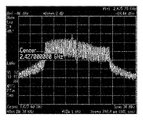
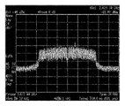
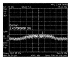
シールド効果の改善について図面を参照して説明する。一例として、中心周波数が2.427GHzで周波数範囲が約30MHzの新規追加周波数領域のIF信号をコネクタ7に入力し、コネクタ8からこのIF信号を出力する場合に、地上デジタル放送用のコネクタ10において上述の周波数の妨害波のレベルを測定する。
図6は、シールド対策を行っていない従来のチューナ装置に関する妨害波の通過特性を示し、図7は、本技術によりシールド対策がなされたチューナ装置の妨害波の通過特性を示す。これらの測定結果から本技術によれば、25dB程度の特性改善が見込まれ、遮蔽性を高めることができることが分かる。
さらに、シールド効果を高める構成について説明する。接続ピン11は、アンテナとして妨害波の輻射に寄与する。この接続ピン11の影響を抑えるために、高度BS放送の周波数帯域に効果があり、且つ各信号ラインや電源ラインへの影響の少ない容量の小さいコンデンサをパスコンとして接続ピン11に挿入する。この対策により、さらなる妨害波耐性改善を実現できる。
図8は、パスコンを接続した後の妨害波の通過特性を表している。図8から分かるように、この対策を実施した結果、図6に示す従来の特性より33dB程度の改善効果が確認できた。
また、接続ピン11に対してパスコンを設けるスペースがない場合には、接続ピン11との距離が離れている二つの領域のコネクタをBS放送用の入力端子及び出力端子に設定することが好ましい。
この接続ピン11と離れた位置のコネクタを使用した場合の妨害波の通過特性を図9に示す。図9は接続片23の妨害波の通過特性を示しており、図9から分かるように、図6に示す従来の特性より28dB程度の改善効果が確認できた。
上述した本技術によって、高度BS放送(4K/8K放送)に対応した新規追加周波数領域(2.1GHz~3.2GHz)のIFによって発生する種々の妨害波からの干渉や輻射に関しても、遮蔽効果の優れたチューナ装置を構成することができる。さらに、チューナケースのコーナーにそれぞれコネクタを設け、各コネクタに対してシールド対策を行うことによって、高度BS放送の新規追加周波数領域のIFを扱うコネクタを自由に設定することができ、汎用性が優れた構成とできる。
<3.変形例>
以上、本技術の実施形態について具体的に説明したが、上述の各実施形態に限定されるものではなく、本技術の技術的思想に基づく各種の変形が可能である。例えば足電極t1~t5は、チューナケース内部のブラケットから突出させるようにしてもよい。また、上述の実施形態の構成、方法、工程、形状、材料および数値などは、本技術の主旨を逸脱しない限り、互いに組み合わせることが可能である。
以上、本技術の実施形態について具体的に説明したが、上述の各実施形態に限定されるものではなく、本技術の技術的思想に基づく各種の変形が可能である。例えば足電極t1~t5は、チューナケース内部のブラケットから突出させるようにしてもよい。また、上述の実施形態の構成、方法、工程、形状、材料および数値などは、本技術の主旨を逸脱しない限り、互いに組み合わせることが可能である。
なお、本技術は、以下のような構成も取ることができる。
(1)
箱状の金属製のチューナケースと、
前記チューナケースの一面に取り付けられた複数のコネクタと、
前記チューナケースの他の面に設けられている複数の信号伝送用の接続ピンと、
前記接続ピンの近傍に設けられ、接地されている少なくとも1本の足電極と
を備えるチューナ装置。
(2)
前記接続ピンの設置領域を取り囲むように、複数の前記足電極を設けた(1)に記載のチューナ装置。
(3)
前記チューナケースは、前面、背面、上面、下面、左側面及び右側面を有し、
前記前面及び前記背面の一方に複数のコネクタが設けられ、
前記上面及び下面の一方に前記接続ピン及び前記足電極が設けられた(1)又は(2)に記載のチューナ装置。
(4)
前記チューナケースの一面の4個のコーナー近傍の領域にそれぞれ4個のコネクタが取り付けられ、
前記チューナケースと別個のシールド部を前記チューナケースの内側の前記4個のコーナー近傍の領域にそれぞれ設けるようにした(1)から(3)のいずれかに記載のチューナ装置。
(5)
前記シールド部は、一方の端面同士が接合された第1及び第2の板状部材を有し、
前記第1及び第2の板状部材の他方の端面を前記チューナケースのコーナー近傍の前記周面部材の内面にそれぞれ接合するようにした(4)に記載のチューナ装置。
(6)
衛星デジタル放送の受信信号が複数の前記コネクタを通じて伝送され、
衛星デジタル放送のIF信号が前記接続ピンを通じて伝送される(1)から(5)のいずれかに記載のチューナ装置。
(7)
前記衛星デジタル放送が高度BS放送である(6)に記載のチューナ装置。
(1)
箱状の金属製のチューナケースと、
前記チューナケースの一面に取り付けられた複数のコネクタと、
前記チューナケースの他の面に設けられている複数の信号伝送用の接続ピンと、
前記接続ピンの近傍に設けられ、接地されている少なくとも1本の足電極と
を備えるチューナ装置。
(2)
前記接続ピンの設置領域を取り囲むように、複数の前記足電極を設けた(1)に記載のチューナ装置。
(3)
前記チューナケースは、前面、背面、上面、下面、左側面及び右側面を有し、
前記前面及び前記背面の一方に複数のコネクタが設けられ、
前記上面及び下面の一方に前記接続ピン及び前記足電極が設けられた(1)又は(2)に記載のチューナ装置。
(4)
前記チューナケースの一面の4個のコーナー近傍の領域にそれぞれ4個のコネクタが取り付けられ、
前記チューナケースと別個のシールド部を前記チューナケースの内側の前記4個のコーナー近傍の領域にそれぞれ設けるようにした(1)から(3)のいずれかに記載のチューナ装置。
(5)
前記シールド部は、一方の端面同士が接合された第1及び第2の板状部材を有し、
前記第1及び第2の板状部材の他方の端面を前記チューナケースのコーナー近傍の前記周面部材の内面にそれぞれ接合するようにした(4)に記載のチューナ装置。
(6)
衛星デジタル放送の受信信号が複数の前記コネクタを通じて伝送され、
衛星デジタル放送のIF信号が前記接続ピンを通じて伝送される(1)から(5)のいずれかに記載のチューナ装置。
(7)
前記衛星デジタル放送が高度BS放送である(6)に記載のチューナ装置。
1・・・前面、2・・・背面、3・・・上面、4・・・下面、5・・・右側面、
6・・・左側面、7,8,9,10・・・コネクタ、11・・・接続ピン、
t1~t5・・・足電極、21a,21b・・・ブラケット、
27a,27b,28a,28b・・・シールド部
6・・・左側面、7,8,9,10・・・コネクタ、11・・・接続ピン、
t1~t5・・・足電極、21a,21b・・・ブラケット、
27a,27b,28a,28b・・・シールド部
Claims (7)
- 箱状の金属製のチューナケースと、
前記チューナケースの一面に取り付けられた複数のコネクタと、
前記チューナケースの他の面に設けられている複数の信号伝送用の接続ピンと、
前記接続ピンの近傍に設けられ、接地されている少なくとも1本の足電極と
を備えるチューナ装置。 - 前記接続ピンの設置領域を取り囲むように、複数の前記足電極を設けた請求項1に記載のチューナ装置。
- 前記チューナケースは、前面、背面、上面、下面、左側面及び右側面を有し、
前記前面及び前記背面の一方に複数のコネクタが設けられ、
前記上面及び下面の一方に前記接続ピン及び前記足電極が設けられた請求項1に記載のチューナ装置。 - 前記チューナケースの一面の4個のコーナー近傍の領域にそれぞれ4個のコネクタが取り付けられ、
前記チューナケースと別個のシールド部を前記チューナケースの内側の前記4個のコーナー近傍の領域にそれぞれ設けるようにした請求項1に記載のチューナ装置。 - 前記シールド部は、一方の端面同士が接合された第1及び第2の板状部材を有し、
前記第1及び第2の板状部材の他方の端面を前記チューナケースのコーナー近傍の前記周面部材の内面にそれぞれ接合するようにした請求項4に記載のチューナ装置。 - 衛星デジタル放送の受信信号が複数の前記コネクタを通じて伝送され、
衛星デジタル放送のIF信号が前記接続ピンを通じて伝送される請求項1に記載のチューナ装置。 - 前記衛星デジタル放送が高度BS放送である請求項6に記載のチューナ装置。
Priority Applications (3)
| Application Number | Priority Date | Filing Date | Title |
|---|---|---|---|
| CN201980030857.9A CN112088493B (zh) | 2018-05-07 | 2019-03-20 | 调谐器装置 |
| KR1020207030770A KR20210003762A (ko) | 2018-05-07 | 2019-03-20 | 튜너 장치 |
| US17/052,024 US11470378B2 (en) | 2018-05-07 | 2019-03-20 | Tuner device |
Applications Claiming Priority (2)
| Application Number | Priority Date | Filing Date | Title |
|---|---|---|---|
| JP2018-089265 | 2018-05-07 | ||
| JP2018089265A JP2019197943A (ja) | 2018-05-07 | 2018-05-07 | チューナ装置 |
Publications (1)
| Publication Number | Publication Date |
|---|---|
| WO2019216030A1 true WO2019216030A1 (ja) | 2019-11-14 |
Family
ID=68466826
Family Applications (1)
| Application Number | Title | Priority Date | Filing Date |
|---|---|---|---|
| PCT/JP2019/011629 Ceased WO2019216030A1 (ja) | 2018-05-07 | 2019-03-20 | チューナ装置 |
Country Status (5)
| Country | Link |
|---|---|
| US (1) | US11470378B2 (ja) |
| JP (1) | JP2019197943A (ja) |
| KR (1) | KR20210003762A (ja) |
| CN (1) | CN112088493B (ja) |
| WO (1) | WO2019216030A1 (ja) |
Families Citing this family (1)
| Publication number | Priority date | Publication date | Assignee | Title |
|---|---|---|---|---|
| KR102861487B1 (ko) * | 2020-08-04 | 2025-09-18 | 엘지이노텍 주식회사 | 튜너 모듈 |
Citations (2)
| Publication number | Priority date | Publication date | Assignee | Title |
|---|---|---|---|---|
| JP2003234971A (ja) * | 2002-02-08 | 2003-08-22 | Alps Electric Co Ltd | チューナ用集積回路 |
| JP2012156690A (ja) * | 2011-01-25 | 2012-08-16 | Sharp Corp | 受信モジュール |
Family Cites Families (11)
| Publication number | Priority date | Publication date | Assignee | Title |
|---|---|---|---|---|
| US3987263A (en) * | 1973-12-12 | 1976-10-19 | Matsushita Electric Industrial Co., Ltd. | Switching device for switching signals of very high and ultrahigh frequencies |
| JP3533033B2 (ja) | 1996-04-10 | 2004-05-31 | 松下電器産業株式会社 | 高周波装置 |
| JP2000286022A (ja) | 1999-03-31 | 2000-10-13 | Sharp Corp | 電子機器用端子コネクタ及び電子機器 |
| DE202005020107U1 (de) * | 2005-12-23 | 2007-02-15 | Kathrein-Werke Kg | An einer Leiterplatine elektrisch angeschlossene koaxiale H-Steckverbindungs-Einrichtung sowie zugehörige Steckverbindereinheit |
| JP4246224B2 (ja) | 2006-09-01 | 2009-04-02 | シャープ株式会社 | 放送受信装置 |
| JP4725737B2 (ja) * | 2006-09-20 | 2011-07-13 | ミツミ電機株式会社 | チューナ装置 |
| JP2010206680A (ja) * | 2009-03-05 | 2010-09-16 | Sharp Corp | チューナユニット |
| JP5828764B2 (ja) | 2009-07-13 | 2015-12-09 | ソニー株式会社 | 受信装置 |
| JP2011139321A (ja) * | 2009-12-28 | 2011-07-14 | Sony Corp | チューナモジュールおよび受信装置 |
| JP2011176096A (ja) * | 2010-02-24 | 2011-09-08 | Mitsumi Electric Co Ltd | 電子機器 |
| JP2013042311A (ja) | 2011-08-12 | 2013-02-28 | Sony Corp | チューナモジュール、回路基板、及び回路基板の組立方法 |
-
2018
- 2018-05-07 JP JP2018089265A patent/JP2019197943A/ja active Pending
-
2019
- 2019-03-20 WO PCT/JP2019/011629 patent/WO2019216030A1/ja not_active Ceased
- 2019-03-20 US US17/052,024 patent/US11470378B2/en active Active
- 2019-03-20 KR KR1020207030770A patent/KR20210003762A/ko active Pending
- 2019-03-20 CN CN201980030857.9A patent/CN112088493B/zh active Active
Patent Citations (2)
| Publication number | Priority date | Publication date | Assignee | Title |
|---|---|---|---|---|
| JP2003234971A (ja) * | 2002-02-08 | 2003-08-22 | Alps Electric Co Ltd | チューナ用集積回路 |
| JP2012156690A (ja) * | 2011-01-25 | 2012-08-16 | Sharp Corp | 受信モジュール |
Non-Patent Citations (2)
| Title |
|---|
| ANONYMOUS: "Sony Commercializes the Industry's First *1 ISDB-S3 Compatible Demodula Tuner Modules for 4K and 8K Satellite Digital Broadcasts", 27 July 2016 (2016-07-27), pages 1 - 3, XP055651222, Retrieved from the Internet <URL:https://www.sony.net/SonyInfo/News/Press/201607/16-069E/index.html> * |
| TAKESHI USAMI: "Outline of 4K Test Broadcast by left-hand Circular Polarization", BROADCAST ENGINEERING, vol. 70, 01-09-2017, pages 60 - 64 * |
Also Published As
| Publication number | Publication date |
|---|---|
| US20210235146A1 (en) | 2021-07-29 |
| KR20210003762A (ko) | 2021-01-12 |
| CN112088493A (zh) | 2020-12-15 |
| JP2019197943A (ja) | 2019-11-14 |
| US11470378B2 (en) | 2022-10-11 |
| CN112088493B (zh) | 2022-12-06 |
Similar Documents
| Publication | Publication Date | Title |
|---|---|---|
| US9661791B2 (en) | RF interference suppressor | |
| US10644670B2 (en) | Radiofrequency filter with improved attenuation of common mode signals | |
| US20130266275A1 (en) | Coaxial connector with ingress reduction shield | |
| US11470378B2 (en) | Tuner device | |
| US11265026B2 (en) | Tuner device | |
| US20130187823A1 (en) | Isolation of antennas mounted on a printed circuit board | |
| JP7443079B2 (ja) | 光端末装置 | |
| CN110943305B (zh) | 一种用于无线测试的屏蔽设备 | |
| JP6618323B2 (ja) | 電子機器ケース | |
| TWI681600B (zh) | 連接器模組與機上盒 | |
| JPS6325798Y2 (ja) | ||
| JP6869603B2 (ja) | 電子機器ケース | |
| KR970006762B1 (ko) | 안테나 시일드 박스 | |
| KR200426354Y1 (ko) | 인접 공중파 전자 간섭 감쇄 장치 | |
| CN203590347U (zh) | 电视机高频头组件 | |
| JP2006054829A (ja) | Tv受像機、記録再生装置及びチューナ | |
| Goncharsky | The EMC problems facing amateur radio community in the post communist soviet republics and their effect on the future growth of the amateur radio population | |
| TWM577500U (zh) | Passive component signal measurement system | |
| JPH0644718B2 (ja) | 電波障害防止装置 | |
| KR20160060309A (ko) | 방송 수신 장치 |
Legal Events
| Date | Code | Title | Description |
|---|---|---|---|
| 121 | Ep: the epo has been informed by wipo that ep was designated in this application |
Ref document number: 19800883 Country of ref document: EP Kind code of ref document: A1 |
|
| ENP | Entry into the national phase |
Ref document number: 20207030770 Country of ref document: KR Kind code of ref document: A |
|
| NENP | Non-entry into the national phase |
Ref country code: DE |
|
| 122 | Ep: pct application non-entry in european phase |
Ref document number: 19800883 Country of ref document: EP Kind code of ref document: A1 |