WO2019198331A1 - 車両用電子キーシステム - Google Patents
車両用電子キーシステム Download PDFInfo
- Publication number
- WO2019198331A1 WO2019198331A1 PCT/JP2019/005331 JP2019005331W WO2019198331A1 WO 2019198331 A1 WO2019198331 A1 WO 2019198331A1 JP 2019005331 W JP2019005331 W JP 2019005331W WO 2019198331 A1 WO2019198331 A1 WO 2019198331A1
- Authority
- WO
- WIPO (PCT)
- Prior art keywords
- vehicle
- distance
- communication devices
- communication device
- signal
- Prior art date
Links
Images

Classifications
-
- B—PERFORMING OPERATIONS; TRANSPORTING
- B60—VEHICLES IN GENERAL
- B60R—VEHICLES, VEHICLE FITTINGS, OR VEHICLE PARTS, NOT OTHERWISE PROVIDED FOR
- B60R25/00—Fittings or systems for preventing or indicating unauthorised use or theft of vehicles
- B60R25/20—Means to switch the anti-theft system on or off
- B60R25/24—Means to switch the anti-theft system on or off using electronic identifiers containing a code not memorised by the user
- B60R25/245—Means to switch the anti-theft system on or off using electronic identifiers containing a code not memorised by the user where the antenna reception area plays a role
-
- G—PHYSICS
- G01—MEASURING; TESTING
- G01S—RADIO DIRECTION-FINDING; RADIO NAVIGATION; DETERMINING DISTANCE OR VELOCITY BY USE OF RADIO WAVES; LOCATING OR PRESENCE-DETECTING BY USE OF THE REFLECTION OR RERADIATION OF RADIO WAVES; ANALOGOUS ARRANGEMENTS USING OTHER WAVES
- G01S13/00—Systems using the reflection or reradiation of radio waves, e.g. radar systems; Analogous systems using reflection or reradiation of waves whose nature or wavelength is irrelevant or unspecified
- G01S13/74—Systems using reradiation of radio waves, e.g. secondary radar systems; Analogous systems
- G01S13/76—Systems using reradiation of radio waves, e.g. secondary radar systems; Analogous systems wherein pulse-type signals are transmitted
- G01S13/765—Systems using reradiation of radio waves, e.g. secondary radar systems; Analogous systems wherein pulse-type signals are transmitted with exchange of information between interrogator and responder
-
- E—FIXED CONSTRUCTIONS
- E05—LOCKS; KEYS; WINDOW OR DOOR FITTINGS; SAFES
- E05B—LOCKS; ACCESSORIES THEREFOR; HANDCUFFS
- E05B81/00—Power-actuated vehicle locks
- E05B81/54—Electrical circuits
- E05B81/64—Monitoring or sensing, e.g. by using switches or sensors
- E05B81/76—Detection of handle operation; Detection of a user approaching a handle; Electrical switching actions performed by door handles
- E05B81/78—Detection of handle operation; Detection of a user approaching a handle; Electrical switching actions performed by door handles as part of a hands-free locking or unlocking operation
-
- G—PHYSICS
- G01—MEASURING; TESTING
- G01S—RADIO DIRECTION-FINDING; RADIO NAVIGATION; DETERMINING DISTANCE OR VELOCITY BY USE OF RADIO WAVES; LOCATING OR PRESENCE-DETECTING BY USE OF THE REFLECTION OR RERADIATION OF RADIO WAVES; ANALOGOUS ARRANGEMENTS USING OTHER WAVES
- G01S13/00—Systems using the reflection or reradiation of radio waves, e.g. radar systems; Analogous systems using reflection or reradiation of waves whose nature or wavelength is irrelevant or unspecified
- G01S13/02—Systems using reflection of radio waves, e.g. primary radar systems; Analogous systems
- G01S13/0209—Systems with very large relative bandwidth, i.e. larger than 10 %, e.g. baseband, pulse, carrier-free, ultrawideband
-
- G—PHYSICS
- G01—MEASURING; TESTING
- G01S—RADIO DIRECTION-FINDING; RADIO NAVIGATION; DETERMINING DISTANCE OR VELOCITY BY USE OF RADIO WAVES; LOCATING OR PRESENCE-DETECTING BY USE OF THE REFLECTION OR RERADIATION OF RADIO WAVES; ANALOGOUS ARRANGEMENTS USING OTHER WAVES
- G01S13/00—Systems using the reflection or reradiation of radio waves, e.g. radar systems; Analogous systems using reflection or reradiation of waves whose nature or wavelength is irrelevant or unspecified
- G01S13/02—Systems using reflection of radio waves, e.g. primary radar systems; Analogous systems
- G01S13/06—Systems determining position data of a target
- G01S13/08—Systems for measuring distance only
-
- G—PHYSICS
- G01—MEASURING; TESTING
- G01S—RADIO DIRECTION-FINDING; RADIO NAVIGATION; DETERMINING DISTANCE OR VELOCITY BY USE OF RADIO WAVES; LOCATING OR PRESENCE-DETECTING BY USE OF THE REFLECTION OR RERADIATION OF RADIO WAVES; ANALOGOUS ARRANGEMENTS USING OTHER WAVES
- G01S13/00—Systems using the reflection or reradiation of radio waves, e.g. radar systems; Analogous systems using reflection or reradiation of waves whose nature or wavelength is irrelevant or unspecified
- G01S13/74—Systems using reradiation of radio waves, e.g. secondary radar systems; Analogous systems
- G01S13/76—Systems using reradiation of radio waves, e.g. secondary radar systems; Analogous systems wherein pulse-type signals are transmitted
-
- B—PERFORMING OPERATIONS; TRANSPORTING
- B60—VEHICLES IN GENERAL
- B60R—VEHICLES, VEHICLE FITTINGS, OR VEHICLE PARTS, NOT OTHERWISE PROVIDED FOR
- B60R2325/00—Indexing scheme relating to vehicle anti-theft devices
- B60R2325/20—Communication devices for vehicle anti-theft devices
- B60R2325/205—Mobile phones
-
- B—PERFORMING OPERATIONS; TRANSPORTING
- B60—VEHICLES IN GENERAL
- B60R—VEHICLES, VEHICLE FITTINGS, OR VEHICLE PARTS, NOT OTHERWISE PROVIDED FOR
- B60R25/00—Fittings or systems for preventing or indicating unauthorised use or theft of vehicles
- B60R25/20—Means to switch the anti-theft system on or off
- B60R25/209—Remote starting of engine
Definitions
- This disclosure relates to a vehicle electronic key system.
- an in-vehicle system mounted on a vehicle executes authentication processing by wireless communication with a portable device carried by a user, and executes vehicle control such as door locking / unlocking based on the success of the authentication processing.
- vehicle control such as door locking / unlocking based on the success of the authentication processing.
- Various electronic key systems for vehicles have been proposed (for example, Patent Document 1).
- an in-vehicle system that provides an electronic key system for a vehicle includes a plurality of communication devices (hereinafter referred to as out-of-vehicle communication devices) for performing wireless communication with portable devices existing outside the vehicle interior.
- the vehicle exterior communication device is located at a position that is appropriately selected on the outer surface of the vehicle, such as a door handle disposed on the outer surface of the driver's door or a door handle disposed on the outer surface of the passenger's door. It is arranged.
- the in-vehicle system detects the presence of the portable device in the vicinity of the vehicle by performing wireless communication with the portable device existing outside the vehicle compartment using the communication device outside the vehicle compartment, or performs an authentication process. To do.
- the in-vehicle system and the portable device are configured to be capable of ultra-wideband (UWB) communication, and a response signal from the portable device after the in-vehicle system transmits an impulse signal used in UWB communication.
- the distance of the portable device with respect to the vehicle is estimated based on the time until the reception (hereinafter, round trip time).
- the in-vehicle system performs vehicle control such as locking / unlocking of the vehicle door on the condition that the authentication process with the portable device is successful and the distance from the portable device is equal to or less than a predetermined threshold.
- a configuration is disclosed.
- a device (hereinafter referred to as a UWB communication device) for carrying out UWB communication by the vehicle foot system is arranged in the vicinity of a driver seat or a passenger seat in the passenger compartment.
- a third party uses a repeater to fly a radio signal transmitted from an out-of-vehicle communication device far away to indirectly realize wireless communication between the in-vehicle system and the portable device.
- a relay attack that illegally establishes the authentication of the portable device. If the relay attack is successful, vehicle control such as unlocking the vehicle door and starting the engine will be executed, even though the legitimate user does not intend.
- the communication device outside the vehicle calculates the distance to the portable device using, for example, predetermined distance index information, and the distance from the portable device to the communication device outside the vehicle is predetermined.
- the distance index information is information serving as an index of the distance from the vehicle to the portable device, and includes, for example, round trip time and signal reception intensity. Detection of distance index information such as round trip time is executed by the vehicle exterior communication device. Note that the calculation of the distance based on the distance index information may be performed by the vehicle exterior communication device or the ECU.
- the vehicle exterior communication device is arranged on the vehicle outer surface, it is not impossible to remove the vehicle exterior communication device from the vehicle body using a predetermined tool.
- the vehicle exterior communication device hereinafter referred to as the vehicle departure device
- the vehicle departure device the vehicle exterior communication device removed from the vehicle body is placed near the user, and the baseband signal from the vehicle to the vehicle communication device is relayed to the vehicle departure device.
- the portable device exists near the vehicle exterior communication device. This is because the vehicle leaving machine itself is present near the portable device, and the round trip time or the like as the distance index information takes a value indicating that the portable device is present nearby.
- the present disclosure has been made based on this situation, and an object of the present disclosure is to provide a vehicle electronic key system capable of suppressing the unauthorized use of the vehicle.
- An electronic key system for a vehicle performs authentication processing by wireless communication with a portable device carried by a user of the vehicle, and performs predetermined vehicle control based on the success of the authentication processing.
- a vehicle electronic key system configured as described above, and as a communication device for performing wireless communication with a portable device, a plurality of in-vehicle communication devices arranged at different positions in the vehicle, and a plurality of in-vehicle communication And at least one of the plurality of in-vehicle communication devices is disposed on the outer surface of the vehicle, and each of the plurality of in-vehicle communication devices is a vehicle Is configured to be able to perform wireless communication with at least one of the other in-vehicle communication devices installed in the vehicle, and up to the other device based on a signal transmitted from the other device.
- the apparatus is configured to generate distance-related information that directly or indirectly indicates the distance
- the authentication device includes a control execution unit that executes vehicle control based on a successful authentication process, and a plurality of in-vehicle units Communication that specifies the distance between communication devices, which is the distance between in-vehicle communication devices, for each combination of in-vehicle communication devices that are in a positional relationship capable of wireless communication with each other based on a plurality of distance-related information generated by each communication device
- An inter-machine distance specifying unit and when the control execution unit deviates from a predetermined normal range according to the on-vehicle communication device combination, at least one of the inter-communication device distances for each combination of the on-vehicle communication device Is configured not to execute vehicle control.
- the distance from the in-vehicle communication device to the other in-vehicle communication device becomes long. Therefore, when the in-vehicle communication device is removed from the vehicle, the distance between the communication devices, which is the distance between the in-vehicle communication devices, takes a value that deviates from the normal range designed in advance (in other words, an incorrect value). sell. This is because the normal range is set on the assumption that each in-vehicle communication device is mounted on the vehicle.
- control execution part of the said structure is vehicle control, when at least 1 of the distance between communication apparatuses for every combination of vehicle-mounted communication apparatus deviates from the predetermined normal range according to vehicle-mounted communication apparatus combination. Do not execute. According to such a configuration, even if the in-vehicle communication device arranged on the outer surface portion of the vehicle is removed from the vehicle together with the communication module and relaying at the baseband signal level is performed, the vehicle Can be prevented from being used illegally.
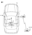
- FIG. 1 is a diagram showing a schematic configuration of an electronic key system for a vehicle.
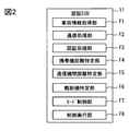
- FIG. 2 is a functional block diagram of the authentication ECU.
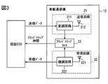
- FIG. 3 is a block diagram showing the configuration of the in-vehicle communication device.
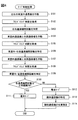
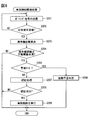
- FIG. 4 is a flowchart for explaining the mode control process.
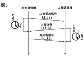
- FIG. 5 is a diagram illustrating a communication mode between in-vehicle communication devices.
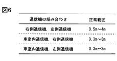
- FIG. 6 is a conceptual diagram of data indicating a normal range for each combination of in-vehicle communication devices.
- FIG. 7 is a diagram illustrating an aspect in which the right-side communication device is removed from the vehicle body and relaying is performed at the baseband level.
- FIG. 8 is a flowchart for explaining vehicle control-related processing.
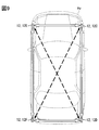
- FIG. 9 is a diagram illustrating a modification of the installation mode of the in-vehicle communication device.
- FIG. 1 is a diagram illustrating an example of a schematic configuration of a vehicle electronic key system 100 of the present disclosure.
- the vehicle electronic key system 100 includes an in-vehicle system 1 mounted on a vehicle Hv and a portable device 2 that is a communication terminal carried by a user of the vehicle Hv.
- the in-vehicle system 1 and the portable device 2 have a configuration for performing two-way wireless communication using radio waves in a predetermined frequency band.
- the in-vehicle system 1 and the portable device 2 are configured to be able to perform wireless communication of Ultra Wide Band-Impulse Radio (UWB-IR) system. That is, the in-vehicle system 1 and the portable device 2 are configured to be able to transmit and receive an impulse-shaped radio wave (hereinafter referred to as an impulse signal) used in UWB communication.
- An impulse signal used in UWB communication is a signal having a pulse width of an extremely short time (for example, 2 ns) and a bandwidth of 500 MHz or more (that is, an ultra-wide bandwidth).
- the UWB band in the present embodiment refers to the 3.1 GHz to 10.6 GHz band as an example. That is, the impulse signal in the present embodiment is realized using radio waves in the 3.1 GHz to 10.6 GHz band.
- the bandwidth of the impulse signal may be 500 MHz or more, and may have a bandwidth of 1.5 GHz or more.
- a modulation method for UWB-IR communication various methods such as a pulse-position modulation (PPM) method in which modulation is performed at a pulse generation position can be adopted.
- PPM pulse-position modulation
- OOK on-off modulation
- PWM pulse width modulation
- PAM pulse amplitude modulation
- PCM pulse code modulation
- the on / off modulation method is a method for expressing information (for example, 0 and 1) by the presence / absence of an impulse signal
- the pulse width modulation method is a method for expressing information by a pulse width.
- the pulse amplitude modulation method is a method for expressing information by the amplitude of an impulse signal.
- the pulse code modulation method is a method for expressing information by a combination of pulses.
- the portable device 2 is configured to return an impulse signal as a response signal when receiving the impulse signal from the in-vehicle system 1.
- the in-vehicle system 1 authenticates the portable device 2 by wirelessly communicating with the portable device 2.
- the in-vehicle system 1 performs predetermined vehicle control for the user to use the vehicle Hv based on the successful authentication of the portable device 2.
- the vehicle control for the user to use the vehicle Hv includes unlocking the vehicle door and starting the engine.
- the process in which the in-vehicle system 1 authenticates the portable device 2 refers to a regular portable device 2 in which a communication terminal that performs wireless communication for the in-vehicle system 1 (hereinafter, communication target) is associated with the in-vehicle system 1. This is a process of confirming that Successful authentication corresponds to the determination that the mobile device 2 is a legitimate portable device 2.
- the authentication of the portable device 2 by the in-vehicle system 1 may be performed by a challenge-response method. Details of the authentication process will be described later.
- a common encryption key used for the authentication process is stored in each of the portable device 2 and the in-vehicle system 1. Further, a unique identification number (hereinafter referred to as a portable device ID) is assigned to the portable device 2, and the portable device ID is registered in the in-vehicle system 1.
- the aforementioned encryption key may be a portable device ID.
- a unique identification number (hereinafter referred to as vehicle ID) is also assigned to the in-vehicle system 1, and the vehicle ID is registered in the portable device 2.
- the portable device 2 can be realized with the aid of communication terminals used for various purposes.
- the portable device 2 includes a portable device-side receiving circuit 21, a portable device-side control unit 22, and a portable device-side transmitting circuit 23.
- the portable device side control unit 22 is connected to each of the portable device side receiving circuit 21 and the portable device side transmitting circuit 23 so as to be communicable.
- the portable device side receiving circuit 21 is configured to receive an impulse signal in the UWB band. When the portable device side receiving circuit 21 receives the impulse signal, the portable device side receiving circuit 21 generates a received signal while performing electrical processing such as demodulating the signal, and outputs the received signal to the portable device side control unit 22.
- the portable device side receiving circuit 21 corresponds to a configuration for receiving a signal from the in-vehicle system 1.
- the portable device side control unit 22 When the reception signal is input from the portable device side receiving circuit 21, the portable device side control unit 22 generates a baseband signal corresponding to the response signal corresponding to this signal, and the baseband signal is transmitted to the portable device side transmission circuit. To 23.
- the portable device side control unit 22 receives a challenge signal, which will be described later, transmitted from the in-vehicle system 1, the baseband signal including a response code generated using an encryption key registered in advance in the portable device 2. Is generated.
- the baseband signal including the response code generated by the portable device side control unit 22 is output to the portable device side transmission circuit 23 and transmitted as a wireless signal.
- the portable device side control unit 22 generates a predetermined response signal when the portable device side reception circuit 21 receives a polling signal (described later) transmitted from the in-vehicle system 1, and cooperates with the portable device side transmission circuit 23. Work and send.
- the portable device side control unit 22 may be realized using a computer including a CPU, a RAM, a ROM, and the like. Note that the portable device-side control unit 22 may be realized using one or a plurality of ICs. In addition, the portable device control unit 22 may be realized using an MPU or a GPU. As will be described later, the portable device-side transmission circuit 23 is configured to convert a baseband signal into an impulse signal and transmit it. Therefore, the portable device side control unit 22 corresponds to a configuration in which the portable device side transmission circuit 23 transmits an impulse signal as a response signal when the portable device side reception circuit 21 receives the impulse signal.
- the portable device side transmission circuit 23 generates a response signal while performing electrical processing, such as modulating the baseband signal input from the portable device side control unit 22, and transmits the response signal by UWB communication.
- the portable device side transmission circuit 23 is configured to transmit a signal to the in-vehicle system 1. Note that it takes a predetermined time (hereinafter, response processing time) from when the portable device 2 receives the impulse signal from the in-vehicle system 1 to when the portable device 2 transmits the impulse signal as the response signal.
- the response processing time is determined according to the hardware configuration of the portable device 2.
- the expected value of the response processing time can be specified in advance by a test or the like.
- the in-vehicle system 1 includes an authentication ECU 11 and a plurality of in-vehicle communication devices 12.
- the authentication ECU 11 is an electronic control unit (ECU) that executes various processes such as a mode control process and a vehicle control process described later.
- the authentication ECU 11 corresponds to an authentication device.
- the authentication ECU 11 is configured as a computer including a CPU, a RAM, a flash memory 111, an I / O, and a bus line that connects these configurations.
- authentication ECU11 may be implement
- the flash memory 111 is a nonvolatile and rewritable memory.
- the flash memory 111 stores a program for causing the computer to function as the authentication ECU 11 (hereinafter, vehicle control program).
- vehicle control program As a specific storage medium for the vehicle control program, various non-transitional physical storage media can be employed. Executing the vehicle control program by the CPU corresponds to executing a method corresponding to the vehicle control program.
- the authentication ECU 11 has a vehicle information acquisition unit F1, a communication processing unit F2, and an authentication processing unit F3 as functions realized by the CPU executing a vehicle control program stored in the flash memory 111.
- the mobile device distance specifying unit F4, the inter-communication device distance specifying unit F5, the leaving device specifying unit F6, the mode control unit F7, and the control execution unit F8 are provided.
- some or all of the various functional blocks included in the authentication ECU 11 may be realized as hardware.
- a mode in which a certain function is realized as hardware includes a mode in which one or a plurality of ICs are used.
- some or all of the various functional blocks may be realized by cooperation of execution of software by a CPU or the like and a hardware configuration.
- the vehicle information acquisition unit F1 acquires various information (hereinafter referred to as vehicle information) indicating the state of the vehicle Hv from sensors or switches mounted on the vehicle Hv.
- vehicle information includes, for example, door open / closed states, door locked / unlocked states, shift positions detected by a shift position sensor, vehicle Hv power state (eg, ignition power on / off), and parking brake operation. State, etc. Note that the types of information included in the vehicle information are not limited to those described above.
- the vehicle information includes a detection result of a brake sensor for detecting whether or not a brake pedal (not shown) is depressed.
- the vehicle information acquisition unit F1 identifies the current state of the vehicle Hv based on the various information described above. For example, the vehicle information acquisition unit F1 determines that the vehicle Hv is parked when the engine is off and all the doors are locked. Of course, the conditions for determining that the vehicle Hv is parked may be appropriately designed, and various determination conditions can be applied. Details of the communication processing unit F2, the authentication processing unit F3, the portable device distance specifying unit F4, the inter-communication device distance specifying unit F5, the leaving machine specifying unit F6, the mode control unit F7, and the control execution unit F8 will be separately described later.
- the authentication ECU 11 is connected to each of the plurality of in-vehicle communication devices 12 so as to be able to communicate with each other via, for example, a dedicated signal line. Note that the authentication ECU 11 may be connected to each of the plurality of in-vehicle communication devices 12 via a communication network built in the vehicle so as to be able to communicate with each other.
- the authentication ECU 11 is also connected to a body ECU and an engine ECU (not shown) so as to be able to communicate with each other via a communication network.
- the body ECU is an ECU that executes various processes related to vehicle body control. For example, the body ECU drives a door lock motor provided in each door based on an instruction from the authentication ECU 11 to lock and unlock each door.
- the engine ECU is an ECU that controls the operation of the engine mounted on the vehicle Hv. For example, when the engine ECU acquires a start instruction signal for instructing start of the engine from the authentication ECU 11, the engine ECU is started.
- the vehicle Hv is a vehicle including an engine as a power source, but is not limited thereto.
- the vehicle Hv may be a so-called hybrid vehicle that includes an engine and a motor as power sources, or may be an electric vehicle that includes only a motor as a power source.
- the authentication ECU 11 of the present embodiment has two types of operation modes, a normal mode and a warning mode, as operation modes.
- the normal mode is an operation mode in which predetermined vehicle control is performed based on the successful authentication of the portable device 2.
- the alert mode is an operation mode in which the execution of the authentication process by wireless communication is canceled (that is, the authentication process is not executed).
- the alert mode may be an operation mode in which vehicle control is not executed even when the authentication of the portable device 2 is successful.
- the in-vehicle communication device 12 is a communication device for performing wireless communication (here, UWB communication) with the portable device 2.
- Each of the plurality of in-vehicle communication devices 12 is configured to be able to perform UWB communication with other in-vehicle communication devices 12 mounted on the vehicle Hv. That is, each in-vehicle communication device 12 is configured to be able to communicate with the portable device 2 and the other in-vehicle communication device 12.
- another in-vehicle communication device 12 for a certain in-vehicle communication device 12 is also referred to as another device.
- the in-vehicle system 1 only needs to include at least two in-vehicle communication devices 12. At least one of the plurality of in-vehicle communication devices 12 is disposed on the outer surface portion of the vehicle Hv.
- the outer surface portion is a body portion that contacts the vehicle exterior space in the vehicle Hv, and includes a side surface portion, a rear surface portion, and a front surface portion of the vehicle Hv.
- the in-vehicle system 1 of this embodiment includes a right communication device 12A, a left communication device 12B, and a vehicle interior communication device 12X as the in-vehicle communication device 12.
- the right communication device 12A is an in-vehicle communication device 12 for forming a communication area mainly on the right side of the vehicle.
- the right communicator 12A is provided in the vicinity of the outer door handle disposed at the front seat door on the right side of the vehicle, for example.
- the outer door handle refers to a gripping member (so-called door handle) provided on the outer surface of the door for opening and closing the door.
- the vicinity of the outer door handle includes the inside of the outer door handle.
- the left communication device 12B is an in-vehicle communication device 12 for forming a communication area mainly on the right side of the vehicle.
- the left communication device 12B is provided on an outer door handle disposed on a front seat door on the left side of the vehicle.
- the in-vehicle communication device 12 arranged on the outer surface portion of the vehicle Hv such as the right communication device 12A and the left communication device 12B is also referred to as an out-of-vehicle communication device.
- the in-vehicle communication device 12X is an in-vehicle communication device 12 for forming a communication area mainly in the entire vehicle interior.
- the vehicle interior communication device 12X is disposed at a position where wireless communication can be performed with the in-vehicle communication device 12 disposed on the outer surface portion of the vehicle Hv, such as the right communication device 12A and the left communication device 12B.
- the vehicle interior communication device 12X is arranged at the center of the ceiling in the vehicle interior.
- the vehicle interior communication device 12X may be disposed on a surface portion on the indoor side of the B pillar. Further, the vehicle interior communication device 12X may be provided in the vehicle width direction center of the instrument panel or in the vicinity of the center console box. Although only one in-vehicle communication device 12X is shown here, a plurality of in-vehicle communication devices 12X may be provided in the vehicle interior.
- the vehicle interior communication device 12X is preferably arranged at a position where the outside of the vehicle interior can be seen so that the radio signal propagates not only inside the vehicle interior but also outside the vehicle interior.
- the vehicle interior communication device 12X can be disposed at any position in the vehicle interior.
- the installation mode (specifically, the installation position and the number of installations) of the in-vehicle communication device 12 is not limited to the above-described mode.
- the vehicle exterior communication device may be disposed on the outer surface of the B pillar of the vehicle Hv.
- the vehicle exterior communication device may be disposed near the boundary between the side surface portion and the roof portion of the vehicle Hv (hereinafter, the side surface upper end portion).
- Such a configuration corresponds to a configuration in which the vehicle exterior communication device is provided in a portion located on the upper side of the side window.
- the upper end portion of the side surface corresponds to a portion where the upper end portion of the door of the vehicle Hv contacts the roof portion of the vehicle Hv.
- the vehicle-mounted system 1 may be provided with the vehicle-mounted communication apparatus 12 which makes the inside of a trunk a communication area, and the vehicle-mounted communication apparatus 12 arrange
- Each vehicle-mounted communication device 12 is set with a unique communication device number.
- the communication device number functions as information for identifying a plurality of in-vehicle communication devices 12.
- the operation of each in-vehicle communication device 12 is controlled by the authentication ECU 11.
- Each of the plurality of in-vehicle communication devices 12 includes a transmission circuit 31, a reception circuit 32, and a round trip timer 33 as shown in FIG.
- the transmission circuit 31 is configured to generate an impulse signal while performing electrical processing, such as modulating a baseband signal input from the authentication ECU 11, and to radiate this impulse signal as a radio wave.
- the transmission circuit 31 is realized using, for example, a modulation circuit 311 and a transmission antenna 312.
- the modulation circuit 311 is a circuit that modulates the baseband signal input from the authentication ECU 11.
- the modulation circuit 311 generates a modulation signal corresponding to data (hereinafter referred to as transmission data) indicated by the baseband signal input from the authentication ECU 11 and transmits the modulation signal to the transmission antenna 312.
- the modulation signal is a signal obtained by modulating transmission data by a predetermined modulation method (for example, PCM modulation method).
- the modulation signal means a signal sequence in which a plurality of impulse signals are arranged at time intervals corresponding to transmission data.
- the modulation circuit 311 includes a circuit that generates an electrical impulse signal (hereinafter referred to as a pulse generation circuit) and a circuit that amplifies and shapes the impulse signal.
- the transmission antenna 312 is configured to convert the electrical impulse signal output from the modulation circuit 311 into a radio wave and radiate it into space. That is, the transmission antenna 312 radiates a pulsed radio wave having a predetermined bandwidth in the UWB band as an impulse signal.
- the modulation circuit 311 simultaneously outputs a signal indicating that the impulse signal has been output (hereinafter, a transmission notification signal) to the round trip timer 33. .
- the transmission circuit 31 of the present embodiment is configured such that the rise time of the impulse signal is 1 ns.
- the rise time is the time required for the signal intensity to exceed 10% of the maximum amplitude for the first time until it exceeds 90% of the maximum amplitude.
- the rise time of the impulse signal is determined according to the hardware configuration such as the circuit configuration of the transmission circuit 31.
- the rise time of the impulse signal can be specified by simulation or actual test. In general, the rise time of an impulse signal in the UWB band is about 1 ns.
- the receiving circuit 32 is a configuration for receiving a radio signal conforming to a communication standard adopted in the vehicle electronic key system 100 such as an impulse signal as a response signal transmitted from the portable device 2.
- the reception circuit 32 includes, for example, a reception antenna 321 and a demodulation circuit 322.
- the receiving antenna 321 is an antenna for receiving an impulse signal.
- the reception antenna 321 outputs an electrical impulse signal corresponding to the impulse signal transmitted by the portable device 2 to the demodulation circuit 322.
- the demodulation circuit 322 When the reception antenna 321 receives the UWB band impulse signal, the demodulation circuit 322 generates a reception signal while performing electrical processing such as demodulating the signal, and outputs the reception signal to the authentication ECU 11. That is, the demodulation circuit 322 is configured to demodulate a series of modulated signals (hereinafter referred to as pulse series signals) composed of a plurality of impulse signals transmitted from the portable device 2 or other devices, and restore the data before modulation. For example, the demodulation circuit 322 acquires a pulse series signal transmitted from the portable device 2 or another in-vehicle communication device 12 based on the impulse signal input from the reception antenna 321.
- pulse series signals composed of a plurality of impulse signals transmitted from the portable device 2 or other devices
- the pulse series signal acquired by the demodulation circuit 322 is a series of a plurality of impulse signals input from the receiving antenna 321 arranged in time series with an actual reception interval.
- the demodulation circuit 322 includes a frequency conversion circuit that converts the frequency of the impulse signal received by the reception antenna 321 into a baseband signal and outputs the signal, an amplification circuit that amplifies the signal level, and the like.
- the reception circuit 32 when an impulse signal is input from the reception antenna 321, the reception circuit 32 outputs a signal indicating that the impulse signal has been received (hereinafter, a reception notification signal) to the round trip timer 33.
- the round trip timer 33 is a timer that measures the time from the transmission circuit 31 transmitting the impulse signal to the reception circuit 32 receiving the impulse signal (hereinafter, round trip time).
- the timing at which the transmission circuit 31 transmits the impulse signal is specified by the input of the transmission notification signal.
- the timing at which the reception circuit 32 receives the impulse signal is specified by the input of the reception notification signal. That is, the round trip timer 33 of this embodiment is configured to measure the time from when the modulation circuit 311 outputs the transmission notification signal until the demodulation circuit 322 outputs the reception notification signal.
- the round trip time corresponds to the signal flight time.
- the round trip timer 33 measures the elapsed time after the transmission circuit 31 transmits the impulse signal by counting the clock signal input from a clock oscillator (not shown). Counting by the round trip timer 33 is stopped when a reception notification signal is input or when a predetermined upper limit value is reached, and the count value is output to the authentication ECU 11. That is, the round trip time is reported to the authentication ECU 11. When reporting of the round trip time to the authentication ECU 11 is completed, the count value of the round trip timer 33 returns to 0 (that is, is reset).
- the mode control process may be executed at a predetermined monitoring period while the vehicle information acquisition unit F1 determines that the vehicle Hv is parked.
- the electric power for the vehicle-mounted system 1 to perform mode control processing should just be supplied from the vehicle-mounted battery which is not shown in figure.
- the monitoring cycle may be appropriately designed such as 500 milliseconds, 1 second, 5 seconds, 1 minute, or the like.
- the communication processing unit F2 operates the right communication device 12A and the left communication device 12B to perform wireless communication in both directions. Specifically, as shown in FIG. 5, the right communication device 12A is caused to transmit a pulse series signal that functions as a response request signal destined for the left communication device 12B. Along with this, the round trip timer 33 of the right communication device 12A starts measuring the elapsed time since the response request signal was transmitted. That is, the round trip time measurement is started.
- the response request signal is a signal for requesting the return of the response signal.
- the response request signal includes, for example, the communication device number of the in-vehicle communication device 12 as the destination (here, the communication device number of the left communication device 12B) as the destination information. By including the destination information in the response request signal, it is possible to prevent the in-vehicle communication device 12 or the portable device 2 other than the destination from returning the response signal. Further, the response request signal includes the communication device number of the in-vehicle communication device 12 that is the transmission source (here, the communication device number of the right communication device 12A) as the transmission source information. When the response request signal includes the transmission source information, the in-vehicle communication device 12 that has received the response request signal can specify the destination of the response signal (in other words, the return destination).
- the left communication device 12B When the left communication device 12B receives the response request signal, it transmits a pulse series signal that functions as a response signal. That is, a response signal designating the transmission source information indicated in the response request signal as a destination is transmitted.
- the response signal also includes destination information and transmission source information.
- the round trip timer 33 of the left communication device 12B starts measuring the elapsed time (that is, the round trip time) since the transmission of the impulse signal with the transmission of the response signal as a trigger.
- the round trip timer 33 of the right communication device 12A stops measuring the round trip time and reports the measured round trip time to the authentication ECU 11.
- the right communication device 12A receives the response signal from the left communication device 12B, the right communication device 12A transmits a re-response signal that is a response signal to the response signal.
- the re-response signal is a pulse series signal that functions as a response signal.
- the re-response signal also includes transmission source information and destination information. Note that the response request signal, the response signal, and the reresponse signal do not need to include destination information and transmission source information, as will be described later separately as Modification 1.
- the response request signal, the response signal, and the reresponse signal may be a single impulse signal.
- the round trip timer 33 of the left communication device 12B When the round trip timer 33 of the left communication device 12B receives the re-response signal from the right communication device 12A, it stops measuring the round trip time and reports the measured round trip time to the authentication ECU 11.
- the round trip time measured by each of the right communication device 12A and the left communication device 12B functions as an index (hereinafter, distance index information) indicating the distance between the right communication device 12A and the left communication device 12B.
- the inter-communication device distance specifying unit F5 acquires the round trip time from each of the right communication device 12A and the left communication device 12B, and proceeds to S103.
- the distance between the left and right communication devices which is the distance between the right communication device 12A and the left communication device 12B, is calculated based on the round trip time acquired in S102.
- the inter-communication distance specifying unit F5 subtracts the estimated value of the response processing time in the left communication device 12B from the round trip time acquired from the right communication device 12A, and further divides the calculated value by two to fly one way. Calculate time. Then, by multiplying the one-way flight time by the propagation speed of radio waves in the air, the distance between the left and right communication devices based on the round trip time acquired from the right communication device 12A is calculated. Further, the inter-communication device distance specifying unit F5 calculates the distance between the left and right communication devices based on the round trip time acquired from the left communication device 12B by the same procedure.
- the distance between the left and right communication devices based on the round trip time acquired from the right communication device 12A and the average value of the distance between the left and right communication devices based on the round trip time acquired from the left communication device 12B are finally determined as the distance between the left and right communication devices.
- the assumed value of the response processing time in the in-vehicle communication device 12 the assumed value of the response processing time in the portable device 2, and the propagation speed of the radio wave are registered in the flash memory 111 as calculation parameters.
- the calculation method of the distance between the left and right communication devices can be changed as appropriate.
- the distance between the left and right communication devices based on the round trip time acquired from the right communication device 12A may be adopted as it is as the final distance between the left and right communication devices.
- the left communication device 12B does not need to measure the round trip time in the first place, and the right communication device 12A does not need to transmit a re-response signal.
- the process in S103 proceeds to S104.
- the communication processing unit F2 activates the vehicle interior communication device 12X and the right communication device 12A, and performs wireless communication in both directions.
- the communication content between the in-vehicle communication device 12X and the right communication device 12A is the same as S101.
- the response request signal may be transmitted from the in-vehicle communication device 12X or may be transmitted from the right communication device 12A.
- the communication processing unit F2 controls the vehicle interior communication device 12X to transmit a response request signal to the right communication device 12A.
- the round trip time representing the distance between the vehicle interior communication device 12X and the right communication device 12A is measured in each of the vehicle interior communication device 12X and the right communication device 12A.
- the inter-communication device distance specifying unit F5 acquires the round trip time from each of the in-vehicle communication device 12X and the right communication device 12A, and proceeds to S106.
- S106 based on the round trip time acquired in S104, the distance between the vehicle interior and the right communication device, which is the distance between the vehicle communication device 12X and the right communication device 12A, is calculated.
- the calculation mode can be the same as the calculation method of the distance between the left and right communication devices. That is, the temporary vehicle interior-right communication device distance is calculated based on the round trip time acquired from the vehicle interior communication device 12X. Further, based on the round trip time acquired from the right communication device 12A, the temporary vehicle interior-right communication device distance is calculated.
- the average value of the distance between the vehicle interior and the right communication device based on the round trip time acquired from the vehicle interior communication device 12X and the distance between the left and right communication devices based on the round trip time acquired from the right communication device 12A is finally obtained. Adopted as the distance between the vehicle interior and the right communication device.
- the communication processing unit F2 operates the vehicle interior communication device 12X and the left communication device 12B, and performs wireless communication in both directions.
- the communication content between the vehicle interior communication device 12X and the left communication device 12B is the same as S101 and S104.
- the response request signal may be transmitted from the in-vehicle communication device 12X or from the left communication device 12B.
- the communication processing unit F2 controls the vehicle interior communication device 12X to transmit a response request signal to the left communication device 12B.
- the round trip time representing the distance between the in-vehicle communication device 12X and the left communication device 12B is measured in each of the in-vehicle communication device 12X and the left communication device 12B.
- the inter-communication device distance specifying unit F5 acquires the round trip time from each of the in-vehicle communication device 12X and the left communication device 12B, and proceeds to S109.
- the distance between the vehicle interior and left communication device which is the distance between the vehicle communication device 12X and the left communication device 12B, is calculated.
- the calculation mode can be the same as the calculation method of the distance between the left and right communication devices described above. That is, based on the round trip time acquired from the vehicle interior communication device 12X, the temporary vehicle interior-left communication device distance is calculated. Further, based on the round trip time acquired from the left communication device 12B, a temporary vehicle interior-left communication device distance is calculated.
- the average value of the distance between the vehicle interior and the left communication device based on the round trip time acquired from the vehicle interior communication device 12X and the distance between the left and right communication devices based on the round trip time acquired from the left communication device 12B is finally obtained.
- the distance between two in-vehicle communication devices 12 disposed at different positions such as the distance between the left and right communication devices, the distance between the vehicle interior and the right communication device, and the distance between the vehicle interior and the left communication device. Also described as the distance between communicators.
- the departure machine specifying unit F6 executes S110.
- the separation machine specifying unit F6 determines whether or not the distances between the various communication devices calculated by the above processing are within a normal range set in advance for each combination of the in-vehicle communication devices 12.
- Data indicating the normal range for each combination of the in-vehicle communication devices 12 (hereinafter, normal range data) is stored in the flash memory 111 as a part of the control execution unit program, for example.
- FIG. 6 is a conceptual diagram showing a configuration of normal range data.
- the normal range according to the combination of the in-vehicle communication devices 12 may be set to a value obtained by adding a distance measurement error to the distance between the in-vehicle communication devices 12 determined by the mounting position of each in-vehicle communication device 12.
- the upper limit value of the normal range corresponds to a threshold value for the authentication ECU 11 to determine that the in-vehicle communication device 12 is removed from the vehicle Hv and relayed at the baseband level.
- the state in which the relay is performed at the baseband level corresponds to a state in which a baseband signal from the authentication ECU 11 to the in-vehicle communication device 12 or a baseband signal from the in-vehicle communication device 12 to the authentication ECU 11 is being relayed. To do.
- the distance between communication devices calculated by the above method is assumed to be 10 m or more.
- the upper limit value of the normal range may be a value larger than the size of the vehicle Hv, such as 5 m or 10 m.
- the lower limit value of the normal range may be set as appropriate, and may be 0 m, for example.
- the normal range may be defined only by the upper limit value.
- S110 If the result of determination in S110 is that there is an inter-communication device distance that deviates from the normal range corresponding to the combination of the in-vehicle communication devices 12 among the multiple inter-communication device distances, S112 is executed. On the other hand, when the distances between the plurality of communication devices are all within the normal range corresponding to the combination of the in-vehicle communication devices 12, S111 is executed.
- the mode control unit F7 sets the operation mode of the authentication ECU 11 to the normal mode and ends this flow.
- the mode control unit F7 sets the operation mode of the authentication ECU 11 to the alert mode, and proceeds to S113.
- the separation machine specifying unit F6 removes the vehicle-mounted communication device that has been removed from the vehicle body based on the combination of the vehicle-mounted communication devices 12 in which the distance between the communication devices is outside the normal range (in other words, an incorrect value). 12 (hereinafter referred to as a vehicle departure machine) is identified.
- the vehicle leaving device is the right communication device 12A.
- the vehicle leaving device can be specified as the left communication device 12B.
- the departure machine specifying unit F6 executes S114.
- the leaving machine specifying unit F6 specifies the position of the vehicle leaving machine based on the distance between at least two communication devices related to the vehicle leaving machine and the installation position of the in-vehicle communication device 12 other than the vehicle leaving machine.
- the inter-communication device distance related to the vehicle leaving machine is the inter-communication machine distance for a combination of in-vehicle communication devices including the vehicle leaving machine. For example, when the vehicle leaving device is the right communication device 12A, the distance between the left and right communication devices and the distance between the vehicle interior and the right communication device correspond to the distance between the communication devices related to the vehicle leaving device.
- the vehicle leaving device is the left communication device 12B, the distance between the left and right communication devices and the distance between the vehicle interior and the left communication device correspond to the distance between the communication devices related to the vehicle departure device.
- the departure device specifying unit F6 includes the distance between the left and right communication devices, the distance between the vehicle interior and the right communication device, the mounting position of the left communication device 12B, and the vehicle interior communication device 12X. Is estimated (e.g., calculated) based on the mounting position of the right communication device 12 ⁇ / b> A as the vehicle departure device. Specifically, it is determined that the right communication device 12A exists at a point that is the distance between the left communication device 12B and the left and right communication devices, and that is the vehicle interior communication device-right communication device distance from the vehicle interior communication device 12X. There are two points that satisfy the above conditions. The departure machine specifying unit F6 may determine that a vehicle departure machine exists at one of the two locations.
- the separation device specifying unit F6 specifies the position of the left communication device 12B as the vehicle release device in the same manner. That is, based on the distance between the left and right communication devices, the distance between the vehicle interior and the left communication device, the mounting position of the right communication device 12A, and the mounting position of the vehicle communication device 12X, the position of the left communication device 12B as the vehicle release device is determined. Identify.
- the in-vehicle system 1 includes four or more in-vehicle communication devices 12 and the number of vehicle leaving devices is one, the number of in-vehicle communication devices (hereinafter, remaining devices) other than the vehicle leaving devices is three. That's it. In other words, there are three or more reference points that can be used for calculating the position of the vehicle leaving machine. When there are at least three reference points that can be used for calculating the position of the vehicle leaving machine, the position of the vehicle leaving machine can be specified in one place.
- the in-vehicle communication device 12 corresponding to the vehicle leaving machine specified by the leaving machine specifying unit F6 and the position information of the vehicle leaving machine may be held in the memory until the operation mode is set to the normal mode.
- the authentication ECU 11 uses the display mounted on the vehicle Hv or the portable device 2 to obtain the position information of the in-vehicle communication device 12 and the vehicle leaving device corresponding to the vehicle leaving device specified by the leaving device specifying unit F6. It may be configured to notify. According to such a configuration, security can be further improved.
- the vehicle control-related process is a process for the authentication ECU 11 to perform vehicle control for the user to use the vehicle Hv based on the result of wireless communication with the portable device 2.
- the vehicle control related process is executed, for example, at a timing when a predetermined time (for example, 10 seconds) has elapsed since the time when the vehicle Hv shifted to the parking state.
- the vehicle control related processing may be configured to be executed sequentially while the vehicle information acquisition unit F1 determines that the vehicle Hv is parked, for example.
- the communication processing unit F2 transmits a polling signal from a predetermined in-vehicle communication device 12 (for example, the in-vehicle communication device 12X), and the process proceeds to S202.
- the polling signal is a wireless signal that does not include a challenge code and requests the portable device 2 to return a response signal. Since the polling signal may play a role of returning the portable device 2 from the sleep mode to the normal mode, the polling signal may be referred to as a wake signal.
- the authentication ECU 11 as the authentication processing unit F3 receives a response signal from the portable device 2 with respect to the polling signal so that a communication terminal that may be the portable device 2 is within the communication area of the vehicle Hv. Can be detected.
- the polling signal includes source information and destination information.
- the round trip timer 33 of the in-vehicle communication device 12 (hereinafter referred to as the working communication device) that is the transmission source of the polling signal starts to measure the elapsed time after transmitting the polling signal. That is, the round trip time measurement is started.
- S202 it is determined whether or not the operating communication device has received a response signal to the polling signal transmitted in S201.
- the operating communication device receives the response signal, an affirmative determination is made in S202, and the process proceeds to S203.
- the round trip timer 33 of the working communication device stops measuring the round trip time and reports the measured round trip time to the authentication ECU 11. This round trip time functions as information indicating the distance from the working communication device to the portable device 2 (hereinafter, portable device distance related information).
- S201 to S202 are processes for transmitting polling signals in order from the plurality of in-vehicle communication devices 12. Note that the order in which the polling signals are transmitted in the plurality of in-vehicle communication devices 12 may be appropriately designed.
- the portable device distance specifying unit F4 calculates the portable device distance that is the distance from the working communication device to the portable device 2 based on the round trip time reported from the working communication device, and proceeds to S204.
- the calculation method of the portable device distance based on the round trip time can be implemented by the same method as the calculation of the distance between communication devices.
- the authentication processing unit F3 determines whether or not the portable device distance calculated in S203 is less than a predetermined operation threshold.
- the operation threshold value corresponds to the upper limit value of the communication device distance that permits execution of vehicle control.
- the operation threshold value is set to a value indicating that the portable device 2 is present in the vicinity of the vehicle Hv or in the vehicle interior, such as 1 m or 2 m, for example. Note that the operating threshold may be set to 5 m.
- the authentication processing unit F3 determines whether or not the operation mode of the authentication ECU 11 is set to the alert mode by the mode control unit F7. When the operation mode of the authentication ECU 11 is set to the alert mode, S206 is executed. On the other hand, when the operation mode of the authentication ECU 11 is set to the normal mode, S207 is executed.
- the authentication processing unit F3 determines that the portable device distance calculated in S203 is an invalid value, and ends this flow. As described above, when the authentication ECU 11 according to the present embodiment determines that the portable device distance is incorrect, the authentication ECU 11 does not perform vehicle control for the user to use the vehicle Hv. If it is determined that the portable device distance is invalid, the vehicle control related process may be executed again from S201.
- the mode control unit F7 sets the operation mode of the authentication ECU 11 to the alert mode
- at least one of the inter-communication device distances for each combination of the in-vehicle communication devices 12 corresponds to the combination of the in-vehicle communication devices 12. This is a case where it deviates from a predetermined normal range.
- such a configuration is such that when at least one of the distances between communication devices for each combination of the in-vehicle communication devices 12 deviates from a predetermined normal range corresponding to the combination of the in-vehicle communication devices 12, the vehicle This corresponds to a configuration in which control is not executed.
- the authentication processing unit F3 executes the authentication processing of the portable device 2 in cooperation with the communication processing unit F2. Specifically, the authentication processing unit F3 requests the communication processing unit F2 to transmit a signal including a challenge code (hereinafter referred to as a challenge signal) from the operating communication device. The communication processing unit F2 transmits a challenge signal from the working communication device based on the request from the authentication processing unit F3.
- a challenge signal a challenge code
- the challenge code is a code for authenticating the portable device 2.
- the challenge code may be a random number generated using a random number table or the like.
- the portable device 2 encrypts the challenge code using an encryption key registered in advance in the portable device 2, and a signal including the encrypted code (hereinafter, response code) (hereinafter, response code). Response signal).
- the authentication processing unit F3 transmits a challenge signal and generates a code (hereinafter referred to as a verification code) obtained by encrypting the challenge code using an encryption key held by itself.
- S208 it is determined whether or not the authentication process is successful. For example, if the response signal can be received from the portable device 2 and the response code indicated in the response signal matches the verification code, it is determined that the authentication is successful. On the other hand, if the response code cannot be received even after the response waiting time has elapsed since the challenge signal was transmitted, it is determined that the authentication has failed. Even if the response code can be received, if the response code indicated by the response signal does not match the verification code, it is determined that the authentication has failed.
- the control execution unit F8 executes predetermined vehicle control for the user to use the vehicle Hv according to the scene when the authentication process is successful (in other words, the state of the vehicle Hv). For example, when the vehicle Hv is parked, the control execution unit F8 sets the door lock mechanism of the vehicle Hv to an unlocked state or a venue preparation state in cooperation with a body ECU (not shown).
- the venue preparation state is a state in which the user can unlock the door only by touching a button or a touch sensor arranged on the door.
- the control execution unit F8 starts the engine in cooperation with the engine ECU.
- the content of the vehicle control performed by the control execution unit F8 is appropriately determined according to the scene when the authentication process is successful (in other words, the state of the vehicle Hv).
- the authentication ECU 11 performs bidirectional wireless communication for each combination of the in-vehicle communication devices 12 in a positional relationship capable of wireless communication with each other, and based on the round trip time obtained as a result of the communication, It is determined whether the distance is a normal value.
- execution of vehicle control such as unlocking the vehicle door is performed. Is prohibited (or put on hold).
- the in-vehicle communication device 12 arranged on the outer surface portion of the vehicle Hv is removed from the vehicle Hv together with the module, and the relay at the baseband signal level is performed.
- the fear that the vehicle Hv is illegally used can be suppressed.
- a mode in which execution of vehicle control is prohibited by regarding the mobile device distance specified by the mobile device distance specifying unit F4 as an illegal value has been disclosed.
- the configuration in which vehicle control is not executed when there is a distance between communication devices that deviates from the normal range according to the combination of the in-vehicle communication devices 12 among the plurality of communication device distances is not limited thereto.
- the authentication process may not be executed. good. If the authentication process is not executed, the authentication is not successful. Therefore, execution of vehicle control can be prohibited also by the above configuration.
- a polling signal or the like is directed to the portable device 2
- You may be comprised so that transmission of a signal may be stopped. Also with the above configuration, execution of vehicle control can be prohibited.
- ⁇ Modification 1> when specifying the distance between the communication devices, a mode in which the two in-vehicle communication devices 12 to be distance-measuring exchange signals including the transmission source information and the destination information is disclosed, but the present invention is not limited thereto.
- the in-vehicle communication device 12 may be configured to measure the round trip time by transmitting and receiving a single impulse signal.
- the in-vehicle communication device 12 transmits a single impulse signal as a response request signal based on an instruction from the authentication ECU 11. Moreover, the two vehicle-mounted communication apparatuses 12 which provide the combination made into a ranging object return a single impulse signal as a response signal and a reresponse signal, when a single impulse signal is received.
- the authentication ECU 11 in this modification controls the vehicle-mounted communication devices 12 other than the combinations to be distance-measured to stop the operation or not to return a single pulse signal as a response signal even if a single pulse signal is received. Is done. For example, while the processing for measuring the distance between the left and right communication devices is being performed in S101 to S103, the vehicle interior communication device 12X stops its operation.
- the state in which the vehicle-mounted communication device 12 has stopped operating is a state in which signal transmission / reception is not performed.
- the portable device 2 of the present modification is also configured not to return a single pulse signal as a response signal even when a single impulse signal is received.
- the round trip time includes the time required for the arithmetic processing for generating the response signal (that is, the response processing time). It becomes difficult. As a result, it is possible to improve the distance measurement accuracy of the distance between the communication devices.
- ⁇ Modification 2> a mode in which the distance between communication devices is calculated using the round trip time is disclosed, but the index for calculating the distance between communication devices is not limited to the round trip time.
- Each in-vehicle communication device 12 reports the reception intensity of the signal transmitted from the other device to the authentication ECU 11 as distance index information, and the inter-communication device distance specifying unit F5 is based on the reception intensity detected by each in-vehicle communication device 12. You may be comprised so that the distance between communication apparatuses may be calculated.
- each in-vehicle communication device 12 may be configured to generate a one-way flight time as distance index information.
- the one-way flight time is the difference between the time when the other aircraft transmits a signal and the time when the signal is actually received.
- the one-way flight time can be calculated by predefining the time at which each in-vehicle communication device 12 transmits a signal.
- various methods can be used as a method of calculating the distance between communication devices.
- each vehicle-mounted communication device 12 reports the round trip time to the authentication ECU 11, and the authentication ECU 11 calculates the distance between the communication devices based on the round trip time provided from each vehicle-mounted communication device 12.
- Each in-vehicle communication device 12 may have a function of calculating the distance between communication devices based on the round trip time. That is, each in-vehicle communication device 12 calculates the distance from its own device to the other device as a communication partner based on the round trip time measured when wirelessly communicating with the other device. And the data which show the said distance are matched with the communication apparatus number about each of a communicating party and an own machine, and are reported to authentication ECU11.
- each in-vehicle communication device 12 may be configured to calculate a distance based on the reception intensity of a signal received from another device.
- the data indicating the round trip time generated by the in-vehicle communication device 12 and the data indicating the reception intensity correspond to distance-related information that indirectly indicates the distance to the other device.
- the data indicating the distance corresponds to the distance related information that directly indicates the distance to the other device.
- the aspect provided with the vehicle interior communication apparatus 12X was disclosed, it is not restricted to this.
- the vehicle interior communication device 12X may not be provided.
- all the in-vehicle communication devices 12 may be arranged on the outer surface portion of the vehicle Hv.
- the in-vehicle system 1 may be arranged in the four corners of the vehicle Hv.
- the in-vehicle communication device 12C shown in FIG. 9 is the in-vehicle communication device 12 disposed in the right corner portion at the front end of the vehicle.
- the in-vehicle communication device 12D is the in-vehicle communication device 12 disposed in the right corner portion at the rear end of the vehicle.
- the in-vehicle communication device 12E is the in-vehicle communication device 12 disposed in the left corner portion at the front end of the vehicle.
- the in-vehicle communication device 12F is the in-vehicle communication device 12 disposed in the left corner portion at the rear end of the vehicle.
- the authentication ECU 11 is not shown.
- white arrows in FIG. 9 indicate combinations of the in-vehicle communication devices 12 configured to be able to communicate with each other wirelessly. As shown in FIG. 9, it may be configured not to / cannot perform wireless communication with the vehicle-mounted communication device 12 positioned diagonally.
- Each in-vehicle communication device 12 may be configured to be capable of wireless communication with at least one other device.
- the combination of the in-vehicle communication devices 12 to be used for calculating the distance between the communication devices may be designed as appropriate.
- each of the in-vehicle communication devices 12C to 12F may be configured to be able to perform wireless communication with other devices existing at diagonal positions as indicated by broken line arrows.
- the in-vehicle system 1 and the portable device 2 disclose a configuration in which wireless communication is performed by the Impulse Radio method, but is not limited thereto.
- the in-vehicle system 1 and the portable device 2 may be configured to perform wireless communication by a MultiBand Orthogonal Frequency Division Multiplexing (MB-OFDM) method, a Direct Sequence UWB (DS-UWB) method, or the like.
- the in-vehicle system 1 and the portable device 2 are connected to each other by wireless communication (hereinafter, short-range communication) compliant with a short-range wireless communication standard such as Bluetooth (registered trademark), Wi-Fi (registered trademark), or ZigBee (registered trademark). ) May be implemented. You may be comprised so that wireless communication may be implemented using the radio wave of LF band, and the radio wave of UHF band.
- the means and / or function provided by the authentication ECU 11 can be provided by software recorded in a substantial memory device and a computer that executes the software, only software, only hardware, or a combination thereof.
- the authentication ECU 11 when it is provided by an electronic circuit that is hardware, it can be provided by a digital circuit including a large number of logic circuits, or an analog circuit. Further, the authentication ECU 11 can be provided by one computer or a set of computer resources configured to be able to communicate with each other.
- the portable device 2 may be any device that is carried by the user and has a function as an electronic key of the vehicle Hv.
- the function as the electronic key of the vehicle Hv is specifically a function of transmitting a signal (for example, a response signal) including information proving that the key is the vehicle Hv based on a request from the in-vehicle system 1.
- the portable device 2 may be a rectangular, elliptical (fob type), or card-type small device conventionally known as a smart key.
- the portable device 2 may be configured as a wearable device that is worn on a user's finger or arm.
- the portable device 2 may be an information processing terminal such as a smartphone or a tablet terminal.
Abstract
車両用電子キーシステムは、複数の車載通信機(12、12A~12F、12X)と認証装置(11)と、を備える。複数の車載通信機のそれぞれは、他の車載通信機と無線通信を実施し、他の車載通信機から送信された信号に基づいて他の車載通信機までの距離を直接的又は間接的に示す距離関連情報を生成する。認証装置は、複数の車載通信機のそれぞれが生成した複数の距離関連情報に基づいて、複数の通信機間距離を特定し、複数の通信機間距離のうちの少なくとも1つが所定の正常範囲を逸脱している場合には、車両制御を実行しない。
Description
本開示は、2018年4月9日に出願された日本出願番号2018-74743号に基づくもので、ここにその記載内容を援用する。
本開示は、車両用電子キーシステムに関する。
従来、車両に搭載された車載システムが、ユーザによって携帯される携帯機と無線通信による認証処理を実行し、当該認証処理が成功したことに基づいてドアの施開錠等の車両制御を実行する車両用電子キーシステムが種々提案されている(例えば特許文献1)。
一般的に、車両用電子キーシステムを提供する車載システムは、車室外に存在する携帯機と無線通信を実施するための通信機(以降、車室外通信機)を複数備える。車室外通信機は、例えば運転席用ドアの外面部に配されているドアハンドルや、助手席用ドアの外面部に配されているドアハンドルなど、車両の外面部において適宜選択される位置に配されている。そして、車載システムは、車室外通信機を用いて車室外に存在する携帯機と無線通信を実施することにより、携帯機が車両近傍領域に存在することを検知したり、認証処理を実施したりする。
なお、特許文献1には、車載システムと携帯機とが超広帯域(UWB)通信可能に構成されており、車載システムが、UWB通信で用いられるインパルス信号を送信してから携帯機からの応答信号を受信するまでの時間(以降、ラウンドトリップ時間)に基づいて車両に対する携帯機の距離を推定する。そして、車載システムは、携帯機との認証処理が成功したこと及び携帯機との距離が所定の閾値以下であることを条件に、車載システムが車両ドアの施開錠等の車両制御を実行する構成が開示されている。なお、車足システムがUWB通信を実施するための装置(以降、UWB通信機)は、車室内の運転席付近や助手席付近に配置されている。
車両電子キーシステムでは、第3者が中継器を用いて、車室外通信機から送信された無線信号を遠くまで飛ばし、車載システムと携帯機との無線通信を間接的に実現させることで車載システムによる携帯機の認証を不正に成立させるリレーアタックが懸念される。リレーアタックが成功してしまうと、正規のユーザが意図しないにも関わらず、車両ドアの開錠やエンジン始動等の車両制御が実行されてしまう。
上記リレーアタックを防ぐための1つの構成としては、車室外通信機が、例えば所定の距離指標情報を用いて携帯機までの距離を算出し、携帯機から車室外通信機までの距離が所定の正常範囲に収まっていることを条件に車両制御を実行する構成が考えられる。距離指標情報とは、車両から携帯機までの距離の指標となる情報であって、例えばラウンドトリップ時間や、信号の受信強度などがある。ラウンドトリップ時間などの距離指標情報の検出は車室外通信機が実行する。なお、距離指標情報に基づく距離の算出は、車室外通信機が実施しても良いし、ECUが実施しても良い。
ところで、車室外通信機は車両外面部に配置されているため、所定の工具を用いれば、車室外通信機を車体から取り外すことは不可能ではない。そして、車体から取り外した車室外通信機(以降、車両離脱機)をユーザの近くに配置するとともに、車両から車室外通信機へのベースバンド信号を当該車両離脱機まで中継された場合には、携帯機が車室外通信機の近くに存在すると認識してしまう。車両離脱機自体は携帯機の近くに存在するため、距離指標情報としてのラウンドトリップ時間等は、携帯機が近くに存在することを示す値をとるためである。
そして、上記の検討構成では、車室外通信機ごと車両から取り外され、かつ、ベースバンド信号の中継が行われてしまった場合には対応できない。
本開示は、この事情に基づいて成されたものであり、その目的とするところは、車両が不正に使用されることを抑制可能な車両用電子キーシステムを提供することにある。
本開示の一態様に係る車両用電子キーシステムは、車両のユーザに携帯される携帯機と無線通信による認証処理を実施するとともに、認証処理が成功したことに基づいて所定の車両制御を実施するように構成されている車両用電子キーシステムであって、携帯機と無線通信を実施するための通信機として、車両においてそれぞれ異なる位置に配置されている複数の車載通信機と、複数の車載通信機と相互通信可能に接続されている認証装置と、を備え、複数の車載通信機のうちの少なくとも1つは、車両の外面部に配置されており、複数の車載通信機のそれぞれは、車両に搭載されている他の車載通信機である他機のうちの少なくとも1つと無線通信を実施可能に構成されているとともに、他機から送信された信号に基づいて当該他機までの距離を直接的又は間接的に示す距離関連情報を生成するように構成されており、認証装置は、認証処理が成功していることに基づいて車両制御を実行する制御実行部と、複数の車載通信機のそれぞれが生成した複数の距離関連情報に基づいて、車載通信機間の距離である通信機間距離を、相互に無線通信可能な位置関係にある車載通信機の組み合わせ毎に特定する通信機間距離特定部と、を備え、制御実行部は、車載通信機の組み合わせ毎の通信機間距離のうちの少なくとも1つが、車載通信機組み合わせに応じた所定の正常範囲を逸脱している場合には、車両制御を実行しないように構成されている。
車両に搭載されている車載通信機が車両から取り外されている場合、当該車載通信機から他の車載通信機までの距離は長くなる。故に、車載通信機が車両から取り外されている場合には、車載通信機同士の距離である通信機間距離は、予め設計されている正常範囲から逸脱した(換言すれば不正な)値を取りうる。正常範囲は、各車載通信機が車両に搭載されていることを前提として設定されるためである。
そして、上記構成の制御実行部は、車載通信機の組み合わせ毎の通信機間距離のうちの少なくとも1つが、車載通信機組み合わせに応じた所定の正常範囲を逸脱している場合には、車両制御を実行しない。このような構成によれば、車両の外面部に配されていた車載通信機が、通信モジュールごと車両から取り外され、かつ、ベースバンド信号レベルでの中継が行われた場合であっても、車両が不正に使用されることを抑制することができる。
本開示における上記あるいは他の目的、構成、利点は、下記の図面を参照しながら、以下の詳細説明から、より明白となる。図面において、
図1は、車両用電子キーシステムの概略的な構成を示す図である。
図2は、認証ECUの機能ブロック図である。
図3は、車載通信機の構成を示すブロック図である。
図4は、モード制御処理を説明するためのフローチャートである。
図5は、車載通信機同士の通信態様を示す図である。
図6は、車載通信機の組み合わせ毎の正常範囲を示すデータの概念図である。
図7は、右側通信機が車体から取り外されてベースバンドレベルでの中継が行われている態様を示す図である。
図8は、車両制御関連処理を説明するためのフローチャートである。
図9は、車載通信機の設置態様の変形例を示す図である。
以下、本開示の実施形態について図を用いて説明する。図1は、本開示の車両用電子キーシステム100の概略的な構成の一例を示す図である。図1に示すように車両用電子キーシステム100は、車両Hvに搭載された車載システム1と、当該車両Hvのユーザによって携帯される通信端末である携帯機2と、を備えている。
車載システム1と携帯機2は、所定の周波数帯の電波を用いて双方向に無線通信を実施するための構成を有している。ここでは一例として車載システム1と携帯機2は、Ultra Wide Band - Impulse Radio(UWB-IR)方式の無線通信を実施可能に構成されている。すなわち、車載システム1と携帯機2は、UWB通信で使用されるインパルス状の電波(以降、インパルス信号)を送受信可能に構成されている。UWB通信で用いられるインパルス信号とは、パルス幅が極短時間(例えば2ns)であって、かつ、500MHz以上の帯域幅(つまり超広帯域幅)を有する信号である。
なお、UWB通信に利用できる周波数帯(以降、UWB帯)としては、3.1GHz~10.6GHzや、3.4GHz~4.8GHz、7.25GHz~10.6GHz、22GHz~29GHz等がある。これら種々の周波数帯のうち、本実施形態におけるUWB帯とは、一例として3.1GHz~10.6GHz帯を指すものとする。つまり、本実施形態におけるインパルス信号は3.1GHz~10.6GHz帯の電波を用いて実現される。なお、インパルス信号の帯域幅は、500MHz以上であればよく、1.5GHz以上の帯域幅を備えていても良い。
UWB-IR通信の変調方式としては、パルスの発生位置で変調を行うpulse position modulation(PPM)方式など、多様なものを採用可能である。具体的には、オンオフ変調(OOK)方式や、パルス幅変調(PWM)方式、パルス振幅変調(PAM)方式、パルス符号変調(PCM)などを採用可能である。なお、オンオフ変調方式はインパルス信号の存在/欠如によって情報(例えば0と1)を表現する方式であり、パルス幅変調方式はパルス幅によって情報を表現する方式である。パルス振幅変調方式は、インパルス信号の振幅によって情報を表現する方式である。パルス符号変調方式はパルスの組み合わせによって情報を表現する方式である。
携帯機2は、車載システム1からのインパルス信号を受信した場合、応答信号としてインパルス信号を返送するように構成されている。車載システム1は、携帯機2と相互に無線通信することによって携帯機2を認証する。また、車載システム1は、携帯機2の認証が成功したことに基づいて、ユーザが車両Hvを使用するための所定の車両制御を実施する。ユーザが車両Hvを使用するための車両制御とは、車両ドアの開施錠や、エンジンの始動などである。
車載システム1が携帯機2を認証する処理とは、車載システム1にとって無線通信を実施している通信端末(以降、通信対象)が、当該車載システム1と対応付けられている正規の携帯機2であることを確認する処理である。認証が成功したということは、正規の携帯機2であると判定したことに相当する。
車載システム1による携帯機2の認証は、チャレンジ-レスポンス方式によって実施されればよい。認証処理の詳細は別途後述する。なお、認証処理の準備として、携帯機2と車載システム1のそれぞれには、認証処理に用いられる共通の暗号鍵が保存されている。また、携帯機2には固有の識別番号(以降、携帯機ID)が割り当てられており、車載システム1には、当該携帯機IDが登録されている。前述の暗号鍵は、携帯機IDであってもよい。なお、車載システム1にも固有の識別番号(以降、車両ID)が割り当てられており、携帯機2には当該車両IDが登録されている。以下、車載システム1及び携帯機2の具体的な構成について順に説明する。
まずは、携帯機2の構成及び作動について説明する。携帯機2は種々の用途に供される通信端末を援用して実現することができる。携帯機2は、図1に示すように、携帯機側受信回路21、携帯機側制御部22、及び携帯機側送信回路23を備える。携帯機側制御部22は、携帯機側受信回路21及び携帯機側送信回路23のそれぞれと通信可能に接続されている。
携帯機側受信回路21は、UWB帯のインパルス信号を受信するための構成である。携帯機側受信回路21は、インパルス信号を受信すると、その信号を復調する等、電気的に処理しつつ受信信号を生成し、この受信信号を携帯機側制御部22に出力する。携帯機側受信回路21は、車載システム1からの信号を受信するための構成に相当する。
携帯機側制御部22は、携帯機側受信回路21から受信信号が入力されると、この信号に対応する応答信号に相当するベースバンド信号を生成し、このベースバンド信号を携帯機側送信回路23に出力する。例えば携帯機側制御部22は、車載システム1から送信される後述するチャレンジ信号を受信した場合には、携帯機2に予め登録されている暗号鍵を用いて生成したレスポンスコードを含むベースバンド信号を生成する。携帯機側制御部22が生成したレスポンスコードを含むベースバンド信号は、携帯機側送信回路23に出力されて、無線信号として送信される。また、携帯機側制御部22は、携帯機側受信回路21が車載システム1から送信される後述するポーリング信号を受信した場合には所定の応答信号を生成し、携帯機側送信回路23と協働して送信する。
携帯機側制御部22は、CPU、RAM、及びROM等を備えた、コンピュータを用いて実現されればよい。なお、携帯機側制御部22は、1つ又は複数のICを用いて実現されていても良い。加えて、携帯機側制御部22は、MPUやGPUを用いて実現されていても良い。なお、後述の通り携帯機側送信回路23は、ベースバンド信号をインパルス信号に変換して送信する構成である。故に、携帯機側制御部22は、携帯機側受信回路21がインパルス信号を受信した場合に、携帯機側送信回路23に応答信号としてのインパルス信号を送信させる構成に相当する。
携帯機側送信回路23は、携帯機側制御部22から入力されたベースバンド信号を変調する等、電気的に処理しつつ応答信号を生成し、この応答信号をUWB通信により送信する。携帯機側送信回路23は、車載システム1への信号を送信するための構成である。なお、携帯機2が車載システム1からのインパルス信号を受信してから応答信号としてのインパルス信号を送信するまでには所定の時間(以降、応答処理時間)がかかる。応答処理時間は、携帯機2のハードウェア構成に応じて定まる。応答処理時間の想定値は、試験等によって予め特定しておくことができる。
次に、車載システム1の構成について説明する。車載システム1は図1に示すように、認証ECU11と、複数の車載通信機12を備える。認証ECU11は、後述するモード制御処理や車両制御処理といった、種々の処理を実行する電子制御装置(ECU)である。認証ECU11が認証装置に相当する。認証ECU11は、CPU、RAM、フラッシュメモリ111、I/O、及びこれらの構成を接続するバスラインなどを備えた、コンピュータとして構成されている。なお、認証ECU11は、CPUの代わりに、GPUやMPUを用いて実現されていても良い。さらにCPUやGPU、MPUを組み合わせて実現されていてもよい。
フラッシュメモリ111は、不揮発性且つ書き換え可能なメモリである。フラッシュメモリ111には、コンピュータを認証ECU11として機能させるためのプログラム(以降、車両制御プログラム)等が格納されている。車両制御プログラムの具体的な記憶媒体としては、多様な非遷移的実体的記憶媒体を採用可能である。CPUが車両制御プログラムを実行することは、車両制御プログラムに対応する方法が実行されることに相当する。
認証ECU11は、CPUがフラッシュメモリ111に保存されている車両制御プログラムを実行することによって実現される機能として、図2に示すように、車両情報取得部F1、通信処理部F2、認証処理部F3、携帯機距離特定部F4、通信機間距離特定部F5、離脱機特定部F6、モード制御部F7、及び制御実行部F8を備える。なお、認証ECU11が備える種々の機能ブロックの一部又は全部は、ハードウェアとして実現されていてもよい。或る機能がハードウェアとして実現されている態様には、1つ又は複数のIC等を用いて実現されている態様も含まれる。また、種々の機能ブロックの一部又は全部は、CPU等によるソフトウェアの実行とハードウェア構成との協働によって実現されていても良い。
車両情報取得部F1は、車両Hvに搭載されたセンサやスイッチなどから、車両Hvの状態を示す種々の情報(以降、車両情報)を取得する。車両情報とは、例えば、ドアの開閉状態や、各ドアの施錠/開錠状態、シフトポジションセンサが検出するシフトポジション、車両Hvの電源状態(例えばイグニッション電源のオン/オフ)、パーキングブレーキの作動状態等などである。なお、車両情報に含まれる情報の種類は、上述したものに限らない。図示しないブレーキペダルが踏み込まれているか否かを検出するブレーキセンサの検出結果なども車両情報に含まれる。
車両情報取得部F1は、上述した種々の情報に基づいて、車両Hvの現在の状態を特定する。例えば車両情報取得部F1は、エンジンがオフであり、全てのドアが施錠されている場合に、車両Hvは駐車されていると判定する。もちろん、車両Hvが駐車されていると判定する条件は適宜設計されればよく、多様な判定条件を適用することができる。通信処理部F2、認証処理部F3、携帯機距離特定部F4、通信機間距離特定部F5、離脱機特定部F6、モード制御部F7、及び制御実行部F8についての詳細は別途後述する。
認証ECU11は、複数の車載通信機12のそれぞれと、例えば、専用の信号線を介して相互通信可能に接続されている。なお、認証ECU11は、複数の車載通信機12のそれぞれと車両内に構築されている通信ネットワークを介して相互通信可能に接続されていてもよい。
また、認証ECU11は、通信ネットワークを介して、図示しないボディECUやエンジンECUとも相互通信可能に接続されている。ボディECUは、車体制御に関する各種の処理を実行するECUである。例えばボディECUは、認証ECU11からの指示に基づき、各ドアに設けられたドアロックモータを駆動し、各ドアの施錠及び開錠を行う。エンジンECUは、車両Hvに搭載されたエンジンの動作を制御するECUである。例えばエンジンECUは、認証ECU11からエンジンの始動を指示する始動指示信号を取得すると、エンジンを始動させる。なお、ここでは一例として車両Hvは、エンジンを動力源として備える車両とするがこれに限らない。車両Hvは動力源としてエンジンとモータを備える、いわゆるハイブリッド車であってもよいし、モータのみを動力源として備える電気自動車であってもよい。
なお、本実施形態の認証ECU11は、動作モードとして、通常モードと警戒モードの2種類の動作モードが用意されている。
通常モードは、携帯機2の認証が成功したことに基づいて所定の車両制御を実施する動作モードである。警戒モードは、無線通信による認証処理の実行そのものをキャンセルする(つまり認証処理を実行しない)動作モードである。なお、他の態様として、警戒モードは携帯機2の認証が成功した場合であっても車両制御を実行しない動作モードとしてもよい。通常モードから警戒モードに移行する条件や、警戒モードから通常モードに移行する条件については別途後述する。
車載通信機12は、携帯機2と無線通信(ここではUWB通信)を実施するための通信機である。また、複数の車載通信機12のそれぞれは、車両Hvに搭載されている他の車載通信機12ともUWB通信を実施可能に構成されている。つまり、各車載通信機12は、携帯機2及び他の車載通信機12と相互通信可能に構成されている。便宜上、或る車載通信機12にとっての他の車載通信機12のことを他機とも記載する。
車載システム1は車載通信機12を少なくとも2つ備えていればよい。複数の車載通信機12のうちの少なくとも1つは、車両Hvの外面部に配置されている。ここでの外面部とは、車両Hvにおいて車室外空間に接するボディ部分であって、車両Hvの側面部、背面部、及び前面部が含まれる。
本実施形態の車載システム1は、車載通信機12として、右側通信機12A、左側通信機12B、及び車室内通信機12Xを備える。右側通信機12Aは、主として車両右側方に通信エリアを形成するための車載通信機12である。右側通信機12Aは、例えば車両右側の前部座席用のドアに配置されているアウタードアハンドル付近に設けられている。アウタードアハンドルとは、ドアの外側面に設けられた、ドアを開閉するための把持部材(いわゆるドアハンドル)を指す。アウタードアハンドル付近には、アウタードアハンドルの内部も含まれる。
左側通信機12Bは、主として車両右側方に通信エリアを形成するための車載通信機12である。左側通信機12Bは、車両左側の前部座席用のドアに配置されているアウタードアハンドルに設けられている。以降では右側通信機12A及び左側通信機12Bといった車両Hvの外面部に配置されている車載通信機12を車室外通信機とも称する。
車室内通信機12Xは、主として車室内全域に通信エリアを形成するための車載通信機12である。車室内通信機12Xは、右側通信機12A及び左側通信機12Bといった、車両Hvの外面部に配置されている車載通信機12と無線通信可能な位置に配置されている。例えば車室内通信機12Xは、車室内の天井の中央部に配されている。
なお、車室内通信機12Xは、Bピラーの室内側の面部に配置されていても良い。また、車室内通信機12Xは、インストゥルメントパネルの車幅方向中央部や、センターコンソールボックス付近に設けられればよい。ここでは車室内通信機12Xを1つしか図示していないが、車室内通信機12Xは車室内に複数設けられていてもよい。車室内通信機12Xは、車室内だけでなく車室外にも無線信号が伝搬するように、車室外を見通せる位置に配置されていることが好ましい。なお、車両Hvのボディが電波の遮断性が低い樹脂製である場合には、車室内通信機12Xは車室内の任意の位置に配置可能である。
なお、車載通信機12の設置態様(具体的には設置位置や設置数)は上述した態様に限らない。例えば車室外通信機は車両HvのBピラーの外側面に配置されていても良い。もちろん、AピラーやCピラーの外側面に配置されていても良い。さらに、車室外通信機は、車両Hvの側面部と屋根部との境界付近(以降、側面上端部)に配置されていても良い。このような構成は、車室外通信機をサイドウインドウの上側に位置する部分に設けた構成に相当する。側面上端部は、車両Hvの屋根部において車両Hvのドアの上端部が接する部分に相当する。また、車載システム1は、トランク内部を通信エリアとする車載通信機12や、リアバンパ等の車両後端部に配置された車載通信機12を備えていてもよい。
各車載通信機12には、固有の通信機番号が設定されている。通信機番号は、複数の車載通信機12を識別するための情報として機能する。また各車載通信機12の動作は認証ECU11によって制御される。
複数の車載通信機12のそれぞれは、図3に示すように、送信回路31、受信回路32、及びラウンドトリップタイマ33を備える。送信回路31は、認証ECU11から入力されたベースバンド信号を変調する等、電気的に処理しつつインパルス信号を生成し、このインパルス信号を電波として放射する構成である。送信回路31は例えば、変調回路311、及び送信アンテナ312を用いて実現されている。
変調回路311は、認証ECU11から入力されたベースバンド信号を変調する回路である。変調回路311は、認証ECU11から入力されたベースバンド信号が示すデータ(以降、送信データ)に対応する変調信号を生成し、送信アンテナ312に向けて送信する。変調信号は、送信データを所定の変調方式(例えばPCM変調方式)で変調した信号である。変調信号は、複数のインパルス信号を送信データに対応する時間間隔で配置した信号系列を意味する。
変調回路311は、電気的なインパルス信号を生成する回路(以降、パルス生成回路)や、インパルス信号を増幅したり整形したりする回路を含む。送信アンテナ312は、変調回路311が出力した電気的なインパルス信号を電波に変換して空間に放射する構成である。つまり、送信アンテナ312は、UWB帯において所定の帯域幅を有するパルス状の電波をインパルス信号として放射する。また、変調回路311は、送信アンテナ312へ電気的なインパルス信号を出力した場合には、それと同時に、インパルス信号を出力したことを示す信号(以降、送信通知信号)をラウンドトリップタイマ33に出力する。
なお、本実施形態の送信回路31は、インパルス信号の立上り時間が1nsとなるように構成されている。立上り時間とは、信号強度が初めて最大振幅の10%を越えてから最大振幅の90%を越えるまでに要する時間である。インパルス信号の立上がり時間は、送信回路31の回路構成などのハードウェア構成に応じて定まる。インパルス信号の立上り時間は、シミュレーションや実試験によって特定できる。なお、一般的にUWB帯のインパルス信号の立上り時間は、1ns秒程度である。
受信回路32は、携帯機2から送信される応答信号としてのインパルス信号など、車両用電子キーシステム100で採用されている通信規格に準拠した無線信号を受信するための構成である。受信回路32は、例えば受信アンテナ321、及び復調回路322を備える。受信アンテナ321は、インパルス信号を受信するためのアンテナである。受信アンテナ321は、携帯機2が送信したインパルス信号に対応する電気的なインパルス信号を復調回路322に出力する。
復調回路322は、受信アンテナ321がUWB帯のインパルス信号を受信すると、その信号を復調する等、電気的に処理しつつ受信信号を生成し、この受信信号を認証ECU11に出力する。すなわち復調回路322は、携帯機2や他機から送信された複数のインパルス信号からなる一連の変調信号(以降、パルス系列信号)を復調し、変調前のデータを復元する構成である。例えば、復調回路322は受信アンテナ321から入力されるインパルス信号に基づいて、携帯機2や他の車載通信機12が送信したパルス系列信号を取得する。復調回路322が取得するパルス系列信号は、受信アンテナ321から入力される複数のインパルス信号を、実際の受信間隔をおいて時系列に並べたものである。なお、復調回路322は、受信アンテナ321で受信したインパルス信号の周波数を、ベースバンド帯の信号に変換して出力する周波数変換回路や、信号レベルを増幅する増幅回路などを備える。
また、受信回路32は、受信アンテナ321からインパルス信号が入力された場合には、インパルス信号を受信したことを示す信号(以降、受信通知信号)をラウンドトリップタイマ33に出力する。
ラウンドトリップタイマ33は、送信回路31がインパルス信号を送信してから、受信回路32がインパルス信号を受信するまでの時間(以降、ラウンドトリップ時間)を計測するタイマである。送信回路31がインパルス信号を送信したタイミングは送信通知信号の入力によって特定される。また、受信回路32がインパルス信号を受信したタイミングは受信通知信号の入力によって特定される。すなわち、本実施形態のラウンドトリップタイマ33は、変調回路311が送信通知信号を出力してから、復調回路322が受信通知信号を出力するまでの時間を計測する構成である。ラウンドトリップ時間は信号飛行時間に相当する。
ラウンドトリップタイマ33は、図示しないクロック発振器から入力されるクロック信号を計数することによって、送信回路31がインパルス信号を送信してからの経過時間を測定する。ラウンドトリップタイマ33によるカウントは、受信通知信号が入力された場合や、所定の上限値まで達した場合に停止され、そのカウント値を認証ECU11に出力する。つまり、認証ECU11にラウンドトリップ時間を報告する。なお、認証ECU11へのラウンドトリップ時間の報告が完了するとラウンドトリップタイマ33のカウント値は0に戻る(つまりリセットされる)。
次に、図4に示すフローチャートを用いて認証ECU11が実施するモード制御処理について説明する。モード制御処理は、車両情報取得部F1が車両Hvは駐車されていると判定している間、所定の監視周期で実行されればよい。なお、車載システム1がモード制御処理を実行するための電力は、図示しない車載バッテリから供給されれば良い。監視周期は500ミリ秒や1秒、5秒、1分など、適宜設計されればよい。
まずS101では通信処理部F2が、右側通信機12Aと左側通信機12Bとを作動させ、双方向に無線通信を実施させる。具体的には図5に示すように、右側通信機12Aに、左側通信機12Bを宛先とする応答要求信号として機能するパルス系列信号を送信させる。これに伴い、右側通信機12Aのラウンドトリップタイマ33は、応答要求信号を送信してからの経過時間を計測し始める。すなわちラウンドトリップ時間の計測を開始する。
応答要求信号は、応答信号の返送を要求する信号である。応答要求信号は、例えば、宛先とする車載通信機12の通信機番号(ここでは左側通信機12Bの通信機番号)を、宛先情報として含む。応答要求信号が宛先情報を含むことによって、宛先以外の車載通信機12や携帯機2が応答信号を返送することを抑制することができる。また、応答要求信号は、送信元の車載通信機12の通信機番号(ここでは右側通信機12Aの通信機番号)を、送信元情報として含む。応答要求信号が送信元情報を含むことによって応答要求信号を受信した車載通信機12は、応答信号の宛先(換言すれば返信先)を特定することができる。
左側通信機12Bは、応答要求信号を受信すると、応答信号として機能するパルス系列信号を送信する。つまり、当該応答要求信号に示されている送信元情報を宛先として指定した応答信号を送信する。応答信号も、宛先情報や送信元情報を含んでいる。また、左側通信機12Bのラウンドトリップタイマ33は、応答信号の送信をトリガとして、インパルス信号を送信してからの経過時間(つまりラウンドトリップ時間)の計測を開始する。
右側通信機12Aのラウンドトリップタイマ33は、左側通信機12Bからの応答信号を受信すると、ラウンドトリップ時間の計測を停止し、当該測定したラウンドトリップ時間を認証ECU11に報告する。また、右側通信機12Aは、左側通信機12Bからの応答信号を受信すると、当該応答信号に対する応答信号である再応答信号を送信する。再応答信号は、応答信号として機能するパルス系列信号である。再応答信号もまた、送信元情報や宛先情報を含む。なお、応答要求信号、応答信号、及び再応答信号は、変形例1として別途後述するように、宛先情報や送信元情報を含んでいなくとも良い。応答要求信号や、応答信号、再応答信号は単発のインパルス信号であってもよい。
左側通信機12Bのラウンドトリップタイマ33は、右側通信機12Aからの再応答信号を受信すると、ラウンドトリップ時間の計測を停止し、当該測定したラウンドトリップ時間を認証ECU11に報告する。以上によって右側通信機12A及び左側通信機12Bのそれぞれで計測されたラウンドトリップ時間は、右側通信機12Aと左側通信機12Bとの距離を示す指標(以降、距離指標情報)として機能する。
S102では通信機間距離特定部F5が、右側通信機12A及び左側通信機12Bのそれぞれからラウンドトリップ時間を取得してS103に移る。S103では、S102で取得したラウンドトリップ時間に基づいて右側通信機12Aと左側通信機12Bとの距離である左右通信機間距離を算出する。
例えば通信機間距離特定部F5は、右側通信機12Aから取得したラウンドトリップ時間から左側通信機12Bでの応答処理時間の想定値を減算し、さらに当該算出値を2で除算することによって片道飛行時間を算出する。そして、片道飛行時間に空気中の電波の伝搬速度を乗算することによって、右側通信機12Aから取得したラウンドトリップ時間に基づく左右通信機間距離を算出する。また、通信機間距離特定部F5は同様の手順によって、左側通信機12Bから取得したラウンドトリップ時間に基づく左右通信機間距離を算出する。
そして、右側通信機12Aから取得したラウンドトリップ時間に基づく左右通信機間距離と、左側通信機12Bから取得したラウンドトリップ時間に基づく左右通信機間距離の平均値を、左右通信機間距離として最終的に採用する。車載通信機12での応答処理時間の想定値、携帯機2での応答処理時間の想定値、及び、電波の伝搬速度は、演算用のパラメータとしてフラッシュメモリ111に登録されているものとする。
なお、左右通信機距離の算出方法は適宜変更可能である。例えば、他の態様として、右側通信機12Aから取得したラウンドトリップ時間に基づく左右通信機間距離をそのまま最終的な左右通信機間距離として採用するように構成されていても良い。その場合には、そもそも左側通信機12Bはラウンドトリップ時間を計測させなくともよく、右側通信機12Aは再応答信号を送信する必要もない。
S103での処理が完了するとS104に移る。S104では通信処理部F2が、車室内通信機12Xと右側通信機12Aとを作動させ、双方向に無線通信を実施させる。車室内通信機12Xと右側通信機12Aとの通信内容は、S101と同様である。なお、応答要求信号は、車室内通信機12Xから送信させても良いし、右側通信機12Aから送信させても良い。ここでは一例として通信処理部F2は、車室内通信機12Xが右側通信機12Aに向けて応答要求信号を送信するように制御するものとする。S104を実行することにより、車室内通信機12X及び右側通信機12Aのそれぞれでは、車室内通信機12Xと右側通信機12Aとの距離を表すラウンドトリップ時間が計測される。
S105では通信機間距離特定部F5が、車室内通信機12X及び右側通信機12Aのそれぞれからラウンドトリップ時間を取得してS106に移る。S106では、S104で取得したラウンドトリップ時間に基づいて車室内通信機12Xと右側通信機12Aとの距離である車室内-右側通信機間距離を算出する。その算出態様は左右通信機間距離の算出方法と同様とすることができる。すなわち、車室内通信機12Xから取得したラウンドトリップ時間に基づいて仮の車室内-右側通信機間距離を算出する。また、右側通信機12Aから取得したラウンドトリップ時間に基づいて、仮の車室内-右側通信機間距離を算出する。そして、車室内通信機12Xから取得したラウンドトリップ時間に基づく車室内-右側通信機間距離と、右側通信機12Aから取得したラウンドトリップ時間に基づく左右通信機間距離の平均値を、最終的な車室内-右側通信機間距離として採用する。
S106での処理が完了するとS107に移る。S107では通信処理部F2が、車室内通信機12Xと左側通信機12Bとを作動させ、双方向に無線通信を実施させる。車室内通信機12Xと左側通信機12Bとの通信内容は、S101やS104と同様である。なお、応答要求信号は、車室内通信機12Xから送信させても良いし、左側通信機12Bから送信させても良い。ここでは一例として通信処理部F2は、車室内通信機12Xが左側通信機12Bに向けて応答要求信号を送信するように制御するものとする。S107を実行することにより、車室内通信機12X及び左側通信機12Bのそれぞれでは、車室内通信機12Xと左側通信機12Bとの距離を表すラウンドトリップ時間が計測される。
S108では通信機間距離特定部F5が、車室内通信機12X及び左側通信機12Bのそれぞれからラウンドトリップ時間を取得してS109に移る。S109では、S108で取得したラウンドトリップ時間に基づいて車室内通信機12Xと左側通信機12Bとの距離である車室内-左側通信機間距離を算出する。その算出態様は、前述の左右通信機間距離の算出方法と同様とすることができる。すなわち、車室内通信機12Xから取得したラウンドトリップ時間に基づいて仮の車室内-左側通信機間距離を算出する。また、左側通信機12Bから取得したラウンドトリップ時間に基づいて、仮の車室内-左側通信機間距離を算出する。そして、車室内通信機12Xから取得したラウンドトリップ時間に基づく車室内-左側通信機間距離と、左側通信機12Bから取得したラウンドトリップ時間に基づく左右通信機間距離の平均値を、最終的な車室内-左側通信機間距離として採用する。以降では便宜上、左右通信機間距離や、車室内-右側通信機間距離、車室内-左側通信機間距離といった、それぞれ異なる位置に配されている2つの車載通信機12間の距離のことを通信機間距離とも記載する。
S109での処理が完了すると、離脱機特定部F6がS110を実行する。S110では離脱機特定部F6が、以上の処理で算出された種々の通信機間距離が、車載通信機12の組み合わせ毎に予め設定されている正常範囲に収まっているか否かを判定する。車載通信機12の組み合わせ毎の正常範囲を示すデータ(以降、正常範囲データ)は、フラッシュメモリ111に例えば制御実行部プログラムの一部として保存されている。図6は、正常範囲データの構成を示す概念図である。車載通信機12の組み合わせに応じた正常範囲は、各車載通信機12の搭載位置によって定まる車載通信機12間の距離に測距誤差を加えた値に設定されていれば良い。
正常範囲の上限値は、車載通信機12が車両Hvから取り外され、かつ、ベースバンドレベルでの中継がなされていると認証ECU11が判定するための閾値に相当する。なお、ベースバンドレベルでの中継がなされている状態とは、認証ECU11から車載通信機12へのベースバンド信号や、車載通信機12から認証ECU11へのベースバンド信号が中継されている状態に相当する。ベースバンドレベルでの中継がなされている場合、上記の方法によって算出される通信機間距離は10m以上となることが想定される。そのため、正常範囲の上限値は5mや10mなど、車両Hvの大きさよりも大きい値であってもよい。なお、正常範囲の下限値は適宜設定されればよく、例えば0mであってもよい。また、正常範囲は、上限値のみによって規定されていても良い。
S110での判定の結果、複数の通信機間距離の中に、車載通信機12の組み合わせに応じた正常範囲を逸脱している通信機間距離が存在する場合には、S112を実行する。一方、複数の通信機間距離が何れも車載通信機12の組み合わせに応じた正常範囲内に収まっている場合にはS111を実行する。
S111ではモード制御部F7が、認証ECU11の動作モードを通常モードに設定して本フローを終了する。S112ではモード制御部F7が、認証ECU11の動作モードを警戒モードに設定し、S113に移る。S113では離脱機特定部F6は、通信機間距離が正常範囲外の値(換言すれば不正な値)となっている車載通信機12の組み合わせに基づいて、車体から取り外されている車載通信機12(以降、車両離脱機)を特定する。
例えば図7に示すように右側通信機12Aが車体から取り外されて、中継機4によってベースバンドレベルでの中継が成されている場合には、左右通信機間距離及び車室内-右側通信機間距離が不正となる。故に、逆説的に左右通信機間距離及び車室内-右側通信機間距離が不正となっている場合には、右側通信機12Aが車両Hvから取り外されていると判定できる。つまり、車両離脱機は右側通信機12Aであると特定可能である。同様の技術的に思想に基づき、左右通信機間距離及び車室内-左側通信機間距離が不正となっている場合には、車両離脱機は左側通信機12Bであると特定可能である。
S113での処理が完了すると離脱機特定部F6はS114を実行する。S114では離脱機特定部F6が、車両離脱機に係る少なくとも2つの通信機間距離、及び、車両離脱機以外の車載通信機12の設置位置に基づいて、車両離脱機の位置を特定する。車両離脱機に係る通信機間距離とは、車両離脱機を含む車載通信機の組み合わせについての通信機間距離である。例えば、車両離脱機が右側通信機12Aである場合には、左右通信機間距離と車室内-右側通信機間距離が、車両離脱機に係る通信機間距離に該当する。また、車両離脱機が左側通信機12Bである場合には、左右通信機間距離と車室内-左側通信機間距離が、車両離脱機に係る通信機間距離に該当する。
仮に、車両離脱機が右側通信機12Aである場合、離脱機特定部F6は、左右通信機間距離、車室内-右側通信機間距離、左側通信機12Bの搭載位置、及び車室内通信機12Xの搭載位置に基づいて、車両離脱機としての右側通信機12Aの位置を推定(例えば算出)する。具体的には左側通信機12Bから左右通信機間距離となり、かつ、車室内通信機12Xから車室内-右側通信機間距離となる地点に右側通信機12Aが存在すると判定する。なお、上記条件を充足する地点は2箇所存在する。離脱機特定部F6はその2箇所のどちらかに車両離脱機が存在すると判定すればよい。
車両離脱機が左側通信機12Bである場合にも、離脱機特定部F6は同様の方法によって車両離脱機としての左側通信機12Bの位置を特定する。すなわち、左右通信機間距離、車室内-左側通信機間距離、右側通信機12Aの搭載位置、及び車室内通信機12Xの搭載位置に基づいて、車両離脱機としての左側通信機12Bの位置を特定する。
なお、車載システム1が4つ以上の車載通信機12を備え、かつ、車両離脱機が1つである場合には、車両離脱機以外の車載通信機(以降、残存機)の数は3つ以上となる。つまり、車両離脱機の位置の算出に使用可能な基準点は3点以上となる。車両離脱機の位置の算出に使用可能な基準点が少なくとも3点存在する場合には、車両離脱機の位置を1箇所に特定可能である。
以上の処理が完了すると本フローを終了する。なお、離脱機特定部F6によって特定された車両離脱機に相当する車載通信機12や、車両離脱機の位置情報は、動作モードが通常モードに設定されるまでメモリに保持されればよい。
また、認証ECU11は、離脱機特定部F6によって特定された車両離脱機に相当する車載通信機12や車両離脱機の位置情報を、車両Hvに搭載されているディスプレイや携帯機2を介してユーザに通知するように構成されていても良い。そのような構成によればセキュリティ性を更に高めることができる。
次に、図8に示すフローチャートを用いて認証ECU11が実施する車両制御関連処理について説明する。車両制御関連処理は、認証ECU11が携帯機2との無線通信の結果に基づいて、ユーザが車両Hvを使用するための車両制御を実施するための処理である。車両制御関連処理は、例えば車両Hvが駐車状態に移行した時点から所定時間(例えば10秒)経過したタイミングで実行される。また、車両制御関連処理は、例えば車両情報取得部F1が車両Hvは駐車されていると判定している間、逐次実行するように構成されていても良い。
まずS201は通信処理部F2が、所定の車載通信機12(例えば車室内通信機12X)からポーリング信号を送信させ、S202に移る。ポーリング信号は、携帯機2に対して応答信号の返送を要求する、チャレンジコードを含まない無線信号である。ポーリング信号は、携帯機2をスリープモードから通常モードへと復帰させる役割を果たす場合もあるため、ウェイク信号と称されることもある。認証処理部F3としての認証ECU11は、ポーリング信号に対する携帯機2からの応答信号を車載通信機12が受信することによって、携帯機2である可能性がある通信端末が、車両Hvの通信エリア内に存在することを検出可能となる。
ポーリング信号にも、送信元情報や宛先情報が含まれているものとする。ポーリング信号の送信元である車載通信機12(以降、作動通信機)のラウンドトリップタイマ33は、ポーリング信号を送信してからの経過時間を計測し始める。すなわちラウンドトリップ時間の計測を開始する。
S202では、S201で送信したポーリング信号に対する応答信号を作動通信機が受信したか否かを判定する。作動通信機が応答信号を受信した場合には、S202が肯定判定されてS203に移る。また、携帯機2からの応答信号を受信すると、作動通信機のラウンドトリップタイマ33は、ラウンドトリップ時間の計測を停止し、当該測定したラウンドトリップ時間を認証ECU11に報告する。このラウンドトリップ時間は、作動通信機から携帯機2までの距離を示す情報(以降、携帯機距離関連情報)として機能する。
一方、S201を実施してから所定の応答待機時間が経過しても、応答信号を受信できなかった場合にはS201に戻り、前回応答要求信号を送信させた車載通信機12とは別の車載通信機12(例えば右側通信機12A)からポーリング信号を送信させる。つまり、S201~S202は、複数の車載通信機12から順番にポーリング信号を送信させる処理である。なお、複数の車載通信機12においてポーリング信号を送信させる順番は適宜設計されれば良い。
S203では携帯機距離特定部F4が、作動通信機から報告されたラウンドトリップ時間に基づいて、作動通信機から携帯機2までの距離である携帯機距離を算出し、S204に移る。ラウンドトリップ時間に基づく携帯機距離の算出方法は、通信機間距離の算出と同様の方法で実施可能である。
S204では認証処理部F3が、S203で算出された携帯機距離が所定の作動閾値未満であるか否かを判定する。作動閾値は、車両制御の実行を許可する通信機距離の上限値に相当する。作動閾値は、例えば1mや、2mなど、携帯機2が車両Hvの近傍又は車室内に存在することを示す値に設定されている。なお、作動閾値は5mに設定されていても良い。携帯機距離が作動閾値未満である場合にはS205に移る。
一方、携帯機距離が作動閾値以上である場合にはS204を否定判定して本フローを終了する。なお、携帯機距離が作動閾値以上である場合には車両制御は実行されない。また、携帯機距離が作動閾値以上である場合にはS201から再び車両制御関連処理を実行すればよい。
S205では認証処理部F3が、認証ECU11の動作モードがモード制御部F7によって警戒モードに設定されているか否かを判定する。認証ECU11の動作モードが警戒モードに設定されている場合には、S206を実行する。一方、認証ECU11の動作モードが通常モードに設定されている場合には、S207を実行する。
S206では認証処理部F3は、S203で算出された携帯機距離は不正な値であると判定して、本フローを終了する。このように本実施形態の認証ECU11は、携帯機距離が不正であると判定した場合には、ユーザが車両Hvを使用するための車両制御を実行しない。携帯機距離は不正であると判定した場合にはS201から再び車両制御関連処理を実行すればよい。
なお、モード制御部F7が認証ECU11の動作モードを警戒モードに設定する場合とは、車載通信機12の組み合わせ毎の通信機間距離のうちの少なくとも1つが、車載通信機12の組み合わせに応じた所定の正常範囲を逸脱している場合である。つまり、このような構成は、車載通信機12の組み合わせ毎の通信機間距離のうちの少なくとも1つが、車載通信機12の組み合わせに応じた所定の正常範囲を逸脱している場合には、車両制御を実行しない構成に相当する。
S207では認証処理部F3が、通信処理部F2と協働して、携帯機2の認証処理を実行する。具体的には、認証処理部F3は、通信処理部F2に対して、作動通信機からチャレンジコードを含む信号(以降、チャレンジ信号)を送信させるように要求する。通信処理部F2は認証処理部F3からの要求に基づき、作動通信機からチャレンジ信号を送信させる。
チャレンジコードは、携帯機2を認証するためのコードである。チャレンジコードは、乱数表など用いて生成された乱数とすればよい。携帯機2は、チャレンジコードを受信した場合、携帯機2に予め登録されている暗号鍵を用いて当該チャレンジコードを暗号化し、その暗号化したコード(以降、レスポンスコード)を含む信号(以降、レスポンス信号)を返送する。また、認証処理部F3は、チャレンジ信号を送信するとともに、自分自身が保持する暗号鍵を用いて、チャレンジコードを暗号化したコード(以降、照合用コード)を生成する。
S207でのチャレンジ信号の送信及び照合用コードの生成が完了するとS208に移る。S208では認証処理が成功したか否かを判定する。例えば、携帯機2からレスポンス信号を受信でき、かつ、当該レスポンス信号に示されているレスポンスコードが照合用コードと一致している場合、認証成功と判定する。一方、チャレンジ信号を送信してから応答待機時間が経過してもレスポンスコードを受信できなかった場合には、認証失敗と判定する。また、レスポンスコードを受信できた場合であっても、当該レスポンス信号が示すレスポンスコードと照合用コードとが一致しなかった場合には認証失敗と判定する。
認証処理が成功した場合には、S208を肯定判定してS209に移る。一方、認証処理が失敗した場合にはS208を否定判定して本フローを終了する。認証処理が失敗した場合にも、ユーザが車両Hvを使用するための車両制御は実行されない。なお、認証処理が失敗した場合にはS201から再び搭乗関連処理を実行すればよい。
S209では制御実行部F8が、認証処理が成功したときの場面(換言すれば車両Hvの状態)に応じた、ユーザが車両Hvを使用するための所定の車両制御を実行する。例えば制御実行部F8は、車両Hvが駐車されている場合には、図示しないボディECUと連携して車両Hvのドアロック機構を開錠状態又は会場準備状態に設定する。会場準備状態は、ユーザがドアに配されているボタンやタッチセンサに触れるだけでドアを開錠することができる状態である。また、制御実行部F8は、携帯機2が車室内に存在している場合には、エンジンECUと連携してエンジンを始動させる。その他、制御実行部F8が実施する車両制御の内容は、認証処理が成功したときの場面(換言すれば車両Hvの状態)に合わせて適宜決定される。
上記の構成では、認証ECU11は、互いに無線通信可能な位置関係にある車載通信機12の組み合わせ毎に双方向無線通信を実施させ、その通信結果として得られるラウンドトリップ時間に基づいて、通信機間距離が正常値であるか否かを判定する。そして、複数の通信機間距離の中に、車載通信機12の組み合わせに応じた正常範囲を逸脱している通信機間距離が存在する場合には、車両ドアの開錠などの車両制御の実行を禁止(又は保留に)する。
このような構成によれば、車両Hvの外面部に配されている車載通信機12が、モジュールごと車両Hvから取り外され、かつ、ベースバンド信号レベルでの中継が行われてしまった場合であっても、車両Hvが不正に使用される恐れを抑制できる。
なお、上述した実施形態では、携帯機距離特定部F4が特定した携帯機距離を不正な値とみなすことで、車両制御の実行を禁止する態様を開示した。複数の通信機間距離の中に、車載通信機12の組み合わせに応じた正常範囲を逸脱している通信機間距離が存在する場合に、車両制御が実行されなくする構成はこれに限らない。例えば、複数の通信機間距離の中に車載通信機12の組み合わせに応じた正常範囲を逸脱している通信機間距離が存在する場合には、認証処理を実行しないように構成されていても良い。認証処理が実行されなければ認証成功とはならない。そのため、上記の構成によっても、車両制御の実行を禁止することができる。
また、複数の通信機間距離の中に車載通信機12の組み合わせに応じた正常範囲を逸脱している通信機間距離が存在する場合には、例えばポーリング信号などの、携帯機2に向けた信号の送信を停止するように構成されていても良い。上記の構成によっても、車両制御の実行を禁止することができる。
以上、本開示の実施形態を説明したが、本開示は上述の実施形態に限定されるものではなく、以降で述べる種々の変形例も本開示の技術的範囲に含まれ、さらに、下記以外にも要旨を逸脱しない範囲内で種々変更して実施することができる。例えば下記の種々の変形例は、技術的な矛盾が生じない範囲において適宜組み合わせて実施することができる。
なお、前述の実施形態で述べた部材と同一の機能を有する部材については、同一の符号を付し、その説明を省略する。また、構成の一部のみに言及している場合、他の部分については先に説明した実施形態の構成を適用することができる。
<変形例1>
上述した実施形態では通信機間距離を特定する際、測距対象とする2つの車載通信機12が送信元情報と宛先情報とを含む信号をやり取りする態様を開示したが、これに限らない。車載通信機12が単発のインパルス信号を送受信することによってラウンドトリップ時間を計測するように構成されていても良い。
上述した実施形態では通信機間距離を特定する際、測距対象とする2つの車載通信機12が送信元情報と宛先情報とを含む信号をやり取りする態様を開示したが、これに限らない。車載通信機12が単発のインパルス信号を送受信することによってラウンドトリップ時間を計測するように構成されていても良い。
本変形例の車載通信機12は、認証ECU11からの指示に基づき応答要求信号として単発のインパルス信号を送信する。また、測距対象とする組み合わせを提供する2つの車載通信機12は、単発のインパルス信号を受信した場合に、単発のインパルス信号を応答信号、再応答信号として返送する。本変形例における認証ECU11は、測距対象とする組み合わせ以外の車載通信機12は、動作を停止させるか、単発のパルス信号を受信しても応答信号としての単発パルス信号を返送しないように制御される。例えばS101~S103において左右通信機間距離を測定する処理を実施している間は、車室内通信機12Xは動作を停止させる。車載通信機12が動作を停止した状態とは、信号の送受信を実施しない状態である。なお、本変形例の携帯機2も、単発のインパルス信号を受信しても応答信号としての単発パルス信号を返送しないように構成されている。
このように単発のインパルス信号を送受信することによって、ラウンドトリップ時間を計測する構成によれば、応答信号を生成するための演算処理等に要する時間(つまり応答処理時間)がラウンドトリップ時間に含まれにくくなる。その結果、通信機間距離の測距精度を高めることができる。
<変形例2>
上述した実施形態ではラウンドトリップ時間を用いて通信機間距離を算出する態様を開示したが、通信機間距離を算出するための指標はラウンドトリップ時間に限らない。各車載通信機12は、他機から送信された信号の受信強度を距離指標情報として認証ECU11に報告し、通信機間距離特定部F5は、各車載通信機12が検出した受信強度に基づいて通信機間距離を算出するように構成されていても良い。
上述した実施形態ではラウンドトリップ時間を用いて通信機間距離を算出する態様を開示したが、通信機間距離を算出するための指標はラウンドトリップ時間に限らない。各車載通信機12は、他機から送信された信号の受信強度を距離指標情報として認証ECU11に報告し、通信機間距離特定部F5は、各車載通信機12が検出した受信強度に基づいて通信機間距離を算出するように構成されていても良い。
また、各車載通信機12が認証ECU11の制御のもと、完全に同期している場合には、各車載通信機12は距離指標情報として片道飛行時間を生成するように構成されていても良い。片道飛行時間は、他機が信号を送信した時刻と、信号を実際に受信した時刻との差である。片道飛行時間は、各車載通信機12が信号を送信する時刻を予め規定しておくことによって算出可能となる。その他、通信機間距離を算出する方法としては、多様な方法を援用することができる。
<変形例3>
上述した実施形態では各車載通信機12がラウンドトリップ時間を認証ECU11に報告し、認証ECU11が各車載通信機12から提供されたラウンドトリップ時間に基づいて通信機間距離を算出する態様を開示したが、これに限らない。ラウンドトリップ時間に基づいて通信機間距離を算出する機能は各車載通信機12が備えていても良い。すなわち、各車載通信機12は、他機と無線通信した際に計測されたラウンドトリップ時間に基づいて、自機から通信相手としての他機までの距離を算出する。そして、当該距離を示すデータを、通信相手及び自機のそれぞれについての通信機番号と対応付けて認証ECU11に報告する。
上述した実施形態では各車載通信機12がラウンドトリップ時間を認証ECU11に報告し、認証ECU11が各車載通信機12から提供されたラウンドトリップ時間に基づいて通信機間距離を算出する態様を開示したが、これに限らない。ラウンドトリップ時間に基づいて通信機間距離を算出する機能は各車載通信機12が備えていても良い。すなわち、各車載通信機12は、他機と無線通信した際に計測されたラウンドトリップ時間に基づいて、自機から通信相手としての他機までの距離を算出する。そして、当該距離を示すデータを、通信相手及び自機のそれぞれについての通信機番号と対応付けて認証ECU11に報告する。
このような構成によっても上述した実施形態と同様の効果を奏する。また、認証ECU11の演算負荷を抑制することができる。なお、変形例3として開示の技術的思想は、変形例2として開示の受信強度等に基づいて距離の算出を行う構成にも適用することができる。例えば各車載通信機12は、他機から受信した信号の受信強度に基づいて距離を算出するように構成されていても良い。
なお、車載通信機12が生成するラウンドトリップ時間を示すデータや受信強度を示すデータが、他機までの距離を間接的に示す距離関連情報に相当する。また、車載通信機12が他機までの距離を算出する場合には、当該距離を示すデータが、他機までの距離を直接的に示す距離関連情報に相当する。
<変形例4>
上述した実施形態では、車室内通信機12Xを備える態様を開示したがこれに限らない。車室内通信機12Xは備えていなくとも良い。換言すれば、車載通信機12はすべて車両Hvの外面部に配されていても良い。例えば車載システム1は図9に示すように、車載通信機12は、車両Hvの4隅に配されていてもよい。
上述した実施形態では、車室内通信機12Xを備える態様を開示したがこれに限らない。車室内通信機12Xは備えていなくとも良い。換言すれば、車載通信機12はすべて車両Hvの外面部に配されていても良い。例えば車載システム1は図9に示すように、車載通信機12は、車両Hvの4隅に配されていてもよい。
図9中に示す車載通信機12Cは、車両前端の右コーナー部に配されている車載通信機12である。車載通信機12Dは、車両後端の右コーナー部に配されている車載通信機12である。車載通信機12Eは、車両前端の左コーナー部に配されている車載通信機12である。車載通信機12Fは、車両後端の左コーナー部に配されている車載通信機12である。図9においては認証ECU11の図示は省略している。
また、図9中の白塗り矢印は、相互に無線通信可能に構成されている車載通信機12の組み合わせを示している。図9に示すように、対角に位置する車載通信機12とは無線通信を実施しない/できないように構成されていてもよい。各車載通信機12は、少なくとも1つの他機と無線通信可能に構成されていればよい。通信機間距離の算出対象とする車載通信機12の組み合わせは適宜設計されれば良い。もちろん、各車載通信機12C~12Fは、破線矢印で示すように対角な位置に存在する他機とも無線通信を実施可能に構成されていてもよい。
<変形例5>
上述した実施形態では車載システム1と携帯機2とは、Impulse Radio方式で無線通信を実施する構成を開示したが、これに限らない。車載システム1と携帯機2とは、MultiBand Orthogonal Frequency Division Multiplexing (MB-OFDM)方式や、Direct Sequence UWB (DS-UWB)方式などで無線通信を実施するように構成されていても良い。また、車載システム1と携帯機2とは、Bluetooth(登録商標)や、Wi-Fi(登録商標)、ZigBee(登録商標)等の近距離無線通信規格に準拠した無線通信(以降、近距離通信)を実施するように構成されていても良い。LF帯の電波及びUHF帯の電波を用いて無線通信を実施するように構成されていても良い。
上述した実施形態では車載システム1と携帯機2とは、Impulse Radio方式で無線通信を実施する構成を開示したが、これに限らない。車載システム1と携帯機2とは、MultiBand Orthogonal Frequency Division Multiplexing (MB-OFDM)方式や、Direct Sequence UWB (DS-UWB)方式などで無線通信を実施するように構成されていても良い。また、車載システム1と携帯機2とは、Bluetooth(登録商標)や、Wi-Fi(登録商標)、ZigBee(登録商標)等の近距離無線通信規格に準拠した無線通信(以降、近距離通信)を実施するように構成されていても良い。LF帯の電波及びUHF帯の電波を用いて無線通信を実施するように構成されていても良い。
認証ECU11が提供する手段および/または機能は、実体的なメモリ装置に記録されたソフトウェアおよびそれを実行するコンピュータ、ソフトウェアのみ、ハードウェアのみ、あるいはそれらの組合せによって提供することができる。例えば、認証ECU11がハードウェアである電子回路によって提供される場合、それは多数の論理回路を含むデジタル回路、またはアナログ回路によって提供することができる。また、認証ECU11は、1つのコンピュータ、または相互に通信可能に構成された一組のコンピュータ資源によって提供されうる。
携帯機2は、ユーザに携帯され、かつ、車両Hvの電子キーとしての機能を備えるデバイスであればよい。車両Hvの電子キーとしての機能とは、具体的には、車載システム1からの要求に基づいて車両Hvの鍵であることを証明する情報を含む信号(例えばレスポンス信号)を送信する機能である。携帯機2は、従来スマートキーとして知られている長方形型、楕円型(フォブタイプ)、又はカード型の小型デバイスであってもよい。携帯機2は、ユーザの指や腕等に装着されるウェアラブルデバイスとして構成されていてもよい。さらに、携帯機2はスマートフォンやタブレット端末などといった情報処理端末であってもよい。
Claims (7)
- 車両のユーザに携帯される携帯機と無線通信による認証処理を実施するとともに、前記認証処理が成功したことに基づいて所定の車両制御を実施するように構成されている車両用電子キーシステムであって、
前記携帯機と無線通信を実施するための通信機として、前記車両においてそれぞれ異なる位置に配置されている複数の車載通信機(12、12A~12F、12X)と、
複数の前記車載通信機と相互通信可能に接続されている認証装置(11)と、を備え、
複数の前記車載通信機のうちの少なくとも1つは、前記車両の外面部に配置されており、
複数の前記車載通信機のそれぞれは、前記車両に搭載されている他の前記車載通信機である他機のうちの少なくとも1つと無線通信を実施可能に構成されているとともに、前記他機から送信された信号に基づいて当該他機までの距離を直接的又は間接的に示す距離関連情報を生成するように構成されており、
前記認証装置は、
前記認証処理が成功したことに基づいて前記車両制御を実行する制御実行部(F8)と、
複数の前記車載通信機のそれぞれが生成した複数の前記距離関連情報に基づいて、2つの前記車載通信機間の距離である通信機間距離を、相互に無線通信可能な位置関係にある前記車載通信機の組み合わせ毎に特定する通信機間距離特定部(F5)と、を備え、
前記制御実行部は、前記車載通信機の組み合わせ毎の前記通信機間距離のうちの少なくとも1つが、前記車載通信機の組み合わせに応じた所定の正常範囲を逸脱している場合には、前記車両制御を実行しないように構成されている車両用電子キーシステム。 - 請求項1に記載の車両用電子キーシステムであって、
複数の前記車載通信機のそれぞれは、前記携帯機から送信された信号に基づいて、前記携帯機までの距離を直接的又は間接的に示す携帯機距離関連情報を生成するように構成されており、
前記車載通信機が生成する前記携帯機距離関連情報に基づいて、前記携帯機との距離を特定する携帯機距離特定部(F4)と、
複数の前記車載通信機の少なくとも何れか1つと連携して前記携帯機の前記認証処理を実行する認証処理部(F3)と、を備え、
前記認証処理部は、
前記車載通信機の組み合わせ毎の前記通信機間距離のうちの少なくとも1つが、前記車載通信機の組み合わせに応じた所定の正常範囲を逸脱している場合には、前記認証処理を実行しない又は前記認証処理は失敗したとみなすように構成されている車両用電子キーシステム。 - 請求項1又は2に記載の車両用電子キーシステムであって、
前記車載通信機として、車室内のうち、前記車両の外面部に配置されている前記車載通信機と無線通信可能な位置に配置された車室内通信機を少なくとも1つ備える車両用電子キーシステム。 - 請求項1から3の何れか1項に記載の車両用電子キーシステムであって、
前記車載通信機を3つ以上備え、
前記通信機間距離が前記正常範囲から逸脱した値となっている前記車載通信機の組み合わせに基づいて、複数の前記車載通信機のうち、車体から取り外されている前記車載通信機である車両離脱機を特定する離脱機特定部(F6)を備える車両用電子キーシステム。 - 請求項4に記載の車両用電子キーシステムであって、
前記離脱機特定部は、前記車両離脱機に係る前記車載通信機の組み合わせにおける前記通信機間距離と、当該組み合わせを提供する前記車両離脱機以外の前記車載通信機の搭載位置と、に基づいて、前記車両離脱機の位置を推定するように構成されている車両用電子キーシステム。 - 請求項1から5の何れか1項に記載の車両用電子キーシステムであって、
複数の前記車載通信機のそれぞれは、前記距離関連情報として、無線信号を送信してから当該無線信号に対する応答信号を受信するまでの時間に基づいて定まる信号飛行時間を生成するように構成されている車両用電子キーシステム。 - 請求項6に記載の車両用電子キーシステムであって、
複数の前記車載通信機のそれぞれは、前記携帯機及び前記他機と、超広帯域幅を有するパルス状の信号であるインパルス信号を前記他機と送受信することによって前記距離関連情報としての前記信号飛行時間を算出するように構成されている車両用電子キーシステム。
Priority Applications (3)
| Application Number | Priority Date | Filing Date | Title |
|---|---|---|---|
| DE112019001846.9T DE112019001846T5 (de) | 2018-04-09 | 2019-02-14 | Elektronisches fahrzeugschlüsselsystem |
| CN201980023656.6A CN111989448A (zh) | 2018-04-09 | 2019-02-14 | 车辆用电子钥匙系统 |
| US17/063,915 US11208074B2 (en) | 2018-04-09 | 2020-10-06 | Vehicle electronic key system |
Applications Claiming Priority (2)
| Application Number | Priority Date | Filing Date | Title |
|---|---|---|---|
| JP2018-074743 | 2018-04-09 | ||
| JP2018074743A JP7003820B2 (ja) | 2018-04-09 | 2018-04-09 | 車両用電子キーシステム |
Related Child Applications (1)
| Application Number | Title | Priority Date | Filing Date |
|---|---|---|---|
| US17/063,915 Continuation US11208074B2 (en) | 2018-04-09 | 2020-10-06 | Vehicle electronic key system |
Publications (1)
| Publication Number | Publication Date |
|---|---|
| WO2019198331A1 true WO2019198331A1 (ja) | 2019-10-17 |
Family
ID=68163997
Family Applications (1)
| Application Number | Title | Priority Date | Filing Date |
|---|---|---|---|
| PCT/JP2019/005331 WO2019198331A1 (ja) | 2018-04-09 | 2019-02-14 | 車両用電子キーシステム |
Country Status (5)
| Country | Link |
|---|---|
| US (1) | US11208074B2 (ja) |
| JP (1) | JP7003820B2 (ja) |
| CN (1) | CN111989448A (ja) |
| DE (1) | DE112019001846T5 (ja) |
| WO (1) | WO2019198331A1 (ja) |
Cited By (3)
| Publication number | Priority date | Publication date | Assignee | Title |
|---|---|---|---|---|
| WO2020158308A1 (ja) * | 2019-01-31 | 2020-08-06 | 株式会社デンソー | 車両用位置推定システム |
| CN112839322A (zh) * | 2019-11-01 | 2021-05-25 | 株式会社东海理化电机制作所 | 通信装置和系统 |
| WO2023063276A1 (ja) * | 2021-10-13 | 2023-04-20 | 株式会社デンソー | 位置判定システム、位置判定方法 |
Families Citing this family (11)
| Publication number | Priority date | Publication date | Assignee | Title |
|---|---|---|---|---|
| JP7082012B2 (ja) | 2018-08-23 | 2022-06-07 | 株式会社東海理化電機製作所 | 通信不正成立防止システム及び通信不正成立防止方法 |
| KR20210004305A (ko) * | 2019-07-04 | 2021-01-13 | 현대자동차주식회사 | 차량의 스마트 엔트리 시스템 및 그 동작 방법 |
| JP2021028583A (ja) * | 2019-08-09 | 2021-02-25 | 株式会社東海理化電機製作所 | 制御装置およびプログラム |
| JP2021141427A (ja) * | 2020-03-05 | 2021-09-16 | 株式会社東海理化電機製作所 | 通信装置、端末装置、及び無線信号のデータ構造 |
| JP7382281B2 (ja) * | 2020-05-25 | 2023-11-16 | 株式会社東海理化電機製作所 | 制御装置および制御方法 |
| JP7382280B2 (ja) * | 2020-05-25 | 2023-11-16 | 株式会社東海理化電機製作所 | 制御装置および制御方法 |
| JP2021188924A (ja) * | 2020-05-26 | 2021-12-13 | 株式会社東海理化電機製作所 | 制御装置およびプログラム |
| JP2021188446A (ja) * | 2020-06-03 | 2021-12-13 | 株式会社東海理化電機製作所 | 筐体装置およびシステム |
| JP7414648B2 (ja) * | 2020-06-05 | 2024-01-16 | 株式会社東海理化電機製作所 | 制御装置および制御方法 |
| JP7116761B2 (ja) * | 2020-07-27 | 2022-08-10 | 本田技研工業株式会社 | 車両制御システム、車両制御方法、及び車両制御サーバー |
| DE102020209650A1 (de) * | 2020-07-30 | 2022-02-03 | Volkswagen Aktiengesellschaft | Verfahren zum Erfassen von Personen und/oder Objekten im Innenraum eines Kraftfahrzeugs und Kraftfahrzeug |
Citations (3)
| Publication number | Priority date | Publication date | Assignee | Title |
|---|---|---|---|---|
| JP2005005902A (ja) * | 2003-06-10 | 2005-01-06 | Toshiba Corp | 通信装置、携帯端末装置、通信システム、通信制御プログラム及び通信制御方法 |
| US20170318423A1 (en) * | 2016-04-27 | 2017-11-02 | Continental Automotive Gmbh | Transmitter And/Or Receiver Units |
| JP2018031601A (ja) * | 2016-08-22 | 2018-03-01 | 株式会社デンソー | 距離推定システム |
Family Cites Families (9)
| Publication number | Priority date | Publication date | Assignee | Title |
|---|---|---|---|---|
| JP3693725B2 (ja) * | 1995-11-24 | 2005-09-07 | 株式会社日本自動車部品総合研究所 | トランスポンダを用いた自動応答システム |
| DE102008012606B4 (de) * | 2008-03-05 | 2019-07-04 | Continental Automotive Gmbh | Passives drahtloses Zugangssystem mit einem Ortungssystem und Verfahren zum Herstellen und Betreiben des Systems |
| JP5667038B2 (ja) * | 2011-12-21 | 2015-02-12 | 株式会社東海理化電機製作所 | 車両の電子キーシステム |
| JP6093647B2 (ja) | 2013-05-17 | 2017-03-08 | 株式会社東海理化電機製作所 | 電子キーシステム |
| JP6205237B2 (ja) * | 2013-10-25 | 2017-09-27 | Kddi株式会社 | 距離測定システム |
| JP6137687B2 (ja) * | 2013-12-12 | 2017-05-31 | アルプス電気株式会社 | キーレスエントリーシステム |
| JP6354165B2 (ja) | 2014-01-15 | 2018-07-11 | 株式会社デンソー | 制御システム |
| JP6334311B2 (ja) | 2014-08-08 | 2018-05-30 | 株式会社東海理化電機製作所 | 距離測定システム |
| JP6363437B2 (ja) | 2014-09-05 | 2018-07-25 | 株式会社東海理化電機製作所 | 電子キーシステム |
-
2018
- 2018-04-09 JP JP2018074743A patent/JP7003820B2/ja active Active
-
2019
- 2019-02-14 DE DE112019001846.9T patent/DE112019001846T5/de active Pending
- 2019-02-14 WO PCT/JP2019/005331 patent/WO2019198331A1/ja active Application Filing
- 2019-02-14 CN CN201980023656.6A patent/CN111989448A/zh active Pending
-
2020
- 2020-10-06 US US17/063,915 patent/US11208074B2/en active Active
Patent Citations (3)
| Publication number | Priority date | Publication date | Assignee | Title |
|---|---|---|---|---|
| JP2005005902A (ja) * | 2003-06-10 | 2005-01-06 | Toshiba Corp | 通信装置、携帯端末装置、通信システム、通信制御プログラム及び通信制御方法 |
| US20170318423A1 (en) * | 2016-04-27 | 2017-11-02 | Continental Automotive Gmbh | Transmitter And/Or Receiver Units |
| JP2018031601A (ja) * | 2016-08-22 | 2018-03-01 | 株式会社デンソー | 距離推定システム |
Cited By (5)
| Publication number | Priority date | Publication date | Assignee | Title |
|---|---|---|---|---|
| WO2020158308A1 (ja) * | 2019-01-31 | 2020-08-06 | 株式会社デンソー | 車両用位置推定システム |
| JP2020122725A (ja) * | 2019-01-31 | 2020-08-13 | 株式会社Soken | 車両用位置推定システム |
| JP7183829B2 (ja) | 2019-01-31 | 2022-12-06 | 株式会社Soken | 車両用位置推定システム |
| CN112839322A (zh) * | 2019-11-01 | 2021-05-25 | 株式会社东海理化电机制作所 | 通信装置和系统 |
| WO2023063276A1 (ja) * | 2021-10-13 | 2023-04-20 | 株式会社デンソー | 位置判定システム、位置判定方法 |
Also Published As
| Publication number | Publication date |
|---|---|
| CN111989448A (zh) | 2020-11-24 |
| DE112019001846T5 (de) | 2020-12-24 |
| JP2019183487A (ja) | 2019-10-24 |
| JP7003820B2 (ja) | 2022-01-21 |
| US11208074B2 (en) | 2021-12-28 |
| US20210016743A1 (en) | 2021-01-21 |
Similar Documents
| Publication | Publication Date | Title |
|---|---|---|
| WO2019198331A1 (ja) | 車両用電子キーシステム | |
| US11084460B2 (en) | Method for activation of at least one security function of a security system of a vehicle | |
| US10906508B2 (en) | Method for activating at least one security function of a security system of a vehicle | |
| WO2020158310A1 (ja) | 車両用位置推定システム | |
| WO2020031550A1 (ja) | 携帯機位置推定システム | |
| US10902690B2 (en) | Method for activating of at least one security function of a security system of a vehicle | |
| WO2018079600A1 (ja) | 電子キーシステム | |
| WO2020158308A1 (ja) | 車両用位置推定システム | |
| JP6451441B2 (ja) | ユーザ識別システム、車両用携帯機 | |
| EP2800068A2 (en) | Relay attack prevention for passive entry passive start (peps) vehicle security systems | |
| WO2016059451A1 (en) | Method and system for detecting relay attack for pase system | |
| JP7380156B2 (ja) | 携帯端末距離推定システムおよび車載システム | |
| JP2023159172A (ja) | デジタルキーシステム | |
| WO2019225320A1 (ja) | 車両用認証装置 | |
| KR20210022467A (ko) | 스마트키 시스템 및 상기 시스템을 이용한 rsa 탐지 방법 | |
| JP2017112533A (ja) | 車両通信システム、車載機、携帯機 | |
| WO2021192598A1 (ja) | 距離推定装置 | |
| JP2021156704A (ja) | セキュリティシステム | |
| JP2009174257A (ja) | キーレスエントリーシステム | |
| JP2020088436A (ja) | 位置判定システム及び位置判定システムの制御方法 | |
| CN113719202B (zh) | 控制装置以及计算机可读存储介质 | |
| WO2023228779A1 (ja) | 車両制御システム、車両制御プログラム、位置確認装置 | |
| JP2023177066A (ja) | 車両用位置判定装置、車両用位置判定システム、位置判定方法 |
Legal Events
| Date | Code | Title | Description |
|---|---|---|---|
| 121 | Ep: the epo has been informed by wipo that ep was designated in this application |
Ref document number: 19784446 Country of ref document: EP Kind code of ref document: A1 |
|
| 122 | Ep: pct application non-entry in european phase |
Ref document number: 19784446 Country of ref document: EP Kind code of ref document: A1 |