WO2019198331A1 - 車両用電子キーシステム - Google Patents
車両用電子キーシステム Download PDFInfo
- Publication number
- WO2019198331A1 WO2019198331A1 PCT/JP2019/005331 JP2019005331W WO2019198331A1 WO 2019198331 A1 WO2019198331 A1 WO 2019198331A1 JP 2019005331 W JP2019005331 W JP 2019005331W WO 2019198331 A1 WO2019198331 A1 WO 2019198331A1
- Authority
- WO
- WIPO (PCT)
- Prior art keywords
- vehicle
- distance
- communication devices
- communication device
- signal
- Prior art date
- Legal status (The legal status is an assumption and is not a legal conclusion. Google has not performed a legal analysis and makes no representation as to the accuracy of the status listed.)
- Ceased
Links
Images

Classifications
-
- B—PERFORMING OPERATIONS; TRANSPORTING
- B60—VEHICLES IN GENERAL
- B60R—VEHICLES, VEHICLE FITTINGS, OR VEHICLE PARTS, NOT OTHERWISE PROVIDED FOR
- B60R25/00—Fittings or systems for preventing or indicating unauthorised use or theft of vehicles
- B60R25/20—Means to switch the anti-theft system on or off
- B60R25/24—Means to switch the anti-theft system on or off using electronic identifiers containing a code not memorised by the user
- B60R25/245—Means to switch the anti-theft system on or off using electronic identifiers containing a code not memorised by the user where the antenna reception area plays a role
-
- G—PHYSICS
- G01—MEASURING; TESTING
- G01S—RADIO DIRECTION-FINDING; RADIO NAVIGATION; DETERMINING DISTANCE OR VELOCITY BY USE OF RADIO WAVES; LOCATING OR PRESENCE-DETECTING BY USE OF THE REFLECTION OR RERADIATION OF RADIO WAVES; ANALOGOUS ARRANGEMENTS USING OTHER WAVES
- G01S13/00—Systems using the reflection or reradiation of radio waves, e.g. radar systems; Analogous systems using reflection or reradiation of waves whose nature or wavelength is irrelevant or unspecified
- G01S13/74—Systems using reradiation of radio waves, e.g. secondary radar systems; Analogous systems
- G01S13/76—Systems using reradiation of radio waves, e.g. secondary radar systems; Analogous systems wherein pulse-type signals are transmitted
- G01S13/765—Systems using reradiation of radio waves, e.g. secondary radar systems; Analogous systems wherein pulse-type signals are transmitted with exchange of information between interrogator and responder
-
- E—FIXED CONSTRUCTIONS
- E05—LOCKS; KEYS; WINDOW OR DOOR FITTINGS; SAFES
- E05B—LOCKS; ACCESSORIES THEREFOR; HANDCUFFS
- E05B81/00—Power-actuated vehicle locks
- E05B81/54—Electrical circuits
- E05B81/64—Monitoring or sensing, e.g. by using switches or sensors
- E05B81/76—Detection of handle operation; Detection of a user approaching a handle; Electrical switching actions performed by door handles
- E05B81/78—Detection of handle operation; Detection of a user approaching a handle; Electrical switching actions performed by door handles as part of a hands-free locking or unlocking operation
-
- G—PHYSICS
- G01—MEASURING; TESTING
- G01S—RADIO DIRECTION-FINDING; RADIO NAVIGATION; DETERMINING DISTANCE OR VELOCITY BY USE OF RADIO WAVES; LOCATING OR PRESENCE-DETECTING BY USE OF THE REFLECTION OR RERADIATION OF RADIO WAVES; ANALOGOUS ARRANGEMENTS USING OTHER WAVES
- G01S13/00—Systems using the reflection or reradiation of radio waves, e.g. radar systems; Analogous systems using reflection or reradiation of waves whose nature or wavelength is irrelevant or unspecified
- G01S13/02—Systems using reflection of radio waves, e.g. primary radar systems; Analogous systems
- G01S13/0209—Systems with very large relative bandwidth, i.e. larger than 10 %, e.g. baseband, pulse, carrier-free, ultrawideband
-
- G—PHYSICS
- G01—MEASURING; TESTING
- G01S—RADIO DIRECTION-FINDING; RADIO NAVIGATION; DETERMINING DISTANCE OR VELOCITY BY USE OF RADIO WAVES; LOCATING OR PRESENCE-DETECTING BY USE OF THE REFLECTION OR RERADIATION OF RADIO WAVES; ANALOGOUS ARRANGEMENTS USING OTHER WAVES
- G01S13/00—Systems using the reflection or reradiation of radio waves, e.g. radar systems; Analogous systems using reflection or reradiation of waves whose nature or wavelength is irrelevant or unspecified
- G01S13/02—Systems using reflection of radio waves, e.g. primary radar systems; Analogous systems
- G01S13/06—Systems determining position data of a target
- G01S13/08—Systems for measuring distance only
-
- G—PHYSICS
- G01—MEASURING; TESTING
- G01S—RADIO DIRECTION-FINDING; RADIO NAVIGATION; DETERMINING DISTANCE OR VELOCITY BY USE OF RADIO WAVES; LOCATING OR PRESENCE-DETECTING BY USE OF THE REFLECTION OR RERADIATION OF RADIO WAVES; ANALOGOUS ARRANGEMENTS USING OTHER WAVES
- G01S13/00—Systems using the reflection or reradiation of radio waves, e.g. radar systems; Analogous systems using reflection or reradiation of waves whose nature or wavelength is irrelevant or unspecified
- G01S13/74—Systems using reradiation of radio waves, e.g. secondary radar systems; Analogous systems
- G01S13/76—Systems using reradiation of radio waves, e.g. secondary radar systems; Analogous systems wherein pulse-type signals are transmitted
-
- B—PERFORMING OPERATIONS; TRANSPORTING
- B60—VEHICLES IN GENERAL
- B60R—VEHICLES, VEHICLE FITTINGS, OR VEHICLE PARTS, NOT OTHERWISE PROVIDED FOR
- B60R2325/00—Indexing scheme relating to vehicle anti-theft devices
- B60R2325/20—Communication devices for vehicle anti-theft devices
- B60R2325/205—Mobile phones
-
- B—PERFORMING OPERATIONS; TRANSPORTING
- B60—VEHICLES IN GENERAL
- B60R—VEHICLES, VEHICLE FITTINGS, OR VEHICLE PARTS, NOT OTHERWISE PROVIDED FOR
- B60R25/00—Fittings or systems for preventing or indicating unauthorised use or theft of vehicles
- B60R25/20—Means to switch the anti-theft system on or off
- B60R25/209—Remote starting of engine
Definitions
- This disclosure relates to a vehicle electronic key system.
- an in-vehicle system mounted on a vehicle executes authentication processing by wireless communication with a portable device carried by a user, and executes vehicle control such as door locking / unlocking based on the success of the authentication processing.
- vehicle control such as door locking / unlocking based on the success of the authentication processing.
- Various electronic key systems for vehicles have been proposed (for example, Patent Document 1).
- an in-vehicle system that provides an electronic key system for a vehicle includes a plurality of communication devices (hereinafter referred to as out-of-vehicle communication devices) for performing wireless communication with portable devices existing outside the vehicle interior.
- the vehicle exterior communication device is located at a position that is appropriately selected on the outer surface of the vehicle, such as a door handle disposed on the outer surface of the driver's door or a door handle disposed on the outer surface of the passenger's door. It is arranged.
- the in-vehicle system detects the presence of the portable device in the vicinity of the vehicle by performing wireless communication with the portable device existing outside the vehicle compartment using the communication device outside the vehicle compartment, or performs an authentication process. To do.
- the in-vehicle system and the portable device are configured to be capable of ultra-wideband (UWB) communication, and a response signal from the portable device after the in-vehicle system transmits an impulse signal used in UWB communication.
- the distance of the portable device with respect to the vehicle is estimated based on the time until the reception (hereinafter, round trip time).
- the in-vehicle system performs vehicle control such as locking / unlocking of the vehicle door on the condition that the authentication process with the portable device is successful and the distance from the portable device is equal to or less than a predetermined threshold.
- a configuration is disclosed.
- a device (hereinafter referred to as a UWB communication device) for carrying out UWB communication by the vehicle foot system is arranged in the vicinity of a driver seat or a passenger seat in the passenger compartment.
- a third party uses a repeater to fly a radio signal transmitted from an out-of-vehicle communication device far away to indirectly realize wireless communication between the in-vehicle system and the portable device.
- a relay attack that illegally establishes the authentication of the portable device. If the relay attack is successful, vehicle control such as unlocking the vehicle door and starting the engine will be executed, even though the legitimate user does not intend.
- the communication device outside the vehicle calculates the distance to the portable device using, for example, predetermined distance index information, and the distance from the portable device to the communication device outside the vehicle is predetermined.
- the distance index information is information serving as an index of the distance from the vehicle to the portable device, and includes, for example, round trip time and signal reception intensity. Detection of distance index information such as round trip time is executed by the vehicle exterior communication device. Note that the calculation of the distance based on the distance index information may be performed by the vehicle exterior communication device or the ECU.
- the vehicle exterior communication device is arranged on the vehicle outer surface, it is not impossible to remove the vehicle exterior communication device from the vehicle body using a predetermined tool.
- the vehicle exterior communication device hereinafter referred to as the vehicle departure device
- the vehicle departure device the vehicle exterior communication device removed from the vehicle body is placed near the user, and the baseband signal from the vehicle to the vehicle communication device is relayed to the vehicle departure device.
- the portable device exists near the vehicle exterior communication device. This is because the vehicle leaving machine itself is present near the portable device, and the round trip time or the like as the distance index information takes a value indicating that the portable device is present nearby.
- the present disclosure has been made based on this situation, and an object of the present disclosure is to provide a vehicle electronic key system capable of suppressing the unauthorized use of the vehicle.
- An electronic key system for a vehicle performs authentication processing by wireless communication with a portable device carried by a user of the vehicle, and performs predetermined vehicle control based on the success of the authentication processing.
- a vehicle electronic key system configured as described above, and as a communication device for performing wireless communication with a portable device, a plurality of in-vehicle communication devices arranged at different positions in the vehicle, and a plurality of in-vehicle communication And at least one of the plurality of in-vehicle communication devices is disposed on the outer surface of the vehicle, and each of the plurality of in-vehicle communication devices is a vehicle Is configured to be able to perform wireless communication with at least one of the other in-vehicle communication devices installed in the vehicle, and up to the other device based on a signal transmitted from the other device.
- the apparatus is configured to generate distance-related information that directly or indirectly indicates the distance
- the authentication device includes a control execution unit that executes vehicle control based on a successful authentication process, and a plurality of in-vehicle units Communication that specifies the distance between communication devices, which is the distance between in-vehicle communication devices, for each combination of in-vehicle communication devices that are in a positional relationship capable of wireless communication with each other based on a plurality of distance-related information generated by each communication device
- An inter-machine distance specifying unit and when the control execution unit deviates from a predetermined normal range according to the on-vehicle communication device combination, at least one of the inter-communication device distances for each combination of the on-vehicle communication device Is configured not to execute vehicle control.
- the distance from the in-vehicle communication device to the other in-vehicle communication device becomes long. Therefore, when the in-vehicle communication device is removed from the vehicle, the distance between the communication devices, which is the distance between the in-vehicle communication devices, takes a value that deviates from the normal range designed in advance (in other words, an incorrect value). sell. This is because the normal range is set on the assumption that each in-vehicle communication device is mounted on the vehicle.
- control execution part of the said structure is vehicle control, when at least 1 of the distance between communication apparatuses for every combination of vehicle-mounted communication apparatus deviates from the predetermined normal range according to vehicle-mounted communication apparatus combination. Do not execute. According to such a configuration, even if the in-vehicle communication device arranged on the outer surface portion of the vehicle is removed from the vehicle together with the communication module and relaying at the baseband signal level is performed, the vehicle Can be prevented from being used illegally.
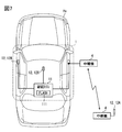
- FIG. 1 is a diagram showing a schematic configuration of an electronic key system for a vehicle.
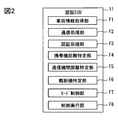
- FIG. 2 is a functional block diagram of the authentication ECU.
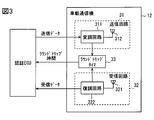
- FIG. 3 is a block diagram showing the configuration of the in-vehicle communication device.
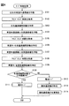
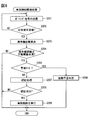
- FIG. 4 is a flowchart for explaining the mode control process.
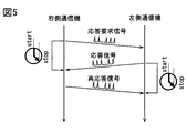
- FIG. 5 is a diagram illustrating a communication mode between in-vehicle communication devices.
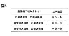
- FIG. 6 is a conceptual diagram of data indicating a normal range for each combination of in-vehicle communication devices.
- FIG. 7 is a diagram illustrating an aspect in which the right-side communication device is removed from the vehicle body and relaying is performed at the baseband level.
- FIG. 8 is a flowchart for explaining vehicle control-related processing.
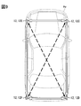
- FIG. 9 is a diagram illustrating a modification of the installation mode of the in-vehicle communication device.
- FIG. 1 is a diagram illustrating an example of a schematic configuration of a vehicle electronic key system 100 of the present disclosure.
- the vehicle electronic key system 100 includes an in-vehicle system 1 mounted on a vehicle Hv and a portable device 2 that is a communication terminal carried by a user of the vehicle Hv.
- the in-vehicle system 1 and the portable device 2 have a configuration for performing two-way wireless communication using radio waves in a predetermined frequency band.
- the in-vehicle system 1 and the portable device 2 are configured to be able to perform wireless communication of Ultra Wide Band-Impulse Radio (UWB-IR) system. That is, the in-vehicle system 1 and the portable device 2 are configured to be able to transmit and receive an impulse-shaped radio wave (hereinafter referred to as an impulse signal) used in UWB communication.
- An impulse signal used in UWB communication is a signal having a pulse width of an extremely short time (for example, 2 ns) and a bandwidth of 500 MHz or more (that is, an ultra-wide bandwidth).
- the UWB band in the present embodiment refers to the 3.1 GHz to 10.6 GHz band as an example. That is, the impulse signal in the present embodiment is realized using radio waves in the 3.1 GHz to 10.6 GHz band.
- the bandwidth of the impulse signal may be 500 MHz or more, and may have a bandwidth of 1.5 GHz or more.
- a modulation method for UWB-IR communication various methods such as a pulse-position modulation (PPM) method in which modulation is performed at a pulse generation position can be adopted.
- PPM pulse-position modulation
- OOK on-off modulation
- PWM pulse width modulation
- PAM pulse amplitude modulation
- PCM pulse code modulation
- the on / off modulation method is a method for expressing information (for example, 0 and 1) by the presence / absence of an impulse signal
- the pulse width modulation method is a method for expressing information by a pulse width.
- the pulse amplitude modulation method is a method for expressing information by the amplitude of an impulse signal.
- the pulse code modulation method is a method for expressing information by a combination of pulses.
- the portable device 2 is configured to return an impulse signal as a response signal when receiving the impulse signal from the in-vehicle system 1.
- the in-vehicle system 1 authenticates the portable device 2 by wirelessly communicating with the portable device 2.
- the in-vehicle system 1 performs predetermined vehicle control for the user to use the vehicle Hv based on the successful authentication of the portable device 2.
- the vehicle control for the user to use the vehicle Hv includes unlocking the vehicle door and starting the engine.
- the process in which the in-vehicle system 1 authenticates the portable device 2 refers to a regular portable device 2 in which a communication terminal that performs wireless communication for the in-vehicle system 1 (hereinafter, communication target) is associated with the in-vehicle system 1. This is a process of confirming that Successful authentication corresponds to the determination that the mobile device 2 is a legitimate portable device 2.
- the authentication of the portable device 2 by the in-vehicle system 1 may be performed by a challenge-response method. Details of the authentication process will be described later.
- a common encryption key used for the authentication process is stored in each of the portable device 2 and the in-vehicle system 1. Further, a unique identification number (hereinafter referred to as a portable device ID) is assigned to the portable device 2, and the portable device ID is registered in the in-vehicle system 1.
- the aforementioned encryption key may be a portable device ID.
- a unique identification number (hereinafter referred to as vehicle ID) is also assigned to the in-vehicle system 1, and the vehicle ID is registered in the portable device 2.
- the portable device 2 can be realized with the aid of communication terminals used for various purposes.
- the portable device 2 includes a portable device-side receiving circuit 21, a portable device-side control unit 22, and a portable device-side transmitting circuit 23.
- the portable device side control unit 22 is connected to each of the portable device side receiving circuit 21 and the portable device side transmitting circuit 23 so as to be communicable.
- the portable device side receiving circuit 21 is configured to receive an impulse signal in the UWB band. When the portable device side receiving circuit 21 receives the impulse signal, the portable device side receiving circuit 21 generates a received signal while performing electrical processing such as demodulating the signal, and outputs the received signal to the portable device side control unit 22.
- the portable device side receiving circuit 21 corresponds to a configuration for receiving a signal from the in-vehicle system 1.
- the portable device side control unit 22 When the reception signal is input from the portable device side receiving circuit 21, the portable device side control unit 22 generates a baseband signal corresponding to the response signal corresponding to this signal, and the baseband signal is transmitted to the portable device side transmission circuit. To 23.
- the portable device side control unit 22 receives a challenge signal, which will be described later, transmitted from the in-vehicle system 1, the baseband signal including a response code generated using an encryption key registered in advance in the portable device 2. Is generated.
- the baseband signal including the response code generated by the portable device side control unit 22 is output to the portable device side transmission circuit 23 and transmitted as a wireless signal.
- the portable device side control unit 22 generates a predetermined response signal when the portable device side reception circuit 21 receives a polling signal (described later) transmitted from the in-vehicle system 1, and cooperates with the portable device side transmission circuit 23. Work and send.
- the portable device side control unit 22 may be realized using a computer including a CPU, a RAM, a ROM, and the like. Note that the portable device-side control unit 22 may be realized using one or a plurality of ICs. In addition, the portable device control unit 22 may be realized using an MPU or a GPU. As will be described later, the portable device-side transmission circuit 23 is configured to convert a baseband signal into an impulse signal and transmit it. Therefore, the portable device side control unit 22 corresponds to a configuration in which the portable device side transmission circuit 23 transmits an impulse signal as a response signal when the portable device side reception circuit 21 receives the impulse signal.
- the portable device side transmission circuit 23 generates a response signal while performing electrical processing, such as modulating the baseband signal input from the portable device side control unit 22, and transmits the response signal by UWB communication.
- the portable device side transmission circuit 23 is configured to transmit a signal to the in-vehicle system 1. Note that it takes a predetermined time (hereinafter, response processing time) from when the portable device 2 receives the impulse signal from the in-vehicle system 1 to when the portable device 2 transmits the impulse signal as the response signal.
- the response processing time is determined according to the hardware configuration of the portable device 2.
- the expected value of the response processing time can be specified in advance by a test or the like.
- the in-vehicle system 1 includes an authentication ECU 11 and a plurality of in-vehicle communication devices 12.
- the authentication ECU 11 is an electronic control unit (ECU) that executes various processes such as a mode control process and a vehicle control process described later.
- the authentication ECU 11 corresponds to an authentication device.
- the authentication ECU 11 is configured as a computer including a CPU, a RAM, a flash memory 111, an I / O, and a bus line that connects these configurations.
- authentication ECU11 may be implement
- the flash memory 111 is a nonvolatile and rewritable memory.
- the flash memory 111 stores a program for causing the computer to function as the authentication ECU 11 (hereinafter, vehicle control program).
- vehicle control program As a specific storage medium for the vehicle control program, various non-transitional physical storage media can be employed. Executing the vehicle control program by the CPU corresponds to executing a method corresponding to the vehicle control program.
- the authentication ECU 11 has a vehicle information acquisition unit F1, a communication processing unit F2, and an authentication processing unit F3 as functions realized by the CPU executing a vehicle control program stored in the flash memory 111.
- the mobile device distance specifying unit F4, the inter-communication device distance specifying unit F5, the leaving device specifying unit F6, the mode control unit F7, and the control execution unit F8 are provided.
- some or all of the various functional blocks included in the authentication ECU 11 may be realized as hardware.
- a mode in which a certain function is realized as hardware includes a mode in which one or a plurality of ICs are used.
- some or all of the various functional blocks may be realized by cooperation of execution of software by a CPU or the like and a hardware configuration.
- the vehicle information acquisition unit F1 acquires various information (hereinafter referred to as vehicle information) indicating the state of the vehicle Hv from sensors or switches mounted on the vehicle Hv.
- vehicle information includes, for example, door open / closed states, door locked / unlocked states, shift positions detected by a shift position sensor, vehicle Hv power state (eg, ignition power on / off), and parking brake operation. State, etc. Note that the types of information included in the vehicle information are not limited to those described above.
- the vehicle information includes a detection result of a brake sensor for detecting whether or not a brake pedal (not shown) is depressed.
- the vehicle information acquisition unit F1 identifies the current state of the vehicle Hv based on the various information described above. For example, the vehicle information acquisition unit F1 determines that the vehicle Hv is parked when the engine is off and all the doors are locked. Of course, the conditions for determining that the vehicle Hv is parked may be appropriately designed, and various determination conditions can be applied. Details of the communication processing unit F2, the authentication processing unit F3, the portable device distance specifying unit F4, the inter-communication device distance specifying unit F5, the leaving machine specifying unit F6, the mode control unit F7, and the control execution unit F8 will be separately described later.
- the authentication ECU 11 is connected to each of the plurality of in-vehicle communication devices 12 so as to be able to communicate with each other via, for example, a dedicated signal line. Note that the authentication ECU 11 may be connected to each of the plurality of in-vehicle communication devices 12 via a communication network built in the vehicle so as to be able to communicate with each other.
- the authentication ECU 11 is also connected to a body ECU and an engine ECU (not shown) so as to be able to communicate with each other via a communication network.
- the body ECU is an ECU that executes various processes related to vehicle body control. For example, the body ECU drives a door lock motor provided in each door based on an instruction from the authentication ECU 11 to lock and unlock each door.
- the engine ECU is an ECU that controls the operation of the engine mounted on the vehicle Hv. For example, when the engine ECU acquires a start instruction signal for instructing start of the engine from the authentication ECU 11, the engine ECU is started.
- the vehicle Hv is a vehicle including an engine as a power source, but is not limited thereto.
- the vehicle Hv may be a so-called hybrid vehicle that includes an engine and a motor as power sources, or may be an electric vehicle that includes only a motor as a power source.
- the authentication ECU 11 of the present embodiment has two types of operation modes, a normal mode and a warning mode, as operation modes.
- the normal mode is an operation mode in which predetermined vehicle control is performed based on the successful authentication of the portable device 2.
- the alert mode is an operation mode in which the execution of the authentication process by wireless communication is canceled (that is, the authentication process is not executed).
- the alert mode may be an operation mode in which vehicle control is not executed even when the authentication of the portable device 2 is successful.
- the in-vehicle communication device 12 is a communication device for performing wireless communication (here, UWB communication) with the portable device 2.
- Each of the plurality of in-vehicle communication devices 12 is configured to be able to perform UWB communication with other in-vehicle communication devices 12 mounted on the vehicle Hv. That is, each in-vehicle communication device 12 is configured to be able to communicate with the portable device 2 and the other in-vehicle communication device 12.
- another in-vehicle communication device 12 for a certain in-vehicle communication device 12 is also referred to as another device.
- the in-vehicle system 1 only needs to include at least two in-vehicle communication devices 12. At least one of the plurality of in-vehicle communication devices 12 is disposed on the outer surface portion of the vehicle Hv.
- the outer surface portion is a body portion that contacts the vehicle exterior space in the vehicle Hv, and includes a side surface portion, a rear surface portion, and a front surface portion of the vehicle Hv.
- the in-vehicle system 1 of this embodiment includes a right communication device 12A, a left communication device 12B, and a vehicle interior communication device 12X as the in-vehicle communication device 12.
- the right communication device 12A is an in-vehicle communication device 12 for forming a communication area mainly on the right side of the vehicle.
- the right communicator 12A is provided in the vicinity of the outer door handle disposed at the front seat door on the right side of the vehicle, for example.
- the outer door handle refers to a gripping member (so-called door handle) provided on the outer surface of the door for opening and closing the door.
- the vicinity of the outer door handle includes the inside of the outer door handle.
- the left communication device 12B is an in-vehicle communication device 12 for forming a communication area mainly on the right side of the vehicle.
- the left communication device 12B is provided on an outer door handle disposed on a front seat door on the left side of the vehicle.
- the in-vehicle communication device 12 arranged on the outer surface portion of the vehicle Hv such as the right communication device 12A and the left communication device 12B is also referred to as an out-of-vehicle communication device.
- the in-vehicle communication device 12X is an in-vehicle communication device 12 for forming a communication area mainly in the entire vehicle interior.
- the vehicle interior communication device 12X is disposed at a position where wireless communication can be performed with the in-vehicle communication device 12 disposed on the outer surface portion of the vehicle Hv, such as the right communication device 12A and the left communication device 12B.
- the vehicle interior communication device 12X is arranged at the center of the ceiling in the vehicle interior.
- the vehicle interior communication device 12X may be disposed on a surface portion on the indoor side of the B pillar. Further, the vehicle interior communication device 12X may be provided in the vehicle width direction center of the instrument panel or in the vicinity of the center console box. Although only one in-vehicle communication device 12X is shown here, a plurality of in-vehicle communication devices 12X may be provided in the vehicle interior.
- the vehicle interior communication device 12X is preferably arranged at a position where the outside of the vehicle interior can be seen so that the radio signal propagates not only inside the vehicle interior but also outside the vehicle interior.
- the vehicle interior communication device 12X can be disposed at any position in the vehicle interior.
- the installation mode (specifically, the installation position and the number of installations) of the in-vehicle communication device 12 is not limited to the above-described mode.
- the vehicle exterior communication device may be disposed on the outer surface of the B pillar of the vehicle Hv.
- the vehicle exterior communication device may be disposed near the boundary between the side surface portion and the roof portion of the vehicle Hv (hereinafter, the side surface upper end portion).
- Such a configuration corresponds to a configuration in which the vehicle exterior communication device is provided in a portion located on the upper side of the side window.
- the upper end portion of the side surface corresponds to a portion where the upper end portion of the door of the vehicle Hv contacts the roof portion of the vehicle Hv.
- the vehicle-mounted system 1 may be provided with the vehicle-mounted communication apparatus 12 which makes the inside of a trunk a communication area, and the vehicle-mounted communication apparatus 12 arrange
- Each vehicle-mounted communication device 12 is set with a unique communication device number.
- the communication device number functions as information for identifying a plurality of in-vehicle communication devices 12.
- the operation of each in-vehicle communication device 12 is controlled by the authentication ECU 11.
- Each of the plurality of in-vehicle communication devices 12 includes a transmission circuit 31, a reception circuit 32, and a round trip timer 33 as shown in FIG.
- the transmission circuit 31 is configured to generate an impulse signal while performing electrical processing, such as modulating a baseband signal input from the authentication ECU 11, and to radiate this impulse signal as a radio wave.
- the transmission circuit 31 is realized using, for example, a modulation circuit 311 and a transmission antenna 312.
- the modulation circuit 311 is a circuit that modulates the baseband signal input from the authentication ECU 11.
- the modulation circuit 311 generates a modulation signal corresponding to data (hereinafter referred to as transmission data) indicated by the baseband signal input from the authentication ECU 11 and transmits the modulation signal to the transmission antenna 312.
- the modulation signal is a signal obtained by modulating transmission data by a predetermined modulation method (for example, PCM modulation method).
- the modulation signal means a signal sequence in which a plurality of impulse signals are arranged at time intervals corresponding to transmission data.
- the modulation circuit 311 includes a circuit that generates an electrical impulse signal (hereinafter referred to as a pulse generation circuit) and a circuit that amplifies and shapes the impulse signal.
- the transmission antenna 312 is configured to convert the electrical impulse signal output from the modulation circuit 311 into a radio wave and radiate it into space. That is, the transmission antenna 312 radiates a pulsed radio wave having a predetermined bandwidth in the UWB band as an impulse signal.
- the modulation circuit 311 simultaneously outputs a signal indicating that the impulse signal has been output (hereinafter, a transmission notification signal) to the round trip timer 33. .
- the transmission circuit 31 of the present embodiment is configured such that the rise time of the impulse signal is 1 ns.
- the rise time is the time required for the signal intensity to exceed 10% of the maximum amplitude for the first time until it exceeds 90% of the maximum amplitude.
- the rise time of the impulse signal is determined according to the hardware configuration such as the circuit configuration of the transmission circuit 31.
- the rise time of the impulse signal can be specified by simulation or actual test. In general, the rise time of an impulse signal in the UWB band is about 1 ns.
- the receiving circuit 32 is a configuration for receiving a radio signal conforming to a communication standard adopted in the vehicle electronic key system 100 such as an impulse signal as a response signal transmitted from the portable device 2.
- the reception circuit 32 includes, for example, a reception antenna 321 and a demodulation circuit 322.
- the receiving antenna 321 is an antenna for receiving an impulse signal.
- the reception antenna 321 outputs an electrical impulse signal corresponding to the impulse signal transmitted by the portable device 2 to the demodulation circuit 322.
- the demodulation circuit 322 When the reception antenna 321 receives the UWB band impulse signal, the demodulation circuit 322 generates a reception signal while performing electrical processing such as demodulating the signal, and outputs the reception signal to the authentication ECU 11. That is, the demodulation circuit 322 is configured to demodulate a series of modulated signals (hereinafter referred to as pulse series signals) composed of a plurality of impulse signals transmitted from the portable device 2 or other devices, and restore the data before modulation. For example, the demodulation circuit 322 acquires a pulse series signal transmitted from the portable device 2 or another in-vehicle communication device 12 based on the impulse signal input from the reception antenna 321.
- pulse series signals composed of a plurality of impulse signals transmitted from the portable device 2 or other devices
- the pulse series signal acquired by the demodulation circuit 322 is a series of a plurality of impulse signals input from the receiving antenna 321 arranged in time series with an actual reception interval.
- the demodulation circuit 322 includes a frequency conversion circuit that converts the frequency of the impulse signal received by the reception antenna 321 into a baseband signal and outputs the signal, an amplification circuit that amplifies the signal level, and the like.
- the reception circuit 32 when an impulse signal is input from the reception antenna 321, the reception circuit 32 outputs a signal indicating that the impulse signal has been received (hereinafter, a reception notification signal) to the round trip timer 33.
- the round trip timer 33 is a timer that measures the time from the transmission circuit 31 transmitting the impulse signal to the reception circuit 32 receiving the impulse signal (hereinafter, round trip time).
- the timing at which the transmission circuit 31 transmits the impulse signal is specified by the input of the transmission notification signal.
- the timing at which the reception circuit 32 receives the impulse signal is specified by the input of the reception notification signal. That is, the round trip timer 33 of this embodiment is configured to measure the time from when the modulation circuit 311 outputs the transmission notification signal until the demodulation circuit 322 outputs the reception notification signal.
- the round trip time corresponds to the signal flight time.
- the round trip timer 33 measures the elapsed time after the transmission circuit 31 transmits the impulse signal by counting the clock signal input from a clock oscillator (not shown). Counting by the round trip timer 33 is stopped when a reception notification signal is input or when a predetermined upper limit value is reached, and the count value is output to the authentication ECU 11. That is, the round trip time is reported to the authentication ECU 11. When reporting of the round trip time to the authentication ECU 11 is completed, the count value of the round trip timer 33 returns to 0 (that is, is reset).
- the mode control process may be executed at a predetermined monitoring period while the vehicle information acquisition unit F1 determines that the vehicle Hv is parked.
- the electric power for the vehicle-mounted system 1 to perform mode control processing should just be supplied from the vehicle-mounted battery which is not shown in figure.
- the monitoring cycle may be appropriately designed such as 500 milliseconds, 1 second, 5 seconds, 1 minute, or the like.
- the communication processing unit F2 operates the right communication device 12A and the left communication device 12B to perform wireless communication in both directions. Specifically, as shown in FIG. 5, the right communication device 12A is caused to transmit a pulse series signal that functions as a response request signal destined for the left communication device 12B. Along with this, the round trip timer 33 of the right communication device 12A starts measuring the elapsed time since the response request signal was transmitted. That is, the round trip time measurement is started.
- the response request signal is a signal for requesting the return of the response signal.
- the response request signal includes, for example, the communication device number of the in-vehicle communication device 12 as the destination (here, the communication device number of the left communication device 12B) as the destination information. By including the destination information in the response request signal, it is possible to prevent the in-vehicle communication device 12 or the portable device 2 other than the destination from returning the response signal. Further, the response request signal includes the communication device number of the in-vehicle communication device 12 that is the transmission source (here, the communication device number of the right communication device 12A) as the transmission source information. When the response request signal includes the transmission source information, the in-vehicle communication device 12 that has received the response request signal can specify the destination of the response signal (in other words, the return destination).
- the left communication device 12B When the left communication device 12B receives the response request signal, it transmits a pulse series signal that functions as a response signal. That is, a response signal designating the transmission source information indicated in the response request signal as a destination is transmitted.
- the response signal also includes destination information and transmission source information.
- the round trip timer 33 of the left communication device 12B starts measuring the elapsed time (that is, the round trip time) since the transmission of the impulse signal with the transmission of the response signal as a trigger.
- the round trip timer 33 of the right communication device 12A stops measuring the round trip time and reports the measured round trip time to the authentication ECU 11.
- the right communication device 12A receives the response signal from the left communication device 12B, the right communication device 12A transmits a re-response signal that is a response signal to the response signal.
- the re-response signal is a pulse series signal that functions as a response signal.
- the re-response signal also includes transmission source information and destination information. Note that the response request signal, the response signal, and the reresponse signal do not need to include destination information and transmission source information, as will be described later separately as Modification 1.
- the response request signal, the response signal, and the reresponse signal may be a single impulse signal.
- the round trip timer 33 of the left communication device 12B When the round trip timer 33 of the left communication device 12B receives the re-response signal from the right communication device 12A, it stops measuring the round trip time and reports the measured round trip time to the authentication ECU 11.
- the round trip time measured by each of the right communication device 12A and the left communication device 12B functions as an index (hereinafter, distance index information) indicating the distance between the right communication device 12A and the left communication device 12B.
- the inter-communication device distance specifying unit F5 acquires the round trip time from each of the right communication device 12A and the left communication device 12B, and proceeds to S103.
- the distance between the left and right communication devices which is the distance between the right communication device 12A and the left communication device 12B, is calculated based on the round trip time acquired in S102.
- the inter-communication distance specifying unit F5 subtracts the estimated value of the response processing time in the left communication device 12B from the round trip time acquired from the right communication device 12A, and further divides the calculated value by two to fly one way. Calculate time. Then, by multiplying the one-way flight time by the propagation speed of radio waves in the air, the distance between the left and right communication devices based on the round trip time acquired from the right communication device 12A is calculated. Further, the inter-communication device distance specifying unit F5 calculates the distance between the left and right communication devices based on the round trip time acquired from the left communication device 12B by the same procedure.
- the distance between the left and right communication devices based on the round trip time acquired from the right communication device 12A and the average value of the distance between the left and right communication devices based on the round trip time acquired from the left communication device 12B are finally determined as the distance between the left and right communication devices.
- the assumed value of the response processing time in the in-vehicle communication device 12 the assumed value of the response processing time in the portable device 2, and the propagation speed of the radio wave are registered in the flash memory 111 as calculation parameters.
- the calculation method of the distance between the left and right communication devices can be changed as appropriate.
- the distance between the left and right communication devices based on the round trip time acquired from the right communication device 12A may be adopted as it is as the final distance between the left and right communication devices.
- the left communication device 12B does not need to measure the round trip time in the first place, and the right communication device 12A does not need to transmit a re-response signal.
- the process in S103 proceeds to S104.
- the communication processing unit F2 activates the vehicle interior communication device 12X and the right communication device 12A, and performs wireless communication in both directions.
- the communication content between the in-vehicle communication device 12X and the right communication device 12A is the same as S101.
- the response request signal may be transmitted from the in-vehicle communication device 12X or may be transmitted from the right communication device 12A.
- the communication processing unit F2 controls the vehicle interior communication device 12X to transmit a response request signal to the right communication device 12A.
- the round trip time representing the distance between the vehicle interior communication device 12X and the right communication device 12A is measured in each of the vehicle interior communication device 12X and the right communication device 12A.
- the inter-communication device distance specifying unit F5 acquires the round trip time from each of the in-vehicle communication device 12X and the right communication device 12A, and proceeds to S106.
- S106 based on the round trip time acquired in S104, the distance between the vehicle interior and the right communication device, which is the distance between the vehicle communication device 12X and the right communication device 12A, is calculated.
- the calculation mode can be the same as the calculation method of the distance between the left and right communication devices. That is, the temporary vehicle interior-right communication device distance is calculated based on the round trip time acquired from the vehicle interior communication device 12X. Further, based on the round trip time acquired from the right communication device 12A, the temporary vehicle interior-right communication device distance is calculated.
- the average value of the distance between the vehicle interior and the right communication device based on the round trip time acquired from the vehicle interior communication device 12X and the distance between the left and right communication devices based on the round trip time acquired from the right communication device 12A is finally obtained. Adopted as the distance between the vehicle interior and the right communication device.
- the communication processing unit F2 operates the vehicle interior communication device 12X and the left communication device 12B, and performs wireless communication in both directions.
- the communication content between the vehicle interior communication device 12X and the left communication device 12B is the same as S101 and S104.
- the response request signal may be transmitted from the in-vehicle communication device 12X or from the left communication device 12B.
- the communication processing unit F2 controls the vehicle interior communication device 12X to transmit a response request signal to the left communication device 12B.
- the round trip time representing the distance between the in-vehicle communication device 12X and the left communication device 12B is measured in each of the in-vehicle communication device 12X and the left communication device 12B.
- the inter-communication device distance specifying unit F5 acquires the round trip time from each of the in-vehicle communication device 12X and the left communication device 12B, and proceeds to S109.
- the distance between the vehicle interior and left communication device which is the distance between the vehicle communication device 12X and the left communication device 12B, is calculated.
- the calculation mode can be the same as the calculation method of the distance between the left and right communication devices described above. That is, based on the round trip time acquired from the vehicle interior communication device 12X, the temporary vehicle interior-left communication device distance is calculated. Further, based on the round trip time acquired from the left communication device 12B, a temporary vehicle interior-left communication device distance is calculated.
- the average value of the distance between the vehicle interior and the left communication device based on the round trip time acquired from the vehicle interior communication device 12X and the distance between the left and right communication devices based on the round trip time acquired from the left communication device 12B is finally obtained.
- the distance between two in-vehicle communication devices 12 disposed at different positions such as the distance between the left and right communication devices, the distance between the vehicle interior and the right communication device, and the distance between the vehicle interior and the left communication device. Also described as the distance between communicators.
- the departure machine specifying unit F6 executes S110.
- the separation machine specifying unit F6 determines whether or not the distances between the various communication devices calculated by the above processing are within a normal range set in advance for each combination of the in-vehicle communication devices 12.
- Data indicating the normal range for each combination of the in-vehicle communication devices 12 (hereinafter, normal range data) is stored in the flash memory 111 as a part of the control execution unit program, for example.
- FIG. 6 is a conceptual diagram showing a configuration of normal range data.
- the normal range according to the combination of the in-vehicle communication devices 12 may be set to a value obtained by adding a distance measurement error to the distance between the in-vehicle communication devices 12 determined by the mounting position of each in-vehicle communication device 12.
- the upper limit value of the normal range corresponds to a threshold value for the authentication ECU 11 to determine that the in-vehicle communication device 12 is removed from the vehicle Hv and relayed at the baseband level.
- the state in which the relay is performed at the baseband level corresponds to a state in which a baseband signal from the authentication ECU 11 to the in-vehicle communication device 12 or a baseband signal from the in-vehicle communication device 12 to the authentication ECU 11 is being relayed. To do.
- the distance between communication devices calculated by the above method is assumed to be 10 m or more.
- the upper limit value of the normal range may be a value larger than the size of the vehicle Hv, such as 5 m or 10 m.
- the lower limit value of the normal range may be set as appropriate, and may be 0 m, for example.
- the normal range may be defined only by the upper limit value.
- S110 If the result of determination in S110 is that there is an inter-communication device distance that deviates from the normal range corresponding to the combination of the in-vehicle communication devices 12 among the multiple inter-communication device distances, S112 is executed. On the other hand, when the distances between the plurality of communication devices are all within the normal range corresponding to the combination of the in-vehicle communication devices 12, S111 is executed.
- the mode control unit F7 sets the operation mode of the authentication ECU 11 to the normal mode and ends this flow.
- the mode control unit F7 sets the operation mode of the authentication ECU 11 to the alert mode, and proceeds to S113.
- the separation machine specifying unit F6 removes the vehicle-mounted communication device that has been removed from the vehicle body based on the combination of the vehicle-mounted communication devices 12 in which the distance between the communication devices is outside the normal range (in other words, an incorrect value). 12 (hereinafter referred to as a vehicle departure machine) is identified.
- the vehicle leaving device is the right communication device 12A.
- the vehicle leaving device can be specified as the left communication device 12B.
- the departure machine specifying unit F6 executes S114.
- the leaving machine specifying unit F6 specifies the position of the vehicle leaving machine based on the distance between at least two communication devices related to the vehicle leaving machine and the installation position of the in-vehicle communication device 12 other than the vehicle leaving machine.
- the inter-communication device distance related to the vehicle leaving machine is the inter-communication machine distance for a combination of in-vehicle communication devices including the vehicle leaving machine. For example, when the vehicle leaving device is the right communication device 12A, the distance between the left and right communication devices and the distance between the vehicle interior and the right communication device correspond to the distance between the communication devices related to the vehicle leaving device.
- the vehicle leaving device is the left communication device 12B, the distance between the left and right communication devices and the distance between the vehicle interior and the left communication device correspond to the distance between the communication devices related to the vehicle departure device.
- the departure device specifying unit F6 includes the distance between the left and right communication devices, the distance between the vehicle interior and the right communication device, the mounting position of the left communication device 12B, and the vehicle interior communication device 12X. Is estimated (e.g., calculated) based on the mounting position of the right communication device 12 ⁇ / b> A as the vehicle departure device. Specifically, it is determined that the right communication device 12A exists at a point that is the distance between the left communication device 12B and the left and right communication devices, and that is the vehicle interior communication device-right communication device distance from the vehicle interior communication device 12X. There are two points that satisfy the above conditions. The departure machine specifying unit F6 may determine that a vehicle departure machine exists at one of the two locations.
- the separation device specifying unit F6 specifies the position of the left communication device 12B as the vehicle release device in the same manner. That is, based on the distance between the left and right communication devices, the distance between the vehicle interior and the left communication device, the mounting position of the right communication device 12A, and the mounting position of the vehicle communication device 12X, the position of the left communication device 12B as the vehicle release device is determined. Identify.
- the in-vehicle system 1 includes four or more in-vehicle communication devices 12 and the number of vehicle leaving devices is one, the number of in-vehicle communication devices (hereinafter, remaining devices) other than the vehicle leaving devices is three. That's it. In other words, there are three or more reference points that can be used for calculating the position of the vehicle leaving machine. When there are at least three reference points that can be used for calculating the position of the vehicle leaving machine, the position of the vehicle leaving machine can be specified in one place.
- the in-vehicle communication device 12 corresponding to the vehicle leaving machine specified by the leaving machine specifying unit F6 and the position information of the vehicle leaving machine may be held in the memory until the operation mode is set to the normal mode.
- the authentication ECU 11 uses the display mounted on the vehicle Hv or the portable device 2 to obtain the position information of the in-vehicle communication device 12 and the vehicle leaving device corresponding to the vehicle leaving device specified by the leaving device specifying unit F6. It may be configured to notify. According to such a configuration, security can be further improved.
- the vehicle control-related process is a process for the authentication ECU 11 to perform vehicle control for the user to use the vehicle Hv based on the result of wireless communication with the portable device 2.
- the vehicle control related process is executed, for example, at a timing when a predetermined time (for example, 10 seconds) has elapsed since the time when the vehicle Hv shifted to the parking state.
- the vehicle control related processing may be configured to be executed sequentially while the vehicle information acquisition unit F1 determines that the vehicle Hv is parked, for example.
- the communication processing unit F2 transmits a polling signal from a predetermined in-vehicle communication device 12 (for example, the in-vehicle communication device 12X), and the process proceeds to S202.
- the polling signal is a wireless signal that does not include a challenge code and requests the portable device 2 to return a response signal. Since the polling signal may play a role of returning the portable device 2 from the sleep mode to the normal mode, the polling signal may be referred to as a wake signal.
- the authentication ECU 11 as the authentication processing unit F3 receives a response signal from the portable device 2 with respect to the polling signal so that a communication terminal that may be the portable device 2 is within the communication area of the vehicle Hv. Can be detected.
- the polling signal includes source information and destination information.
- the round trip timer 33 of the in-vehicle communication device 12 (hereinafter referred to as the working communication device) that is the transmission source of the polling signal starts to measure the elapsed time after transmitting the polling signal. That is, the round trip time measurement is started.
- S202 it is determined whether or not the operating communication device has received a response signal to the polling signal transmitted in S201.
- the operating communication device receives the response signal, an affirmative determination is made in S202, and the process proceeds to S203.
- the round trip timer 33 of the working communication device stops measuring the round trip time and reports the measured round trip time to the authentication ECU 11. This round trip time functions as information indicating the distance from the working communication device to the portable device 2 (hereinafter, portable device distance related information).
- S201 to S202 are processes for transmitting polling signals in order from the plurality of in-vehicle communication devices 12. Note that the order in which the polling signals are transmitted in the plurality of in-vehicle communication devices 12 may be appropriately designed.
- the portable device distance specifying unit F4 calculates the portable device distance that is the distance from the working communication device to the portable device 2 based on the round trip time reported from the working communication device, and proceeds to S204.
- the calculation method of the portable device distance based on the round trip time can be implemented by the same method as the calculation of the distance between communication devices.
- the authentication processing unit F3 determines whether or not the portable device distance calculated in S203 is less than a predetermined operation threshold.
- the operation threshold value corresponds to the upper limit value of the communication device distance that permits execution of vehicle control.
- the operation threshold value is set to a value indicating that the portable device 2 is present in the vicinity of the vehicle Hv or in the vehicle interior, such as 1 m or 2 m, for example. Note that the operating threshold may be set to 5 m.
- the authentication processing unit F3 determines whether or not the operation mode of the authentication ECU 11 is set to the alert mode by the mode control unit F7. When the operation mode of the authentication ECU 11 is set to the alert mode, S206 is executed. On the other hand, when the operation mode of the authentication ECU 11 is set to the normal mode, S207 is executed.
- the authentication processing unit F3 determines that the portable device distance calculated in S203 is an invalid value, and ends this flow. As described above, when the authentication ECU 11 according to the present embodiment determines that the portable device distance is incorrect, the authentication ECU 11 does not perform vehicle control for the user to use the vehicle Hv. If it is determined that the portable device distance is invalid, the vehicle control related process may be executed again from S201.
- the mode control unit F7 sets the operation mode of the authentication ECU 11 to the alert mode
- at least one of the inter-communication device distances for each combination of the in-vehicle communication devices 12 corresponds to the combination of the in-vehicle communication devices 12. This is a case where it deviates from a predetermined normal range.
- such a configuration is such that when at least one of the distances between communication devices for each combination of the in-vehicle communication devices 12 deviates from a predetermined normal range corresponding to the combination of the in-vehicle communication devices 12, the vehicle This corresponds to a configuration in which control is not executed.
- the authentication processing unit F3 executes the authentication processing of the portable device 2 in cooperation with the communication processing unit F2. Specifically, the authentication processing unit F3 requests the communication processing unit F2 to transmit a signal including a challenge code (hereinafter referred to as a challenge signal) from the operating communication device. The communication processing unit F2 transmits a challenge signal from the working communication device based on the request from the authentication processing unit F3.
- a challenge signal a challenge code
- the challenge code is a code for authenticating the portable device 2.
- the challenge code may be a random number generated using a random number table or the like.
- the portable device 2 encrypts the challenge code using an encryption key registered in advance in the portable device 2, and a signal including the encrypted code (hereinafter, response code) (hereinafter, response code). Response signal).
- the authentication processing unit F3 transmits a challenge signal and generates a code (hereinafter referred to as a verification code) obtained by encrypting the challenge code using an encryption key held by itself.
- S208 it is determined whether or not the authentication process is successful. For example, if the response signal can be received from the portable device 2 and the response code indicated in the response signal matches the verification code, it is determined that the authentication is successful. On the other hand, if the response code cannot be received even after the response waiting time has elapsed since the challenge signal was transmitted, it is determined that the authentication has failed. Even if the response code can be received, if the response code indicated by the response signal does not match the verification code, it is determined that the authentication has failed.
- the control execution unit F8 executes predetermined vehicle control for the user to use the vehicle Hv according to the scene when the authentication process is successful (in other words, the state of the vehicle Hv). For example, when the vehicle Hv is parked, the control execution unit F8 sets the door lock mechanism of the vehicle Hv to an unlocked state or a venue preparation state in cooperation with a body ECU (not shown).
- the venue preparation state is a state in which the user can unlock the door only by touching a button or a touch sensor arranged on the door.
- the control execution unit F8 starts the engine in cooperation with the engine ECU.
- the content of the vehicle control performed by the control execution unit F8 is appropriately determined according to the scene when the authentication process is successful (in other words, the state of the vehicle Hv).
- the authentication ECU 11 performs bidirectional wireless communication for each combination of the in-vehicle communication devices 12 in a positional relationship capable of wireless communication with each other, and based on the round trip time obtained as a result of the communication, It is determined whether the distance is a normal value.
- execution of vehicle control such as unlocking the vehicle door is performed. Is prohibited (or put on hold).
- the in-vehicle communication device 12 arranged on the outer surface portion of the vehicle Hv is removed from the vehicle Hv together with the module, and the relay at the baseband signal level is performed.
- the fear that the vehicle Hv is illegally used can be suppressed.
- a mode in which execution of vehicle control is prohibited by regarding the mobile device distance specified by the mobile device distance specifying unit F4 as an illegal value has been disclosed.
- the configuration in which vehicle control is not executed when there is a distance between communication devices that deviates from the normal range according to the combination of the in-vehicle communication devices 12 among the plurality of communication device distances is not limited thereto.
- the authentication process may not be executed. good. If the authentication process is not executed, the authentication is not successful. Therefore, execution of vehicle control can be prohibited also by the above configuration.
- a polling signal or the like is directed to the portable device 2
- You may be comprised so that transmission of a signal may be stopped. Also with the above configuration, execution of vehicle control can be prohibited.
- ⁇ Modification 1> when specifying the distance between the communication devices, a mode in which the two in-vehicle communication devices 12 to be distance-measuring exchange signals including the transmission source information and the destination information is disclosed, but the present invention is not limited thereto.
- the in-vehicle communication device 12 may be configured to measure the round trip time by transmitting and receiving a single impulse signal.
- the in-vehicle communication device 12 transmits a single impulse signal as a response request signal based on an instruction from the authentication ECU 11. Moreover, the two vehicle-mounted communication apparatuses 12 which provide the combination made into a ranging object return a single impulse signal as a response signal and a reresponse signal, when a single impulse signal is received.
- the authentication ECU 11 in this modification controls the vehicle-mounted communication devices 12 other than the combinations to be distance-measured to stop the operation or not to return a single pulse signal as a response signal even if a single pulse signal is received. Is done. For example, while the processing for measuring the distance between the left and right communication devices is being performed in S101 to S103, the vehicle interior communication device 12X stops its operation.
- the state in which the vehicle-mounted communication device 12 has stopped operating is a state in which signal transmission / reception is not performed.
- the portable device 2 of the present modification is also configured not to return a single pulse signal as a response signal even when a single impulse signal is received.
- the round trip time includes the time required for the arithmetic processing for generating the response signal (that is, the response processing time). It becomes difficult. As a result, it is possible to improve the distance measurement accuracy of the distance between the communication devices.
- ⁇ Modification 2> a mode in which the distance between communication devices is calculated using the round trip time is disclosed, but the index for calculating the distance between communication devices is not limited to the round trip time.
- Each in-vehicle communication device 12 reports the reception intensity of the signal transmitted from the other device to the authentication ECU 11 as distance index information, and the inter-communication device distance specifying unit F5 is based on the reception intensity detected by each in-vehicle communication device 12. You may be comprised so that the distance between communication apparatuses may be calculated.
- each in-vehicle communication device 12 may be configured to generate a one-way flight time as distance index information.
- the one-way flight time is the difference between the time when the other aircraft transmits a signal and the time when the signal is actually received.
- the one-way flight time can be calculated by predefining the time at which each in-vehicle communication device 12 transmits a signal.
- various methods can be used as a method of calculating the distance between communication devices.
- each vehicle-mounted communication device 12 reports the round trip time to the authentication ECU 11, and the authentication ECU 11 calculates the distance between the communication devices based on the round trip time provided from each vehicle-mounted communication device 12.
- Each in-vehicle communication device 12 may have a function of calculating the distance between communication devices based on the round trip time. That is, each in-vehicle communication device 12 calculates the distance from its own device to the other device as a communication partner based on the round trip time measured when wirelessly communicating with the other device. And the data which show the said distance are matched with the communication apparatus number about each of a communicating party and an own machine, and are reported to authentication ECU11.
- each in-vehicle communication device 12 may be configured to calculate a distance based on the reception intensity of a signal received from another device.
- the data indicating the round trip time generated by the in-vehicle communication device 12 and the data indicating the reception intensity correspond to distance-related information that indirectly indicates the distance to the other device.
- the data indicating the distance corresponds to the distance related information that directly indicates the distance to the other device.
- the aspect provided with the vehicle interior communication apparatus 12X was disclosed, it is not restricted to this.
- the vehicle interior communication device 12X may not be provided.
- all the in-vehicle communication devices 12 may be arranged on the outer surface portion of the vehicle Hv.
- the in-vehicle system 1 may be arranged in the four corners of the vehicle Hv.
- the in-vehicle communication device 12C shown in FIG. 9 is the in-vehicle communication device 12 disposed in the right corner portion at the front end of the vehicle.
- the in-vehicle communication device 12D is the in-vehicle communication device 12 disposed in the right corner portion at the rear end of the vehicle.
- the in-vehicle communication device 12E is the in-vehicle communication device 12 disposed in the left corner portion at the front end of the vehicle.
- the in-vehicle communication device 12F is the in-vehicle communication device 12 disposed in the left corner portion at the rear end of the vehicle.
- the authentication ECU 11 is not shown.
- white arrows in FIG. 9 indicate combinations of the in-vehicle communication devices 12 configured to be able to communicate with each other wirelessly. As shown in FIG. 9, it may be configured not to / cannot perform wireless communication with the vehicle-mounted communication device 12 positioned diagonally.
- Each in-vehicle communication device 12 may be configured to be capable of wireless communication with at least one other device.
- the combination of the in-vehicle communication devices 12 to be used for calculating the distance between the communication devices may be designed as appropriate.
- each of the in-vehicle communication devices 12C to 12F may be configured to be able to perform wireless communication with other devices existing at diagonal positions as indicated by broken line arrows.
- the in-vehicle system 1 and the portable device 2 disclose a configuration in which wireless communication is performed by the Impulse Radio method, but is not limited thereto.
- the in-vehicle system 1 and the portable device 2 may be configured to perform wireless communication by a MultiBand Orthogonal Frequency Division Multiplexing (MB-OFDM) method, a Direct Sequence UWB (DS-UWB) method, or the like.
- the in-vehicle system 1 and the portable device 2 are connected to each other by wireless communication (hereinafter, short-range communication) compliant with a short-range wireless communication standard such as Bluetooth (registered trademark), Wi-Fi (registered trademark), or ZigBee (registered trademark). ) May be implemented. You may be comprised so that wireless communication may be implemented using the radio wave of LF band, and the radio wave of UHF band.
- the means and / or function provided by the authentication ECU 11 can be provided by software recorded in a substantial memory device and a computer that executes the software, only software, only hardware, or a combination thereof.
- the authentication ECU 11 when it is provided by an electronic circuit that is hardware, it can be provided by a digital circuit including a large number of logic circuits, or an analog circuit. Further, the authentication ECU 11 can be provided by one computer or a set of computer resources configured to be able to communicate with each other.
- the portable device 2 may be any device that is carried by the user and has a function as an electronic key of the vehicle Hv.
- the function as the electronic key of the vehicle Hv is specifically a function of transmitting a signal (for example, a response signal) including information proving that the key is the vehicle Hv based on a request from the in-vehicle system 1.
- the portable device 2 may be a rectangular, elliptical (fob type), or card-type small device conventionally known as a smart key.
- the portable device 2 may be configured as a wearable device that is worn on a user's finger or arm.
- the portable device 2 may be an information processing terminal such as a smartphone or a tablet terminal.
Landscapes
- Engineering & Computer Science (AREA)
- Radar, Positioning & Navigation (AREA)
- Remote Sensing (AREA)
- Computer Networks & Wireless Communication (AREA)
- Physics & Mathematics (AREA)
- General Physics & Mathematics (AREA)
- Mechanical Engineering (AREA)
- Lock And Its Accessories (AREA)
- Radar Systems Or Details Thereof (AREA)
Priority Applications (3)
| Application Number | Priority Date | Filing Date | Title |
|---|---|---|---|
| CN201980023656.6A CN111989448A (zh) | 2018-04-09 | 2019-02-14 | 车辆用电子钥匙系统 |
| DE112019001846.9T DE112019001846T5 (de) | 2018-04-09 | 2019-02-14 | Elektronisches fahrzeugschlüsselsystem |
| US17/063,915 US11208074B2 (en) | 2018-04-09 | 2020-10-06 | Vehicle electronic key system |
Applications Claiming Priority (2)
| Application Number | Priority Date | Filing Date | Title |
|---|---|---|---|
| JP2018-074743 | 2018-04-09 | ||
| JP2018074743A JP7003820B2 (ja) | 2018-04-09 | 2018-04-09 | 車両用電子キーシステム |
Related Child Applications (1)
| Application Number | Title | Priority Date | Filing Date |
|---|---|---|---|
| US17/063,915 Continuation US11208074B2 (en) | 2018-04-09 | 2020-10-06 | Vehicle electronic key system |
Publications (1)
| Publication Number | Publication Date |
|---|---|
| WO2019198331A1 true WO2019198331A1 (ja) | 2019-10-17 |
Family
ID=68163997
Family Applications (1)
| Application Number | Title | Priority Date | Filing Date |
|---|---|---|---|
| PCT/JP2019/005331 Ceased WO2019198331A1 (ja) | 2018-04-09 | 2019-02-14 | 車両用電子キーシステム |
Country Status (5)
| Country | Link |
|---|---|
| US (1) | US11208074B2 (enExample) |
| JP (1) | JP7003820B2 (enExample) |
| CN (1) | CN111989448A (enExample) |
| DE (1) | DE112019001846T5 (enExample) |
| WO (1) | WO2019198331A1 (enExample) |
Cited By (4)
| Publication number | Priority date | Publication date | Assignee | Title |
|---|---|---|---|---|
| WO2020158308A1 (ja) * | 2019-01-31 | 2020-08-06 | 株式会社デンソー | 車両用位置推定システム |
| CN112839322A (zh) * | 2019-11-01 | 2021-05-25 | 株式会社东海理化电机制作所 | 通信装置和系统 |
| WO2023063276A1 (ja) * | 2021-10-13 | 2023-04-20 | 株式会社デンソー | 位置判定システム、位置判定方法 |
| WO2024202150A1 (ja) * | 2023-03-29 | 2024-10-03 | 株式会社東海理化電機製作所 | 判定システム、判定方法、および判定装置 |
Families Citing this family (19)
| Publication number | Priority date | Publication date | Assignee | Title |
|---|---|---|---|---|
| JP7082012B2 (ja) | 2018-08-23 | 2022-06-07 | 株式会社東海理化電機製作所 | 通信不正成立防止システム及び通信不正成立防止方法 |
| KR102751281B1 (ko) * | 2019-07-04 | 2025-01-10 | 현대자동차주식회사 | 차량의 스마트 엔트리 시스템 및 그 동작 방법 |
| JP2021028583A (ja) * | 2019-08-09 | 2021-02-25 | 株式会社東海理化電機製作所 | 制御装置およびプログラム |
| JP7383962B2 (ja) * | 2019-10-04 | 2023-11-21 | 株式会社三洋物産 | 遊技機 |
| JP7383964B2 (ja) * | 2019-10-04 | 2023-11-21 | 株式会社三洋物産 | 遊技機 |
| JP7383961B2 (ja) * | 2019-10-04 | 2023-11-21 | 株式会社三洋物産 | 遊技機 |
| JP7383963B2 (ja) * | 2019-10-04 | 2023-11-21 | 株式会社三洋物産 | 遊技機 |
| JP2021141427A (ja) * | 2020-03-05 | 2021-09-16 | 株式会社東海理化電機製作所 | 通信装置、端末装置、及び無線信号のデータ構造 |
| JP7382280B2 (ja) * | 2020-05-25 | 2023-11-16 | 株式会社東海理化電機製作所 | 制御装置および制御方法 |
| JP7382281B2 (ja) * | 2020-05-25 | 2023-11-16 | 株式会社東海理化電機製作所 | 制御装置および制御方法 |
| JP2021188924A (ja) * | 2020-05-26 | 2021-12-13 | 株式会社東海理化電機製作所 | 制御装置およびプログラム |
| JP2021188446A (ja) * | 2020-06-03 | 2021-12-13 | 株式会社東海理化電機製作所 | 筐体装置およびシステム |
| JP7446926B2 (ja) | 2020-06-05 | 2024-03-11 | 株式会社東海理化電機製作所 | 制御装置および制御方法 |
| JP7414648B2 (ja) * | 2020-06-05 | 2024-01-16 | 株式会社東海理化電機製作所 | 制御装置および制御方法 |
| JP7116761B2 (ja) * | 2020-07-27 | 2022-08-10 | 本田技研工業株式会社 | 車両制御システム、車両制御方法、及び車両制御サーバー |
| DE102020209650A1 (de) * | 2020-07-30 | 2022-02-03 | Volkswagen Aktiengesellschaft | Verfahren zum Erfassen von Personen und/oder Objekten im Innenraum eines Kraftfahrzeugs und Kraftfahrzeug |
| CN114698197A (zh) * | 2020-12-31 | 2022-07-01 | 常州星宇车灯股份有限公司 | 场景自适应的灯具控制系统 |
| JP7334751B2 (ja) * | 2021-02-24 | 2023-08-29 | トヨタ自動車株式会社 | 情報処理装置、情報処理方法、及び、システム |
| JP2022180087A (ja) * | 2021-05-24 | 2022-12-06 | 株式会社東海理化電機製作所 | 通信装置、プログラム、およびシステム |
Citations (3)
| Publication number | Priority date | Publication date | Assignee | Title |
|---|---|---|---|---|
| JP2005005902A (ja) * | 2003-06-10 | 2005-01-06 | Toshiba Corp | 通信装置、携帯端末装置、通信システム、通信制御プログラム及び通信制御方法 |
| US20170318423A1 (en) * | 2016-04-27 | 2017-11-02 | Continental Automotive Gmbh | Transmitter And/Or Receiver Units |
| JP2018031601A (ja) * | 2016-08-22 | 2018-03-01 | 株式会社デンソー | 距離推定システム |
Family Cites Families (9)
| Publication number | Priority date | Publication date | Assignee | Title |
|---|---|---|---|---|
| JP3693725B2 (ja) * | 1995-11-24 | 2005-09-07 | 株式会社日本自動車部品総合研究所 | トランスポンダを用いた自動応答システム |
| DE102008012606B4 (de) * | 2008-03-05 | 2019-07-04 | Continental Automotive Gmbh | Passives drahtloses Zugangssystem mit einem Ortungssystem und Verfahren zum Herstellen und Betreiben des Systems |
| JP5667038B2 (ja) * | 2011-12-21 | 2015-02-12 | 株式会社東海理化電機製作所 | 車両の電子キーシステム |
| JP6093647B2 (ja) | 2013-05-17 | 2017-03-08 | 株式会社東海理化電機製作所 | 電子キーシステム |
| JP6205237B2 (ja) * | 2013-10-25 | 2017-09-27 | Kddi株式会社 | 距離測定システム |
| JP6137687B2 (ja) * | 2013-12-12 | 2017-05-31 | アルプス電気株式会社 | キーレスエントリーシステム |
| JP6354165B2 (ja) | 2014-01-15 | 2018-07-11 | 株式会社デンソー | 制御システム |
| JP6334311B2 (ja) | 2014-08-08 | 2018-05-30 | 株式会社東海理化電機製作所 | 距離測定システム |
| JP6363437B2 (ja) | 2014-09-05 | 2018-07-25 | 株式会社東海理化電機製作所 | 電子キーシステム |
-
2018
- 2018-04-09 JP JP2018074743A patent/JP7003820B2/ja active Active
-
2019
- 2019-02-14 DE DE112019001846.9T patent/DE112019001846T5/de active Pending
- 2019-02-14 CN CN201980023656.6A patent/CN111989448A/zh active Pending
- 2019-02-14 WO PCT/JP2019/005331 patent/WO2019198331A1/ja not_active Ceased
-
2020
- 2020-10-06 US US17/063,915 patent/US11208074B2/en active Active
Patent Citations (3)
| Publication number | Priority date | Publication date | Assignee | Title |
|---|---|---|---|---|
| JP2005005902A (ja) * | 2003-06-10 | 2005-01-06 | Toshiba Corp | 通信装置、携帯端末装置、通信システム、通信制御プログラム及び通信制御方法 |
| US20170318423A1 (en) * | 2016-04-27 | 2017-11-02 | Continental Automotive Gmbh | Transmitter And/Or Receiver Units |
| JP2018031601A (ja) * | 2016-08-22 | 2018-03-01 | 株式会社デンソー | 距離推定システム |
Cited By (7)
| Publication number | Priority date | Publication date | Assignee | Title |
|---|---|---|---|---|
| WO2020158308A1 (ja) * | 2019-01-31 | 2020-08-06 | 株式会社デンソー | 車両用位置推定システム |
| JP2020122725A (ja) * | 2019-01-31 | 2020-08-13 | 株式会社Soken | 車両用位置推定システム |
| JP7183829B2 (ja) | 2019-01-31 | 2022-12-06 | 株式会社Soken | 車両用位置推定システム |
| CN112839322A (zh) * | 2019-11-01 | 2021-05-25 | 株式会社东海理化电机制作所 | 通信装置和系统 |
| WO2023063276A1 (ja) * | 2021-10-13 | 2023-04-20 | 株式会社デンソー | 位置判定システム、位置判定方法 |
| JP2023058256A (ja) * | 2021-10-13 | 2023-04-25 | 株式会社デンソー | 位置判定システム、位置判定方法 |
| WO2024202150A1 (ja) * | 2023-03-29 | 2024-10-03 | 株式会社東海理化電機製作所 | 判定システム、判定方法、および判定装置 |
Also Published As
| Publication number | Publication date |
|---|---|
| JP7003820B2 (ja) | 2022-01-21 |
| US11208074B2 (en) | 2021-12-28 |
| DE112019001846T5 (de) | 2020-12-24 |
| CN111989448A (zh) | 2020-11-24 |
| JP2019183487A (ja) | 2019-10-24 |
| US20210016743A1 (en) | 2021-01-21 |
Similar Documents
| Publication | Publication Date | Title |
|---|---|---|
| JP7003820B2 (ja) | 車両用電子キーシステム | |
| JP7183830B2 (ja) | 車両用位置推定システム | |
| US11320513B2 (en) | Portable device position estimation system | |
| US11084460B2 (en) | Method for activation of at least one security function of a security system of a vehicle | |
| JP7601157B2 (ja) | デジタルキーシステム | |
| US10906508B2 (en) | Method for activating at least one security function of a security system of a vehicle | |
| US10902690B2 (en) | Method for activating of at least one security function of a security system of a vehicle | |
| US12269480B2 (en) | Vehicular position estimation system | |
| JP6451441B2 (ja) | ユーザ識別システム、車両用携帯機 | |
| JP2018107653A (ja) | 車両用認証システム | |
| WO2019225320A1 (ja) | 車両用認証装置 | |
| US20240336226A1 (en) | Position determination device, position determination method, and vehicular electronic key system | |
| JP2020122726A (ja) | 車両用位置推定システム | |
| JP7380156B2 (ja) | 携帯端末距離推定システムおよび車載システム | |
| WO2021192598A1 (ja) | 距離推定装置 | |
| WO2023228779A1 (ja) | 車両制御システム、車両制御プログラム、位置確認装置 | |
| JP2020088436A (ja) | 位置判定システム及び位置判定システムの制御方法 | |
| JP2023177066A (ja) | 車両用位置判定装置、車両用位置判定システム、位置判定方法 | |
| JP2024082996A (ja) | 位置判定装置、位置判定システム、無線通信モジュール、コンピュータプログラム | |
| JP2025037649A (ja) | 位置判定システム、位置判定方法 |
Legal Events
| Date | Code | Title | Description |
|---|---|---|---|
| 121 | Ep: the epo has been informed by wipo that ep was designated in this application |
Ref document number: 19784446 Country of ref document: EP Kind code of ref document: A1 |
|
| 122 | Ep: pct application non-entry in european phase |
Ref document number: 19784446 Country of ref document: EP Kind code of ref document: A1 |