WO2019189582A1 - Procédé de fabrication d'un article moulé - Google Patents
Procédé de fabrication d'un article moulé Download PDFInfo
- Publication number
- WO2019189582A1 WO2019189582A1 PCT/JP2019/013619 JP2019013619W WO2019189582A1 WO 2019189582 A1 WO2019189582 A1 WO 2019189582A1 JP 2019013619 W JP2019013619 W JP 2019013619W WO 2019189582 A1 WO2019189582 A1 WO 2019189582A1
- Authority
- WO
- WIPO (PCT)
- Prior art keywords
- porous body
- decorative layer
- molded product
- producing
- resin
- Prior art date
Links
Images


Classifications
-
- B—PERFORMING OPERATIONS; TRANSPORTING
- B29—WORKING OF PLASTICS; WORKING OF SUBSTANCES IN A PLASTIC STATE IN GENERAL
- B29C—SHAPING OR JOINING OF PLASTICS; SHAPING OF MATERIAL IN A PLASTIC STATE, NOT OTHERWISE PROVIDED FOR; AFTER-TREATMENT OF THE SHAPED PRODUCTS, e.g. REPAIRING
- B29C51/00—Shaping by thermoforming, i.e. shaping sheets or sheet like preforms after heating, e.g. shaping sheets in matched moulds or by deep-drawing; Apparatus therefor
- B29C51/02—Combined thermoforming and manufacture of the preform
-
- B—PERFORMING OPERATIONS; TRANSPORTING
- B29—WORKING OF PLASTICS; WORKING OF SUBSTANCES IN A PLASTIC STATE IN GENERAL
- B29B—PREPARATION OR PRETREATMENT OF THE MATERIAL TO BE SHAPED; MAKING GRANULES OR PREFORMS; RECOVERY OF PLASTICS OR OTHER CONSTITUENTS OF WASTE MATERIAL CONTAINING PLASTICS
- B29B15/00—Pretreatment of the material to be shaped, not covered by groups B29B7/00 - B29B13/00
- B29B15/08—Pretreatment of the material to be shaped, not covered by groups B29B7/00 - B29B13/00 of reinforcements or fillers
- B29B15/10—Coating or impregnating independently of the moulding or shaping step
- B29B15/12—Coating or impregnating independently of the moulding or shaping step of reinforcements of indefinite length
- B29B15/14—Coating or impregnating independently of the moulding or shaping step of reinforcements of indefinite length of filaments or wires
-
- B—PERFORMING OPERATIONS; TRANSPORTING
- B29—WORKING OF PLASTICS; WORKING OF SUBSTANCES IN A PLASTIC STATE IN GENERAL
- B29C—SHAPING OR JOINING OF PLASTICS; SHAPING OF MATERIAL IN A PLASTIC STATE, NOT OTHERWISE PROVIDED FOR; AFTER-TREATMENT OF THE SHAPED PRODUCTS, e.g. REPAIRING
- B29C43/00—Compression moulding, i.e. applying external pressure to flow the moulding material; Apparatus therefor
- B29C43/02—Compression moulding, i.e. applying external pressure to flow the moulding material; Apparatus therefor of articles of definite length, i.e. discrete articles
- B29C43/18—Compression moulding, i.e. applying external pressure to flow the moulding material; Apparatus therefor of articles of definite length, i.e. discrete articles incorporating preformed parts or layers, e.g. compression moulding around inserts or for coating articles
- B29C43/183—Compression moulding, i.e. applying external pressure to flow the moulding material; Apparatus therefor of articles of definite length, i.e. discrete articles incorporating preformed parts or layers, e.g. compression moulding around inserts or for coating articles the preformed layer being a lining, e.g. shaped in the mould before compression moulding, or a preformed shell adapted to the shape of the mould
-
- B—PERFORMING OPERATIONS; TRANSPORTING
- B29—WORKING OF PLASTICS; WORKING OF SUBSTANCES IN A PLASTIC STATE IN GENERAL
- B29C—SHAPING OR JOINING OF PLASTICS; SHAPING OF MATERIAL IN A PLASTIC STATE, NOT OTHERWISE PROVIDED FOR; AFTER-TREATMENT OF THE SHAPED PRODUCTS, e.g. REPAIRING
- B29C51/00—Shaping by thermoforming, i.e. shaping sheets or sheet like preforms after heating, e.g. shaping sheets in matched moulds or by deep-drawing; Apparatus therefor
- B29C51/18—Thermoforming apparatus
- B29C51/20—Thermoforming apparatus having movable moulds or mould parts
-
- B—PERFORMING OPERATIONS; TRANSPORTING
- B29—WORKING OF PLASTICS; WORKING OF SUBSTANCES IN A PLASTIC STATE IN GENERAL
- B29C—SHAPING OR JOINING OF PLASTICS; SHAPING OF MATERIAL IN A PLASTIC STATE, NOT OTHERWISE PROVIDED FOR; AFTER-TREATMENT OF THE SHAPED PRODUCTS, e.g. REPAIRING
- B29C51/00—Shaping by thermoforming, i.e. shaping sheets or sheet like preforms after heating, e.g. shaping sheets in matched moulds or by deep-drawing; Apparatus therefor
- B29C51/26—Component parts, details or accessories; Auxiliary operations
- B29C51/42—Heating or cooling
- B29C51/421—Heating or cooling of preforms, specially adapted for thermoforming
- B29C51/425—Heating or cooling of preforms, specially adapted for thermoforming using movable heating devices
-
- B—PERFORMING OPERATIONS; TRANSPORTING
- B29—WORKING OF PLASTICS; WORKING OF SUBSTANCES IN A PLASTIC STATE IN GENERAL
- B29C—SHAPING OR JOINING OF PLASTICS; SHAPING OF MATERIAL IN A PLASTIC STATE, NOT OTHERWISE PROVIDED FOR; AFTER-TREATMENT OF THE SHAPED PRODUCTS, e.g. REPAIRING
- B29C65/00—Joining or sealing of preformed parts, e.g. welding of plastics materials; Apparatus therefor
- B29C65/02—Joining or sealing of preformed parts, e.g. welding of plastics materials; Apparatus therefor by heating, with or without pressure
-
- B—PERFORMING OPERATIONS; TRANSPORTING
- B29—WORKING OF PLASTICS; WORKING OF SUBSTANCES IN A PLASTIC STATE IN GENERAL
- B29C—SHAPING OR JOINING OF PLASTICS; SHAPING OF MATERIAL IN A PLASTIC STATE, NOT OTHERWISE PROVIDED FOR; AFTER-TREATMENT OF THE SHAPED PRODUCTS, e.g. REPAIRING
- B29C67/00—Shaping techniques not covered by groups B29C39/00 - B29C65/00, B29C70/00 or B29C73/00
- B29C67/20—Shaping techniques not covered by groups B29C39/00 - B29C65/00, B29C70/00 or B29C73/00 for porous or cellular articles, e.g. of foam plastics, coarse-pored
-
- B—PERFORMING OPERATIONS; TRANSPORTING
- B29—WORKING OF PLASTICS; WORKING OF SUBSTANCES IN A PLASTIC STATE IN GENERAL
- B29C—SHAPING OR JOINING OF PLASTICS; SHAPING OF MATERIAL IN A PLASTIC STATE, NOT OTHERWISE PROVIDED FOR; AFTER-TREATMENT OF THE SHAPED PRODUCTS, e.g. REPAIRING
- B29C70/00—Shaping composites, i.e. plastics material comprising reinforcements, fillers or preformed parts, e.g. inserts
- B29C70/04—Shaping composites, i.e. plastics material comprising reinforcements, fillers or preformed parts, e.g. inserts comprising reinforcements only, e.g. self-reinforcing plastics
- B29C70/06—Fibrous reinforcements only
-
- B—PERFORMING OPERATIONS; TRANSPORTING
- B29—WORKING OF PLASTICS; WORKING OF SUBSTANCES IN A PLASTIC STATE IN GENERAL
- B29B—PREPARATION OR PRETREATMENT OF THE MATERIAL TO BE SHAPED; MAKING GRANULES OR PREFORMS; RECOVERY OF PLASTICS OR OTHER CONSTITUENTS OF WASTE MATERIAL CONTAINING PLASTICS
- B29B13/00—Conditioning or physical treatment of the material to be shaped
- B29B13/02—Conditioning or physical treatment of the material to be shaped by heating
- B29B13/023—Half-products, e.g. films, plates
-
- B—PERFORMING OPERATIONS; TRANSPORTING
- B29—WORKING OF PLASTICS; WORKING OF SUBSTANCES IN A PLASTIC STATE IN GENERAL
- B29C—SHAPING OR JOINING OF PLASTICS; SHAPING OF MATERIAL IN A PLASTIC STATE, NOT OTHERWISE PROVIDED FOR; AFTER-TREATMENT OF THE SHAPED PRODUCTS, e.g. REPAIRING
- B29C43/00—Compression moulding, i.e. applying external pressure to flow the moulding material; Apparatus therefor
- B29C43/02—Compression moulding, i.e. applying external pressure to flow the moulding material; Apparatus therefor of articles of definite length, i.e. discrete articles
- B29C43/18—Compression moulding, i.e. applying external pressure to flow the moulding material; Apparatus therefor of articles of definite length, i.e. discrete articles incorporating preformed parts or layers, e.g. compression moulding around inserts or for coating articles
- B29C43/183—Compression moulding, i.e. applying external pressure to flow the moulding material; Apparatus therefor of articles of definite length, i.e. discrete articles incorporating preformed parts or layers, e.g. compression moulding around inserts or for coating articles the preformed layer being a lining, e.g. shaped in the mould before compression moulding, or a preformed shell adapted to the shape of the mould
- B29C43/184—Compression moulding, i.e. applying external pressure to flow the moulding material; Apparatus therefor of articles of definite length, i.e. discrete articles incorporating preformed parts or layers, e.g. compression moulding around inserts or for coating articles the preformed layer being a lining, e.g. shaped in the mould before compression moulding, or a preformed shell adapted to the shape of the mould shaped by the compression of the material during moulding
-
- B—PERFORMING OPERATIONS; TRANSPORTING
- B29—WORKING OF PLASTICS; WORKING OF SUBSTANCES IN A PLASTIC STATE IN GENERAL
- B29C—SHAPING OR JOINING OF PLASTICS; SHAPING OF MATERIAL IN A PLASTIC STATE, NOT OTHERWISE PROVIDED FOR; AFTER-TREATMENT OF THE SHAPED PRODUCTS, e.g. REPAIRING
- B29C51/00—Shaping by thermoforming, i.e. shaping sheets or sheet like preforms after heating, e.g. shaping sheets in matched moulds or by deep-drawing; Apparatus therefor
- B29C51/002—Shaping by thermoforming, i.e. shaping sheets or sheet like preforms after heating, e.g. shaping sheets in matched moulds or by deep-drawing; Apparatus therefor characterised by the choice of material
-
- B—PERFORMING OPERATIONS; TRANSPORTING
- B29—WORKING OF PLASTICS; WORKING OF SUBSTANCES IN A PLASTIC STATE IN GENERAL
- B29C—SHAPING OR JOINING OF PLASTICS; SHAPING OF MATERIAL IN A PLASTIC STATE, NOT OTHERWISE PROVIDED FOR; AFTER-TREATMENT OF THE SHAPED PRODUCTS, e.g. REPAIRING
- B29C51/00—Shaping by thermoforming, i.e. shaping sheets or sheet like preforms after heating, e.g. shaping sheets in matched moulds or by deep-drawing; Apparatus therefor
- B29C51/08—Deep drawing or matched-mould forming, i.e. using mechanical means only
-
- B—PERFORMING OPERATIONS; TRANSPORTING
- B29—WORKING OF PLASTICS; WORKING OF SUBSTANCES IN A PLASTIC STATE IN GENERAL
- B29C—SHAPING OR JOINING OF PLASTICS; SHAPING OF MATERIAL IN A PLASTIC STATE, NOT OTHERWISE PROVIDED FOR; AFTER-TREATMENT OF THE SHAPED PRODUCTS, e.g. REPAIRING
- B29C51/00—Shaping by thermoforming, i.e. shaping sheets or sheet like preforms after heating, e.g. shaping sheets in matched moulds or by deep-drawing; Apparatus therefor
- B29C51/10—Forming by pressure difference, e.g. vacuum
-
- B—PERFORMING OPERATIONS; TRANSPORTING
- B29—WORKING OF PLASTICS; WORKING OF SUBSTANCES IN A PLASTIC STATE IN GENERAL
- B29C—SHAPING OR JOINING OF PLASTICS; SHAPING OF MATERIAL IN A PLASTIC STATE, NOT OTHERWISE PROVIDED FOR; AFTER-TREATMENT OF THE SHAPED PRODUCTS, e.g. REPAIRING
- B29C51/00—Shaping by thermoforming, i.e. shaping sheets or sheet like preforms after heating, e.g. shaping sheets in matched moulds or by deep-drawing; Apparatus therefor
- B29C51/12—Shaping by thermoforming, i.e. shaping sheets or sheet like preforms after heating, e.g. shaping sheets in matched moulds or by deep-drawing; Apparatus therefor of articles having inserts or reinforcements
-
- B—PERFORMING OPERATIONS; TRANSPORTING
- B29—WORKING OF PLASTICS; WORKING OF SUBSTANCES IN A PLASTIC STATE IN GENERAL
- B29C—SHAPING OR JOINING OF PLASTICS; SHAPING OF MATERIAL IN A PLASTIC STATE, NOT OTHERWISE PROVIDED FOR; AFTER-TREATMENT OF THE SHAPED PRODUCTS, e.g. REPAIRING
- B29C51/00—Shaping by thermoforming, i.e. shaping sheets or sheet like preforms after heating, e.g. shaping sheets in matched moulds or by deep-drawing; Apparatus therefor
- B29C51/16—Lining or labelling
-
- B—PERFORMING OPERATIONS; TRANSPORTING
- B29—WORKING OF PLASTICS; WORKING OF SUBSTANCES IN A PLASTIC STATE IN GENERAL
- B29K—INDEXING SCHEME ASSOCIATED WITH SUBCLASSES B29B, B29C OR B29D, RELATING TO MOULDING MATERIALS OR TO MATERIALS FOR MOULDS, REINFORCEMENTS, FILLERS OR PREFORMED PARTS, e.g. INSERTS
- B29K2105/00—Condition, form or state of moulded material or of the material to be shaped
- B29K2105/06—Condition, form or state of moulded material or of the material to be shaped containing reinforcements, fillers or inserts
- B29K2105/12—Condition, form or state of moulded material or of the material to be shaped containing reinforcements, fillers or inserts of short lengths, e.g. chopped filaments, staple fibres or bristles
-
- B—PERFORMING OPERATIONS; TRANSPORTING
- B29—WORKING OF PLASTICS; WORKING OF SUBSTANCES IN A PLASTIC STATE IN GENERAL
- B29K—INDEXING SCHEME ASSOCIATED WITH SUBCLASSES B29B, B29C OR B29D, RELATING TO MOULDING MATERIALS OR TO MATERIALS FOR MOULDS, REINFORCEMENTS, FILLERS OR PREFORMED PARTS, e.g. INSERTS
- B29K2715/00—Condition, form or state of preformed parts, e.g. inserts
- B29K2715/003—Cellular or porous
-
- B—PERFORMING OPERATIONS; TRANSPORTING
- B29—WORKING OF PLASTICS; WORKING OF SUBSTANCES IN A PLASTIC STATE IN GENERAL
- B29L—INDEXING SCHEME ASSOCIATED WITH SUBCLASS B29C, RELATING TO PARTICULAR ARTICLES
- B29L2031/00—Other particular articles
- B29L2031/30—Vehicles, e.g. ships or aircraft, or body parts thereof
- B29L2031/3005—Body finishings
-
- B—PERFORMING OPERATIONS; TRANSPORTING
- B29—WORKING OF PLASTICS; WORKING OF SUBSTANCES IN A PLASTIC STATE IN GENERAL
- B29L—INDEXING SCHEME ASSOCIATED WITH SUBCLASS B29C, RELATING TO PARTICULAR ARTICLES
- B29L2031/00—Other particular articles
- B29L2031/722—Decorative or ornamental articles
Definitions
- the present invention relates to a method for producing a molded article excellent in design and productivity.
- a product using a fiber reinforced composite material may need to be provided with a decorative layer for the purpose of imparting design properties (see, for example, Patent Document 2).
- a decorative layer for the purpose of imparting design properties (see, for example, Patent Document 2).
- the decoration layer it is the situation which has not been made much.
- a molded product in which a resin sheet is laminated on the surface of a fiber reinforced composite material, fiber reinforced thermoplastic resin sheets are bonded to each other with an adhesive, and a non-breathable film made of a thermoplastic resin is formed on the surface opposite to the bonded surface.
- a fiber-reinforced thermoplastic resin hollow body in which a multilayer sheet formed by bonding is preheated and expanded in the thickness direction and a hollow portion is formed is disclosed (for example, see Patent Document 3).
- the non-breathable thermoplastic resin film adhered on the fiber reinforced thermoplastic resin sheet of Patent Document 3 is provided for molding the fiber reinforced thermoplastic resin sheet by vacuum suction, and is not a decorative layer. For this reason, it is necessary to provide a further decorative layer (skin material) in view of the design properties. Moreover, since the molding method of Patent Document 3 is molding by vacuum suction, there is a possibility that the mechanical characteristics of the fiber-reinforced thermoplastic resin molded product will vary.
- the present invention has been made in view of the above, and an object of the present invention is to provide a method for producing a molded product having excellent rigidity and light weight, improving design properties, and excellent productivity.
- the method for producing a molded product according to the present invention is a method for producing a molded product obtained by integrating a decorative layer on the surface of a porous body having reinforcing fibers, and a preheating step for preheating the decorative layer. And pressing the porous body against the decorative layer, or pressing the decorative layer against the porous body to shape the decorative layer, and integrating the porous body and the decorative layer together And a shaping integration step.
- the manufacturing method of the molded article which concerns on this invention is a manufacturing method of the molded article obtained by integrating a decoration layer on the surface of the porous body which has a reinforced fiber, Comprising:
- the said decoration layer is preheated.
- the decorative layer is integrated with the surface of the porous body having reinforcing fibers to obtain the molded article, and the preheating step for preheating the decorative layer And forming the decorative layer along the porous body, and forming and integrating the porous body and the decorative layer, with the decorative layer as a boundary
- the shaping is performed by creating a pressure difference between the two spaces, and The porous body and the decorative layer are integrated.
- the decorative layer is integrated with the surface of the porous body having reinforcing fibers to obtain the molded article, and the preheating step for preheating the decorative layer And a shaping step of shaping the decorative layer along the porous body, and an integration step of integrating the porous body and the decorative layer, and bordering the decorative layer
- the pressure forming step and the integration are performed by creating a pressure difference between the two spaces. Perform one or both of the steps.
- the method for producing a molded article according to the present invention there is no possibility that the mechanical properties of the porous body vary.
- a pre-shaped process and a mold for the decorative layer are not required, and a molded product having excellent productivity can be obtained.
- FIG. 1 is a schematic view showing an example of a dispersion state of reinforcing fibers in a reinforcing fiber mat according to the present invention.
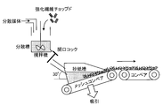
- FIG. 2 is a schematic view showing an example of a reinforcing fiber mat manufacturing apparatus according to the present invention.
- FIG. 3 is a diagram for explaining the production of a porous body according to the present invention.
- FIG. 4 is a diagram for explaining the production of the porous body according to the present invention.
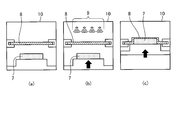
- FIG. 5 is a diagram for explaining the production of a molded product according to the present invention.
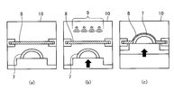
- FIG. 6 is a diagram for explaining the production of a molded product according to the present invention.
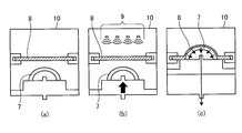
- FIG. 7 is a diagram for explaining the production of a molded product according to the present invention.
- FIG. 8 is a diagram for explaining the production of a molded product according to the present invention.
- the method for producing a molded product according to the present invention is a method for producing a molded product obtained by integrating a decorative layer on the surface of a porous body having reinforcing fibers, and a preheating step for preheating the decorative layer. And pressing the porous body against the decorative layer, or pressing the decorative layer against the porous body to shape the decorative layer, and integrating the porous body and the decorative layer together And a shaping integration step to be converted.
- the porous body preferably further contains a resin and voids in addition to the reinforcing fibers.
- the reinforcing fibers include metal fibers such as aluminum, brass and stainless steel, PAN-based, rayon-based, lignin-based, pitch-based carbon fibers, graphite fibers, insulating fibers such as glass, aramid, Examples thereof include organic fibers such as PBO, polyphenylene sulfide, polyester, acrylic, nylon, and polyethylene, and inorganic fibers such as silicon carbide and silicon nitride. Moreover, the surface treatment may be given to these fibers.
- Examples of the surface treatment include a treatment with a coupling agent, a treatment with a sizing agent, a treatment with a bundling agent, and an adhesion treatment of an additive in addition to a treatment for depositing a metal as a conductor.
- these fibers may be used individually by 1 type, and may use 2 or more types together.
- PAN-based, pitch-based, and rayon-based carbon fibers that are excellent in specific strength and specific rigidity are preferably used from the viewpoint of weight reduction effect.
- glass fibers are preferably used from the viewpoint of improving the economical efficiency of the porous body to be obtained, and it is particularly preferable to use carbon fibers and glass fibers in combination from the balance between mechanical properties and economic efficiency.
- aramid fibers are preferably used from the viewpoint of enhancing the impact absorbability and formability of the resulting porous body, and in particular, it is possible to use carbon fibers and aramid fibers in combination from the balance between mechanical properties and impact absorbability. preferable.
- a metal fiber made of a conductive metal or a reinforcing fiber coated with a metal such as nickel, copper, or ytterbium can also be used.
- reinforcing fibers selected from the group consisting of metal fibers excellent in mechanical properties such as strength and elastic modulus, pitch-based carbon fibers, and PAN-based carbon fibers can be more preferably used.
- the reinforcing fibers are discontinuous and are randomly dispersed in the porous body. More preferably, the dispersed state is substantially monofilament.
- the reinforcing fiber By making the reinforcing fiber into such an embodiment, when the precursor of the sheet-like porous body is molded by applying an external force, it becomes easy to mold into a complicated shape. Further, by setting the reinforcing fiber to such an embodiment, the void formed by the reinforcing fiber is densified, and the weak part at the fiber bundle end of the reinforcing fiber in the porous body can be minimized, so that excellent reinforcing efficiency and reliability are achieved. In addition, isotropic properties are also imparted.
- substantially monofilament means that the reinforcing fiber single yarn is present in less than 500 fineness strands. More preferably, it is dispersed as a monofilament, that is, as a single yarn.
- substantially monofilament-shaped or dispersed in a monofilament shape means that the reinforcing fiber arbitrarily selected in the porous body has a proportion of single fibers having a two-dimensional orientation angle of 1 ° or more (hereinafter referred to as a single fiber).
- fiber dispersion ratio is 80% or more, in other words, it means that two or more single fibers in contact with each other in a porous body are less than 20% in parallel. Therefore, it is particularly preferable here that the mass fraction of the fiber bundle having at least 100 filaments in the reinforcing fiber corresponds to 100%.
- the reinforcing fibers are randomly dispersed.
- that the reinforcing fibers are randomly dispersed means that the arithmetic average value of the two-dimensional orientation angle of the reinforcing fibers arbitrarily selected in the porous body is in the range of 30 ° or more and 60 ° or less.
- Such a two-dimensional orientation angle is an angle formed by a single fiber of reinforcing fibers and a single fiber that intersects with this single fiber. Of the angles formed by the intersecting single fibers, 0 ° or more, 90 It is defined as the angle on the acute angle side within the range of ° or less.
- FIGS. 1A and 1B when the single fiber 1a is used as a reference, the single fiber 1a intersects with the other single fibers 1b to 1f.
- the term “intersection” means a state in which a single fiber as a reference is observed crossing another single fiber in a two-dimensional plane to be observed, and the single fiber 1a and the single fibers 1b to 1f are not necessarily in contact with each other. There is no need to do so, and there is no exception to the state observed when they are projected. That is, when viewed with respect to the reference single fiber 1a, all of the single fibers 1b to 1f are the objects of evaluation of the two-dimensional orientation angle, and in FIG. Of the two angles to be formed, the angle is an acute angle within a range of 0 ° to 90 °.
- the method for measuring the two-dimensional orientation angle is not particularly limited, and examples thereof include a method of observing the orientation of the reinforcing fibers from the surface of the component.
- the average value of the two-dimensional orientation angle is measured by the following procedure. That is, the average value of the two-dimensional orientation angles with all the single fibers (single fibers 1b to 1f in FIG. 1) intersecting the randomly selected single fibers (single fibers 1a in FIG. 1) is measured. . For example, when there are many other single fibers that cross a certain single fiber, an arithmetic average value obtained by randomly selecting and measuring 20 other single fibers that intersect may be substituted. This measurement is repeated a total of 5 times with another single fiber as a reference, and the arithmetic average value is calculated as the arithmetic average value of the two-dimensional orientation angle.
- the fiber dispersion rate of the reinforcing fibers is preferably 90% or more, and more preferably as it approaches 100%.
- the arithmetic average value of the two-dimensional orientation angle of the reinforcing fiber is preferably in the range of 40 ° or more and 50 ° or less, and it is more preferable as it approaches 45 ° which is an ideal angle.
- any of the above upper limits may be set as the upper limit, and any of the above lower limits may be set as the lower limit.
- examples in which the reinforcing fibers do not take a discontinuous form include a sheet base material, a woven base material, and a non-crimp base material in which the reinforcing fibers are arranged in one direction.
- the reinforcing fibers are regularly and densely arranged, the voids in the porous body are reduced, making impregnation of the resin extremely difficult, forming an unimpregnated part, impregnation means and resin There are cases where the choice of species is greatly restricted.
- the form of the reinforcing fiber may be either a continuous reinforcing fiber having the same length as the porous body or a discontinuous reinforcing fiber having a finite length cut to a predetermined length. From the viewpoint of being impregnated into the resin and the amount of which can be easily adjusted, discontinuous reinforcing fibers are preferable.
- the mass average fiber length of the reinforcing fibers is in the range of 1 mm to 15 mm.
- the reinforcement efficiency of a reinforced fiber can be improved and the outstanding mechanical characteristic is given to a porous body.
- the mass average fiber length of the reinforcing fibers is 1 mm or more, the voids in the porous body can be efficiently formed, so that the density can be lowered.
- the porous body is light with the same thickness. Since a body can be obtained, it is preferable.
- the mass average fiber length of the reinforcing fiber is 15 mm or less, the reinforcing fiber is not easily bent by its own weight in the porous body, and it is preferable because it does not inhibit the expression of mechanical properties.
- the mass average fiber length is obtained by removing the resin component of the porous body by a method such as burnout or elution, and randomly selecting 400 from the remaining reinforcing fibers, measuring the length to the unit of 10 ⁇ m, and calculating the mass average of them. It can be calculated as the fiber length.
- the reinforcing fiber is in the form of a nonwoven fabric from the viewpoint of easy resin impregnation into the reinforcing fiber. Furthermore, since the reinforcing fiber has a non-woven form, in addition to the ease of handling of the non-woven fabric itself, impregnation is easy even in the case of a thermoplastic resin generally having a high viscosity. This is preferable because it is possible.
- the form of the nonwoven fabric refers to a form in which the strands and / or monofilaments of reinforcing fibers are dispersed in a plane without regularity, such as a chopped strand mat, a continuous strand mat, a papermaking mat, a carding mat, an airlaid mat, etc. (Hereinafter, these are collectively referred to as a reinforcing fiber mat).
- examples of the resin include thermoplastic resins and thermosetting resins.
- a thermosetting resin and a thermoplastic resin may be blended.
- the resin becomes a matrix resin constituting the porous body and the precursor of the porous body.
- the resin preferably contains at least one kind of thermoplastic resin.
- Thermoplastic resins include “polyethylene terephthalate (PET), polybutylene terephthalate (PBT), polytrimethylene terephthalate (PTT), polyethylene naphthalate (PEN), polyesters such as liquid crystal polyester, polyethylene (PE), polypropylene (PP) , Polyolefins such as polybutylene, polyarylene sulfides such as polyoxymethylene (POM), polyamide (PA), polyphenylene sulfide (PPS), polyketone (PK), polyetherketone (PEK), polyetheretherketone (PEEK), poly Crystalline resins such as fluorinated resins such as ether ketone ketone (PEKK), polyether nitrile (PEN), polytetrafluoroethylene, and liquid crystal polymer (LCP); , Polycarbonate (PC), polymethyl methacrylate (PMMA), polyvinyl chloride (PVC), polyvinyl
- polyolefin is preferable from the viewpoint of lightness of the obtained porous body
- polyamide is preferable from the viewpoint of strength
- amorphous resin such as polycarbonate and styrene resin is preferable from the viewpoint of surface appearance
- heat resistant Polyarylene sulfide is preferable from the viewpoint
- polyether ether ketone is preferable from the viewpoint of continuous use temperature
- fluorine resin is preferably used from the viewpoint of chemical resistance.
- the resin preferably contains at least one kind of thermosetting resin.
- Thermosetting resins include unsaturated polyesters, vinyl esters, epoxy resins, phenol resins, urea resins, melamine resins, thermosetting polyimides, copolymers thereof, modified products, and resins obtained by blending at least two of these. Can be illustrated.
- the porous body according to the present invention contains, as one of the resin components, an impact resistance improver such as an elastomer or a rubber component, and other fillers and additives as long as the object of the present invention is not impaired. May be.
- fillers and additives include inorganic fillers, flame retardants, conductivity imparting agents, crystal nucleating agents, ultraviolet absorbers, antioxidants, vibration damping agents, antibacterial agents, insect repellents, deodorants, and coloring inhibitors. , Heat stabilizers, mold release agents, antistatic agents, plasticizers, lubricants, colorants, pigments, dyes, foaming agents, antifoaming agents, or coupling agents.
- the porous body of the present invention has voids.
- the void in the present invention refers to a space formed by reinforcing fibers covered with a resin as a columnar support and overlapping or intersecting.
- voids are formed by raising the reinforcing fiber by melting or softening of the resin accompanying heating. This is based on the property that in the precursor of the porous body, the internal reinforcing fibers that have been compressed by pressurization are raised by the raising force derived from the elastic modulus.
- the voids are continuous at least in the thickness direction.
- the porous body of the present invention has a volume content (%) of reinforcing fibers of 0.5 to 55% by volume, a volume content of resin (%) of 2.5 to 85% by volume, and a volume content of voids. (%) Is preferably 10 to 97% by volume.
- the volume content of the reinforcing fiber is 0.5% by volume or more because the reinforcing effect derived from the reinforcing fiber can be made sufficient.
- the volume content of the reinforcing fibers is 55% by volume or less, the volume content of the resin with respect to the reinforcing fibers is relatively increased, and the reinforcing fibers in the porous body are bound to each other to reinforce the reinforcing fibers. Since the effect can be made sufficient, it is preferable because the mechanical properties of the porous body, particularly the bending properties can be satisfied.
- the reinforcing fibers in the porous body can be bound to each other, and the reinforcing effect of the reinforcing fibers can be made sufficient. It is preferable because it can satisfy the mechanical properties of the material, in particular the flexural modulus. On the other hand, if the volume content of the resin is 85% by volume or less, it is preferable because the formation of voids is not hindered.
- the reinforcing fiber is covered with a resin, and the thickness of the covering resin (covering thickness) is in the range of 1 ⁇ m or more and 15 ⁇ m or less.
- the covering state of the reinforcing fiber coated with the resin is at least the shape stability of the porous body and the ease of thickness control as long as the points where the single fibers of the reinforcing fibers constituting the porous body cross each other are covered.
- the resin is in a state where the resin is coated with the above-described thickness around the reinforcing fiber.
- the porous body further has shape stability and sufficient mechanical properties.
- the covering state of the reinforcing fiber coated with the resin does not need to be covered with all of the reinforcing fibers, and does not impair the shape stability, bending elastic modulus and bending strength of the porous body according to the present invention. It may be within the range.
- the void volume content is preferably in the range of 10% by volume to 97% by volume. It is preferable that the void content is 10% by volume or more because the density of the porous body becomes low and the lightness can be satisfied. On the other hand, when the void content is 97% by volume or less, in other words, the thickness of the resin coated around the reinforcing fibers becomes sufficient, so that the reinforcing fibers are reinforced in the porous body. This is preferable because it can be carried out sufficiently and the mechanical properties become high.
- the upper limit value of the volume content of the voids is preferably 97% by volume. In the present invention, the volume content is defined as 100% by volume of the total volume content of the reinforcing fibers, the resin, and the voids constituting the porous body.
- the voids are formed by a restoring force that causes the reinforcing fibers to be raised and return to the original state by lowering the viscosity of the precursor resin of the porous body.
- the reinforcing fibers are preferably bonded through a resin (thermoplastic resin or thermosetting resin), thereby exhibiting stronger compression characteristics and shape retention of the porous body.
- the density ⁇ of the porous body is preferably 0.9 g / cm 3 or less.
- the density ⁇ of the porous body is 0.9 g / cm 3 or less, it means that the mass when the porous body is made decreases, and as a result, it contributes to the weight reduction of the product. Therefore, it is preferable. More preferably, it is 0.7 g / cm ⁇ 3 > or less, More preferably, it is 0.5 g / cm ⁇ 3 > or less.
- the lower limit of the density in general, in a porous body having reinforcing fibers and a resin, the value calculated from the volume ratios of the reinforcing fibers, the resin, and the voids as the constituent components is the lower limit.
- the density of the porous body itself is 0.03 g / cm 3 or more from the viewpoint of maintaining the mechanical properties of the porous body, although it varies depending on the reinforcing fiber and resin used. Is preferred.
- the compressive strength at 50% compression measured by JIS K7220 of the porous material is preferably 1 MPa or more.
- the compressive strength is 1 MPa or more, the porous body is excellent in shape retention. Therefore, the porous body is pressed against the decorative layer, or the decorative layer is pressed against the porous body to apply the decorative layer. Can be shaped. If the compressive strength is 1 MPa or more, there is no practical problem, but it is preferably 3 MPa or more.
- the surface roughness Ra1 of the porous body is preferably 200 ⁇ m or less.
- the surface roughness Ra2 of the molded product can be set to a desired range. From the viewpoint of strengthening the adhesion between the decorative layer and the porous body, it is preferably 10 ⁇ m or more in order to facilitate the formation of mechanical anchoring, more preferably 30 ⁇ m or more, and even more preferably 50 ⁇ m or more. is there.
- the voids in the porous body are preferably continuous at least in the thickness direction.
- the porous body can have air permeability.
- a porous body has air permeability, when integrating a porous body and a decoration layer, it can decompress and integrate from the surface opposite to the surface which contact
- the adhesion of the decorative layer to the porous body can be improved.
- the decorative layer is a layer made of a film that imparts designability for the purpose of enabling the molded product to be provided as a final product.
- the film-like material include resin, metal, and wood.
- a resin film is preferable, and a resin film decorated by printing, vacuum deposition, coloring, or the like is more preferable.
- thermoplastic resin can be used as the base resin of the decoration layer.
- the thermoplastic resin is not particularly limited, but any thermoplastic resin such as polyethylene terephthalate (PET), acrylic resin (MMA), polycarbonate (PC), polyolefin (PO), acrylonitrile butadiene styrene resin (ABS), etc. Can be used.
- the resin film which forms a decoration layer can use not only a single layer but the resin film which has multiple layers, such as MMA / PC, MMA / PC / MMA, for example.
- it can select similarly to the thermoplastic resin which comprises a porous body.
- the decorative layer may have an additive depending on the purpose in addition to the above resin.
- the additive is not particularly limited as an additive, but is added for the purpose of imparting design properties such as coloring, pearly feeling and metallic feeling to the molded product.
- additives include pigments and glass beads.
- specific examples include organic pigments such as azo pigments and phthalocyanine blue, metal pigments made of metal powders such as aluminum and brass, and inorganic pigments such as chromium oxide and cobalt blue.
- metal pigments and inorganic pigments are preferred from the viewpoint of heat resistance.
- the reinforcing fiber is a dark color such as carbon fiber or aramid fiber
- a pigment having two or more layers of structures having different refractive indexes is preferably used.
- color can be developed by optical phenomena such as interference, diffraction, and scattering of light in the visible light region.
- optical phenomenon such as light interference, diffraction, or scattering
- a color can be generated by reflection of light of a specific wavelength, and therefore, it is preferably used when a dark reinforcing fiber is used.
- a hollow additive can also be used.
- hollow glass beads, porous resin particles, and the like are preferable in terms of weight reduction.
- the additive may be in the form of a sphere, fiber, or flake.
- the maximum dimension at the time of addition is preferably 200 ⁇ m or less.
- the maximum size of the additive means the maximum size of the primary particles of the additive or the maximum size of the secondary particles when the additive aggregates.
- the maximum dimension of the additive is 200 ⁇ m or less, the surface of the decorative layer becomes smooth and the design properties are improved.
- the additive was observed using an electron microscope, and an arbitrary 100 additives were randomly selected from an image enlarged so that the size could be measured to at least 1 ⁇ m unit. It is an average value of values measured by setting the length when any two points on the outer contour line of each additive are selected so that the distance is maximized as the maximum length.
- the maximum size of the additive is more preferably 150 ⁇ m or less, and further preferably 100 ⁇ m or less.
- the lower limit of the maximum dimension of the additive is preferably 1 ⁇ m or more, more preferably 5 ⁇ m or more, and more preferably 10 ⁇ m or more.
- the decorative layer preferably has a thickness of 10 ⁇ m or more and 500 ⁇ m or less.
- the thickness is less than 10 ⁇ m, it may be difficult to maintain the shape of the decorative layer when the decorative film is formed on the decorative layer in the shaping integration step.
- the thickness is thicker than 500 ⁇ m, it is possible to form a smooth surface and a surface with excellent design properties, but the mass of the molded product increases, and it is difficult to say the lightness of the molded product.
- the thickness of the decoration layer is 50 ⁇ m or more and 400 ⁇ m or less.
- the surface roughness Ra2 of the decorative layer of the molded product is preferably 100 ⁇ m or less.
- the surface roughness Ra2 is 100 ⁇ m or less, the surface becomes smooth, and more preferably 50 ⁇ m or less, and even more preferably 30 ⁇ m or less, it is possible to obtain a molded product having a more excellent design.
- the density ⁇ is preferably 1.0 g / cm 3 or less.
- the density ⁇ of the molded product is 1.0 g / cm 3 or less, it is preferable because the mass of the molded product is reduced, that is, it contributes to the weight reduction of the product. More preferably, it is 0.8 g / cm ⁇ 3 > or less, More preferably, it is 0.6 g / cm ⁇ 3 > or less.
- the density of the molded product varies depending on the reinforcing fiber and resin used, but is preferably 0.05 g / cm 3 or more from the viewpoint of maintaining the mechanical properties of the molded product.
- Examples of the method for producing the precursor include a method in which a resin in a melted or softened state is pressed or depressurized in the reinforcing fiber mat. Specifically, a method in which a laminate in which a resin is disposed from both sides and / or the center of the reinforcing fiber mat in the thickness direction is heated and pressurized to melt and impregnate the resin can be preferably exemplified from the viewpoint of ease of production.
- a method for producing a reinforcing fiber mat constituting a porous body for example, there is a method of producing a reinforcing fiber mat by dispersing reinforcing fibers in advance in the form of strands and / or substantially monofilaments.
- Reinforcing fiber mats can be manufactured using dry processes such as the airlaid method in which reinforcing fibers are dispersed into sheets by air flow, the carding method in which the reinforcing fibers are trimmed and formed into sheets while mechanically combing the reinforcing fibers.
- a wet process based on the radrite method in which paper is made by stirring in water can be cited as a known technique.
- a method of providing a fiber opening bar, a method of vibrating the fiber opening bar, a method of further finening the card eye, and adjusting the rotation speed of the card The method of doing etc. can be illustrated.
- the wet process there are a method of adjusting the stirring condition of the reinforcing fiber, a method of diluting the reinforcing fiber concentration of the dispersion, a method of adjusting the viscosity of the dispersion, a method of suppressing the vortex when the dispersion is transferred, etc. It can be illustrated.
- the reinforcing fiber mat is preferably produced by a wet process, and the ratio of reinforcing fibers in the reinforcing fiber mat is increased by increasing the concentration of input fibers or adjusting the flow rate of the dispersion and the speed of the mesh conveyor. Can be adjusted easily. For example, by slowing the speed of the mesh conveyor with respect to the flow rate of the dispersion liquid, the orientation of the fibers in the obtained reinforcing fiber mat becomes difficult to take in the take-up direction, and a bulky reinforcing fiber mat can be manufactured.
- the reinforcing fiber mat may be composed of reinforcing fibers alone, and the reinforcing fibers are mixed with a matrix resin component in the form of powder or fibers, the reinforcing fibers are mixed with an organic compound or an inorganic compound, or the reinforcing fibers They may be sealed with a resin component.
- a compression molding machine or a double belt press can be suitably used.
- the productivity can be improved by using an intermittent press system in which two or more machines for heating and cooling are arranged in parallel.
- a continuous type it is the latter, and since continuous processing can be performed easily, it is excellent in continuous productivity.
- the step of expanding the precursor to form a porous body is not particularly limited, but it is preferable to form the porous body by reducing the viscosity of the resin constituting the porous body.
- a method for reducing the viscosity of the resin it is preferable to heat the precursor.
- the heating method is not particularly limited, and examples thereof include a method of heating in contact with a mold or a hot plate set to a desired temperature, and a method of heating in a non-contact state using a heater or the like.
- thermoplastic resin When a thermoplastic resin is used as the resin constituting the porous body, it may be heated to the melting point or the softening point or higher, and when a thermosetting resin is used, it is heated at a temperature lower than the temperature at which the curing reaction starts.
- the method of controlling the thickness of the porous body is not limited as long as the precursor to be heated can be controlled to the target thickness, but the method of constraining the thickness using a metal plate or the like, the thickness by the pressure applied to the precursor
- a control method and the like are exemplified as a preferable method from the viewpoint of ease of production.
- a compression molding machine or a double belt press can be suitably used as equipment for realizing the above method.
- the productivity can be improved by using an intermittent press system in which two or more machines for heating and cooling are arranged in parallel.
- a continuous type it is the latter, and since continuous processing can be performed easily, it is excellent in continuous productivity.
- the method for forming the decorative layer on the porous body is not particularly limited.
- the decorative layer such as a resin film is placed in a mold and the porous body is inserted, such as in-mold molding or a resin film.
- Examples include out-molding such as pressing the decorative layer against the porous body or pressing the porous body against the decorative layer.
- a method particularly used in the present invention is out-molding.
- FIG. 5 is a diagram for explaining the production of a molded product using a resin film as a decorative layer according to the present invention. In the method for producing a molded product of the present invention, first, the decorative layer 8 is preheated (preheating step).
- the preheating temperature of the decoration layer 8 changes with kinds of the resin film to be used, what is necessary is just the temperature which the decoration layer 8 can shape.
- the preheating temperature of the decorative layer 8 is preferably 100 ° C. or higher.
- the porous body 7 and the decorative layer 8 can be thermally welded by heating to the melting point or softening point of the resin or higher. Improves.
- the preheating of the decoration layer 8 can be performed in a furnace whose temperature can be adjusted. In Fig.5 (a), the decoration layer 8 and the plate-shaped porous body 7 are arrange
- the distance from the IR heater 9 to the porous body 7 is set at a position farther than the decorative layer.
- a method of arranging the inside of the furnace in which the porous body 7 exists is set to a temperature lower than the temperature at which the decorative layer 8 is preheated.
- the porous body 7 is pressed against the decorative layer 8, or the decorative layer 8 is pressed against the porous layer 7 to shape the decorative layer 8, and the porous body 7 and the decorative layer 8 are bonded together.
- the method of pressing the decorative layer 8 against the porous body 7 is not particularly limited.
- a method of pressing the decorative layer 8 by physically moving it or a furnace that is a closed space 10 a pressure difference may be generated between the space including the porous body 7 and the space not including the porous body 7 partitioned with the decorative layer 8 as a boundary.
- the pressure difference is generated and pressed, as shown in FIG.
- a method of pressing the space between the porous body 7 and the decorative layer 8 in a vacuum state, the decorative layer 8 For example, there is a method in which compressed air is sent into a space opposite to the porous body 7 and the decorative layer 8 is pressed against the porous body 7. At this time, a vacuum state and a pressurized state may be combined, and a solvent such as water or oil may be used instead of compressed air. In this way, by shaping the decorative layer 8 into the porous body 7 by creating a pressure difference in each space with the decorative layer 8 as a boundary in the closed space, the shapeability to a more complicated shape is achieved. Can be improved, which is preferable.
- the decorative layer 8 can easily enter the porous body 7, and the integration of the porous body 7 and the decorative layer 8 is also strong. Therefore, it is preferable. It is more preferable to perform either or both of shaping and integration by generating a pressure difference in both spaces with the decoration layer 8 as a boundary, and pressure difference between both spaces with the decoration layer 8 as a boundary. It is more preferable that the porous body and the decorative layer are integrated with each other by shaping. Even when the integration is performed by the pressure difference between the two spaces, the integration may be further strengthened by a method described later.
- the porous body 7 is pressed against the decorative layer 8 to shape the decorative layer 8 into a hemispherical shape, but the decorative layer 8 is pressed against the porous body 7 to decorate.
- the layer 8 may be shaped into a hemisphere.
- the pressing force in the shaping integration step may be appropriately selected depending on the preheating temperature of the decorative layer 8 and the porous body 7, but is preferably 1 KN or less.
- the lower limit of the pressing force is not particularly limited, but is preferably 1N or more and more preferably 10N or more from the viewpoint of shaping the decorative layer 8.
- the surface area which anchoring or the porous body 7 and the decoration layer 8 contacts increases, and adhesiveness improves.
- the depth at which the decorative layer 8 penetrates into the porous body 7 is not particularly limited, but the length in the thickness direction of the porous body is preferably 30 ⁇ m or more, more preferably 50 ⁇ m or more, and further 100 ⁇ m or more. preferable.
- the shaping integration step it is preferable to shape the decorative layer 8 while reducing the pressure inside the furnace 10 and integrate it with the porous body 7. If the reinforcing fibers of the porous body 7 enter the decorative layer 8 by forming and integrating under reduced pressure, the adhesion between the porous body 7 and the decorative layer 8 is improved by the anchoring effect. At this time, there is no particular limitation on the length of the reinforcing fibers that have entered the decorative layer 8, but it is preferably 10 ⁇ m or more, more preferably 30 ⁇ m or more, and even more preferably 50 ⁇ m or more.
- the state of the reinforcing fiber that enters the decorative layer 8 is not particularly limited, but 10% or more of the total length of the reinforcing fiber is preferably infiltrated, and more preferably 20% or more is infiltrated.
- the method of depressurization is not particularly limited, but includes a method of depressurizing by operating a vacuum pump or the like, a method of depressurizing a space adjacent to the closed space and opening the connection with the closed space, etc. Can be illustrated. From the viewpoint of stable pressure reduction, the latter method is preferable.
- These pressure reductions can be appropriately set according to the shape of the porous body and the type and thickness of the resin used for the decorative layer. By reducing the pressure from the porous body 7 side, the adhesion between the porous body 7 and the decorative layer 8 can be further improved.
- the integration method is not particularly limited, and examples thereof include a method using an adhesive and a heat welding method.
- the thermal welding method is preferable, and examples thereof include a vibration welding method, an ultrasonic welding method, a laser welding method, and a hot plate welding method. From the viewpoint of adhesiveness and process simplicity, ultrasonic welding and hot plate welding are preferably used.
- the molded article of the present invention produced as described above includes, for example, “a personal computer, a display, an OA device, a mobile phone, a portable information terminal, a PDA (a portable information terminal such as an electronic notebook), a video camera, an optical device, an audio, Cases such as air conditioners, lighting equipment, entertainment equipment, toy goods, and other home appliances, trays, chassis, interior members, diaphragms, speaker cones, or cases thereof, etc., electrical and electronic equipment parts, such as “speaker cones” Acoustic members, "Various members, Various frames, Various hinges, Various arms, Various axles, Various wheel bearings, Various beams", “Hood, Roof, Door, Fender, Trunk lid, Side panel, Rear end panel, Front body, Under Body, various pillars, various members, various frames, various beams, various supports, various rails, various Outer parts such as “hinge” or body parts, “bumper, bumper beam, molding, under cover, engine cover, current plate
- Vf (volume%) (Wf / ⁇ f) / ⁇ Wf / ⁇ f + (Ws ⁇ Wf) / ⁇ r ⁇ ⁇ 100 ⁇ f: density of reinforcing fiber (g / cm 3 ) ⁇ r: Resin density (g / cm 3 )
- Density of molded product ⁇ m A portion including the porous body and the decorative layer was cut out from the molded product as a test piece, and (2) the apparent density of the molded product was measured in the same manner as the density ⁇ of the porous material, and the density ⁇ m was calculated.
- volume content of voids in the porous body A test piece was cut out from the porous body 10 mm in length and 10 mm in width, and the cross section was scanned with a scanning electron microscope (SEM) (S-4800, manufactured by Hitachi High-Technologies Corporation). Observed and photographed 10 locations at equal intervals from the surface of the sample piece at a magnification of 1000 times. For each image, the area Aa of the void in the image was determined. Further, the void ratio was calculated by dividing the void area Aa by the area of the entire image. The volume content of voids in the porous body was determined by arithmetic average from the void ratios at a total of 50 locations, which were taken at 10 locations each with 5 test pieces.
- SEM scanning electron microscope
- the reinforcing fiber mat was manufactured using the reinforcing fiber mat manufacturing apparatus shown in FIG. The manufacturing apparatus shown in FIG.
- the papermaking tank includes a mesh conveyor having a papermaking surface having a width of 500 mm at the bottom, and a conveyor capable of transporting a carbon fiber substrate (papermaking substrate) is connected to the mesh conveyor. Papermaking was performed at a carbon fiber concentration of 0.05% by mass in the dispersion.
- the paper-made carbon fiber substrate was dried in a drying furnace at 200 ° C. for 30 minutes to obtain a reinforcing fiber mat having a basis weight of 100 g / m 2 .
- PP resin 100 g of basis weight comprising 80% by mass of unmodified polypropylene resin (“Prime Polypro” (registered trademark) J105G manufactured by Prime Polymer Co., Ltd.) and 20% by mass of acid-modified polypropylene resin (“Admer” QB510 manufactured by Mitsui Chemicals, Inc.) A resin sheet of / m 2 was produced.
- a PET resin film “PICASUS” manufactured by Toray Industries, Inc. was prepared as a decorative layer 8B.
- a shrink film made of polyvinyl chloride resin was prepared as a decorative layer 8C.
- a foamed polypropylene sheet “F-cell” CP3030 manufactured by Furukawa Electric Co., Ltd. was prepared as a foam.
- Porous body 7A The following steps (I) to (V) are performed using a porous body precursor and a press molding die having a press machine hot plate 3 and a die 4 shown in FIG. 3 and capable of producing a flat plate. As a result, a porous body 7A was obtained.
- Porous body 7B A semispherical porous body 7B was obtained in the same manner as the porous body 7A, except that the mold 4 capable of producing a hemispherical shape as shown in FIG. 4 was used.
- Example 1 A porous body 7A was prepared as the porous body 7, and a decorative layer 8A was prepared as the decorative layer 8. As shown in FIG. 5, the porous body 7 was placed in a furnace 10 at a temperature of 80 ° C., and the decorative layer 8 was preheated to 130 ° C. by the IR heater 9 (preheating step). After heating the decorative layer 8, the porous body 7 is pressed against the decorative layer 8 at 0.03 KN to shape the decorative layer 8, and the porous body 7 and the decorative layer 8 are integrated ( Shaped integration step), a molded product was obtained. Table 1 shows the characteristics of the molded product obtained in Example 1.
- Example 2 A molded product was obtained as shown in FIG. 6 in the same manner as in Example 1 except that the porous body 7B was used as the porous body 7.
- the properties of the molded product obtained in Example 2 are shown in Table 1.
- Example 3 A porous body 7B was used as the porous body 7, and a decorative layer 8C was used as the decorative layer 8.
- the decorative layer 8 was placed on the porous body 7, and warm air of 150 ° C. was blown with a dryer, and the decorative layer 8 was adhered to the porous body 7. Then, the porous body 7 and the decoration layer 8 were integrated using the ultrasonic welding machine, and the molded article was obtained.
- the properties of the molded product obtained in Example 3 are shown in Table 1.
- Example 4 A molded product was obtained in the same manner as in Example 2 except that the decorative layer 8B was used as the decorative layer 8 and the preheating temperature condition was 160 ° C.
- the properties of the molded product obtained in Example 4 are shown in Table 1.
- Example 5 Using the porous body 7A as the porous body 7 and the decorative layer 8A as the decorative layer 8, the space between the porous body 7 and the decorative layer 8 in the furnace 10 is in a vacuum state as shown in FIG. As in Example 1, except that the porous body 7 is pressed against the decorative layer 8 at 0.1 KN, the decorative layer 8 is shaped and the porous body 7 and the decorative layer 8 are integrated. (Molding integration process) to obtain a molded product. The properties of the molded product obtained in Example 5 are shown in Table 1.
- Example 6 A molded product was obtained in the same manner as in Example 5 except that the preheating temperature was 150 ° C.
- the properties of the molded product obtained in Example 6 are shown in Table 1.
- Example 7 Except for using the porous body 7B as the porous body 7, using the decorative layer 8A as the decorative layer 8, and pressing the porous body 7 against the decorative layer 8 at 0.1 KN as shown in FIG.
- the decorative layer 8 is shaped, and the pressure is reduced from the porous body 7 side (the side opposite to the side in contact with the decorative layer 8), so that the porous body 7 and the decorative layer 8 are formed.
- the properties of the molded product obtained in Example 7 are shown in Table 1.
- Comparative Example 1 A molded product was obtained in the same manner as in Example 5 except that a foamed body (independent) composed only of a resin not containing reinforcing fibers was used as the porous body. Table 1 shows the characteristics of the molded product obtained in Comparative Example 1.
- Comparative Example 2 A molded product was obtained in the same manner as in Comparative Example 1 except that a mold for supporting a porous body made of foam (independent) was used. Table 1 shows the characteristics of the molded product obtained in Comparative Example 1.
- Comparative Example 3 A molded product was obtained in the same manner as in Example 2 except that the preheating step for preheating the decorative layer 8 was omitted. Table 1 shows the characteristics of the molded product obtained in Comparative Example 3.
- Comparative Example 4 After the preheating step, a molded product was obtained in the same manner as in Example 2 except that the decorative layer 8 was not pressed against the porous body 7 and placed on the porous body 7 without shaping. . The properties of the molded product obtained in Comparative Example 4 are shown in Table 1.
- the porous body and the decorative layer were integrated together with the shaping of the decorative layer, and thus the productivity was excellent. Moreover, since the porous body which has high compressive strength including another aspect is used, the molded article was able to be obtained without using a type
- Example 6 By increasing the pressing force, reinforcing fibers are added to the decorative layer. Infiltrated and improved adhesion. Moreover, about Example 6, it was also possible to improve the heat-weldability between resin by changing preheating conditions, and to improve adhesiveness.
- Example 7 the decorative layer and the porous body were more firmly integrated by making the decorative layer side of the porous body into a reduced pressure state by reducing the pressure through the porous body. On the other hand, in Comparative Example 1, the porous body was crushed by a high pressing force, and a molded product could not be obtained.
- Comparative Example 2 a mold for shaping and molding was used to prevent the porous body from collapsing, but the porous body was crushed (thinned) in the thickness direction and integrated, but it was necessary. The shape of the molded product could not be obtained.
- Comparative Examples 3 and 4 the adhesion between the porous body and the decorative layer is low, and the decorative layer cannot shape the shape along the porous body, and a necessary molded product can be obtained. There wasn't. From these, it is obvious that the manufacturing method of the molded product of the present application is excellent not only in that the decorative layer can be easily shaped and integrated into the porous body, but also in that the degree of freedom of molding conditions is high. is there.
Abstract
L'invention concerne un procédé de fabrication d'un article moulé qui est léger et présente une excellente rigidité, une conception améliorée et une excellente aptitude à la fabrication. La présente invention concerne un procédé de fabrication d'un article moulé obtenu par intégration d'une couche décorative sur la surface d'un corps poreux, le procédé étant caractérisé en ce qu'il comprend : une étape de préchauffage consistant à préchauffer la couche décorative ; et une étape d'intégration de mise en forme consistant à placer le corps poreux contre la couche décorative ou la couche décorative contre le corps poreux pour mettre en forme la couche décorative tout en intégrant le corps poreux et la couche décorative.
Priority Applications (5)
| Application Number | Priority Date | Filing Date | Title |
|---|---|---|---|
| CN201980021904.3A CN111936301B (zh) | 2018-03-30 | 2019-03-28 | 成型品的制造方法 |
| US16/976,838 US20210001536A1 (en) | 2018-03-30 | 2019-03-28 | Method for manufacturing molded article |
| JP2019517998A JP7294131B2 (ja) | 2018-03-30 | 2019-03-28 | 成形品の製造方法 |
| KR1020207026698A KR20200132876A (ko) | 2018-03-30 | 2019-03-28 | 성형품의 제조 방법 |
| EP19775044.1A EP3778195B1 (fr) | 2018-03-30 | 2019-03-28 | Procédé de fabrication d'un article moulé |
Applications Claiming Priority (2)
| Application Number | Priority Date | Filing Date | Title |
|---|---|---|---|
| JP2018069182 | 2018-03-30 | ||
| JP2018-069182 | 2018-03-30 |
Publications (1)
| Publication Number | Publication Date |
|---|---|
| WO2019189582A1 true WO2019189582A1 (fr) | 2019-10-03 |
Family
ID=68060293
Family Applications (1)
| Application Number | Title | Priority Date | Filing Date |
|---|---|---|---|
| PCT/JP2019/013619 WO2019189582A1 (fr) | 2018-03-30 | 2019-03-28 | Procédé de fabrication d'un article moulé |
Country Status (7)
| Country | Link |
|---|---|
| US (1) | US20210001536A1 (fr) |
| EP (1) | EP3778195B1 (fr) |
| JP (1) | JP7294131B2 (fr) |
| KR (1) | KR20200132876A (fr) |
| CN (1) | CN111936301B (fr) |
| TW (1) | TW201945157A (fr) |
| WO (1) | WO2019189582A1 (fr) |
Cited By (1)
| Publication number | Priority date | Publication date | Assignee | Title |
|---|---|---|---|---|
| CN111730850A (zh) * | 2020-06-18 | 2020-10-02 | 江苏汤臣新材料科技有限公司 | 一种有机玻璃半球形结构均匀压制模具及其压制方法 |
Families Citing this family (2)
| Publication number | Priority date | Publication date | Assignee | Title |
|---|---|---|---|---|
| CN110662639B (zh) * | 2017-03-21 | 2022-06-10 | 麦格纳外饰公司 | 两铰链的一体成型组件 |
| DE102021006465A1 (de) | 2021-12-29 | 2023-06-29 | Demmel Aktiengesellschaft | Hinterleuchtetes Fahrzeug-Zierteil, insbesondere Fahrzeug-Emblem |
Citations (6)
| Publication number | Priority date | Publication date | Assignee | Title |
|---|---|---|---|---|
| JPS6123965B2 (fr) | 1980-09-30 | 1986-06-09 | Nippon Kuraisu Kk | |
| JPH09254248A (ja) | 1996-03-21 | 1997-09-30 | Sumitomo Chem Co Ltd | 繊維強化熱可塑性樹脂中空成形体およびその製造方法 |
| JP2001150587A (ja) * | 1999-11-30 | 2001-06-05 | Sumitomo Chem Co Ltd | 積層パネル |
| WO2015029634A1 (fr) | 2013-08-30 | 2015-03-05 | 東レ株式会社 | Structure en sandwich et article moulé intégré la mettant en oeuvre, ainsi que des procédés de production associés |
| JP2016078451A (ja) | 2014-10-17 | 2016-05-16 | 東レ株式会社 | 繊維強化複合材料の製造方法、樹脂基材およびプリフォーム |
| JP2018047681A (ja) * | 2016-09-16 | 2018-03-29 | 山本印刷株式会社 | 加飾樹脂シートを備えた成形品とその製造方法 |
Family Cites Families (7)
| Publication number | Priority date | Publication date | Assignee | Title |
|---|---|---|---|---|
| DE69525041T2 (de) * | 1994-03-04 | 2002-10-02 | Armacel Pty Ltd | Verfahren und vorrichtung zum herstellen von strukturierten gegenständen |
| JPH08238705A (ja) * | 1995-03-07 | 1996-09-17 | Sumitomo Chem Co Ltd | 衝撃吸収部品 |
| US7837911B2 (en) * | 2004-01-26 | 2010-11-23 | Sabic Innovative Plastics Ip B.V. | Methods of forming a layered article |
| CN1914024B (zh) * | 2004-01-26 | 2011-06-29 | 沙伯基础创新塑料知识产权有限公司 | 结构增强的树脂制品及其制备方法 |
| DE102011000336B9 (de) * | 2011-01-26 | 2012-11-29 | Novem Car Interior Design Gmbh | Verfahren zur Herstellung eines Formteils mittels Tiefziehen |
| EP2732952B1 (fr) * | 2011-07-12 | 2017-03-01 | Riken Technos Corporation | Article moulé revêtu d'un film |
| JP6462547B2 (ja) * | 2015-10-02 | 2019-01-30 | 天昇電気工業株式会社 | 樹脂成形品および樹脂成形品の製造方法 |
-
2019
- 2019-03-28 US US16/976,838 patent/US20210001536A1/en not_active Abandoned
- 2019-03-28 EP EP19775044.1A patent/EP3778195B1/fr active Active
- 2019-03-28 KR KR1020207026698A patent/KR20200132876A/ko unknown
- 2019-03-28 CN CN201980021904.3A patent/CN111936301B/zh active Active
- 2019-03-28 WO PCT/JP2019/013619 patent/WO2019189582A1/fr active Application Filing
- 2019-03-28 JP JP2019517998A patent/JP7294131B2/ja active Active
- 2019-03-29 TW TW108111147A patent/TW201945157A/zh unknown
Patent Citations (6)
| Publication number | Priority date | Publication date | Assignee | Title |
|---|---|---|---|---|
| JPS6123965B2 (fr) | 1980-09-30 | 1986-06-09 | Nippon Kuraisu Kk | |
| JPH09254248A (ja) | 1996-03-21 | 1997-09-30 | Sumitomo Chem Co Ltd | 繊維強化熱可塑性樹脂中空成形体およびその製造方法 |
| JP2001150587A (ja) * | 1999-11-30 | 2001-06-05 | Sumitomo Chem Co Ltd | 積層パネル |
| WO2015029634A1 (fr) | 2013-08-30 | 2015-03-05 | 東レ株式会社 | Structure en sandwich et article moulé intégré la mettant en oeuvre, ainsi que des procédés de production associés |
| JP2016078451A (ja) | 2014-10-17 | 2016-05-16 | 東レ株式会社 | 繊維強化複合材料の製造方法、樹脂基材およびプリフォーム |
| JP2018047681A (ja) * | 2016-09-16 | 2018-03-29 | 山本印刷株式会社 | 加飾樹脂シートを備えた成形品とその製造方法 |
Non-Patent Citations (1)
| Title |
|---|
| See also references of EP3778195A4 |
Cited By (1)
| Publication number | Priority date | Publication date | Assignee | Title |
|---|---|---|---|---|
| CN111730850A (zh) * | 2020-06-18 | 2020-10-02 | 江苏汤臣新材料科技有限公司 | 一种有机玻璃半球形结构均匀压制模具及其压制方法 |
Also Published As
| Publication number | Publication date |
|---|---|
| EP3778195A1 (fr) | 2021-02-17 |
| EP3778195B1 (fr) | 2023-07-12 |
| JP7294131B2 (ja) | 2023-06-20 |
| KR20200132876A (ko) | 2020-11-25 |
| EP3778195A4 (fr) | 2021-12-01 |
| US20210001536A1 (en) | 2021-01-07 |
| TW201945157A (zh) | 2019-12-01 |
| CN111936301B (zh) | 2023-04-04 |
| CN111936301A (zh) | 2020-11-13 |
| JPWO2019189582A1 (ja) | 2021-02-12 |
Similar Documents
| Publication | Publication Date | Title |
|---|---|---|
| TWI609900B (zh) | 纖維強化樹脂片、一體化成形品及其等之製造方法 | |
| KR102117241B1 (ko) | 구조체의 제조 방법 | |
| JP6822147B2 (ja) | 構造体 | |
| TW201444678A (zh) | 夾芯積層體、夾芯構造體及使用其之一體化成形品及彼等之製造方法 | |
| WO2019189582A1 (fr) | Procédé de fabrication d'un article moulé | |
| TWI798405B (zh) | 成形品之製造方法 | |
| JP7143588B2 (ja) | 構造体及びその製造方法 | |
| EP3778210B1 (fr) | Procédé de fabrication d'article moulé et préforme d'article moulé | |
| TWI820105B (zh) | 成形品及成形品之製造方法 | |
| JP2018104482A (ja) | 構造体 |
Legal Events
| Date | Code | Title | Description |
|---|---|---|---|
| ENP | Entry into the national phase |
Ref document number: 2019517998 Country of ref document: JP Kind code of ref document: A |
|
| 121 | Ep: the epo has been informed by wipo that ep was designated in this application |
Ref document number: 19775044 Country of ref document: EP Kind code of ref document: A1 |
|
| WWE | Wipo information: entry into national phase |
Ref document number: 2019775044 Country of ref document: EP |