WO2019189582A1 - 成形品の製造方法 - Google Patents
成形品の製造方法 Download PDFInfo
- Publication number
- WO2019189582A1 WO2019189582A1 PCT/JP2019/013619 JP2019013619W WO2019189582A1 WO 2019189582 A1 WO2019189582 A1 WO 2019189582A1 JP 2019013619 W JP2019013619 W JP 2019013619W WO 2019189582 A1 WO2019189582 A1 WO 2019189582A1
- Authority
- WO
- WIPO (PCT)
- Prior art keywords
- porous body
- decorative layer
- molded product
- producing
- resin
- Prior art date
Links
Images


Classifications
-
- B—PERFORMING OPERATIONS; TRANSPORTING
- B29—WORKING OF PLASTICS; WORKING OF SUBSTANCES IN A PLASTIC STATE IN GENERAL
- B29C—SHAPING OR JOINING OF PLASTICS; SHAPING OF MATERIAL IN A PLASTIC STATE, NOT OTHERWISE PROVIDED FOR; AFTER-TREATMENT OF THE SHAPED PRODUCTS, e.g. REPAIRING
- B29C51/00—Shaping by thermoforming, i.e. shaping sheets or sheet like preforms after heating, e.g. shaping sheets in matched moulds or by deep-drawing; Apparatus therefor
- B29C51/02—Combined thermoforming and manufacture of the preform
-
- B—PERFORMING OPERATIONS; TRANSPORTING
- B29—WORKING OF PLASTICS; WORKING OF SUBSTANCES IN A PLASTIC STATE IN GENERAL
- B29B—PREPARATION OR PRETREATMENT OF THE MATERIAL TO BE SHAPED; MAKING GRANULES OR PREFORMS; RECOVERY OF PLASTICS OR OTHER CONSTITUENTS OF WASTE MATERIAL CONTAINING PLASTICS
- B29B15/00—Pretreatment of the material to be shaped, not covered by groups B29B7/00 - B29B13/00
- B29B15/08—Pretreatment of the material to be shaped, not covered by groups B29B7/00 - B29B13/00 of reinforcements or fillers
- B29B15/10—Coating or impregnating independently of the moulding or shaping step
- B29B15/12—Coating or impregnating independently of the moulding or shaping step of reinforcements of indefinite length
- B29B15/14—Coating or impregnating independently of the moulding or shaping step of reinforcements of indefinite length of filaments or wires
-
- B—PERFORMING OPERATIONS; TRANSPORTING
- B29—WORKING OF PLASTICS; WORKING OF SUBSTANCES IN A PLASTIC STATE IN GENERAL
- B29C—SHAPING OR JOINING OF PLASTICS; SHAPING OF MATERIAL IN A PLASTIC STATE, NOT OTHERWISE PROVIDED FOR; AFTER-TREATMENT OF THE SHAPED PRODUCTS, e.g. REPAIRING
- B29C43/00—Compression moulding, i.e. applying external pressure to flow the moulding material; Apparatus therefor
- B29C43/02—Compression moulding, i.e. applying external pressure to flow the moulding material; Apparatus therefor of articles of definite length, i.e. discrete articles
- B29C43/18—Compression moulding, i.e. applying external pressure to flow the moulding material; Apparatus therefor of articles of definite length, i.e. discrete articles incorporating preformed parts or layers, e.g. compression moulding around inserts or for coating articles
- B29C43/183—Compression moulding, i.e. applying external pressure to flow the moulding material; Apparatus therefor of articles of definite length, i.e. discrete articles incorporating preformed parts or layers, e.g. compression moulding around inserts or for coating articles the preformed layer being a lining, e.g. shaped in the mould before compression moulding, or a preformed shell adapted to the shape of the mould
-
- B—PERFORMING OPERATIONS; TRANSPORTING
- B29—WORKING OF PLASTICS; WORKING OF SUBSTANCES IN A PLASTIC STATE IN GENERAL
- B29C—SHAPING OR JOINING OF PLASTICS; SHAPING OF MATERIAL IN A PLASTIC STATE, NOT OTHERWISE PROVIDED FOR; AFTER-TREATMENT OF THE SHAPED PRODUCTS, e.g. REPAIRING
- B29C51/00—Shaping by thermoforming, i.e. shaping sheets or sheet like preforms after heating, e.g. shaping sheets in matched moulds or by deep-drawing; Apparatus therefor
- B29C51/18—Thermoforming apparatus
- B29C51/20—Thermoforming apparatus having movable moulds or mould parts
-
- B—PERFORMING OPERATIONS; TRANSPORTING
- B29—WORKING OF PLASTICS; WORKING OF SUBSTANCES IN A PLASTIC STATE IN GENERAL
- B29C—SHAPING OR JOINING OF PLASTICS; SHAPING OF MATERIAL IN A PLASTIC STATE, NOT OTHERWISE PROVIDED FOR; AFTER-TREATMENT OF THE SHAPED PRODUCTS, e.g. REPAIRING
- B29C51/00—Shaping by thermoforming, i.e. shaping sheets or sheet like preforms after heating, e.g. shaping sheets in matched moulds or by deep-drawing; Apparatus therefor
- B29C51/26—Component parts, details or accessories; Auxiliary operations
- B29C51/42—Heating or cooling
- B29C51/421—Heating or cooling of preforms, specially adapted for thermoforming
- B29C51/425—Heating or cooling of preforms, specially adapted for thermoforming using movable heating devices
-
- B—PERFORMING OPERATIONS; TRANSPORTING
- B29—WORKING OF PLASTICS; WORKING OF SUBSTANCES IN A PLASTIC STATE IN GENERAL
- B29C—SHAPING OR JOINING OF PLASTICS; SHAPING OF MATERIAL IN A PLASTIC STATE, NOT OTHERWISE PROVIDED FOR; AFTER-TREATMENT OF THE SHAPED PRODUCTS, e.g. REPAIRING
- B29C65/00—Joining or sealing of preformed parts, e.g. welding of plastics materials; Apparatus therefor
- B29C65/02—Joining or sealing of preformed parts, e.g. welding of plastics materials; Apparatus therefor by heating, with or without pressure
-
- B—PERFORMING OPERATIONS; TRANSPORTING
- B29—WORKING OF PLASTICS; WORKING OF SUBSTANCES IN A PLASTIC STATE IN GENERAL
- B29C—SHAPING OR JOINING OF PLASTICS; SHAPING OF MATERIAL IN A PLASTIC STATE, NOT OTHERWISE PROVIDED FOR; AFTER-TREATMENT OF THE SHAPED PRODUCTS, e.g. REPAIRING
- B29C67/00—Shaping techniques not covered by groups B29C39/00 - B29C65/00, B29C70/00 or B29C73/00
- B29C67/20—Shaping techniques not covered by groups B29C39/00 - B29C65/00, B29C70/00 or B29C73/00 for porous or cellular articles, e.g. of foam plastics, coarse-pored
-
- B—PERFORMING OPERATIONS; TRANSPORTING
- B29—WORKING OF PLASTICS; WORKING OF SUBSTANCES IN A PLASTIC STATE IN GENERAL
- B29C—SHAPING OR JOINING OF PLASTICS; SHAPING OF MATERIAL IN A PLASTIC STATE, NOT OTHERWISE PROVIDED FOR; AFTER-TREATMENT OF THE SHAPED PRODUCTS, e.g. REPAIRING
- B29C70/00—Shaping composites, i.e. plastics material comprising reinforcements, fillers or preformed parts, e.g. inserts
- B29C70/04—Shaping composites, i.e. plastics material comprising reinforcements, fillers or preformed parts, e.g. inserts comprising reinforcements only, e.g. self-reinforcing plastics
- B29C70/06—Fibrous reinforcements only
-
- B—PERFORMING OPERATIONS; TRANSPORTING
- B29—WORKING OF PLASTICS; WORKING OF SUBSTANCES IN A PLASTIC STATE IN GENERAL
- B29B—PREPARATION OR PRETREATMENT OF THE MATERIAL TO BE SHAPED; MAKING GRANULES OR PREFORMS; RECOVERY OF PLASTICS OR OTHER CONSTITUENTS OF WASTE MATERIAL CONTAINING PLASTICS
- B29B13/00—Conditioning or physical treatment of the material to be shaped
- B29B13/02—Conditioning or physical treatment of the material to be shaped by heating
- B29B13/023—Half-products, e.g. films, plates
-
- B—PERFORMING OPERATIONS; TRANSPORTING
- B29—WORKING OF PLASTICS; WORKING OF SUBSTANCES IN A PLASTIC STATE IN GENERAL
- B29C—SHAPING OR JOINING OF PLASTICS; SHAPING OF MATERIAL IN A PLASTIC STATE, NOT OTHERWISE PROVIDED FOR; AFTER-TREATMENT OF THE SHAPED PRODUCTS, e.g. REPAIRING
- B29C43/00—Compression moulding, i.e. applying external pressure to flow the moulding material; Apparatus therefor
- B29C43/02—Compression moulding, i.e. applying external pressure to flow the moulding material; Apparatus therefor of articles of definite length, i.e. discrete articles
- B29C43/18—Compression moulding, i.e. applying external pressure to flow the moulding material; Apparatus therefor of articles of definite length, i.e. discrete articles incorporating preformed parts or layers, e.g. compression moulding around inserts or for coating articles
- B29C43/183—Compression moulding, i.e. applying external pressure to flow the moulding material; Apparatus therefor of articles of definite length, i.e. discrete articles incorporating preformed parts or layers, e.g. compression moulding around inserts or for coating articles the preformed layer being a lining, e.g. shaped in the mould before compression moulding, or a preformed shell adapted to the shape of the mould
- B29C43/184—Compression moulding, i.e. applying external pressure to flow the moulding material; Apparatus therefor of articles of definite length, i.e. discrete articles incorporating preformed parts or layers, e.g. compression moulding around inserts or for coating articles the preformed layer being a lining, e.g. shaped in the mould before compression moulding, or a preformed shell adapted to the shape of the mould shaped by the compression of the material during moulding
-
- B—PERFORMING OPERATIONS; TRANSPORTING
- B29—WORKING OF PLASTICS; WORKING OF SUBSTANCES IN A PLASTIC STATE IN GENERAL
- B29C—SHAPING OR JOINING OF PLASTICS; SHAPING OF MATERIAL IN A PLASTIC STATE, NOT OTHERWISE PROVIDED FOR; AFTER-TREATMENT OF THE SHAPED PRODUCTS, e.g. REPAIRING
- B29C51/00—Shaping by thermoforming, i.e. shaping sheets or sheet like preforms after heating, e.g. shaping sheets in matched moulds or by deep-drawing; Apparatus therefor
- B29C51/002—Shaping by thermoforming, i.e. shaping sheets or sheet like preforms after heating, e.g. shaping sheets in matched moulds or by deep-drawing; Apparatus therefor characterised by the choice of material
-
- B—PERFORMING OPERATIONS; TRANSPORTING
- B29—WORKING OF PLASTICS; WORKING OF SUBSTANCES IN A PLASTIC STATE IN GENERAL
- B29C—SHAPING OR JOINING OF PLASTICS; SHAPING OF MATERIAL IN A PLASTIC STATE, NOT OTHERWISE PROVIDED FOR; AFTER-TREATMENT OF THE SHAPED PRODUCTS, e.g. REPAIRING
- B29C51/00—Shaping by thermoforming, i.e. shaping sheets or sheet like preforms after heating, e.g. shaping sheets in matched moulds or by deep-drawing; Apparatus therefor
- B29C51/08—Deep drawing or matched-mould forming, i.e. using mechanical means only
-
- B—PERFORMING OPERATIONS; TRANSPORTING
- B29—WORKING OF PLASTICS; WORKING OF SUBSTANCES IN A PLASTIC STATE IN GENERAL
- B29C—SHAPING OR JOINING OF PLASTICS; SHAPING OF MATERIAL IN A PLASTIC STATE, NOT OTHERWISE PROVIDED FOR; AFTER-TREATMENT OF THE SHAPED PRODUCTS, e.g. REPAIRING
- B29C51/00—Shaping by thermoforming, i.e. shaping sheets or sheet like preforms after heating, e.g. shaping sheets in matched moulds or by deep-drawing; Apparatus therefor
- B29C51/10—Forming by pressure difference, e.g. vacuum
-
- B—PERFORMING OPERATIONS; TRANSPORTING
- B29—WORKING OF PLASTICS; WORKING OF SUBSTANCES IN A PLASTIC STATE IN GENERAL
- B29C—SHAPING OR JOINING OF PLASTICS; SHAPING OF MATERIAL IN A PLASTIC STATE, NOT OTHERWISE PROVIDED FOR; AFTER-TREATMENT OF THE SHAPED PRODUCTS, e.g. REPAIRING
- B29C51/00—Shaping by thermoforming, i.e. shaping sheets or sheet like preforms after heating, e.g. shaping sheets in matched moulds or by deep-drawing; Apparatus therefor
- B29C51/12—Shaping by thermoforming, i.e. shaping sheets or sheet like preforms after heating, e.g. shaping sheets in matched moulds or by deep-drawing; Apparatus therefor of articles having inserts or reinforcements
-
- B—PERFORMING OPERATIONS; TRANSPORTING
- B29—WORKING OF PLASTICS; WORKING OF SUBSTANCES IN A PLASTIC STATE IN GENERAL
- B29C—SHAPING OR JOINING OF PLASTICS; SHAPING OF MATERIAL IN A PLASTIC STATE, NOT OTHERWISE PROVIDED FOR; AFTER-TREATMENT OF THE SHAPED PRODUCTS, e.g. REPAIRING
- B29C51/00—Shaping by thermoforming, i.e. shaping sheets or sheet like preforms after heating, e.g. shaping sheets in matched moulds or by deep-drawing; Apparatus therefor
- B29C51/16—Lining or labelling
-
- B—PERFORMING OPERATIONS; TRANSPORTING
- B29—WORKING OF PLASTICS; WORKING OF SUBSTANCES IN A PLASTIC STATE IN GENERAL
- B29K—INDEXING SCHEME ASSOCIATED WITH SUBCLASSES B29B, B29C OR B29D, RELATING TO MOULDING MATERIALS OR TO MATERIALS FOR MOULDS, REINFORCEMENTS, FILLERS OR PREFORMED PARTS, e.g. INSERTS
- B29K2105/00—Condition, form or state of moulded material or of the material to be shaped
- B29K2105/06—Condition, form or state of moulded material or of the material to be shaped containing reinforcements, fillers or inserts
- B29K2105/12—Condition, form or state of moulded material or of the material to be shaped containing reinforcements, fillers or inserts of short lengths, e.g. chopped filaments, staple fibres or bristles
-
- B—PERFORMING OPERATIONS; TRANSPORTING
- B29—WORKING OF PLASTICS; WORKING OF SUBSTANCES IN A PLASTIC STATE IN GENERAL
- B29K—INDEXING SCHEME ASSOCIATED WITH SUBCLASSES B29B, B29C OR B29D, RELATING TO MOULDING MATERIALS OR TO MATERIALS FOR MOULDS, REINFORCEMENTS, FILLERS OR PREFORMED PARTS, e.g. INSERTS
- B29K2715/00—Condition, form or state of preformed parts, e.g. inserts
- B29K2715/003—Cellular or porous
-
- B—PERFORMING OPERATIONS; TRANSPORTING
- B29—WORKING OF PLASTICS; WORKING OF SUBSTANCES IN A PLASTIC STATE IN GENERAL
- B29L—INDEXING SCHEME ASSOCIATED WITH SUBCLASS B29C, RELATING TO PARTICULAR ARTICLES
- B29L2031/00—Other particular articles
- B29L2031/30—Vehicles, e.g. ships or aircraft, or body parts thereof
- B29L2031/3005—Body finishings
-
- B—PERFORMING OPERATIONS; TRANSPORTING
- B29—WORKING OF PLASTICS; WORKING OF SUBSTANCES IN A PLASTIC STATE IN GENERAL
- B29L—INDEXING SCHEME ASSOCIATED WITH SUBCLASS B29C, RELATING TO PARTICULAR ARTICLES
- B29L2031/00—Other particular articles
- B29L2031/722—Decorative or ornamental articles
Definitions
- the present invention relates to a method for producing a molded article excellent in design and productivity.
- a product using a fiber reinforced composite material may need to be provided with a decorative layer for the purpose of imparting design properties (see, for example, Patent Document 2).
- a decorative layer for the purpose of imparting design properties (see, for example, Patent Document 2).
- the decoration layer it is the situation which has not been made much.
- a molded product in which a resin sheet is laminated on the surface of a fiber reinforced composite material, fiber reinforced thermoplastic resin sheets are bonded to each other with an adhesive, and a non-breathable film made of a thermoplastic resin is formed on the surface opposite to the bonded surface.
- a fiber-reinforced thermoplastic resin hollow body in which a multilayer sheet formed by bonding is preheated and expanded in the thickness direction and a hollow portion is formed is disclosed (for example, see Patent Document 3).
- the non-breathable thermoplastic resin film adhered on the fiber reinforced thermoplastic resin sheet of Patent Document 3 is provided for molding the fiber reinforced thermoplastic resin sheet by vacuum suction, and is not a decorative layer. For this reason, it is necessary to provide a further decorative layer (skin material) in view of the design properties. Moreover, since the molding method of Patent Document 3 is molding by vacuum suction, there is a possibility that the mechanical characteristics of the fiber-reinforced thermoplastic resin molded product will vary.
- the present invention has been made in view of the above, and an object of the present invention is to provide a method for producing a molded product having excellent rigidity and light weight, improving design properties, and excellent productivity.
- the method for producing a molded product according to the present invention is a method for producing a molded product obtained by integrating a decorative layer on the surface of a porous body having reinforcing fibers, and a preheating step for preheating the decorative layer. And pressing the porous body against the decorative layer, or pressing the decorative layer against the porous body to shape the decorative layer, and integrating the porous body and the decorative layer together And a shaping integration step.
- the manufacturing method of the molded article which concerns on this invention is a manufacturing method of the molded article obtained by integrating a decoration layer on the surface of the porous body which has a reinforced fiber, Comprising:
- the said decoration layer is preheated.
- the decorative layer is integrated with the surface of the porous body having reinforcing fibers to obtain the molded article, and the preheating step for preheating the decorative layer And forming the decorative layer along the porous body, and forming and integrating the porous body and the decorative layer, with the decorative layer as a boundary
- the shaping is performed by creating a pressure difference between the two spaces, and The porous body and the decorative layer are integrated.
- the decorative layer is integrated with the surface of the porous body having reinforcing fibers to obtain the molded article, and the preheating step for preheating the decorative layer And a shaping step of shaping the decorative layer along the porous body, and an integration step of integrating the porous body and the decorative layer, and bordering the decorative layer
- the pressure forming step and the integration are performed by creating a pressure difference between the two spaces. Perform one or both of the steps.
- the method for producing a molded article according to the present invention there is no possibility that the mechanical properties of the porous body vary.
- a pre-shaped process and a mold for the decorative layer are not required, and a molded product having excellent productivity can be obtained.
- FIG. 1 is a schematic view showing an example of a dispersion state of reinforcing fibers in a reinforcing fiber mat according to the present invention.
- FIG. 2 is a schematic view showing an example of a reinforcing fiber mat manufacturing apparatus according to the present invention.
- FIG. 3 is a diagram for explaining the production of a porous body according to the present invention.
- FIG. 4 is a diagram for explaining the production of the porous body according to the present invention.
- FIG. 5 is a diagram for explaining the production of a molded product according to the present invention.
- FIG. 6 is a diagram for explaining the production of a molded product according to the present invention.
- FIG. 7 is a diagram for explaining the production of a molded product according to the present invention.
- FIG. 8 is a diagram for explaining the production of a molded product according to the present invention.
- the method for producing a molded product according to the present invention is a method for producing a molded product obtained by integrating a decorative layer on the surface of a porous body having reinforcing fibers, and a preheating step for preheating the decorative layer. And pressing the porous body against the decorative layer, or pressing the decorative layer against the porous body to shape the decorative layer, and integrating the porous body and the decorative layer together And a shaping integration step to be converted.
- the porous body preferably further contains a resin and voids in addition to the reinforcing fibers.
- the reinforcing fibers include metal fibers such as aluminum, brass and stainless steel, PAN-based, rayon-based, lignin-based, pitch-based carbon fibers, graphite fibers, insulating fibers such as glass, aramid, Examples thereof include organic fibers such as PBO, polyphenylene sulfide, polyester, acrylic, nylon, and polyethylene, and inorganic fibers such as silicon carbide and silicon nitride. Moreover, the surface treatment may be given to these fibers.
- Examples of the surface treatment include a treatment with a coupling agent, a treatment with a sizing agent, a treatment with a bundling agent, and an adhesion treatment of an additive in addition to a treatment for depositing a metal as a conductor.
- these fibers may be used individually by 1 type, and may use 2 or more types together.
- PAN-based, pitch-based, and rayon-based carbon fibers that are excellent in specific strength and specific rigidity are preferably used from the viewpoint of weight reduction effect.
- glass fibers are preferably used from the viewpoint of improving the economical efficiency of the porous body to be obtained, and it is particularly preferable to use carbon fibers and glass fibers in combination from the balance between mechanical properties and economic efficiency.
- aramid fibers are preferably used from the viewpoint of enhancing the impact absorbability and formability of the resulting porous body, and in particular, it is possible to use carbon fibers and aramid fibers in combination from the balance between mechanical properties and impact absorbability. preferable.
- a metal fiber made of a conductive metal or a reinforcing fiber coated with a metal such as nickel, copper, or ytterbium can also be used.
- reinforcing fibers selected from the group consisting of metal fibers excellent in mechanical properties such as strength and elastic modulus, pitch-based carbon fibers, and PAN-based carbon fibers can be more preferably used.
- the reinforcing fibers are discontinuous and are randomly dispersed in the porous body. More preferably, the dispersed state is substantially monofilament.
- the reinforcing fiber By making the reinforcing fiber into such an embodiment, when the precursor of the sheet-like porous body is molded by applying an external force, it becomes easy to mold into a complicated shape. Further, by setting the reinforcing fiber to such an embodiment, the void formed by the reinforcing fiber is densified, and the weak part at the fiber bundle end of the reinforcing fiber in the porous body can be minimized, so that excellent reinforcing efficiency and reliability are achieved. In addition, isotropic properties are also imparted.
- substantially monofilament means that the reinforcing fiber single yarn is present in less than 500 fineness strands. More preferably, it is dispersed as a monofilament, that is, as a single yarn.
- substantially monofilament-shaped or dispersed in a monofilament shape means that the reinforcing fiber arbitrarily selected in the porous body has a proportion of single fibers having a two-dimensional orientation angle of 1 ° or more (hereinafter referred to as a single fiber).
- fiber dispersion ratio is 80% or more, in other words, it means that two or more single fibers in contact with each other in a porous body are less than 20% in parallel. Therefore, it is particularly preferable here that the mass fraction of the fiber bundle having at least 100 filaments in the reinforcing fiber corresponds to 100%.
- the reinforcing fibers are randomly dispersed.
- that the reinforcing fibers are randomly dispersed means that the arithmetic average value of the two-dimensional orientation angle of the reinforcing fibers arbitrarily selected in the porous body is in the range of 30 ° or more and 60 ° or less.
- Such a two-dimensional orientation angle is an angle formed by a single fiber of reinforcing fibers and a single fiber that intersects with this single fiber. Of the angles formed by the intersecting single fibers, 0 ° or more, 90 It is defined as the angle on the acute angle side within the range of ° or less.
- FIGS. 1A and 1B when the single fiber 1a is used as a reference, the single fiber 1a intersects with the other single fibers 1b to 1f.
- the term “intersection” means a state in which a single fiber as a reference is observed crossing another single fiber in a two-dimensional plane to be observed, and the single fiber 1a and the single fibers 1b to 1f are not necessarily in contact with each other. There is no need to do so, and there is no exception to the state observed when they are projected. That is, when viewed with respect to the reference single fiber 1a, all of the single fibers 1b to 1f are the objects of evaluation of the two-dimensional orientation angle, and in FIG. Of the two angles to be formed, the angle is an acute angle within a range of 0 ° to 90 °.
- the method for measuring the two-dimensional orientation angle is not particularly limited, and examples thereof include a method of observing the orientation of the reinforcing fibers from the surface of the component.
- the average value of the two-dimensional orientation angle is measured by the following procedure. That is, the average value of the two-dimensional orientation angles with all the single fibers (single fibers 1b to 1f in FIG. 1) intersecting the randomly selected single fibers (single fibers 1a in FIG. 1) is measured. . For example, when there are many other single fibers that cross a certain single fiber, an arithmetic average value obtained by randomly selecting and measuring 20 other single fibers that intersect may be substituted. This measurement is repeated a total of 5 times with another single fiber as a reference, and the arithmetic average value is calculated as the arithmetic average value of the two-dimensional orientation angle.
- the fiber dispersion rate of the reinforcing fibers is preferably 90% or more, and more preferably as it approaches 100%.
- the arithmetic average value of the two-dimensional orientation angle of the reinforcing fiber is preferably in the range of 40 ° or more and 50 ° or less, and it is more preferable as it approaches 45 ° which is an ideal angle.
- any of the above upper limits may be set as the upper limit, and any of the above lower limits may be set as the lower limit.
- examples in which the reinforcing fibers do not take a discontinuous form include a sheet base material, a woven base material, and a non-crimp base material in which the reinforcing fibers are arranged in one direction.
- the reinforcing fibers are regularly and densely arranged, the voids in the porous body are reduced, making impregnation of the resin extremely difficult, forming an unimpregnated part, impregnation means and resin There are cases where the choice of species is greatly restricted.
- the form of the reinforcing fiber may be either a continuous reinforcing fiber having the same length as the porous body or a discontinuous reinforcing fiber having a finite length cut to a predetermined length. From the viewpoint of being impregnated into the resin and the amount of which can be easily adjusted, discontinuous reinforcing fibers are preferable.
- the mass average fiber length of the reinforcing fibers is in the range of 1 mm to 15 mm.
- the reinforcement efficiency of a reinforced fiber can be improved and the outstanding mechanical characteristic is given to a porous body.
- the mass average fiber length of the reinforcing fibers is 1 mm or more, the voids in the porous body can be efficiently formed, so that the density can be lowered.
- the porous body is light with the same thickness. Since a body can be obtained, it is preferable.
- the mass average fiber length of the reinforcing fiber is 15 mm or less, the reinforcing fiber is not easily bent by its own weight in the porous body, and it is preferable because it does not inhibit the expression of mechanical properties.
- the mass average fiber length is obtained by removing the resin component of the porous body by a method such as burnout or elution, and randomly selecting 400 from the remaining reinforcing fibers, measuring the length to the unit of 10 ⁇ m, and calculating the mass average of them. It can be calculated as the fiber length.
- the reinforcing fiber is in the form of a nonwoven fabric from the viewpoint of easy resin impregnation into the reinforcing fiber. Furthermore, since the reinforcing fiber has a non-woven form, in addition to the ease of handling of the non-woven fabric itself, impregnation is easy even in the case of a thermoplastic resin generally having a high viscosity. This is preferable because it is possible.
- the form of the nonwoven fabric refers to a form in which the strands and / or monofilaments of reinforcing fibers are dispersed in a plane without regularity, such as a chopped strand mat, a continuous strand mat, a papermaking mat, a carding mat, an airlaid mat, etc. (Hereinafter, these are collectively referred to as a reinforcing fiber mat).
- examples of the resin include thermoplastic resins and thermosetting resins.
- a thermosetting resin and a thermoplastic resin may be blended.
- the resin becomes a matrix resin constituting the porous body and the precursor of the porous body.
- the resin preferably contains at least one kind of thermoplastic resin.
- Thermoplastic resins include “polyethylene terephthalate (PET), polybutylene terephthalate (PBT), polytrimethylene terephthalate (PTT), polyethylene naphthalate (PEN), polyesters such as liquid crystal polyester, polyethylene (PE), polypropylene (PP) , Polyolefins such as polybutylene, polyarylene sulfides such as polyoxymethylene (POM), polyamide (PA), polyphenylene sulfide (PPS), polyketone (PK), polyetherketone (PEK), polyetheretherketone (PEEK), poly Crystalline resins such as fluorinated resins such as ether ketone ketone (PEKK), polyether nitrile (PEN), polytetrafluoroethylene, and liquid crystal polymer (LCP); , Polycarbonate (PC), polymethyl methacrylate (PMMA), polyvinyl chloride (PVC), polyvinyl
- polyolefin is preferable from the viewpoint of lightness of the obtained porous body
- polyamide is preferable from the viewpoint of strength
- amorphous resin such as polycarbonate and styrene resin is preferable from the viewpoint of surface appearance
- heat resistant Polyarylene sulfide is preferable from the viewpoint
- polyether ether ketone is preferable from the viewpoint of continuous use temperature
- fluorine resin is preferably used from the viewpoint of chemical resistance.
- the resin preferably contains at least one kind of thermosetting resin.
- Thermosetting resins include unsaturated polyesters, vinyl esters, epoxy resins, phenol resins, urea resins, melamine resins, thermosetting polyimides, copolymers thereof, modified products, and resins obtained by blending at least two of these. Can be illustrated.
- the porous body according to the present invention contains, as one of the resin components, an impact resistance improver such as an elastomer or a rubber component, and other fillers and additives as long as the object of the present invention is not impaired. May be.
- fillers and additives include inorganic fillers, flame retardants, conductivity imparting agents, crystal nucleating agents, ultraviolet absorbers, antioxidants, vibration damping agents, antibacterial agents, insect repellents, deodorants, and coloring inhibitors. , Heat stabilizers, mold release agents, antistatic agents, plasticizers, lubricants, colorants, pigments, dyes, foaming agents, antifoaming agents, or coupling agents.
- the porous body of the present invention has voids.
- the void in the present invention refers to a space formed by reinforcing fibers covered with a resin as a columnar support and overlapping or intersecting.
- voids are formed by raising the reinforcing fiber by melting or softening of the resin accompanying heating. This is based on the property that in the precursor of the porous body, the internal reinforcing fibers that have been compressed by pressurization are raised by the raising force derived from the elastic modulus.
- the voids are continuous at least in the thickness direction.
- the porous body of the present invention has a volume content (%) of reinforcing fibers of 0.5 to 55% by volume, a volume content of resin (%) of 2.5 to 85% by volume, and a volume content of voids. (%) Is preferably 10 to 97% by volume.
- the volume content of the reinforcing fiber is 0.5% by volume or more because the reinforcing effect derived from the reinforcing fiber can be made sufficient.
- the volume content of the reinforcing fibers is 55% by volume or less, the volume content of the resin with respect to the reinforcing fibers is relatively increased, and the reinforcing fibers in the porous body are bound to each other to reinforce the reinforcing fibers. Since the effect can be made sufficient, it is preferable because the mechanical properties of the porous body, particularly the bending properties can be satisfied.
- the reinforcing fibers in the porous body can be bound to each other, and the reinforcing effect of the reinforcing fibers can be made sufficient. It is preferable because it can satisfy the mechanical properties of the material, in particular the flexural modulus. On the other hand, if the volume content of the resin is 85% by volume or less, it is preferable because the formation of voids is not hindered.
- the reinforcing fiber is covered with a resin, and the thickness of the covering resin (covering thickness) is in the range of 1 ⁇ m or more and 15 ⁇ m or less.
- the covering state of the reinforcing fiber coated with the resin is at least the shape stability of the porous body and the ease of thickness control as long as the points where the single fibers of the reinforcing fibers constituting the porous body cross each other are covered.
- the resin is in a state where the resin is coated with the above-described thickness around the reinforcing fiber.
- the porous body further has shape stability and sufficient mechanical properties.
- the covering state of the reinforcing fiber coated with the resin does not need to be covered with all of the reinforcing fibers, and does not impair the shape stability, bending elastic modulus and bending strength of the porous body according to the present invention. It may be within the range.
- the void volume content is preferably in the range of 10% by volume to 97% by volume. It is preferable that the void content is 10% by volume or more because the density of the porous body becomes low and the lightness can be satisfied. On the other hand, when the void content is 97% by volume or less, in other words, the thickness of the resin coated around the reinforcing fibers becomes sufficient, so that the reinforcing fibers are reinforced in the porous body. This is preferable because it can be carried out sufficiently and the mechanical properties become high.
- the upper limit value of the volume content of the voids is preferably 97% by volume. In the present invention, the volume content is defined as 100% by volume of the total volume content of the reinforcing fibers, the resin, and the voids constituting the porous body.
- the voids are formed by a restoring force that causes the reinforcing fibers to be raised and return to the original state by lowering the viscosity of the precursor resin of the porous body.
- the reinforcing fibers are preferably bonded through a resin (thermoplastic resin or thermosetting resin), thereby exhibiting stronger compression characteristics and shape retention of the porous body.
- the density ⁇ of the porous body is preferably 0.9 g / cm 3 or less.
- the density ⁇ of the porous body is 0.9 g / cm 3 or less, it means that the mass when the porous body is made decreases, and as a result, it contributes to the weight reduction of the product. Therefore, it is preferable. More preferably, it is 0.7 g / cm ⁇ 3 > or less, More preferably, it is 0.5 g / cm ⁇ 3 > or less.
- the lower limit of the density in general, in a porous body having reinforcing fibers and a resin, the value calculated from the volume ratios of the reinforcing fibers, the resin, and the voids as the constituent components is the lower limit.
- the density of the porous body itself is 0.03 g / cm 3 or more from the viewpoint of maintaining the mechanical properties of the porous body, although it varies depending on the reinforcing fiber and resin used. Is preferred.
- the compressive strength at 50% compression measured by JIS K7220 of the porous material is preferably 1 MPa or more.
- the compressive strength is 1 MPa or more, the porous body is excellent in shape retention. Therefore, the porous body is pressed against the decorative layer, or the decorative layer is pressed against the porous body to apply the decorative layer. Can be shaped. If the compressive strength is 1 MPa or more, there is no practical problem, but it is preferably 3 MPa or more.
- the surface roughness Ra1 of the porous body is preferably 200 ⁇ m or less.
- the surface roughness Ra2 of the molded product can be set to a desired range. From the viewpoint of strengthening the adhesion between the decorative layer and the porous body, it is preferably 10 ⁇ m or more in order to facilitate the formation of mechanical anchoring, more preferably 30 ⁇ m or more, and even more preferably 50 ⁇ m or more. is there.
- the voids in the porous body are preferably continuous at least in the thickness direction.
- the porous body can have air permeability.
- a porous body has air permeability, when integrating a porous body and a decoration layer, it can decompress and integrate from the surface opposite to the surface which contact
- the adhesion of the decorative layer to the porous body can be improved.
- the decorative layer is a layer made of a film that imparts designability for the purpose of enabling the molded product to be provided as a final product.
- the film-like material include resin, metal, and wood.
- a resin film is preferable, and a resin film decorated by printing, vacuum deposition, coloring, or the like is more preferable.
- thermoplastic resin can be used as the base resin of the decoration layer.
- the thermoplastic resin is not particularly limited, but any thermoplastic resin such as polyethylene terephthalate (PET), acrylic resin (MMA), polycarbonate (PC), polyolefin (PO), acrylonitrile butadiene styrene resin (ABS), etc. Can be used.
- the resin film which forms a decoration layer can use not only a single layer but the resin film which has multiple layers, such as MMA / PC, MMA / PC / MMA, for example.
- it can select similarly to the thermoplastic resin which comprises a porous body.
- the decorative layer may have an additive depending on the purpose in addition to the above resin.
- the additive is not particularly limited as an additive, but is added for the purpose of imparting design properties such as coloring, pearly feeling and metallic feeling to the molded product.
- additives include pigments and glass beads.
- specific examples include organic pigments such as azo pigments and phthalocyanine blue, metal pigments made of metal powders such as aluminum and brass, and inorganic pigments such as chromium oxide and cobalt blue.
- metal pigments and inorganic pigments are preferred from the viewpoint of heat resistance.
- the reinforcing fiber is a dark color such as carbon fiber or aramid fiber
- a pigment having two or more layers of structures having different refractive indexes is preferably used.
- color can be developed by optical phenomena such as interference, diffraction, and scattering of light in the visible light region.
- optical phenomenon such as light interference, diffraction, or scattering
- a color can be generated by reflection of light of a specific wavelength, and therefore, it is preferably used when a dark reinforcing fiber is used.
- a hollow additive can also be used.
- hollow glass beads, porous resin particles, and the like are preferable in terms of weight reduction.
- the additive may be in the form of a sphere, fiber, or flake.
- the maximum dimension at the time of addition is preferably 200 ⁇ m or less.
- the maximum size of the additive means the maximum size of the primary particles of the additive or the maximum size of the secondary particles when the additive aggregates.
- the maximum dimension of the additive is 200 ⁇ m or less, the surface of the decorative layer becomes smooth and the design properties are improved.
- the additive was observed using an electron microscope, and an arbitrary 100 additives were randomly selected from an image enlarged so that the size could be measured to at least 1 ⁇ m unit. It is an average value of values measured by setting the length when any two points on the outer contour line of each additive are selected so that the distance is maximized as the maximum length.
- the maximum size of the additive is more preferably 150 ⁇ m or less, and further preferably 100 ⁇ m or less.
- the lower limit of the maximum dimension of the additive is preferably 1 ⁇ m or more, more preferably 5 ⁇ m or more, and more preferably 10 ⁇ m or more.
- the decorative layer preferably has a thickness of 10 ⁇ m or more and 500 ⁇ m or less.
- the thickness is less than 10 ⁇ m, it may be difficult to maintain the shape of the decorative layer when the decorative film is formed on the decorative layer in the shaping integration step.
- the thickness is thicker than 500 ⁇ m, it is possible to form a smooth surface and a surface with excellent design properties, but the mass of the molded product increases, and it is difficult to say the lightness of the molded product.
- the thickness of the decoration layer is 50 ⁇ m or more and 400 ⁇ m or less.
- the surface roughness Ra2 of the decorative layer of the molded product is preferably 100 ⁇ m or less.
- the surface roughness Ra2 is 100 ⁇ m or less, the surface becomes smooth, and more preferably 50 ⁇ m or less, and even more preferably 30 ⁇ m or less, it is possible to obtain a molded product having a more excellent design.
- the density ⁇ is preferably 1.0 g / cm 3 or less.
- the density ⁇ of the molded product is 1.0 g / cm 3 or less, it is preferable because the mass of the molded product is reduced, that is, it contributes to the weight reduction of the product. More preferably, it is 0.8 g / cm ⁇ 3 > or less, More preferably, it is 0.6 g / cm ⁇ 3 > or less.
- the density of the molded product varies depending on the reinforcing fiber and resin used, but is preferably 0.05 g / cm 3 or more from the viewpoint of maintaining the mechanical properties of the molded product.
- Examples of the method for producing the precursor include a method in which a resin in a melted or softened state is pressed or depressurized in the reinforcing fiber mat. Specifically, a method in which a laminate in which a resin is disposed from both sides and / or the center of the reinforcing fiber mat in the thickness direction is heated and pressurized to melt and impregnate the resin can be preferably exemplified from the viewpoint of ease of production.
- a method for producing a reinforcing fiber mat constituting a porous body for example, there is a method of producing a reinforcing fiber mat by dispersing reinforcing fibers in advance in the form of strands and / or substantially monofilaments.
- Reinforcing fiber mats can be manufactured using dry processes such as the airlaid method in which reinforcing fibers are dispersed into sheets by air flow, the carding method in which the reinforcing fibers are trimmed and formed into sheets while mechanically combing the reinforcing fibers.
- a wet process based on the radrite method in which paper is made by stirring in water can be cited as a known technique.
- a method of providing a fiber opening bar, a method of vibrating the fiber opening bar, a method of further finening the card eye, and adjusting the rotation speed of the card The method of doing etc. can be illustrated.
- the wet process there are a method of adjusting the stirring condition of the reinforcing fiber, a method of diluting the reinforcing fiber concentration of the dispersion, a method of adjusting the viscosity of the dispersion, a method of suppressing the vortex when the dispersion is transferred, etc. It can be illustrated.
- the reinforcing fiber mat is preferably produced by a wet process, and the ratio of reinforcing fibers in the reinforcing fiber mat is increased by increasing the concentration of input fibers or adjusting the flow rate of the dispersion and the speed of the mesh conveyor. Can be adjusted easily. For example, by slowing the speed of the mesh conveyor with respect to the flow rate of the dispersion liquid, the orientation of the fibers in the obtained reinforcing fiber mat becomes difficult to take in the take-up direction, and a bulky reinforcing fiber mat can be manufactured.
- the reinforcing fiber mat may be composed of reinforcing fibers alone, and the reinforcing fibers are mixed with a matrix resin component in the form of powder or fibers, the reinforcing fibers are mixed with an organic compound or an inorganic compound, or the reinforcing fibers They may be sealed with a resin component.
- a compression molding machine or a double belt press can be suitably used.
- the productivity can be improved by using an intermittent press system in which two or more machines for heating and cooling are arranged in parallel.
- a continuous type it is the latter, and since continuous processing can be performed easily, it is excellent in continuous productivity.
- the step of expanding the precursor to form a porous body is not particularly limited, but it is preferable to form the porous body by reducing the viscosity of the resin constituting the porous body.
- a method for reducing the viscosity of the resin it is preferable to heat the precursor.
- the heating method is not particularly limited, and examples thereof include a method of heating in contact with a mold or a hot plate set to a desired temperature, and a method of heating in a non-contact state using a heater or the like.
- thermoplastic resin When a thermoplastic resin is used as the resin constituting the porous body, it may be heated to the melting point or the softening point or higher, and when a thermosetting resin is used, it is heated at a temperature lower than the temperature at which the curing reaction starts.
- the method of controlling the thickness of the porous body is not limited as long as the precursor to be heated can be controlled to the target thickness, but the method of constraining the thickness using a metal plate or the like, the thickness by the pressure applied to the precursor
- a control method and the like are exemplified as a preferable method from the viewpoint of ease of production.
- a compression molding machine or a double belt press can be suitably used as equipment for realizing the above method.
- the productivity can be improved by using an intermittent press system in which two or more machines for heating and cooling are arranged in parallel.
- a continuous type it is the latter, and since continuous processing can be performed easily, it is excellent in continuous productivity.
- the method for forming the decorative layer on the porous body is not particularly limited.
- the decorative layer such as a resin film is placed in a mold and the porous body is inserted, such as in-mold molding or a resin film.
- Examples include out-molding such as pressing the decorative layer against the porous body or pressing the porous body against the decorative layer.
- a method particularly used in the present invention is out-molding.
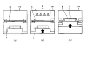
- FIG. 5 is a diagram for explaining the production of a molded product using a resin film as a decorative layer according to the present invention. In the method for producing a molded product of the present invention, first, the decorative layer 8 is preheated (preheating step).
- the preheating temperature of the decoration layer 8 changes with kinds of the resin film to be used, what is necessary is just the temperature which the decoration layer 8 can shape.
- the preheating temperature of the decorative layer 8 is preferably 100 ° C. or higher.
- the porous body 7 and the decorative layer 8 can be thermally welded by heating to the melting point or softening point of the resin or higher. Improves.
- the preheating of the decoration layer 8 can be performed in a furnace whose temperature can be adjusted. In Fig.5 (a), the decoration layer 8 and the plate-shaped porous body 7 are arrange
- the distance from the IR heater 9 to the porous body 7 is set at a position farther than the decorative layer.
- a method of arranging the inside of the furnace in which the porous body 7 exists is set to a temperature lower than the temperature at which the decorative layer 8 is preheated.
- the porous body 7 is pressed against the decorative layer 8, or the decorative layer 8 is pressed against the porous layer 7 to shape the decorative layer 8, and the porous body 7 and the decorative layer 8 are bonded together.
- the method of pressing the decorative layer 8 against the porous body 7 is not particularly limited.
- a method of pressing the decorative layer 8 by physically moving it or a furnace that is a closed space 10 a pressure difference may be generated between the space including the porous body 7 and the space not including the porous body 7 partitioned with the decorative layer 8 as a boundary.
- the pressure difference is generated and pressed, as shown in FIG.
- a method of pressing the space between the porous body 7 and the decorative layer 8 in a vacuum state, the decorative layer 8 For example, there is a method in which compressed air is sent into a space opposite to the porous body 7 and the decorative layer 8 is pressed against the porous body 7. At this time, a vacuum state and a pressurized state may be combined, and a solvent such as water or oil may be used instead of compressed air. In this way, by shaping the decorative layer 8 into the porous body 7 by creating a pressure difference in each space with the decorative layer 8 as a boundary in the closed space, the shapeability to a more complicated shape is achieved. Can be improved, which is preferable.
- the decorative layer 8 can easily enter the porous body 7, and the integration of the porous body 7 and the decorative layer 8 is also strong. Therefore, it is preferable. It is more preferable to perform either or both of shaping and integration by generating a pressure difference in both spaces with the decoration layer 8 as a boundary, and pressure difference between both spaces with the decoration layer 8 as a boundary. It is more preferable that the porous body and the decorative layer are integrated with each other by shaping. Even when the integration is performed by the pressure difference between the two spaces, the integration may be further strengthened by a method described later.
- the porous body 7 is pressed against the decorative layer 8 to shape the decorative layer 8 into a hemispherical shape, but the decorative layer 8 is pressed against the porous body 7 to decorate.
- the layer 8 may be shaped into a hemisphere.
- the pressing force in the shaping integration step may be appropriately selected depending on the preheating temperature of the decorative layer 8 and the porous body 7, but is preferably 1 KN or less.
- the lower limit of the pressing force is not particularly limited, but is preferably 1N or more and more preferably 10N or more from the viewpoint of shaping the decorative layer 8.
- the surface area which anchoring or the porous body 7 and the decoration layer 8 contacts increases, and adhesiveness improves.
- the depth at which the decorative layer 8 penetrates into the porous body 7 is not particularly limited, but the length in the thickness direction of the porous body is preferably 30 ⁇ m or more, more preferably 50 ⁇ m or more, and further 100 ⁇ m or more. preferable.
- the shaping integration step it is preferable to shape the decorative layer 8 while reducing the pressure inside the furnace 10 and integrate it with the porous body 7. If the reinforcing fibers of the porous body 7 enter the decorative layer 8 by forming and integrating under reduced pressure, the adhesion between the porous body 7 and the decorative layer 8 is improved by the anchoring effect. At this time, there is no particular limitation on the length of the reinforcing fibers that have entered the decorative layer 8, but it is preferably 10 ⁇ m or more, more preferably 30 ⁇ m or more, and even more preferably 50 ⁇ m or more.
- the state of the reinforcing fiber that enters the decorative layer 8 is not particularly limited, but 10% or more of the total length of the reinforcing fiber is preferably infiltrated, and more preferably 20% or more is infiltrated.
- the method of depressurization is not particularly limited, but includes a method of depressurizing by operating a vacuum pump or the like, a method of depressurizing a space adjacent to the closed space and opening the connection with the closed space, etc. Can be illustrated. From the viewpoint of stable pressure reduction, the latter method is preferable.
- These pressure reductions can be appropriately set according to the shape of the porous body and the type and thickness of the resin used for the decorative layer. By reducing the pressure from the porous body 7 side, the adhesion between the porous body 7 and the decorative layer 8 can be further improved.
- the integration method is not particularly limited, and examples thereof include a method using an adhesive and a heat welding method.
- the thermal welding method is preferable, and examples thereof include a vibration welding method, an ultrasonic welding method, a laser welding method, and a hot plate welding method. From the viewpoint of adhesiveness and process simplicity, ultrasonic welding and hot plate welding are preferably used.
- the molded article of the present invention produced as described above includes, for example, “a personal computer, a display, an OA device, a mobile phone, a portable information terminal, a PDA (a portable information terminal such as an electronic notebook), a video camera, an optical device, an audio, Cases such as air conditioners, lighting equipment, entertainment equipment, toy goods, and other home appliances, trays, chassis, interior members, diaphragms, speaker cones, or cases thereof, etc., electrical and electronic equipment parts, such as “speaker cones” Acoustic members, "Various members, Various frames, Various hinges, Various arms, Various axles, Various wheel bearings, Various beams", “Hood, Roof, Door, Fender, Trunk lid, Side panel, Rear end panel, Front body, Under Body, various pillars, various members, various frames, various beams, various supports, various rails, various Outer parts such as “hinge” or body parts, “bumper, bumper beam, molding, under cover, engine cover, current plate
- Vf (volume%) (Wf / ⁇ f) / ⁇ Wf / ⁇ f + (Ws ⁇ Wf) / ⁇ r ⁇ ⁇ 100 ⁇ f: density of reinforcing fiber (g / cm 3 ) ⁇ r: Resin density (g / cm 3 )
- Density of molded product ⁇ m A portion including the porous body and the decorative layer was cut out from the molded product as a test piece, and (2) the apparent density of the molded product was measured in the same manner as the density ⁇ of the porous material, and the density ⁇ m was calculated.
- volume content of voids in the porous body A test piece was cut out from the porous body 10 mm in length and 10 mm in width, and the cross section was scanned with a scanning electron microscope (SEM) (S-4800, manufactured by Hitachi High-Technologies Corporation). Observed and photographed 10 locations at equal intervals from the surface of the sample piece at a magnification of 1000 times. For each image, the area Aa of the void in the image was determined. Further, the void ratio was calculated by dividing the void area Aa by the area of the entire image. The volume content of voids in the porous body was determined by arithmetic average from the void ratios at a total of 50 locations, which were taken at 10 locations each with 5 test pieces.
- SEM scanning electron microscope
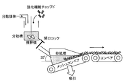
- the reinforcing fiber mat was manufactured using the reinforcing fiber mat manufacturing apparatus shown in FIG. The manufacturing apparatus shown in FIG.
- the papermaking tank includes a mesh conveyor having a papermaking surface having a width of 500 mm at the bottom, and a conveyor capable of transporting a carbon fiber substrate (papermaking substrate) is connected to the mesh conveyor. Papermaking was performed at a carbon fiber concentration of 0.05% by mass in the dispersion.
- the paper-made carbon fiber substrate was dried in a drying furnace at 200 ° C. for 30 minutes to obtain a reinforcing fiber mat having a basis weight of 100 g / m 2 .
- PP resin 100 g of basis weight comprising 80% by mass of unmodified polypropylene resin (“Prime Polypro” (registered trademark) J105G manufactured by Prime Polymer Co., Ltd.) and 20% by mass of acid-modified polypropylene resin (“Admer” QB510 manufactured by Mitsui Chemicals, Inc.) A resin sheet of / m 2 was produced.
- a PET resin film “PICASUS” manufactured by Toray Industries, Inc. was prepared as a decorative layer 8B.
- a shrink film made of polyvinyl chloride resin was prepared as a decorative layer 8C.
- a foamed polypropylene sheet “F-cell” CP3030 manufactured by Furukawa Electric Co., Ltd. was prepared as a foam.
- Porous body 7A The following steps (I) to (V) are performed using a porous body precursor and a press molding die having a press machine hot plate 3 and a die 4 shown in FIG. 3 and capable of producing a flat plate. As a result, a porous body 7A was obtained.
- Porous body 7B A semispherical porous body 7B was obtained in the same manner as the porous body 7A, except that the mold 4 capable of producing a hemispherical shape as shown in FIG. 4 was used.
- Example 1 A porous body 7A was prepared as the porous body 7, and a decorative layer 8A was prepared as the decorative layer 8. As shown in FIG. 5, the porous body 7 was placed in a furnace 10 at a temperature of 80 ° C., and the decorative layer 8 was preheated to 130 ° C. by the IR heater 9 (preheating step). After heating the decorative layer 8, the porous body 7 is pressed against the decorative layer 8 at 0.03 KN to shape the decorative layer 8, and the porous body 7 and the decorative layer 8 are integrated ( Shaped integration step), a molded product was obtained. Table 1 shows the characteristics of the molded product obtained in Example 1.
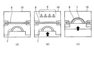
- Example 2 A molded product was obtained as shown in FIG. 6 in the same manner as in Example 1 except that the porous body 7B was used as the porous body 7.
- the properties of the molded product obtained in Example 2 are shown in Table 1.
- Example 3 A porous body 7B was used as the porous body 7, and a decorative layer 8C was used as the decorative layer 8.
- the decorative layer 8 was placed on the porous body 7, and warm air of 150 ° C. was blown with a dryer, and the decorative layer 8 was adhered to the porous body 7. Then, the porous body 7 and the decoration layer 8 were integrated using the ultrasonic welding machine, and the molded article was obtained.
- the properties of the molded product obtained in Example 3 are shown in Table 1.
- Example 4 A molded product was obtained in the same manner as in Example 2 except that the decorative layer 8B was used as the decorative layer 8 and the preheating temperature condition was 160 ° C.
- the properties of the molded product obtained in Example 4 are shown in Table 1.
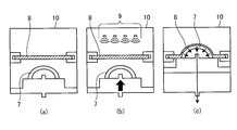
- Example 5 Using the porous body 7A as the porous body 7 and the decorative layer 8A as the decorative layer 8, the space between the porous body 7 and the decorative layer 8 in the furnace 10 is in a vacuum state as shown in FIG. As in Example 1, except that the porous body 7 is pressed against the decorative layer 8 at 0.1 KN, the decorative layer 8 is shaped and the porous body 7 and the decorative layer 8 are integrated. (Molding integration process) to obtain a molded product. The properties of the molded product obtained in Example 5 are shown in Table 1.
- Example 6 A molded product was obtained in the same manner as in Example 5 except that the preheating temperature was 150 ° C.
- the properties of the molded product obtained in Example 6 are shown in Table 1.
- Example 7 Except for using the porous body 7B as the porous body 7, using the decorative layer 8A as the decorative layer 8, and pressing the porous body 7 against the decorative layer 8 at 0.1 KN as shown in FIG.
- the decorative layer 8 is shaped, and the pressure is reduced from the porous body 7 side (the side opposite to the side in contact with the decorative layer 8), so that the porous body 7 and the decorative layer 8 are formed.
- the properties of the molded product obtained in Example 7 are shown in Table 1.
- Comparative Example 1 A molded product was obtained in the same manner as in Example 5 except that a foamed body (independent) composed only of a resin not containing reinforcing fibers was used as the porous body. Table 1 shows the characteristics of the molded product obtained in Comparative Example 1.
- Comparative Example 2 A molded product was obtained in the same manner as in Comparative Example 1 except that a mold for supporting a porous body made of foam (independent) was used. Table 1 shows the characteristics of the molded product obtained in Comparative Example 1.
- Comparative Example 3 A molded product was obtained in the same manner as in Example 2 except that the preheating step for preheating the decorative layer 8 was omitted. Table 1 shows the characteristics of the molded product obtained in Comparative Example 3.
- Comparative Example 4 After the preheating step, a molded product was obtained in the same manner as in Example 2 except that the decorative layer 8 was not pressed against the porous body 7 and placed on the porous body 7 without shaping. . The properties of the molded product obtained in Comparative Example 4 are shown in Table 1.
- the porous body and the decorative layer were integrated together with the shaping of the decorative layer, and thus the productivity was excellent. Moreover, since the porous body which has high compressive strength including another aspect is used, the molded article was able to be obtained without using a type
- Example 6 By increasing the pressing force, reinforcing fibers are added to the decorative layer. Infiltrated and improved adhesion. Moreover, about Example 6, it was also possible to improve the heat-weldability between resin by changing preheating conditions, and to improve adhesiveness.
- Example 7 the decorative layer and the porous body were more firmly integrated by making the decorative layer side of the porous body into a reduced pressure state by reducing the pressure through the porous body. On the other hand, in Comparative Example 1, the porous body was crushed by a high pressing force, and a molded product could not be obtained.
- Comparative Example 2 a mold for shaping and molding was used to prevent the porous body from collapsing, but the porous body was crushed (thinned) in the thickness direction and integrated, but it was necessary. The shape of the molded product could not be obtained.
- Comparative Examples 3 and 4 the adhesion between the porous body and the decorative layer is low, and the decorative layer cannot shape the shape along the porous body, and a necessary molded product can be obtained. There wasn't. From these, it is obvious that the manufacturing method of the molded product of the present application is excellent not only in that the decorative layer can be easily shaped and integrated into the porous body, but also in that the degree of freedom of molding conditions is high. is there.
Abstract
剛性及び軽量性に優れ、意匠性を向上するとともに、生産性に優れた成形品の製造方法を提供する。本発明は、多孔質体の表面に、加飾層を一体化させて得られる成形品の製造方法であって、前記加飾層を予熱する予熱工程と、前記多孔質体を前記加飾層に押し当て、または前記加飾層を前記多孔質体に押し当てて前記加飾層を賦形するとともに、前記多孔質体と前記加飾層を一体化する賦形一体化工程と、を含むことを特徴とする。
Description
本発明は、意匠性および生産性に優れた成形品の製造方法に関するものである。
近年、自動車、航空機、スポーツ製品等の産業用製品については、軽量性の向上に対する市場要求が年々高まっている。このような要求に応えるべく、軽量であり、力学特性に優れる繊維強化複合材料が、各種産業用途に幅広く利用されている。中でも、さらなる軽量化を目的として、樹脂と強化繊維と空隙からなり、力学特性に優れる構造体が提案されている(例えば、特許文献1参照)。
繊維強化複合材料を用いた製品は、意匠性の付与を目的として加飾層を設けることが必要となる場合があるが(例えば、特許文献2参照)、空隙を有する繊維強化複合材料への加飾層の形成については、あまり検討がなされていない状況である。例えば、繊維強化複合材料の表面に樹脂シートが積層された成形品として、繊維強化熱可塑性樹脂シート同士を接着剤で接着し、接着面の反対側の面に熱可塑性樹脂製非通気性フィルムを貼合してなる多層シートを、予熱して厚み方向に膨張させるとともに、中空部を形成した繊維強化熱可塑性樹脂中空体が開示されている(例えば、特許文献3参照)。特許文献3の繊維強化熱可塑性樹脂シート上に接着される熱可塑性樹脂製非通気性フィルムは、繊維強化熱可塑性樹脂シートを真空吸引により成形するために設けられるものであり、加飾層ではないため、意匠性を鑑みるとさらなる加飾層(表皮材)を設けることが必要となる。また、特許文献3の成形方法では、真空吸引による成形であるため、繊維強化熱可塑性樹脂成形品の力学特性にバラツキが出るおそれがある。
また、多孔質体の表面にスキン材を設ける技術も提案されているが(例えば、特許文献4参照)、特許文献4のスキン層は空隙を有するコア層の剛性を向上させることを目的としたものであり、意匠性を鑑みるとさらなる加飾層を設けることが必要となる。さらに、スキン層として連続した強化繊維にマトリックス樹脂を含浸させたプリプレグを使用するため、複雑な構造の成形品では、シワやひび割れが生じるおそれがある。
本発明は、上記に鑑みてなされたものであって、剛性及び軽量性に優れ、意匠性を向上するとともに、生産性に優れる成形品の製造方法を提供することを目的とする。
本発明に係る成形品の製造方法は、強化繊維を有する多孔質体の表面に、加飾層を一体化させて得られる成形品の製造方法であって、前記加飾層を予熱する予熱工程と、前記多孔質体を前記加飾層に押し当て、または前記加飾層を前記多孔質体に押し当てて前記加飾層を賦形するとともに、前記多孔質体と前記加飾層を一体化する賦形一体化工程と、を含む。
また、本発明に係る成形品の製造方法は、強化繊維を有する多孔質体の表面に、加飾層を一体化させて得られる成形品の製造方法であって、前記加飾層を予熱する予熱工程と、前記多孔質体を前記加飾層に押し当て、または前記加飾層を前記多孔質層に押し当てて前記加飾層を賦形する賦形工程と、前記多孔質体と前記加飾層を一体化させる一体化工程と、を含む。
また、本発明に係る成形品の製造方法においては、強化繊維を有する多孔質体の表面に、加飾層を一体化させて成形品を得ることとしており、前記加飾層を予熱する予熱工程と、前記加飾層を前記多孔質体に沿わせて賦形するとともに、前記多孔質体と前記加飾層を一体化させる賦形一体化工程と、を含み、前記加飾層を境界として区画される、前記多孔質体を含む空間と前記多孔質体を含まない空間とを有する閉空間にて、前記両空間の間に圧力差を生じさせることで、前記賦形を行うとともに、前記多孔質体と前記加飾層を一体化する。
また、本発明に係る成形品の製造方法においては、強化繊維を有する多孔質体の表面に、加飾層を一体化させて成形品を得ることとしており、前記加飾層を予熱する予熱工程と、前記加飾層を前記多孔質体に沿わせて賦形する賦形工程と、前記多孔質体と前記加飾層を一体化させる一体化工程と、を含み、前記加飾層を境界として区画される、前記多孔質体を含む空間と前記多孔質体を含まない空間とを有する閉空間にて、前記両空間の間に圧力差を生じさせることで、前記賦形工程および一体化工程の一方または両方を行う。
本発明に係る成形品の製造方法によれば、多孔質体の力学特性にバラツキが出るおそれがない。また、加飾層の予備賦形プロセスおよび金型が不要となり、生産性に優れる成形品を得ることができる。
以下、本発明に係る成形品の製造方法について説明する。
本発明に係る成形品の製造方法は、強化繊維を有する多孔質体の表面に、加飾層を一体化させて得られる成形品の製造方法であって、前記加飾層を予熱する予熱工程と、前記多孔質体を前記加飾層に押し当て、または前記加飾層を前記多孔質体に押し当てて前記加飾層を賦形するとともに、前記多孔質体と前記加飾層を一体化する賦形一体化工程と、を含むことを特徴とする。
本発明に係る成形品の製造方法は、強化繊維を有する多孔質体の表面に、加飾層を一体化させて得られる成形品の製造方法であって、前記加飾層を予熱する予熱工程と、前記多孔質体を前記加飾層に押し当て、または前記加飾層を前記多孔質体に押し当てて前記加飾層を賦形するとともに、前記多孔質体と前記加飾層を一体化する賦形一体化工程と、を含むことを特徴とする。
(多孔質体)
本発明の成形品において、多孔質体は、強化繊維に加え、さらに樹脂と、空隙と、を有することが好ましい。
本発明の成形品において、多孔質体は、強化繊維に加え、さらに樹脂と、空隙と、を有することが好ましい。
本発明の多孔質体において、強化繊維としては、アルミニウム、黄銅、ステンレス等の金属繊維、PAN系、レーヨン系、リグニン系、ピッチ系の炭素繊維、黒鉛繊維、ガラス等の絶縁性繊維、アラミド、PBO、ポリフェニレンスルフィド、ポリエステル、アクリル、ナイロン、ポリエチレン等の有機繊維、シリコンカーバイト、シリコンナイトライド等の無機繊維を例示できる。また、これらの繊維に表面処理が施されているものであってもよい。表面処理としては、導電体として金属の被着処理の他に、カップリング剤による処理、サイジング剤による処理、結束剤による処理、添加剤の付着処理等がある。また、これらの繊維は1種類を単独で用いてもよいし、2種類以上を併用してもよい。中でも、軽量化効果の観点から、比強度、比剛性に優れるPAN系、ピッチ系、レーヨン系等の炭素繊維が好ましく用いられる。また、得られる多孔質体の経済性を高める観点からは、ガラス繊維が好ましく用いられ、とりわけ力学特性と経済性とのバランスから炭素繊維とガラス繊維とを併用することが好ましい。さらに、得られる多孔質体の衝撃吸収性や賦形性を高める観点からは、アラミド繊維が好ましく用いられ、とりわけ力学特性と衝撃吸収性とのバランスから炭素繊維とアラミド繊維とを併用することが好ましい。また、得られる多孔質体の導電性を高める観点からは、導電性を有する金属からなる金属繊維やニッケルや銅やイッテルビウム等の金属を被覆した強化繊維を用いることもできる。これらの中で、強度と弾性率等の力学特性に優れる金属繊維、ピッチ系炭素繊維、及びPAN系炭素繊維からなる群より選ばれる強化繊維をより好ましく用いることができる。
強化繊維は、不連続であり、多孔質体中にランダムに分散していることが好ましい。また分散状態が略モノフィラメント状であることがより好ましい。強化繊維をかかる態様とすることで、シート状の多孔質体の前駆体を、外力を加えて成形する場合に、複雑形状への賦型が容易となる。また、強化繊維をかかる態様とすることで、強化繊維によって形成された空隙が緻密化し、多孔質体中における強化繊維の繊維束端における弱部が極小化できるため、優れた補強効率及び信頼性に加えて、等方性も付与される。
ここで、略モノフィラメント状とは、強化繊維単糸が500本未満の細繊度ストランドにて存在することを指す。さらに好ましくは、モノフィラメント状、つまり単糸として分散していることである。
ここで、略モノフィラメント状、又は、モノフィラメント状に分散しているとは、多孔質体中にて任意に選択した強化繊維について、その二次元配向角が1°以上である単繊維の割合(以下、繊維分散率とも称す)が80%以上であることを指し、言い換えれば、多孔質体中において単繊維の2本以上が接触して平行した束が20%未満であることをいう。従って、ここでは、少なくとも強化繊維におけるフィラメント数100本以下の繊維束の質量分率が100%に該当するものが特に好ましい。
さらに、強化繊維はランダムに分散していることが、とりわけ好ましい。ここで、強化繊維がランダムに分散しているとは、多孔質体中において任意に選択した強化繊維の二次元配向角の算術平均値が30°以上、60°以下の範囲内にあることをいう。かかる二次元配向角とは、強化繊維の単繊維とこの単繊維と交差する単繊維とで形成される角度のことであり、交差する単繊維同士が形成する角度のうち、0°以上、90°以下の範囲内にある鋭角側の角度と定義する。
この二次元配向角について、図面を用いてさらに説明する。図1(a),(b)において、単繊維1aを基準とすると、単繊維1aは他の単繊維1b~1fと交差している。ここで、交差とは、観察する二次元平面において、基準とする単繊維が他の単繊維と交わって観察される状態のことを意味し、単繊維1aと単繊維1b~1fとが必ずしも接触している必要はなく、投影して見た場合に交わって観察される状態についても例外ではない。つまり、基準となる単繊維1aについて見た場合、単繊維1b~1fの全てが二次元配向角の評価対象であり、図1(a)中において二次元配向角は交差する2つの単繊維が形成する2つの角度のうち、0°以上、90°以下の範囲内にある鋭角側の角度である。
二次元配向角を測定する方法としては、特に制限はないが、例えば、構成要素の表面から強化繊維の配向を観察する方法を例示できる。二次元配向角の平均値は、次の手順で測定する。すなわち、無作為に選択した単繊維(図1における単繊維1a)に対して交差している全ての単繊維(図1における単繊維1b~1f)との二次元配向角の平均値を測定する。例えば、ある単繊維に交差する別の単繊維が多数の場合には、交差する別の単繊維を無作為に20本選び測定した算術平均値を代用してもよい。この測定を別の単繊維を基準として合計5回繰り返し、その算術平均値を二次元配向角の算術平均値として算出する。
強化繊維が略モノフィラメント状、且つ、ランダムに分散していることで、上述した略モノフィラメント状に分散した強化繊維により与えられる性能を最大限まで高めることができる。また、多孔質体において力学特性に等方性を付与できる。かかる観点から、強化繊維の繊維分散率は90%以上であることが好ましく、100%に近づくほどより好ましい。また、強化繊維の二次元配向角の算術平均値は、40°以上、50°以下の範囲内にあることが好ましく、理想的な角度である45°に近づくほど好ましい。二次元配向角の好ましい範囲としては、上記した上限のいずれの値を上限としてもよく、上記した下限のいずれの値を下限としてもよい。
一方、強化繊維が不連続状の形態をとらない例としては、強化繊維が一方向に配列されてなるシート基材、織物基材、及びノンクリンプ基材等がある。これらの形態は、強化繊維が規則的に密に配置されるため、多孔質体中の空隙が少なくなってしまい、樹脂の含浸が極めて困難となり、未含浸部を形成したり、含浸手段や樹脂種の選択肢を大きく制限したりする場合がある。
強化繊維の形態としては、多孔質体と同程度の長さの連続性強化繊維、又は、所定長に切断された有限長の不連続性強化繊維のいずれであってもよいが、樹脂を容易に含浸させたり、その量を容易に調整できたりする観点からは、不連続性強化繊維であることが好ましい。
本発明の多孔質体において、強化繊維の質量平均繊維長が1mm以上15mm以下の範囲内にあることが好ましい。これにより、強化繊維の補強効率を高めることができ、多孔質体に優れた力学特性を与えられる。強化繊維の質量平均繊維長が1mm以上である場合、多孔質体中の空隙を効率よく形成できるため、密度を低くすることが可能となり、言い換えれば、同一の厚さでありながら軽量な多孔質体を得ることができるので好ましい。一方、強化繊維の質量平均繊維長が15mm以下の場合には、多孔質体中で強化繊維が、自重により屈曲しにくくなり、力学特性の発現を阻害しないため好ましい。質量平均繊維長は、多孔質体の樹脂成分を焼失や溶出等の方法により取り除き、残った強化繊維から無作為に400本を選択し、その長さを10μm単位まで測定し、それらの質量平均繊維長として算出できる。
強化繊維は不織布状の形態をとることが、強化繊維への樹脂の含浸の容易さの観点から好ましい。さらに、強化繊維が、不織布状の形態を有していることにより、不織布自体のハンドリング性の容易さに加え、一般的に高粘度とされる熱可塑性樹脂の場合においても含浸を容易なものとできるため好ましい。ここで、不織布状の形態とは、強化繊維のストランド及び/又はモノフィラメントが規則性なく面状に分散した形態を指し、チョップドストランドマット、コンティニュアンスストランドマット、抄紙マット、カーディングマット、エアレイドマット等を例示できる(以下、これらをまとめて強化繊維マットと称す)。
本発明の多孔質体において、樹脂としては、熱可塑性樹脂や熱硬化性樹脂を例示できる。また、本発明においては、熱硬化性樹脂と熱可塑性樹脂とがブレンドされていてもよい。樹脂は、多孔質体および多孔質体の前駆体を構成するマトリックス樹脂となる。
本発明における1つの形態において、樹脂は、少なくとも1種類以上の熱可塑性樹脂を含むことが好ましい。熱可塑性樹脂としては、「ポリエチレンテレフタレート(PET)、ポリブチレンテレフタレート(PBT)、ポリトリメチレンテレフタレート(PTT)、ポリエチレンナフタレート(PEN)、液晶ポリエステル等のポリエステル、ポリエチレン(PE)、ポリプロピレン(PP)、ポリブチレン等のポリオレフィン、ポリオキシメチレン(POM)、ポリアミド(PA)、ポリフェニレンスルフィド(PPS)等のポリアリーレンスルフィド、ポリケトン(PK)、ポリエーテルケトン(PEK)、ポリエーテルエーテルケトン(PEEK)、ポリエーテルケトンケトン(PEKK)、ポリエーテルニトリル(PEN)、ポリテトラフルオロエチレン等のフッ素系樹脂、液晶ポリマー(LCP)」等の結晶性樹脂、「スチレン系樹脂の他、ポリカーボネート(PC)、ポリメチルメタクリレート(PMMA)、ポリ塩化ビニル(PVC)、ポリフェニレンエーテル(PPE)、ポリイミド(PI)、ポリアミドイミド(PAI)、ポリエーテルイミド(PEI)、ポリサルホン(PSU)、ポリエーテルサルホン、ポリアリレート(PAR)」等の非晶性樹脂、その他、フェノール系樹脂、フェノキシ樹脂、さらにポリスチレン系、ポリオレフィン系、ポリウレタン系、ポリエステル系、ポリアミド系、ポリブタジエン系、ポリイソプレン系、フッ素系樹脂、及びアクリロニトリル系等の熱可塑エラストマー等や、これらの共重合体及び変性体等から選ばれる熱可塑性樹脂を例示できる。中でも、得られる多孔質体の軽量性の観点からはポリオレフィンが好ましく、強度の観点からはポリアミドが好ましく、表面外観の観点からポリカーボネートやスチレン系樹脂のような非晶性樹脂が好ましく、耐熱性の観点からポリアリーレンスルフィドが好ましく、連続使用温度の観点からポリエーテルエーテルケトンが好ましく、さらに耐薬品性の観点からフッ素系樹脂が好ましく用いられる。
本発明における1つの形態において、樹脂は、少なくとも1種類以上の熱硬化性樹脂を含むことが好ましい。熱硬化性樹脂としては、不飽和ポリエステル、ビニルエステル、エポキシ樹脂、フェノール樹脂、ユリア樹脂、メラミン樹脂、熱硬化性ポリイミド、これらの共重合体、変性体、及びこれらの少なくとも2種類をブレンドした樹脂を例示できる。
また、本発明の目的を損なわない範囲で、本発明に係る多孔質体は樹脂の成分の1つとして、エラストマー又はゴム成分等の耐衝撃性向上剤、他の充填材や添加剤を含有してもよい。充填材や添加剤の例としては、無機充填材、難燃剤、導電性付与剤、結晶核剤、紫外線吸収剤、酸化防止剤、制振剤、抗菌剤、防虫剤、防臭剤、着色防止剤、熱安定剤、離型剤、帯電防止剤、可塑剤、滑剤、着色剤、顔料、染料、発泡剤、制泡剤、又は、カップリング剤を例示できる。
本発明の多孔質体は、空隙を有する。本発明における空隙とは、樹脂により被覆された強化繊維が柱状の支持体となり、それが重なり合い、又は、交差することにより形成された空間のことを指す。例えば強化繊維に樹脂が予め含浸された多孔質体の前駆体を加熱して多孔質体を得る場合、加熱に伴う樹脂の溶融ないしは軟化により、強化繊維が起毛することで空隙が形成される。これは、多孔質体の前駆体において、加圧により圧縮状態とされていた内部の強化繊維が、その弾性率に由来する起毛力によって起毛する性質に基づく。空隙は、少なくとも厚み方向に連続している。
本発明の多孔質体は、強化繊維の体積含有率(%)が、0.5~55体積%、樹脂の体積含有率(%)が、2.5~85体積%、空隙の体積含有率(%)が、10~97体積%であることが好ましい。
多孔質体において、強化繊維の体積含有率が0.5体積%以上である場合、強化繊維に由来する補強効果を十分なものとすることができるので好ましい。一方、強化繊維の体積含有率が55体積%以下の場合には、強化繊維に対する樹脂の体積含有率が相対的に多くなり、多孔質体中の強化繊維同士を結着し、強化繊維の補強効果を十分なものとできるため、多孔質体の力学特性、とりわけ曲げ特性を満足できるので好ましい。
多孔質体において、樹脂の体積含有率が2.5体積%以上である場合、多孔質体中の強化繊維同士を結着し、強化繊維の補強効果を十分なものとすることができ、多孔質体の力学特性、とりわけ曲げ弾性率を満足できるので好ましい。一方、樹脂の体積含有率が85体積%以下であれば、空隙の形成を阻害しないため好ましい。
多孔質体において、強化繊維は樹脂に被覆されており、被覆している樹脂の厚み(被覆厚み)が1μm以上、15μm以下の範囲内にあることが好ましい。樹脂に被覆された強化繊維の被覆状態は、少なくとも多孔質体を構成する強化繊維の単繊維同士の交差する点が被覆されていれば、多孔質体の形状安定性や、厚み制御の容易さ及び自由度の観点から十分であるが、さらに好ましい態様とすれば、樹脂は、強化繊維の周囲に、上述の厚みで被覆された状態であることが好ましい。この状態は、強化繊維の表面が樹脂によって露出していない、言い換えれば、強化繊維が樹脂により電線状の皮膜を形成していることを意味する。このことにより、多孔質体は、さらに、形状安定性を有すると共に、力学特性の発現を十分なものとする。また、樹脂に被覆された強化繊維の被覆状態は、その強化繊維の全てにおいて被覆されている必要はなく、本発明に係る多孔質体の形状安定性や、曲げ弾性率、曲げ強度を損なわない範囲内であればよい。
多孔質体において、空隙の体積含有率は、10体積%以上97体積%以下の範囲内であることが好ましい。空隙の含有率が10体積%以上であることにより、多孔質体の密度が低くなるため軽量性を満足できるため好ましい。一方、空隙の含有率が97体積%以下の場合には、言い換えれば、強化繊維の周囲に被覆された樹脂の厚みが十分なものとなることから、多孔質体中における強化繊維同士の補強を十分に行うことができ、力学特性が高くなるので好ましい。空隙の体積含有率の上限値は97体積%であることが好ましい。本発明において、体積含有率は多孔質体を構成する強化繊維と、樹脂と、空隙のそれぞれの体積含有率の合計を100体積%とする。
多孔質体において、空隙は、多孔質体の前駆体の樹脂の粘度を低下させることにより、強化繊維が起毛し、元の状態に戻ろうとする復元力によって形成される。これにより強化繊維は樹脂(熱可塑性樹脂または熱硬化性樹脂)を介して結合することにより、より強固な圧縮特性と多孔質体の形状保持性を発現することから好ましい。
多孔質体の密度ρは0.9g/cm3以下であることが好ましい。多孔質体の密度ρが0.9g/cm3以下の場合、多孔質体とした場合の質量が減少することを意味し、結果、製品とした場合の質量の軽量化に貢献することとなるので好ましい。より好ましくは0.7g/cm3以下、さらに好ましくは0.5g/cm3以下である。密度の下限については制限を設けないが、一般的に強化繊維と樹脂とを有する多孔質体では、その構成成分である強化繊維、樹脂、及び空隙それぞれの体積割合から算出される値が下限となり得る。本発明に係る成形品においては、多孔質体自身の密度は、使用する強化繊維や樹脂により異なるが、多孔質体の力学特性を保持するという観点から、0.03g/cm3以上であることが好ましい。
多孔質体のJIS K7220で測定される50%圧縮時の圧縮強度は、1MPa以上であることが好ましい。圧縮強度が1MPa以上であることにより、多孔質体は形状保持性に優れるため、加飾層に多孔質体を押し当て、または加飾層を多孔質体に押し当てて、加飾層を賦形することができる。圧縮強度は、1MPa以上あれば実用上問題ないが、好ましくは3MPa以上である。
また、多孔質体の表面粗さRa1は、200μm以下であることが好ましい。多孔質体の表面粗さRa1を200μm以下とすることにより、成形品の表面粗さRa2を、所望する範囲とすることが可能となる。加飾層と多孔質体の付着性を強固とする観点より、機械的なアンカリングの形成を容易とするために10μm以上であることが好ましく、より好ましくは30μm以上、さらに好ましくは50μm以上である。
多孔質体の空隙は、少なくとも厚み方向に連続していることが好ましい。空隙が厚み方向に連続することにより、多孔質体は通気性を有することができる。多孔質体が通気性を有する場合、多孔質体と加飾層とを一体化する際に、多孔質体の加飾層と接する面と反対側から減圧して、一体化することができる。このような方法の場合、多孔質体を介して(多孔質体内の空隙を通じて)減圧して一体化されるため、加飾層の多孔質体への付着性を向上することができる。
(加飾層)
本発明の成形品において、加飾層とは、成形品を最終製品として提供可能とすることを目的とした意匠性を付与するフィルム状からなる層である。フィルム状のものとしては、樹脂製、金属製、木材などが挙げられる。中でも、樹脂製のフィルムが好ましく、印刷塗装、真空蒸着、着色等で加飾された樹脂フィルムがより好ましい。
本発明の成形品において、加飾層とは、成形品を最終製品として提供可能とすることを目的とした意匠性を付与するフィルム状からなる層である。フィルム状のものとしては、樹脂製、金属製、木材などが挙げられる。中でも、樹脂製のフィルムが好ましく、印刷塗装、真空蒸着、着色等で加飾された樹脂フィルムがより好ましい。
加飾層のベースとなる樹脂は、熱可塑性樹脂を使用することができる。熱可塑性樹脂としては、特に限定されるものではないが、ポリエチレンテレフタレート(PET)、アクリル樹脂(MMA)、ポリカーボネート(PC)、ポリオレフィン(PO)、アクリロニトリルブタジエンスチレン樹脂(ABS)等任意の熱可塑性樹脂を用いることができる。また、加飾層を形成する樹脂フィルムは、単一層だけでなく、例えば、MMA/PC、MMA/PC/MMA等、複数層有する樹脂フィルムも使用することができる。また多孔質体を構成する熱可塑性樹脂と同様に選択することができる。
加飾層は、上記の樹脂に加え、目的に応じて添加剤を有していてもよい。
添加剤は、添加剤としては特に限定はされないが、成形品に対し、着色ならびにパール感やメタリック感をはじめとした意匠性を付与することを目的として添加される。
また、添加剤としては、顔料やガラスビーズなどが挙げられる。具体的にはアゾ顔料、フタロシアニンブルーなどの有機顔料、アルミニウム、真鍮などの金属粉末からなる金属顔料、酸化クロム、コバルトブルーなどの無機顔料が挙げられる。なかでも、耐熱性の観点から金属顔料、無機顔料が好ましい。また、強化繊維が炭素繊維やアラミド繊維など濃色である場合には、屈折率が異なる構造を2層以上有する顔料が好ましく用いられる。例えば、酸化チタンや酸化鉄で被覆した天然マイカ、人工マイカ、アルミナフレーク、シリカフレーク、ガラスフレークである。かかる層構造とすることにより、可視光領域の光の干渉、回折、散乱といった光学現象によって発色させることができる。光の干渉、回折、散乱といった光学現象を利用すると、特定波長の光の反射によって発色できるため、濃色の強化繊維を用いた場合に、好ましく用いられる。
また、加飾層および成形品の質量増加を抑制する観点から、中空形状の添加剤を使用することもできる。中空形状の添加剤としては、中空ガラスビーズやポーラスな樹脂粒子などが軽量化の点で好ましい。
添加剤は、球状、繊維状、フレーク状の形態であってよい。添加時の最大寸法は、200μm以下であることが好ましい。ここで、添加剤の最大寸法とは、添加剤の一次粒子の最大寸法または添加剤が凝集等する場合は二次粒子の最大寸法を意味するものである。添加剤の最大寸法が200μm以下であることにより、加飾層の表面が平滑となり、意匠性が向上する。添加剤の最大寸法は、電子顕微鏡を用いて添加剤を観察し、寸法が少なくとも1μm単位まで測定可能な画像となるように拡大した画像から、無作為に任意の100個の添加剤を選び、それぞれの添加剤の外側輪郭線上の任意の2点を、その距離が最大になるように選んだときの長さを最大長さとして計測した値の平均値である。
添加剤の最大寸法は、より好ましくは150μm以下であり、さらに好ましくは100μm以下である。添加剤の最大寸法の下限は、1μm以上が好ましく、さらに好ましくは5μm以上であり、より好ましくは10μm以上である。
(成形品)
本発明の成形品において、加飾層の厚みは10μm以上500μm以下であることが好ましい。厚みが10μmより薄い場合、賦形一体化工程において加飾フィルムを加飾層に賦形した際に、加飾層が形状を維持することが困難となる場合がある。また、厚みを500μmより厚くした場合、平滑な面や意匠性に優れた面を形成は可能であるが、成形品の質量が増加してしまい、成形品の軽量性を発言することが困難となる。さらに好ましくは、加飾層の厚みは50μm以上400μm以下である。
本発明の成形品において、加飾層の厚みは10μm以上500μm以下であることが好ましい。厚みが10μmより薄い場合、賦形一体化工程において加飾フィルムを加飾層に賦形した際に、加飾層が形状を維持することが困難となる場合がある。また、厚みを500μmより厚くした場合、平滑な面や意匠性に優れた面を形成は可能であるが、成形品の質量が増加してしまい、成形品の軽量性を発言することが困難となる。さらに好ましくは、加飾層の厚みは50μm以上400μm以下である。
本発明の成形品において、成形品の加飾層の表面粗さRa2は、100μm以下であることが好ましい。表面粗さRa2が100μm以下であることにより、表面が平滑となり、より好ましくは50μm以下、さらに好ましくは30μm以下とすることで、より優れた意匠性を有する成形品を得ることができる。
本発明の成形品において、密度ρは1.0g/cm3以下であることが好ましい。成形品の密度ρが1.0g/cm3以下の場合、成形品の質量が減少、すなわち、製品とした場合の質量の軽量化に貢献することとなるので好ましい。より好ましくは0.8g/cm3以下、さらに好ましくは0.6g/cm3以下である。密度の下限については制限を設けないが、一般的に強化繊維と樹脂とを有する多孔質体と、主として樹脂からなる加飾層を有する成形品では、その構成成分である強化繊維、樹脂、及び空隙それぞれの体積割合から算出される値が下限となり得る。本発明に係る成形品においては、成形品の密度は、使用する強化繊維や樹脂により異なるが、成形品の力学特性を保持するという観点から、0.05g/cm3以上であることが好ましい。
(多孔質体の製造)
多孔質体の前駆体、および多孔質体の製造方法について説明する。
多孔質体の前駆体、および多孔質体の製造方法について説明する。
前駆体を製造する方法としては、強化繊維マットに溶融ないし軟化した状態の樹脂を加圧または減圧する方法が挙げられる。具体的には、強化繊維マットの厚み方向の両側および/または中心から樹脂を配置した積層物を、加熱、加圧して樹脂を溶融含浸させる方法が製造の容易さの観点から好ましく例示できる。
多孔質体を構成する強化繊維マットの製造方法としては、例えば強化繊維を予めストランド及び/又は略モノフィラメント状に分散して強化繊維マットを製造する方法がある。強化繊維マットの製造方法としては、強化繊維を空気流にて分散シート化するエアレイド法や、強化繊維を機械的に櫛削りながら形状を整えシート化するカーディング法等の乾式プロセス、強化繊維を水中にて攪拌して抄紙するラドライト法による湿式プロセスを公知
技術として挙げることができる。強化繊維をよりモノフィラメント状に近づける手段としては、乾式プロセスにおいては、開繊バーを設ける方法やさらに開繊バーを振動させる方法、さらにカードの目をファインにする方法や、カードの回転速度を調整する方法等を例示できる。湿式プロセスにおいては、強化繊維の攪拌条件を調整する方法、分散液の強化繊維濃度を希薄化する方法、分散液の粘度を調整する方法、分散液を移送させる際に渦流を抑制する方法等を例示できる。特に、強化繊維マットは湿式プロセスで製造することが好ましく、投入繊維の濃度を増やしたり、分散液の流速(流量)とメッシュコンベアの速度を調整したりすることで強化繊維マットの強化繊維の割合を容易に調整できる。例えば、分散液の流速に対してメッシュコンベアの速度を遅くすることで、得られる強化繊維マット中の繊維の配向が引き取り方向に向き難くなり、嵩高い強化繊維マットを製造可能である。強化繊維マットは、強化繊維単体から構成されていてもよく、強化繊維が粉末形状や繊維形状のマトリックス樹脂成分と混合されていたり、強化繊維が有機化合物や無機化合物と混合されていたり、強化繊維同士が樹脂成分で目留めされていてもよい。
技術として挙げることができる。強化繊維をよりモノフィラメント状に近づける手段としては、乾式プロセスにおいては、開繊バーを設ける方法やさらに開繊バーを振動させる方法、さらにカードの目をファインにする方法や、カードの回転速度を調整する方法等を例示できる。湿式プロセスにおいては、強化繊維の攪拌条件を調整する方法、分散液の強化繊維濃度を希薄化する方法、分散液の粘度を調整する方法、分散液を移送させる際に渦流を抑制する方法等を例示できる。特に、強化繊維マットは湿式プロセスで製造することが好ましく、投入繊維の濃度を増やしたり、分散液の流速(流量)とメッシュコンベアの速度を調整したりすることで強化繊維マットの強化繊維の割合を容易に調整できる。例えば、分散液の流速に対してメッシュコンベアの速度を遅くすることで、得られる強化繊維マット中の繊維の配向が引き取り方向に向き難くなり、嵩高い強化繊維マットを製造可能である。強化繊維マットは、強化繊維単体から構成されていてもよく、強化繊維が粉末形状や繊維形状のマトリックス樹脂成分と混合されていたり、強化繊維が有機化合物や無機化合物と混合されていたり、強化繊維同士が樹脂成分で目留めされていてもよい。
上記各方法を実現するための設備としては、圧縮成形機やダブルベルトプレスを好適に用いることができる。バッチ式の場合は前者であり、加熱用と冷却用との2機以上を並列した間欠式プレスシステムとすることで生産性の向上が図れる。連続式の場合は後者であり、連続的な加工を容易に行うことができるので連続生産性に優れる。
続いて、前駆体を膨張させて多孔質体に成形する工程としては、特に限定はされないが、多孔質体を構成する樹脂の粘度を低下させることで多孔質体に成形することが好ましい。樹脂の粘度を低下させる方法としては、前駆体を加熱することが好ましい。加熱方法については、特に限定されないが、所望の温度に設定した金型や熱板などに接触させて加熱する方法や、ヒーターなどを用いた非接触状態で加熱する方法が上げられる。多孔質体を構成する樹脂として熱可塑性樹脂を使用する場合、融点または軟化点以上に加熱すればよく、熱硬化性樹脂を使用する場合、硬化反応が開始する温度より低い温度で加熱する。
多孔質体の厚み制御を行う方法としては、加熱される前駆体を目的の厚みに制御できれば方法によらないが、金属板等を用いて厚みを拘束する方法、前駆体に付与する圧力により厚み制御する方法等が製造の簡便さの観点から好ましい方法として例示される。上記方法を実現するための設備としては、圧縮成形機やダブルベルトプレスを好適に用いることができる。バッチ式の場合は前者であり、加熱用と冷却用の2機以上を並列した間欠式プレスシステムとすることで生産性の向上が図れる。連続式の場合は後者であり、連続的な加工を容易に行うことができるため連続生産性に優れる。
(成形品の製造)
多孔質体に加飾層を形成する方法としては、特に限定はされないが、樹脂フィルムなどの加飾層を金型内に配置し、多孔質体を投入するといったインモールド成形や樹脂フィルムなどの加飾層を多孔質体に押し当てるまたは多孔質体を加飾層に押し当てるといったようなアウトモールド成形が挙げられる。本発明で特に用いられる方法は、アウトモールド成形である。図5は、本発明に係る加飾層として樹脂フィルムを用いた成形品の製造を説明する図である。本発明の成形品の製造方法では、まず、加飾層8を予熱する(予熱工程)。加飾層8の予熱温度は、使用する樹脂フィルムの種類により異なるが、加飾層8が賦形可能な温度であればよい。加飾層8の予熱温度は、好ましくは100℃以上である。なお、成形品の樹脂と加飾層の樹脂が同一種の場合、樹脂の融点または軟化点以上に加熱することにより、多孔質体7と加飾層8とを熱溶着することができ、接着性が向上する。加飾層8の予熱は、温度調整可能な炉等で行うことができる。図5(a)では、温度調整可能な炉10内に加飾層8および板状の多孔質体7を配置して、加飾層8および多孔質体7を予熱している。
多孔質体に加飾層を形成する方法としては、特に限定はされないが、樹脂フィルムなどの加飾層を金型内に配置し、多孔質体を投入するといったインモールド成形や樹脂フィルムなどの加飾層を多孔質体に押し当てるまたは多孔質体を加飾層に押し当てるといったようなアウトモールド成形が挙げられる。本発明で特に用いられる方法は、アウトモールド成形である。図5は、本発明に係る加飾層として樹脂フィルムを用いた成形品の製造を説明する図である。本発明の成形品の製造方法では、まず、加飾層8を予熱する(予熱工程)。加飾層8の予熱温度は、使用する樹脂フィルムの種類により異なるが、加飾層8が賦形可能な温度であればよい。加飾層8の予熱温度は、好ましくは100℃以上である。なお、成形品の樹脂と加飾層の樹脂が同一種の場合、樹脂の融点または軟化点以上に加熱することにより、多孔質体7と加飾層8とを熱溶着することができ、接着性が向上する。加飾層8の予熱は、温度調整可能な炉等で行うことができる。図5(a)では、温度調整可能な炉10内に加飾層8および板状の多孔質体7を配置して、加飾層8および多孔質体7を予熱している。
多孔質体7の予熱は必ずしも行う必要はないが、加飾層8の賦形性、多孔質体7との接着性を向上することができるので、多孔質体7を予熱することが好ましい。このとき、多孔質体7を、上記した予熱工程における加飾層8の予熱温度以下の温度に予熱することが好ましい。加飾層8の予熱温度を多孔質体7の予熱温度より高くする場合には、図5(b)に示すように、IRヒーター9等により行うことができる。一方、多孔質体7の温度を加飾層8の予熱温度以下に予熱する方法としては、図5に示すようにIRヒーター9から多孔質体7までの距離を加飾層よりも遠い位置に配置する方法や多孔質体7が存在する炉内を加飾層8が予熱される温度よりも低い温度に設定するなどが挙げられる。
続いて、多孔質体7を加飾層8に押し当て、または加飾層8を多孔質層7に押し当てて加飾層8を賦形するとともに、多孔質体7と加飾層8を一体化する(賦形一体化工程)。加飾層8を多孔質体7に押し当てる方法としては、特に限定されないが、例えば、図5(c)に示すように物理的に位置を移動させて押し当てる方法や、閉空間である炉10において、加飾層8を境界として区画される多孔質体7を含む空間と多孔質体7を含まない空間との間に圧力差を生じさせて押し当ててもよい。圧力差を生じさせて押し当てる場合の例としては、図7(c)に示すように、多孔質体7と加飾層8の間の空間を真空状態として押し当てる方法、加飾層8を挟んで多孔質体7と反対側の空間に圧縮空気を送り込み多孔質体7に加飾層8を押し当てる方法などがある。このとき、真空状態と加圧状態を組み合わせても良く、圧縮空気の代わりに水や油などの溶媒を用いても良い。このように、閉空間において加飾層8を境界とした各空間に圧力差を生じさせることによって加飾層8を多孔質体7に賦形することで、より複雑な形状への賦形性を向上させることができるため、好ましい。同様に加飾層8を境界とした両空間に圧力差を生じさせることによって、加飾層8が多孔質体7に浸入しやすくなり、多孔質体7と加飾層8の一体化も強固になるため、好ましい。加飾層8を境界とした両空間に圧力差を生じさせることによって、賦形または一体化のいずれか一方または両方を行うことがより好ましく、加飾層8を境界とした両空間に圧力差を生じさせることによって、賦形するとともに多孔質体と加飾層を一体化することがさらに好ましい。なお、上記両空間の圧力差により上記一体化を行う場合でも、後述の方法で一体化をより強固にしてもよい。
図6(c)では、多孔質体7を加飾層8に押し当てて加飾層8を半球状に賦形しているが、加飾層8を多孔質体7に押し当てて加飾層8を半球状に賦形してもよい。賦形一体化工程における押し当て力は、加飾層8および多孔質体7の予熱温度により適宜選択すればよいが、1KN以下であることが好ましい。押し当て力の下限については特に限定されないが、加飾層8を形状賦形する観点から1N以上であることが好ましく、10N以上であることがより好ましい。賦形一体化工程において、加飾層8が多孔質体7に侵入することが好ましい。このような状態とすることで、アンカリングや多孔質体7と加飾層8の接する表面積が増加し、接着性が向上する。このとき、加飾層8が多孔質体7に侵入している深さは特に限定されないが、多孔質体の厚み方向の長さとして30μm以上が好ましく、50μm以上がより好ましく、100μm以上がさらに好ましい。
また、賦形一体化工程において、炉10内を減圧等しながら加飾層8を賦形し、多孔質体7と一体化させることが好ましい。減圧下で賦形一体化することにより、加飾層8に多孔質体7の強化繊維が浸入すればそのアンカリング効果で多孔質体7と加飾層8の接着性が向上する。このとき、加飾層8に強化繊維が浸入している長さについては特に限定はされないが、10μm以上が好ましく、30μm以上がより好ましく、50μm以上がさらに好ましい。また、加飾層8に浸入する強化繊維の状態は特に限定されないが、強化繊維の全長の10%以上が浸入していることが好ましく、20%以上が浸入されていることがより好ましい。なお、多孔質体7の加飾層8と接する面側と反対側から減圧することが、さらに好ましい。減圧の方法については特に限定はされないが、真空ポンプなどを稼動させることによって減圧する方法や、閉空間に隣接する空間を減圧状態としておき、閉空間との接続を開通することで減圧する方法などが例示できる。安定した減圧をする観点から、後者の方法が好ましい。加飾層の賦形性や多孔質体との一体化を高める観点からは、減圧の度合いを急激に変化させて加飾層が容易に変形可能な状態で賦形工程および一体化工程の一方または両方を行うことが好ましい。軽量性などを考慮して厚みの薄い加飾層を破れなく形成する観点からは、減圧の度合いを緩やかに変化させて賦形工程および一体化工程の一方または両方を行うことが好ましい。これらの減圧は、多孔質体の形状や加飾層に用いる樹脂の種類や厚みに応じて適宜設定することができる。多孔質体7側から減圧することにより、多孔質体7と加飾層8の接着性をさらに向上することができる。
本発明において、加飾層8の賦形と、加飾層8と多孔質体7との一体化を同時に行うことが好ましいが、多孔質体を加飾層に押し当て、または加飾層を多孔質層に押し当てて加飾層を賦形する賦形工程後、多孔質体と加飾層を一体化させてもよい。一体化の方法としては、特に限定はされないが、接着剤を用いる方法、熱溶着方法が挙げられる。中でも、熱溶着法方が好ましく、振動溶着法、超音波溶着法、レーザー溶着法、熱板溶着法などを例示できる。接着性や工程の簡易性の観点から、超音波溶着法および熱板溶着法が好ましく用いられる。
以上のようにして製造した本発明の成形品は、例えば、「パソコン、ディスプレイ、OA機器、携帯電話、携帯情報端末、PDA(電子手帳等の携帯情報端末)、ビデオカメラ、光学機器、オーディオ、エアコン、照明機器、娯楽用品、玩具用品、その他家電製品等の筐体、トレイ、シャーシ、内装部材、振動板、スピーカーコーン、またはそのケース」等の電気、電子機器部品、「スピーカーコーン」等の音響部材、「各種メンバ、各種フレーム、各種ヒンジ、各種アーム、各種車軸、各種車輪用軸受、各種ビーム」、「フード、ルーフ、ドア、フェンダ、トランクリッド、サイドパネル、リアエンドパネル、フロントボディー、アンダーボディー、各種ピラー、各種メンバ、各種フレーム、各種ビーム、各種サポート、各種レール、各種ヒンジ」等の、外板、又は、ボディー部品、「バンパー、バンパービーム、モール、アンダーカバー、エンジンカバー、整流板、スポイラー、カウルルーバー、エアロパーツ」等の外装部品、「インストルメントパネル、シートフレーム、ドアトリム、ピラートリム、ハンドル、各種モジュール」等の内装部品、又は、「モーター部品、CNGタンク、ガソリンタンク」等の自動車、二輪車用構造部品、「バッテリートレイ、ヘッドランプサポート、ペダルハウジング、プロテクター、ランプリフレクター、ランプハウジング、ノイズシールド、スペアタイヤカバー」等の自動車、二輪車用部品、「遮音壁、防音壁などの壁内部材」等の建材、「ランディングギアポッド、ウィングレット、スポイラー、エッジ、ラダー、エレベーター、フェイリング、リブ、シート」等の航空機用部品に好適に使用することができる。力学特性および形状賦型性の観点からは、自動車内外装、電気・電子機器筐体、自転車、スポーツ用品用構造材、航空機内装材、輸送用箱体、建材に好ましく用いられる。
以下、実施例により本発明をさらに詳細に説明する。
(1)多孔質体における強化繊維の体積含有率Vf
多孔質体から試験片を切り出し、質量Wsを測定した後、試験片を空気中500℃で30分間加熱して樹脂成分を焼き飛ばし、残った強化繊維の質量Wfを測定し、次式により算出した。このとき、強化繊維および樹脂の密度は、JIS Z8807(2012)の液中ひょう量法に従って測定した結果を用いる。
Vf(体積%)=(Wf/ρf)/{Wf/ρf+(Ws-Wf)/ρr}×100
ρf:強化繊維の密度(g/cm3)
ρr:樹脂の密度(g/cm3)
多孔質体から試験片を切り出し、質量Wsを測定した後、試験片を空気中500℃で30分間加熱して樹脂成分を焼き飛ばし、残った強化繊維の質量Wfを測定し、次式により算出した。このとき、強化繊維および樹脂の密度は、JIS Z8807(2012)の液中ひょう量法に従って測定した結果を用いる。
Vf(体積%)=(Wf/ρf)/{Wf/ρf+(Ws-Wf)/ρr}×100
ρf:強化繊維の密度(g/cm3)
ρr:樹脂の密度(g/cm3)
(2)多孔質体の密度ρ
多孔質体から試験片として切り出し、JIS K7222(2005)を参考にして多孔質体の見かけ密度を測定した。試験片の寸法は縦100mm、横100mmとした。試験片の縦、横、厚みをマイクロメーターで測定し、得られた値より試験片の体積Vを算出した。また、切り出した試験片の質量Mを電子天秤で測定した。得られた質量M及び体積Vを次式に代入することにより多孔質体の密度ρを算出した。
ρ[g/cm3]=M[g]/V[cm3]
多孔質体から試験片として切り出し、JIS K7222(2005)を参考にして多孔質体の見かけ密度を測定した。試験片の寸法は縦100mm、横100mmとした。試験片の縦、横、厚みをマイクロメーターで測定し、得られた値より試験片の体積Vを算出した。また、切り出した試験片の質量Mを電子天秤で測定した。得られた質量M及び体積Vを次式に代入することにより多孔質体の密度ρを算出した。
ρ[g/cm3]=M[g]/V[cm3]
(3)成形品の密度ρm
成形品から多孔質体および加飾層を含む部分を試験片として切り出し、(2)多孔質体の密度ρと同様にして成形品の見かけ密度を測定し、密度ρmを算出した。
成形品から多孔質体および加飾層を含む部分を試験片として切り出し、(2)多孔質体の密度ρと同様にして成形品の見かけ密度を測定し、密度ρmを算出した。
(4)多孔質体の空隙の体積含有率
多孔質体から縦10mm、横10mmに試験片を切り出し、断面を走査型電子顕微鏡(SEM)((株)日立ハイテクノロジーズ製 S-4800型)により観察し、試料片の表面から、等間隔に10箇所を1000倍の倍率で撮影した。それぞれの画像について、画像内の空隙の面積Aaを求めた。さらに、空隙の面積Aaを画像全体の面積で除算することにより空隙率を算出した。多孔質体の空隙の体積含有率は、5枚の試験片でそれぞれ10箇所ずつ撮影した合計50箇所の空隙率から算術平均により求めた。
多孔質体から縦10mm、横10mmに試験片を切り出し、断面を走査型電子顕微鏡(SEM)((株)日立ハイテクノロジーズ製 S-4800型)により観察し、試料片の表面から、等間隔に10箇所を1000倍の倍率で撮影した。それぞれの画像について、画像内の空隙の面積Aaを求めた。さらに、空隙の面積Aaを画像全体の面積で除算することにより空隙率を算出した。多孔質体の空隙の体積含有率は、5枚の試験片でそれぞれ10箇所ずつ撮影した合計50箇所の空隙率から算術平均により求めた。
(5)多孔質体と加飾層の状態観察
(4)と同様に、成形品から試験片を切り出し、試験片をエポキシ樹脂で包埋、研磨して断面をレーザー顕微鏡で観察した。このとき、加飾層が多孔質体(特に表面に形成される孔、厚み方向に連続した空隙)に浸入しているか、加飾層に多孔質体を構成する強化繊維が浸入しているかを観察した。
(4)と同様に、成形品から試験片を切り出し、試験片をエポキシ樹脂で包埋、研磨して断面をレーザー顕微鏡で観察した。このとき、加飾層が多孔質体(特に表面に形成される孔、厚み方向に連続した空隙)に浸入しているか、加飾層に多孔質体を構成する強化繊維が浸入しているかを観察した。
(6)多孔質体の表面粗さRa1および成形品の表面粗さRa2
多孔質体または成形品について、表面粗さ計を用いて、JIS-B0601(2001)に基づき、カットオフ値および基準長さを選定し、表面粗さRa1(μm)およびRa2(μm)を求めた。
多孔質体または成形品について、表面粗さ計を用いて、JIS-B0601(2001)に基づき、カットオフ値および基準長さを選定し、表面粗さRa1(μm)およびRa2(μm)を求めた。
(7)多孔質体の通気性(厚み方向への通気性)
下記(a)~(d)により多孔質体の通気性を測定した。JIS規格で試験条件の上限とされている500Paまでに通気を確認できたものは「通気性あり」と判断、それ以外は、「通気性なし」と判断した。
(a)多孔質体から100mm×100mm、厚み5mmの試験片を切り出す(5mm以下であればそのまま。5mmよりも厚い場合は、切削加工などにより厚みを調整する。)。
(b)試験片の端部(カット面)を4面テープで覆う(厚み方向と垂直方向への通気を防ぐため。)。
(c)JIS L1096(2010) A法(フラジール法)が測定可能な試験機の円筒の一端に試験片を取り付ける。
(d)傾斜形気圧計が500Pa以下の圧力となるように吸込みファンおよび空気孔を調整する。
(8)多孔質体の圧縮強度試験
多孔質体から25mm×25mmの試験片を切り出し、JIS K7220(2006)を参考にして多孔質体の圧縮強度を万能試験機を用いて測定した。この時、変形率50%時に到達した最大の力Fmと試験片の試験前の底面断面積A0とを用いて、次式より圧縮強さσmを算出した。測定装置としては“インストロン(登録商標)”5565型万能材料試験機(インストロン・ジャパン(株)製)を使用した。
σm[kPa]=103×Fm[N]/A0[mm2]
多孔質体から25mm×25mmの試験片を切り出し、JIS K7220(2006)を参考にして多孔質体の圧縮強度を万能試験機を用いて測定した。この時、変形率50%時に到達した最大の力Fmと試験片の試験前の底面断面積A0とを用いて、次式より圧縮強さσmを算出した。測定装置としては“インストロン(登録商標)”5565型万能材料試験機(インストロン・ジャパン(株)製)を使用した。
σm[kPa]=103×Fm[N]/A0[mm2]
(9)加飾層と多孔質体との付着性
JIS K5600-5-6(1999)塗料一般試験方法-塗膜の機械的性質―付着性(クロスカット法)に準じて加飾層の付着性を評価した。試料をレーザー顕微鏡(キーエンス(株)製、VK-9510)で400倍に拡大し、観察を行った。観察画像を汎用画像解析ソフトウェア上に展開し、ソフトウェアに組み込まれたプログラムを利用して観察画像中に見える加飾層が剥がれた面積を求めた。JIS K5600-5-6の表1の試験結果の分類の0~3を良好、4~5を不良と判定した。
JIS K5600-5-6(1999)塗料一般試験方法-塗膜の機械的性質―付着性(クロスカット法)に準じて加飾層の付着性を評価した。試料をレーザー顕微鏡(キーエンス(株)製、VK-9510)で400倍に拡大し、観察を行った。観察画像を汎用画像解析ソフトウェア上に展開し、ソフトウェアに組み込まれたプログラムを利用して観察画像中に見える加飾層が剥がれた面積を求めた。JIS K5600-5-6の表1の試験結果の分類の0~3を良好、4~5を不良と判定した。
下記の実施例および比較例において、以下の材料を使用した。
[強化繊維マット1]
東レ(株)製“トレカ”T700S-12Kをカートリッジカッターで5mmにカットし、チョップド炭素繊維を得た。水と界面活性剤(ナカライテクス(株)製、ポリオキシエチレンラウリルエーテル(商品名))とからなる濃度0.1質量%の分散液を作製し、この分散液とチョップド炭素繊維とを用いて図2に示す強化繊維マットの製造装置を用いて、強化繊維マットを製造した。図2に示す製造装置は、分散槽としての容器下部に開口コックを有する直径1000mmの円筒形状の容器、分散槽と抄紙槽とを接続する直線状の輸送部(傾斜角30°)を備えている。分散槽の上面の開口部には撹拌機が付属し、開口部からチョップド炭素繊維及び分散液(分散媒体)を投入可能である。抄紙槽が、底部に幅500mmの抄紙面を有するメッシュコンベアを備え、炭素繊維基材(抄紙基材)を運搬可能なコンベアをメッシュコンベアに接続している。抄紙は分散液中の炭素繊維濃度を0.05質量%として行った。抄紙した炭素繊維基材は200℃の乾燥炉で30分間乾燥し、目付けが100g/m2の強化繊維マットを得た。
[PP樹脂]
未変性ポリプロピレン樹脂(プライムポリマー(株)製“プライムポリプロ”(登録商標)J105G)80質量%と、酸変性ポリプロピレン樹脂(三井化学(株)製“アドマー”QB510)20質量%とからなる目付100g/m2の樹脂シートを作製した。
未変性ポリプロピレン樹脂(プライムポリマー(株)製“プライムポリプロ”(登録商標)J105G)80質量%と、酸変性ポリプロピレン樹脂(三井化学(株)製“アドマー”QB510)20質量%とからなる目付100g/m2の樹脂シートを作製した。
[加飾層8A]
出光ユニテック(株)製PP樹脂フィルム「ピュアサーモ」を、加飾層8Aとして準備した。
出光ユニテック(株)製PP樹脂フィルム「ピュアサーモ」を、加飾層8Aとして準備した。
[加飾層8B]
東レ(株)製PET樹脂フィルム「PICASUS」を、加飾層8Bとして準備した。
[加飾層8C]
ポリ塩化ビニル樹脂製のシュリンクフィルムを、加飾層8Cとして準備した。
東レ(株)製PET樹脂フィルム「PICASUS」を、加飾層8Bとして準備した。
[加飾層8C]
ポリ塩化ビニル樹脂製のシュリンクフィルムを、加飾層8Cとして準備した。
[発泡体]
古河電気工業(株)製発泡ポリプロピレンシート「エフセル」CP3030を発泡体として準備した。
古河電気工業(株)製発泡ポリプロピレンシート「エフセル」CP3030を発泡体として準備した。
[多孔質体の前駆体]
強化繊維マットとして強化繊維マット1、樹脂シートとしてPP樹脂を、[樹脂シート/強化繊維マット/樹脂シート/強化繊維マット/強化繊維マット/樹脂シート/強化繊維マット/樹脂シート]の順番に配置した積層物を作製した。次いで、以下の工程(I)~(IV)を経ることにより多孔質体の前駆体を得た。
工程(I):積層物を200℃に予熱したプレス成形用金型キャビティ内に配置して金型を閉じる。
工程(II):次いで、3MPaの圧力を付与し、180秒間保持する。
工程(III):工程(II)の後、圧力を保持した状態でキャビティ温度を50℃まで冷却する。
工程(IV):金型を開いて多孔質体の前駆体を取り出す。
強化繊維マットとして強化繊維マット1、樹脂シートとしてPP樹脂を、[樹脂シート/強化繊維マット/樹脂シート/強化繊維マット/強化繊維マット/樹脂シート/強化繊維マット/樹脂シート]の順番に配置した積層物を作製した。次いで、以下の工程(I)~(IV)を経ることにより多孔質体の前駆体を得た。
工程(I):積層物を200℃に予熱したプレス成形用金型キャビティ内に配置して金型を閉じる。
工程(II):次いで、3MPaの圧力を付与し、180秒間保持する。
工程(III):工程(II)の後、圧力を保持した状態でキャビティ温度を50℃まで冷却する。
工程(IV):金型を開いて多孔質体の前駆体を取り出す。
[多孔質体7A]
多孔質体の前駆体および図3に示す、プレス機熱板3、金型4を有し、平板を作製可能なプレス成形用金型を用い、以下の工程(I)~(V)を経ることにより多孔質体7Aを得た。
工程(I):多孔質体の前駆体5を260℃に設定したIRヒーターで60秒間予熱した。
工程(II):予熱後、前駆体5を120℃に設定したプレス成形用金型キャビティ内に配置した。このとき、多孔質体の厚みを調整するための金属のスペーサー6を挿入した。
工程(III):次いで、プレス機熱板3により3MPaの圧力を付与して60秒間保持する。
工程(IV):その後、圧力を保持した状態でキャビティ温度を50℃まで冷却する。
工程(V):金型4を開いて多孔質体を取り出す。
[多孔質体7B]
図4に示すような半球状を作製可能な金型4を用いること以外は、多孔質体7Aと同様にして半球状の多孔質体7Bを得た。
図4に示すような半球状を作製可能な金型4を用いること以外は、多孔質体7Aと同様にして半球状の多孔質体7Bを得た。
(実施例1)
多孔質体7として多孔質体7A、加飾層8として加飾層8Aを準備した。図5に示すように、温度を80℃とした炉10内に多孔質体7を配置し、IRヒーター9により加飾層8を130℃まで予熱した(予熱工程)。加飾層8の加熱後、多孔質体7を加飾層8に0.03KNで押し当てて、加飾層8を賦形するとともに、多孔質体7と加飾層8とを一体化し(賦形一体化工程)、成形品を得た。実施例1で得た成形品の特性を表1に示す。
多孔質体7として多孔質体7A、加飾層8として加飾層8Aを準備した。図5に示すように、温度を80℃とした炉10内に多孔質体7を配置し、IRヒーター9により加飾層8を130℃まで予熱した(予熱工程)。加飾層8の加熱後、多孔質体7を加飾層8に0.03KNで押し当てて、加飾層8を賦形するとともに、多孔質体7と加飾層8とを一体化し(賦形一体化工程)、成形品を得た。実施例1で得た成形品の特性を表1に示す。
(実施例2)
多孔質体7として多孔質体7Bを用いたこと以外は実施例1と同様にして、図6に示すようにして成形品を得た。実施例2で得た成形品の特性を表1に示す。
多孔質体7として多孔質体7Bを用いたこと以外は実施例1と同様にして、図6に示すようにして成形品を得た。実施例2で得た成形品の特性を表1に示す。
(実施例3)
多孔質体7として多孔質体7B、加飾層8として加飾層8Cを用いた。多孔質体7に加飾層8をかぶせ、ドライヤーで150℃の温風を吹き付け、加飾層8を多孔質体7に密着させた。その後、超音波溶着機を用いて、多孔質体7と加飾層8を一体化して成形品を得た。実施例3で得た成形品の特性を表1に示す。
多孔質体7として多孔質体7B、加飾層8として加飾層8Cを用いた。多孔質体7に加飾層8をかぶせ、ドライヤーで150℃の温風を吹き付け、加飾層8を多孔質体7に密着させた。その後、超音波溶着機を用いて、多孔質体7と加飾層8を一体化して成形品を得た。実施例3で得た成形品の特性を表1に示す。
(実施例4)
加飾層8として加飾層8Bを使用し、予熱温度条件を160℃とした以外は実施例2と同様にして、成形品を得た。実施例4で得た成形品の特性を表1に示す。
加飾層8として加飾層8Bを使用し、予熱温度条件を160℃とした以外は実施例2と同様にして、成形品を得た。実施例4で得た成形品の特性を表1に示す。
(実施例5)
多孔質体7として前記多孔質体7A、加飾層8として加飾層8Aを用い、図7に示すように、炉10内の多孔質体7と加飾層8の間の空間を真空状態として多孔質体7を加飾層8に0.1KNで押し当てること以外は実施例1と同様にして、加飾層8を賦形するとともに、多孔質体7と加飾層8とを一体化し(賦形一体化工程)、成形品を得た。実施例5で得た成形品の特性を表1に示す。
多孔質体7として前記多孔質体7A、加飾層8として加飾層8Aを用い、図7に示すように、炉10内の多孔質体7と加飾層8の間の空間を真空状態として多孔質体7を加飾層8に0.1KNで押し当てること以外は実施例1と同様にして、加飾層8を賦形するとともに、多孔質体7と加飾層8とを一体化し(賦形一体化工程)、成形品を得た。実施例5で得た成形品の特性を表1に示す。
(実施例6)
予熱温度を150℃とした以外は実施例5と同様にして、成形品を得た。実施例6で得た成形品の特性を表1に示す。
予熱温度を150℃とした以外は実施例5と同様にして、成形品を得た。実施例6で得た成形品の特性を表1に示す。
(実施例7)
多孔質体7として多孔質体7Bを用い、加飾層8として加飾層8Aを用い、図8に示すように、多孔質体7を加飾層8に0.1KNで押し当てること以外は実施例2と同様にして、加飾層8を賦形するとともに、多孔質体7側(加飾層8と接する面側と反対側)から減圧して、多孔質体7と加飾層8とを一体化し(賦形一体化工程)、成形品を得た。実施例7で得た成形品の特性を表1に示す。
多孔質体7として多孔質体7Bを用い、加飾層8として加飾層8Aを用い、図8に示すように、多孔質体7を加飾層8に0.1KNで押し当てること以外は実施例2と同様にして、加飾層8を賦形するとともに、多孔質体7側(加飾層8と接する面側と反対側)から減圧して、多孔質体7と加飾層8とを一体化し(賦形一体化工程)、成形品を得た。実施例7で得た成形品の特性を表1に示す。
(比較例1)
強化繊維を含まない樹脂のみからなる発泡体(独立)を多孔質体として用いること以外は実施例5と同様にして、成形品を得た。比較例1で得た成形品の特性を表1に示す。
強化繊維を含まない樹脂のみからなる発泡体(独立)を多孔質体として用いること以外は実施例5と同様にして、成形品を得た。比較例1で得た成形品の特性を表1に示す。
(比較例2)
発泡体(独立)からなる多孔質体を支持する型を使用すること以外は、比較例1と同様にして、成形品を得た。比較例1で得た成形品の特性を表1に示す。
(比較例3)
加飾層8を予熱する予熱工程を省くこと以外は、実施例2と同様にして、成形品を得た。比較例3で得た成形品の特性を表1に示す。
(比較例4)
予熱工程の後、加飾層8を多孔質体7に押し当てず、賦形することなく多孔質体7の上に配置したこと以外は、実施例2と同様にして、成形品を得た。比較例4で得た成形品の特性を表1に示す。
発泡体(独立)からなる多孔質体を支持する型を使用すること以外は、比較例1と同様にして、成形品を得た。比較例1で得た成形品の特性を表1に示す。
(比較例3)
加飾層8を予熱する予熱工程を省くこと以外は、実施例2と同様にして、成形品を得た。比較例3で得た成形品の特性を表1に示す。
(比較例4)
予熱工程の後、加飾層8を多孔質体7に押し当てず、賦形することなく多孔質体7の上に配置したこと以外は、実施例2と同様にして、成形品を得た。比較例4で得た成形品の特性を表1に示す。
〔検討〕
本実施例で示された成形品の製造方法では、加飾層の賦形とともに多孔質体と加飾層を一体化するため、生産性に優れたものであった。また別の様態も含め、高い圧縮強度を有する多孔質体を用いるため、型を使用せずに成形品を得ることができた。実施例1~3について、簡易な設備においても多孔質体の表面に加飾層を形成することが可能な点で優れる。実施例4について、多孔質体と加飾層の樹脂が異なる場合にも、多孔質体に加飾層を形成することが可能であった。実施例5について、押し当て力を高めた真空成形においても、多孔質体がつぶれることなく、加飾層を形成することが可能であり、押し当て力を高めたことにより加飾層に強化繊維が浸入し、付着性を高めることができた。また実施例6について、予熱条件を変更することによって樹脂同士の熱溶着性を高め、付着性を高めることも可能であった。実施例7において、多孔質体を介して減圧することにより、多孔質体の加飾層側を減圧状態とすることで、より強固に加飾層と多孔質体が一体化された。一方、比較例1においては、高い押し当て力によって多孔質体がつぶれてしまい、成形品を得ることが出来なかった。また比較例2において、多孔質体のつぶれを防止するために賦形一体化成形用の型を用いたが、多孔質体が厚み方向につぶれ(薄くなり)、一体化はできたが必要な成形品の形状を得ることは出来なかった。比較例3および4においては、多孔質体と加飾層の接着性が低く、加飾層が多孔質体に沿った形状を賦形することもできず、必要な成形品を得ることが出来なかった。これらより、本願の成形品の製造方法は、多孔質体に加飾層を容易に賦形・一体化可能なだけでなく、成形条件の自由度が高いという点でも優れていることは明白である。
本実施例で示された成形品の製造方法では、加飾層の賦形とともに多孔質体と加飾層を一体化するため、生産性に優れたものであった。また別の様態も含め、高い圧縮強度を有する多孔質体を用いるため、型を使用せずに成形品を得ることができた。実施例1~3について、簡易な設備においても多孔質体の表面に加飾層を形成することが可能な点で優れる。実施例4について、多孔質体と加飾層の樹脂が異なる場合にも、多孔質体に加飾層を形成することが可能であった。実施例5について、押し当て力を高めた真空成形においても、多孔質体がつぶれることなく、加飾層を形成することが可能であり、押し当て力を高めたことにより加飾層に強化繊維が浸入し、付着性を高めることができた。また実施例6について、予熱条件を変更することによって樹脂同士の熱溶着性を高め、付着性を高めることも可能であった。実施例7において、多孔質体を介して減圧することにより、多孔質体の加飾層側を減圧状態とすることで、より強固に加飾層と多孔質体が一体化された。一方、比較例1においては、高い押し当て力によって多孔質体がつぶれてしまい、成形品を得ることが出来なかった。また比較例2において、多孔質体のつぶれを防止するために賦形一体化成形用の型を用いたが、多孔質体が厚み方向につぶれ(薄くなり)、一体化はできたが必要な成形品の形状を得ることは出来なかった。比較例3および4においては、多孔質体と加飾層の接着性が低く、加飾層が多孔質体に沿った形状を賦形することもできず、必要な成形品を得ることが出来なかった。これらより、本願の成形品の製造方法は、多孔質体に加飾層を容易に賦形・一体化可能なだけでなく、成形条件の自由度が高いという点でも優れていることは明白である。

本発明によれば、剛性及び軽量性に優れ、意匠性を備えた成形品の生産性を向上することができる。
1 強化繊維
1a~1f 単繊維
2 二次元配向角
3 プレス機熱板
4 金型
5 前駆体
6 スペーサー
7 多孔質体
8 加飾層
9 IRヒーター
10 炉
1a~1f 単繊維
2 二次元配向角
3 プレス機熱板
4 金型
5 前駆体
6 スペーサー
7 多孔質体
8 加飾層
9 IRヒーター
10 炉
Claims (16)
- 強化繊維を有する多孔質体の表面に、加飾層を一体化させて得られる成形品の製造方法であって、
前記加飾層を予熱する予熱工程と、
前記多孔質体を前記加飾層に押し当て、または前記加飾層を前記多孔質体に押し当てて前記加飾層を賦形するとともに、前記多孔質体と前記加飾層を一体化する賦形一体化工程と、
を含む成形品の製造方法。 - 前記賦形一体化工程における押し当て力が1KN以下である、請求項1に記載の成形品の製造方法。
- 強化繊維を有する多孔質体の表面に、加飾層を一体化させて得られる成形品の製造方法であって、
前記加飾層を予熱する予熱工程と、
前記多孔質体を前記加飾層に押し当て、または前記加飾層を前記多孔質体に押し当てて前記加飾層を賦形する賦形工程と、
前記多孔質体と前記加飾層を一体化させる一体化工程と、
を含む成形品の製造方法。 - 強化繊維を有する多孔質体の表面に、加飾層を一体化させて得られる成形品の製造方法であって、
前記加飾層を予熱する予熱工程と、
前記加飾層を前記多孔質体に沿わせて賦形するとともに、前記多孔質体と前記加飾層を一体化させる賦形一体化工程と、を含み、
前記加飾層を境界として区画される、前記多孔質体を含む空間と前記多孔質体を含まない空間とを有する閉空間にて、前記両空間の間に圧力差を生じさせることで、前記賦形を行うとともに、前記多孔質体と前記加飾層を一体化する、成形品の製造方法。 - 強化繊維を有する多孔質体の表面に、加飾層を一体化させて得られる成形品の製造方法であって、
前記加飾層を予熱する予熱工程と、
前記加飾層を前記多孔質体に沿わせて賦形する賦形工程と、
前記多孔質体と前記加飾層を一体化させる一体化工程と、を含み、
前記加飾層を境界として区画される、前記多孔質体を含む空間と前記多孔質体を含まない空間とを有する閉空間にて、前記両空間の間に圧力差を生じさせることで、前記賦形工程および一体化工程の一方または両方を行う、成形品の製造方法。 - 前記多孔質体を、前記予熱工程の温度以下の温度に予熱する工程を含む、請求項1~5のいずれかに記載の成形品の製造方法。
- 前記多孔質体の表面粗さRa1が200μm以下である、請求項1~6のいずれかに記載の成形品の製造方法。
- 前記成形品の表面粗さRa2が100μm以下である、請求項1~7のいずれかに記載の成形品の製造方法。
- 前記多孔質体がさらに樹脂と空隙とを有する、請求項1~8のいずれかに記載の成形品の製造方法。
- 前記多孔質体が厚み方向に連続した空隙を有する、請求項1~9のいずれかに記載の成形品の製造方法。
- 前記多孔質体の圧縮強度が1MPa以上である、請求項1~10のいずれかに記載の成形品の製造方法。
- 前記多孔質体の密度が0.1~1.0g/cm3である、請求項1~11のいずれかに記載の成形品の製造方法。
- 前記多孔質体と前記加飾層が熱溶着されている、請求項1~12のいずれかに記載の成形品の製造方法。
- 前記加飾層が前記多孔質体に浸入している、請求項1~13のいずれかに記載の成形品の製造方法。
- 前記加飾層に前記強化繊維が浸入している、請求項1~14のいずれかに記載の成形品の製造方法。
- 前記賦形一体化工程または前記一体化工程においては、前記多孔質体の加飾層と接する面側と反対側から減圧して、前記多孔質体と前記加飾層側を一体化する、請求項1~15のいずれかに記載の成形品の製造方法。
Priority Applications (5)
| Application Number | Priority Date | Filing Date | Title |
|---|---|---|---|
| US16/976,838 US20210001536A1 (en) | 2018-03-30 | 2019-03-28 | Method for manufacturing molded article |
| JP2019517998A JP7294131B2 (ja) | 2018-03-30 | 2019-03-28 | 成形品の製造方法 |
| KR1020207026698A KR20200132876A (ko) | 2018-03-30 | 2019-03-28 | 성형품의 제조 방법 |
| EP19775044.1A EP3778195B1 (en) | 2018-03-30 | 2019-03-28 | Method for manufacturing molded article |
| CN201980021904.3A CN111936301B (zh) | 2018-03-30 | 2019-03-28 | 成型品的制造方法 |
Applications Claiming Priority (2)
| Application Number | Priority Date | Filing Date | Title |
|---|---|---|---|
| JP2018-069182 | 2018-03-30 | ||
| JP2018069182 | 2018-03-30 |
Publications (1)
| Publication Number | Publication Date |
|---|---|
| WO2019189582A1 true WO2019189582A1 (ja) | 2019-10-03 |
Family
ID=68060293
Family Applications (1)
| Application Number | Title | Priority Date | Filing Date |
|---|---|---|---|
| PCT/JP2019/013619 WO2019189582A1 (ja) | 2018-03-30 | 2019-03-28 | 成形品の製造方法 |
Country Status (7)
| Country | Link |
|---|---|
| US (1) | US20210001536A1 (ja) |
| EP (1) | EP3778195B1 (ja) |
| JP (1) | JP7294131B2 (ja) |
| KR (1) | KR20200132876A (ja) |
| CN (1) | CN111936301B (ja) |
| TW (1) | TW201945157A (ja) |
| WO (1) | WO2019189582A1 (ja) |
Cited By (1)
| Publication number | Priority date | Publication date | Assignee | Title |
|---|---|---|---|---|
| CN111730850A (zh) * | 2020-06-18 | 2020-10-02 | 江苏汤臣新材料科技有限公司 | 一种有机玻璃半球形结构均匀压制模具及其压制方法 |
Families Citing this family (2)
| Publication number | Priority date | Publication date | Assignee | Title |
|---|---|---|---|---|
| JP7043510B2 (ja) * | 2017-03-21 | 2022-03-29 | マグナ エクステリアーズ インコーポレイテッド | 2つのヒンジのインモールドアセンブリ |
| DE102021006465A1 (de) | 2021-12-29 | 2023-06-29 | Demmel Aktiengesellschaft | Hinterleuchtetes Fahrzeug-Zierteil, insbesondere Fahrzeug-Emblem |
Citations (6)
| Publication number | Priority date | Publication date | Assignee | Title |
|---|---|---|---|---|
| JPS6123965B2 (ja) | 1980-09-30 | 1986-06-09 | Nippon Kuraisu Kk | |
| JPH09254248A (ja) | 1996-03-21 | 1997-09-30 | Sumitomo Chem Co Ltd | 繊維強化熱可塑性樹脂中空成形体およびその製造方法 |
| JP2001150587A (ja) * | 1999-11-30 | 2001-06-05 | Sumitomo Chem Co Ltd | 積層パネル |
| WO2015029634A1 (ja) | 2013-08-30 | 2015-03-05 | 東レ株式会社 | サンドイッチ構造体、それを用いた一体化成形品およびそれらの製造方法 |
| JP2016078451A (ja) | 2014-10-17 | 2016-05-16 | 東レ株式会社 | 繊維強化複合材料の製造方法、樹脂基材およびプリフォーム |
| JP2018047681A (ja) * | 2016-09-16 | 2018-03-29 | 山本印刷株式会社 | 加飾樹脂シートを備えた成形品とその製造方法 |
Family Cites Families (7)
| Publication number | Priority date | Publication date | Assignee | Title |
|---|---|---|---|---|
| CN1082882C (zh) * | 1994-03-04 | 2002-04-17 | 阿马塞尔有限公司 | 制造结构性制品的方法和器械 |
| JPH08238705A (ja) * | 1995-03-07 | 1996-09-17 | Sumitomo Chem Co Ltd | 衝撃吸収部品 |
| CN1914024B (zh) * | 2004-01-26 | 2011-06-29 | 沙伯基础创新塑料知识产权有限公司 | 结构增强的树脂制品及其制备方法 |
| US7837911B2 (en) * | 2004-01-26 | 2010-11-23 | Sabic Innovative Plastics Ip B.V. | Methods of forming a layered article |
| DE102011000336B9 (de) * | 2011-01-26 | 2012-11-29 | Novem Car Interior Design Gmbh | Verfahren zur Herstellung eines Formteils mittels Tiefziehen |
| US20140147630A1 (en) * | 2011-07-12 | 2014-05-29 | Riken Technos Corporation | Molded article coated with a film |
| JP6462547B2 (ja) * | 2015-10-02 | 2019-01-30 | 天昇電気工業株式会社 | 樹脂成形品および樹脂成形品の製造方法 |
-
2019
- 2019-03-28 EP EP19775044.1A patent/EP3778195B1/en active Active
- 2019-03-28 JP JP2019517998A patent/JP7294131B2/ja active Active
- 2019-03-28 US US16/976,838 patent/US20210001536A1/en not_active Abandoned
- 2019-03-28 CN CN201980021904.3A patent/CN111936301B/zh active Active
- 2019-03-28 KR KR1020207026698A patent/KR20200132876A/ko unknown
- 2019-03-28 WO PCT/JP2019/013619 patent/WO2019189582A1/ja active Application Filing
- 2019-03-29 TW TW108111147A patent/TW201945157A/zh unknown
Patent Citations (6)
| Publication number | Priority date | Publication date | Assignee | Title |
|---|---|---|---|---|
| JPS6123965B2 (ja) | 1980-09-30 | 1986-06-09 | Nippon Kuraisu Kk | |
| JPH09254248A (ja) | 1996-03-21 | 1997-09-30 | Sumitomo Chem Co Ltd | 繊維強化熱可塑性樹脂中空成形体およびその製造方法 |
| JP2001150587A (ja) * | 1999-11-30 | 2001-06-05 | Sumitomo Chem Co Ltd | 積層パネル |
| WO2015029634A1 (ja) | 2013-08-30 | 2015-03-05 | 東レ株式会社 | サンドイッチ構造体、それを用いた一体化成形品およびそれらの製造方法 |
| JP2016078451A (ja) | 2014-10-17 | 2016-05-16 | 東レ株式会社 | 繊維強化複合材料の製造方法、樹脂基材およびプリフォーム |
| JP2018047681A (ja) * | 2016-09-16 | 2018-03-29 | 山本印刷株式会社 | 加飾樹脂シートを備えた成形品とその製造方法 |
Non-Patent Citations (1)
| Title |
|---|
| See also references of EP3778195A4 |
Cited By (1)
| Publication number | Priority date | Publication date | Assignee | Title |
|---|---|---|---|---|
| CN111730850A (zh) * | 2020-06-18 | 2020-10-02 | 江苏汤臣新材料科技有限公司 | 一种有机玻璃半球形结构均匀压制模具及其压制方法 |
Also Published As
| Publication number | Publication date |
|---|---|
| EP3778195A1 (en) | 2021-02-17 |
| EP3778195B1 (en) | 2023-07-12 |
| JPWO2019189582A1 (ja) | 2021-02-12 |
| KR20200132876A (ko) | 2020-11-25 |
| JP7294131B2 (ja) | 2023-06-20 |
| CN111936301B (zh) | 2023-04-04 |
| CN111936301A (zh) | 2020-11-13 |
| TW201945157A (zh) | 2019-12-01 |
| EP3778195A4 (en) | 2021-12-01 |
| US20210001536A1 (en) | 2021-01-07 |
Similar Documents
| Publication | Publication Date | Title |
|---|---|---|
| TWI609900B (zh) | 纖維強化樹脂片、一體化成形品及其等之製造方法 | |
| KR102117241B1 (ko) | 구조체의 제조 방법 | |
| JP6822147B2 (ja) | 構造体 | |
| TW201444678A (zh) | 夾芯積層體、夾芯構造體及使用其之一體化成形品及彼等之製造方法 | |
| WO2019189582A1 (ja) | 成形品の製造方法 | |
| TWI798405B (zh) | 成形品之製造方法 | |
| EP3560985A1 (en) | Structure and production method therefor | |
| EP3778210B1 (en) | Method for manufacturing molded article and preform of molded article | |
| TWI820105B (zh) | 成形品及成形品之製造方法 | |
| JP2018104482A (ja) | 構造体 |
Legal Events
| Date | Code | Title | Description |
|---|---|---|---|
| ENP | Entry into the national phase |
Ref document number: 2019517998 Country of ref document: JP Kind code of ref document: A |
|
| 121 | Ep: the epo has been informed by wipo that ep was designated in this application |
Ref document number: 19775044 Country of ref document: EP Kind code of ref document: A1 |
|
| WWE | Wipo information: entry into national phase |
Ref document number: 2019775044 Country of ref document: EP |