WO2019189236A1 - 往復動型流体圧機器 - Google Patents
往復動型流体圧機器 Download PDFInfo
- Publication number
- WO2019189236A1 WO2019189236A1 PCT/JP2019/012962 JP2019012962W WO2019189236A1 WO 2019189236 A1 WO2019189236 A1 WO 2019189236A1 JP 2019012962 W JP2019012962 W JP 2019012962W WO 2019189236 A1 WO2019189236 A1 WO 2019189236A1
- Authority
- WO
- WIPO (PCT)
- Prior art keywords
- outer peripheral
- tube
- peripheral surface
- peripheral lip
- inner peripheral
- Prior art date
- Legal status (The legal status is an assumption and is not a legal conclusion. Google has not performed a legal analysis and makes no representation as to the accuracy of the status listed.)
- Ceased
Links
Images



Classifications
-
- F—MECHANICAL ENGINEERING; LIGHTING; HEATING; WEAPONS; BLASTING
- F16—ENGINEERING ELEMENTS AND UNITS; GENERAL MEASURES FOR PRODUCING AND MAINTAINING EFFECTIVE FUNCTIONING OF MACHINES OR INSTALLATIONS; THERMAL INSULATION IN GENERAL
- F16F—SPRINGS; SHOCK-ABSORBERS; MEANS FOR DAMPING VIBRATION
- F16F9/00—Springs, vibration-dampers, shock-absorbers, or similarly-constructed movement-dampers using a fluid or the equivalent as damping medium
- F16F9/32—Details
-
- F—MECHANICAL ENGINEERING; LIGHTING; HEATING; WEAPONS; BLASTING
- F16—ENGINEERING ELEMENTS AND UNITS; GENERAL MEASURES FOR PRODUCING AND MAINTAINING EFFECTIVE FUNCTIONING OF MACHINES OR INSTALLATIONS; THERMAL INSULATION IN GENERAL
- F16F—SPRINGS; SHOCK-ABSORBERS; MEANS FOR DAMPING VIBRATION
- F16F9/00—Springs, vibration-dampers, shock-absorbers, or similarly-constructed movement-dampers using a fluid or the equivalent as damping medium
- F16F9/32—Details
- F16F9/36—Special sealings, including sealings or guides for piston-rods
-
- F—MECHANICAL ENGINEERING; LIGHTING; HEATING; WEAPONS; BLASTING
- F16—ENGINEERING ELEMENTS AND UNITS; GENERAL MEASURES FOR PRODUCING AND MAINTAINING EFFECTIVE FUNCTIONING OF MACHINES OR INSTALLATIONS; THERMAL INSULATION IN GENERAL
- F16J—PISTONS; CYLINDERS; SEALINGS
- F16J15/00—Sealings
- F16J15/16—Sealings between relatively-moving surfaces
- F16J15/32—Sealings between relatively-moving surfaces with elastic sealings, e.g. O-rings
- F16J15/3204—Sealings between relatively-moving surfaces with elastic sealings, e.g. O-rings with at least one lip
Definitions
- the present invention relates to a reciprocating fluid pressure device.
- an annular seal member that closes the space between the tube and the piston rod is known (JP2007-1555078A and JP2001-173797A).
- the seal member includes a metal ring supported by a rod guide fixed to the inner periphery of the tube, an outer peripheral lip portion bonded to the metal ring by vulcanization, Have The outer peripheral lip portion is provided in a compressed state between the inner peripheral surface of the tube and the outer peripheral surface of the rod guide, thereby sealing the tube.
- the outer peripheral lip portion of the seal member is formed to swell sharply outward in the radial direction in an uncompressed state. Therefore, when the shock absorber is assembled and the outer peripheral lip portion is compressed by the tube and the rod guide, local internal stress is generated in the outer peripheral lip portion, and a part of the outer peripheral lip portion is damaged and the sealing member is sealed. May decrease.
- the outer peripheral lip portion of the seal member has an outer periphery that curves from the outer periphery of the metal ring toward the tip. Therefore, when the tube is caulked and the seal member is fixed to the tube, a portion of the outer peripheral lip portion that is coupled to the outer periphery of the metal ring is sandwiched between the metal tube and the metal ring and receives excessive stress. As a result, the creep phenomenon of the outer peripheral lip portion is promoted, the sealing performance is lowered early, and there is a risk of oil leakage.
- This invention aims at improving the sealing performance of the sealing member in a shock absorber.
- a reciprocating fluid pressure device includes a tube, a piston rod that is movably inserted in the tube in the axial direction, and a rod that is provided on the inner periphery of the tube and supports the piston rod.
- the seal member is formed in an annular shape and has a base portion through which the piston rod is inserted, and extends from the base portion in the axial direction.
- An outer peripheral lip portion provided in a compressed state between the inner peripheral surface of the existing tube and the outer peripheral surface of the rod guide, and the outer peripheral surface of the outer peripheral lip portion is provided away from the base portion in the axial direction.
- the outer pressing portion is pressed by the inner peripheral surface of the tube, and the outer pressing portion is formed to swell in a curved shape over the whole in a state where the outer peripheral lip portion is not compressed.
- FIG. 1 is a partial cross-sectional view of a shock absorber according to an embodiment of the present invention.
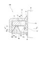
- FIG. 2 is an enlarged cross-sectional view around the seal member.
- FIG. 3 is an enlarged cross-sectional view of the seal member, showing a state before being assembled to the tube.
- FIG. 4 is an enlarged view of the IV part shown in FIG. 3 and shows a state before being assembled to the tube.
- FIG. 5 is a cross-sectional view taken along the line VV shown in FIG.
- shock absorber 100 as a reciprocating fluid pressure device according to an embodiment of the present invention will be described with reference to the accompanying drawings.
- FIG. 1 is a partial cross-sectional view of the shock absorber 100.
- the shock absorber 100 is provided, for example, between a vehicle body (not shown) and an axle, and generates a damping force to suppress vibration of the vehicle body.
- the shock absorber 100 includes a tube 10, a piston rod 20 that is movably inserted into the tube 10, and a piston 30 that is coupled to the piston rod 20.
- the piston rod 20 extends from the tube 10, the shock absorber 100 contracts when the piston rod 20 enters the tube 10, and the shock absorber 100 extends when the piston rod 20 retreats from the tube 10.
- a direction along the piston rod 20 is referred to as an “axial direction”, and a radial direction around the piston rod 20 is referred to as a “radial direction”.
- the piston 30 is slidably accommodated in the tube 10 and divides the inside of the tube 10 into a compression side chamber 11a and an extension side chamber 11b.
- the compression side chamber 11a and the extension side chamber 11b are filled with working oil as a working fluid.
- the piston 30 is formed with a pressure side passage 31a and an extension side passage 31b that communicate the pressure side chamber 11a and the extension side chamber 11b.
- the compression side passage 31a and the extension side passage 31b are opened and closed by a compression side damping valve 40a and an extension side damping valve 40b, respectively, as a damping force generator provided in the piston 30.
- the piston 30 moves in the direction of reducing the compression side chamber 11a and expanding the extension side chamber 11b.
- the pressure side damping valve 40a is opened by the pressure difference between the pressure side chamber 11a and the expansion side chamber 11b to open the pressure side passage 31a, and hydraulic fluid flows from the pressure side chamber 11a through the pressure side passage 31a into the expansion side chamber 11b.
- resistance is given to the flow of hydraulic fluid by the compression side damping valve 40a, and the shock absorber 100 exhibits a damping force.
- the piston 30 moves in a direction in which the expansion side chamber 11b is contracted and the compression side chamber 11a is expanded.
- the expansion side damping valve 40b is opened by the pressure difference between the expansion side chamber 11b and the compression side chamber 11a to open the expansion side passage 31b, and hydraulic oil flows from the expansion side chamber 11b into the compression side chamber 11a through the expansion side passage 31b.
- resistance is given to the flow of hydraulic oil by the expansion side damping valve 40b, and the shock absorber 100 exhibits a damping force.
- the compression side damping valve 40a and the extension side damping valve 40b impart a resistance to the flow of the hydraulic oil as the piston rod 20 moves to generate a damping force.
- the volume change in the tube 10 due to the movement of the piston rod 20 is compensated by the air chamber 12 formed by the free piston 50 in the tube 10.
- a rod guide 60 that supports the piston rod 20 via a bush 61 is provided on the inner periphery of the tube 10.
- the rod guide 60 is supported by a retaining ring 62 provided on the inner periphery of the tube 10.
- the open end 13 of the tube 10 is bent inward by caulking, and a seal member 70 that closes the space between the tube 10 and the piston rod 20 is provided between the open end 13 and the rod guide 60. . That is, the seal member 70 and the rod guide 60 are fixed to the tube 10 by being sandwiched between the open end 13 of the tube 10 and the retaining ring 62.
- the seal member 70 includes an annular base portion 71 through which the piston rod 20 is inserted, an oil lip portion 72 as an inner peripheral lip portion that extends in the axial direction from the inner periphery of the base portion 71, and a duct member.
- the strip part 73 and the outer periphery lip part 74 extended in the axial direction from the outer periphery of the base part 71 are provided.
- the base portion 71 is made of metal.
- the oil lip part 72, the dust lip part 73, and the outer peripheral lip part 74 are integrally formed of a rubber material as an elastic body.
- the oil lip portion 72 and the dust lip portion 73 are connected to each other via the connecting portion 75 extending in the axial direction between the inner peripheral surface of the base portion 71 and the outer peripheral surface of the piston 20.
- the outer peripheral lip portion 74 is connected to each other via a connecting portion 76 that extends in the radial direction between the base portion 71 and the rod guide 60.
- the oil lip part 72, the dust lip part 73, the outer peripheral lip part 74, the connecting part 75 and the connecting part 76 are bonded to the base part 71 by vulcanization bonding.
- the oil lip portion 72 is formed so as to protrude radially inward from the base portion 71 and in a direction in which the piston rod 20 enters the tube 10, and is in sliding contact with the outer periphery of the piston rod 20.
- the shock absorber 100 extends, the hydraulic oil adhering to the outer periphery of the piston rod 20 is scraped off by the oil lip portion 72 and remains in the tube 10. That is, the oil lip portion 72 prevents hydraulic oil from leaking from the tube 10.
- An annular groove 72a is formed on the outer periphery of the oil lip 72, and an annular garter spring 72b is attached to the groove 72a.
- the garter spring 72b ensures the tightening of the oil lip 72 to the piston rod 20.
- the dust lip 73 is formed so as to protrude radially inward from the base 71 and in a direction in which the piston rod 20 retracts from the tube 10, and is in sliding contact with the outer periphery of the piston rod 20.
- the shock absorber 100 contracts, the foreign matter adhering to the outer periphery of the piston rod 20 is scraped off by the dust lip 73. That is, the dust lip 73 prevents foreign matter from entering the tube 10.
- a garter spring may be attached to the outer periphery of the dust lip portion 73.
- the outer peripheral lip 74 extends annularly from the base 71 along the inner periphery of the tube 10 and is provided in a compressed state between the inner peripheral surface of the tube 10 and the outer peripheral surface of the rod guide 60.
- the rod guide 60 is provided with a protruding portion 60a that protrudes in the axial direction toward the seal member 70 at a distance from the inner peripheral surface of the tube 10, and the outer peripheral surface of the protruding portion 60 a and the tube 10.
- the outer peripheral lip 74 is provided in a compressed state between the inner peripheral surface and the inner peripheral surface. Therefore, the outer peripheral lip portion 74 is pressed against the inner peripheral surface of the tube 10 by the protrusion 60a, and leakage of hydraulic oil and entry of foreign matter between the outer peripheral lip portion 74 and the tube 10 can be prevented.
- the outer peripheral surface of the protruding portion 60 a includes an inclined portion 60 b that is inclined with respect to the inner peripheral surface of the tube 10. Therefore, when the shock absorber 100 is assembled, the outer peripheral lip 74 of the seal member 70 can be easily inserted between the outer peripheral surface of the protruding portion 60 a and the inner peripheral surface of the tube 10.
- the front end surface 60c of the projecting portion 60a is in contact with the connecting portion 76 of the seal member 70.
- the connecting portion 76 is formed with an abutting surface 76a that abuts on the distal end surface 60c of the protruding portion 60a.
- FIG. 3 is an enlarged cross-sectional view of the seal member 70, showing a state before being assembled to the tube 10, that is, a state where the outer peripheral lip 74 of the seal member 70 is not compressed by the tube 10 and the rod guide 60.
- the outer peripheral lip 74 swells outward in the radial direction when the tube 10 and the protruding portion 60 a of the rod guide 60 are not compressed (non-compressed state).
- the outer peripheral surface of the outer peripheral lip 74 has an outer pressing portion 74a that is pressed by the inner peripheral surface of the tube 10, and the outer pressing portion 74a has a maximum outer diameter in the non-compressed state. It bulges to become bigger than.
- the outer peripheral lip 74 is formed so that the outer peripheral surface is curved without being sharpened in an uncompressed state. Therefore, in a state where the seal member 70 is assembled to the tube 10, the local internal stress on the outer peripheral surface of the outer peripheral lip portion 74 can be reduced as compared with a case where the outer peripheral surface is sharp in an uncompressed state. The creep phenomenon on the outer periphery of the outer peripheral lip 74 can be reduced. Therefore, damage to the outer periphery of the outer peripheral lip 74 can be prevented. Thereby, the sealing performance of the sealing member 70 can be improved.
- the outer pressing portion 74 a of the outer peripheral lip portion 74 is provided away from the base portion 71 in the axial direction.
- the outer pressing portion 74a includes a first position 74b that is axially separated from the base portion 71, and a second position 74c that the outer peripheral surface of the outer peripheral lip portion 74 starts to move away from the inner peripheral surface of the tube 10.
- the outer side press part 74a swells and is formed in a curved shape over the whole. Therefore, the radius of curvature of the outer pressing portion 74a can be increased as compared with the case where only a part of the outer pressing portion 74a is curved. Therefore, the local internal stress on the outer peripheral surface of the outer peripheral lip portion 74 can be further reduced, and the creep phenomenon in the outer peripheral lip portion 74 can be further reduced. Thereby, the sealing performance of the seal member 70 can be further improved.
- the first position 74 b is a direction in which the piston rod 20 retreats from the tube 10 rather than a virtual extension surface 76 b obtained by extending the contact surface 76 a of the coupling portion 76 radially outward (see FIGS. 3 and 3). 4).
- the outer peripheral surface of the outer peripheral lip 74 is curved not only in the outer compression portion 74a but also between the first position 74b and the tip 74d of the outer peripheral lip 74 in an uncompressed state. Also good. In this case, the radius of curvature of the outer peripheral surface of the outer peripheral lip 74 can be increased. Therefore, the local internal stress on the outer peripheral surface of the outer peripheral lip portion 74 can be further reduced, and the creep phenomenon in the outer peripheral lip portion 74 can be further reduced. Thereby, the sealing performance of the seal member 70 can be further improved.
- the outer pressing portion 74a may be provided as a whole from the first position 74b located above the contact surface 76a of the connecting portion 76 to the tip 74d. That is, the outer peripheral lip 74 may be formed to be pressed by the inner peripheral surface of the tube 10 from the first position 74b to the tip 74d.
- An inner pressing portion 74 e that is pressed by the inclined portion 60 b of the rod guide 60 is provided on the inner peripheral surface of the outer peripheral lip portion 74.
- the inner pressing portion 74e includes a flat portion 74f along the axial direction and a curved portion 74g that curves from the flat portion 74f to the tip 74d in the non-compressed state. Therefore, in a state where the seal member 70 is assembled to the tube 10, local internal stress on the inner peripheral surface of the outer peripheral lip portion 74 is sharpened from the flat portion 74f to the tip 74d in the non-compressed state. Compared with the case where it exists, it can be made small and the creep phenomenon in the outer periphery lip
- the outer peripheral lip 74 has a radius of curvature of the outer pressing portion 74a larger than that of the curved portion 74g of the inner pressing portion 74e. Therefore, in a state where the seal member 70 is assembled to the tube 10, the local internal stress on the outer peripheral surface of the outer peripheral lip 74 is smaller than the local internal stress on the inner peripheral surface. Accordingly, the creep phenomenon on the outer periphery of the outer peripheral lip portion 74 can be further reduced, and damage to the outer periphery of the outer peripheral lip portion 74 can be prevented. Thereby, the sealing performance of the sealing member 70 can be improved.
- the pressing amount A of the outer peripheral lip portion 74 by the inner peripheral surface of the tube 10 is smaller than the pressing amount B of the outer peripheral lip portion 74 by the inclined portion 60 b of the rod guide 60.
- the pressing amount A of the outer peripheral lip portion 74 by the inner peripheral surface of the tube 10 is the outer peripheral surface of the inner peripheral surface of the tube 10 and the outer peripheral lip portion 74 in the direction orthogonal to the inner peripheral surface of the tube 10 in an uncompressed state.
- the pressing amount B of the outer peripheral lip portion 74 by the inclined portion 60b of the rod guide 60 is such that the inclined portion 60b and the inner peripheral surface of the outer peripheral lip portion 74 in the direction orthogonal to the inclined portion 60b of the rod guide 60 in the non-compressed state. Expressed as the maximum dimension B between.
- the pressing amounts A and B may be the bulging amounts of the outer pressing portion 74a and the inner pressing portion 74e of the outer peripheral lip portion 74 in the non-compressed state, respectively. That is, in the shock absorber 100, when the outer peripheral lip 74 is not compressed, the bulging amount of the outer pressing portion 74a is smaller than the bulging amount of the inner pressing portion 74e.
- the sealing member 70 the pressing amount A by the inner peripheral surface of the tube 10 is smaller than the pressing amount B by the inclined portion 60 b of the rod guide 60, and therefore the outer peripheral lip portion 74 of the outer peripheral lip portion 74 is in a state where the sealing member 70 is assembled to the tube 10.
- the internal stress near the outer peripheral surface is smaller than the internal stress near the inner peripheral surface. Accordingly, the creep phenomenon on the outer periphery of the outer peripheral lip portion 74 can be further reduced, and damage to the outer periphery of the outer peripheral lip portion 74 can be prevented. Thereby, the sealing performance of the sealing member 70 can be improved.
- the most pressed part in the inner pressing part 74e (the part pressed with the pressing amount B in FIG. 4) is the most pressed part in the outer pressing part 74a (the part pressed with the pressing amount A in FIG. 4). Rather, the piston rod 20 is arranged in a direction (downward in FIGS. 3 and 4) into the tube 10. Therefore, the pressing force by the inclined portion 60b of the rod guide 60 is likely to be applied by the outer pressing portion 74a. Therefore, the sealing performance of the seal member 70 can be further improved.
- the inner side press part 74e may be arrange
- the tube 10 is formed from a so-called electric sewing tube.
- the ERW pipe is manufactured by rolling a steel plate into a tubular shape, butting edges together and welding a seam. Since a weld bead that protrudes to the inside of the ERW pipe is formed in the welded portion, when the ERW pipe is used as the tube 10, the welded portion 10a (see FIG. 5) is cut from the inner side of the ERW pipe. Cut the weld bead.
- the electric resistance welded pipe is less expensive than a pipe member without a welded portion, as shown in FIG. 5, a recess 10b is formed inside the welded portion 10a as the weld bead is removed.
- the outer pressing portion 74a of the outer peripheral lip portion 74 is formed so as to swell in a curved shape as a whole, so that sufficient sealing performance is maintained even if an inexpensive electric sewing tube is used. can do.
- the volume of the outer peripheral lip 74 is smaller than the volume of the space 63 defined by the inner peripheral surface of the tube 10 and the outer peripheral surface of the rod guide 60. That is, the filling rate, which is the ratio of the volume of the outer peripheral lip 74 to the volume of the space 63, is less than 100%. Therefore, the escape area of the outer peripheral lip 74 is formed between the inner peripheral surface of the tube 10 and the outer peripheral surface of the rod guide 60. Therefore, the tube 10 can be prevented from expanding when the seal member 70 is assembled to the tube 10.
- the shock absorber 100 includes a tube 10, a piston rod 20 that is inserted into the tube 10 so as to be movable in the axial direction, a rod guide 60 that is provided on the inner periphery of the tube 10 and supports the piston rod 20, and a rod guide 60. And a seal member 70 that closes the space between the tube 10 and the piston rod 20.
- the seal member 70 is formed in an annular shape, and a base portion 71 through which the piston rod 20 is inserted, and an axial direction from the base portion 71.
- an outer peripheral lip portion 74 provided in a compressed state between the inner peripheral surface of the tube 10 and the outer peripheral surface of the rod guide 60, and the outer peripheral surface of the outer peripheral lip portion 74 is a base portion 71.
- the outer pressing portion 74a is provided in the axial direction and is pressed by the inner peripheral surface of the tube 10, and the outer pressing portion 74a has the outer peripheral lip portion 74 compressed. In a state where no is formed bulging in a curved shape throughout.
- the local internal stress on the outer peripheral surface of the outer peripheral lip 74 is smaller than when the outer peripheral surface is sharp in an uncompressed state. Therefore, damage to the outer peripheral lip 74 can be prevented. Further, it is possible to prevent the outer peripheral lip 74 from being sandwiched between the tube 10 and the base 71 in an excessively stressed state. Therefore, the creep phenomenon of the outer peripheral lip 74 can be suppressed. Thereby, the sealing performance of the sealing member 70 in the shock absorber 100 can be improved.
- the outer peripheral surface of the rod guide 60 has an inclined portion 60b inclined with respect to the inner peripheral surface of the tube 10, and the inner peripheral surface of the outer peripheral lip portion 74 is pressed by the inclined portion 60b.
- the inner pressing portion 74e is curved in a state where the outer peripheral lip portion 74 is not compressed, and the outer peripheral lip portion 74 has a pressing amount A by the inner peripheral surface of the tube 10 that is a rod. It is smaller than the pressing amount B by the inclined portion 60 b of the guide 60.
- the local internal stress on the outer peripheral surface of the outer peripheral lip 74 is smaller than the local internal stress on the inner peripheral surface of the outer peripheral lip 74. Therefore, it is possible to prevent the vicinity of the outer peripheral surface of the outer peripheral lip 74 from being damaged, and the sealing performance of the seal member 70 in the shock absorber 100 can be further improved.
- the pressing amount A of the outer peripheral lip portion 74 by the inner peripheral surface of the tube 10 is such that the inner peripheral surface and the outer peripheral lip portion of the tube 10 in the direction orthogonal to the inner peripheral surface of the tube 10 in an uncompressed state.
- 74 is the maximum dimension between the outer peripheral surface of the rod guide 60 and the pressing amount B of the outer peripheral lip portion 74 by the inclined portion 60b of the rod guide 60 is an inclined portion in a direction orthogonal to the inclined portion 60b of the rod guide 60 in the non-compressed state. This is the maximum dimension between 60b and the inner peripheral surface of the outer peripheral lip 74.
- the local internal stress on the outer peripheral surface of the outer peripheral lip 74 is smaller than the local internal stress on the inner peripheral surface of the outer peripheral lip 74. Therefore, it is possible to prevent the vicinity of the outer peripheral surface of the outer peripheral lip 74 from being damaged, and the sealing performance of the seal member 70 in the shock absorber 100 can be further improved.
- the tube 10 is formed from an electric resistance welded tube having a welded portion 10a at the joint, and the electric resistance welded tube has a recessed portion 10b inside the welded portion 10a.
- the volume of the outer peripheral lip 74 is smaller than the volume of the space 63 defined by the inner peripheral surface of the tube 10 and the outer peripheral surface of the rod guide 60.
- the escape area of the outer peripheral lip 74 is formed between the inner peripheral surface of the tube 10 and the outer peripheral surface of the rod guide 60. Therefore, the tube 10 can be prevented from expanding.
- the working oil is used as the working fluid, but an incompressible fluid such as water or an aqueous solution may be used instead of the working oil.
- the single cylinder type shock absorber in which the compression side chamber 11a, the expansion side chamber 11b, and the air chamber 12 are formed in the tube 10 is described as the shock absorber 100.
- the shock absorber 100 is formed on the outer periphery of the inner tube. It may be a multi-cylinder shock absorber in which a tube is provided and a reservoir is formed between the inner tube and the outer tube.
- the shock absorber 100 has been described.
- the present invention is also applicable to a reciprocating fluid pressure device such as a fluid pressure cylinder.
Landscapes
- Engineering & Computer Science (AREA)
- General Engineering & Computer Science (AREA)
- Mechanical Engineering (AREA)
- Fluid-Damping Devices (AREA)
- Sealing With Elastic Sealing Lips (AREA)
Abstract
緩衝器(100)は、チューブ(10)と、ピストンロッド(20)と、ロッドガイド(60)と、チューブ(10)とピストンロッド(20)との間を閉塞するシール部材(70)と、を備え、シール部材(70)は、ベース部(71)と、ベース部(71)から軸方向に延在しチューブ(10)の内周面とロッドガイド(60)の外周面との間に圧縮された状態で設けられる外周リップ部(74)と、を有し、外周リップ部(74)の外周面は、ベース部(71)から軸方向に離れて設けられチューブ(10)の内周面により押圧される外側押圧部(74a)を有し、外側押圧部(74a)は、外周リップ部(74)が圧縮されていない状態において、全体に渡って湾曲状に膨らんで形成される。
Description
本発明は、往復動型流体圧機器に関する。
緩衝器や流体圧シリンダ等の往復動型流体圧機器において、チューブとピストンロッドとの間を閉塞する環状のシール部材が知られている(JP2007-155078A及びJP2001-173797A)。JP2007-155078A及びJP2001-173797Aに開示される緩衝器では、シール部材は、チューブの内周に固定されるロッドガイドに支持される金属環と、金属環に加硫接着された外周リップ部と、を有する。外周リップ部は、チューブの内周面とロッドガイドの外周面との間に圧縮状態で設けられており、これにより、チューブを密封している。
JP2007-155078Aに開示される緩衝器では、シール部材の外周リップ部は、圧縮されていない状態において径方向外側に尖って膨らむように形成されている。そのため、緩衝器が組み立てられ外周リップ部がチューブとロッドガイドとにより圧縮された状態では、外周リップ部に局所的な内部応力が生じ、外周リップ部の一部が破損してシール部材の密封性が低下するおそれがある。
JP2001-173797Aに開示される緩衝器では、シール部材の外周リップ部は、金属環の外周から先端に向けて湾曲する外周を有している。そのため、チューブをかしめてシール部材をチューブに固定する際に、外周リップ部のうち金属環の外周に結合する部分は、金属からなるチューブと金属環との間に挟まれ過度な応力を受ける。それにより、外周リップ部のクリープ現象が促進されて密封性が早期に低下し、油漏れするおそれがある。
本発明は、緩衝器におけるシール部材の密封性を向上させることを目的とする。
本発明のある態様によれば、往復動型流体圧機器は、チューブと、チューブ内に軸方向に移動自在に挿入されるピストンロッドと、チューブの内周に設けられ、ピストンロッドを支持するロッドガイドと、ロッドガイドに支持され、チューブとピストンロッドとの間を閉塞するシール部材と、を備え、シール部材は、環状に形成されピストンロッドが挿通するベース部と、ベース部から軸方向に延在しチューブの内周面とロッドガイドの外周面との間に圧縮された状態で設けられる外周リップ部と、を有し、外周リップ部の外周面は、ベース部から軸方向に離れて設けられチューブの内周面により押圧される外側押圧部を有し、外側押圧部は、外周リップ部が圧縮されていない状態において、全体に渡って湾曲状に膨らんで形成される。
以下、添付図面を参照しながら本発明の実施形態に係る往復動型流体圧機器としての緩衝器100について説明する。
図1は、緩衝器100の部分断面図である。緩衝器100は、例えば、車両(図示せず)の車体と車軸との間に設けられ、減衰力を発生させて車体の振動を抑制する。
緩衝器100は、チューブ10と、チューブ10に移動自在に挿入されるピストンロッド20と、ピストンロッド20に連結されるピストン30と、を備える。ピストンロッド20は、チューブ10から延出しており、ピストンロッド20がチューブ10内に進入することにより緩衝器100は収縮し、ピストンロッド20がチューブ10から退出することにより緩衝器100は伸長する。
以下において、ピストンロッド20に沿う方向を「軸方向」と称し、ピストンロッド20を中心とする放射方向を「径方向」と称する。
ピストン30は、チューブ10に摺動自在に収容され、チューブ10内を圧側室11aと伸側室11bとに区画する。圧側室11a及び伸側室11bには、作動流体としての作動油が封入される。ピストン30には、圧側室11aと伸側室11bとを連通する圧側通路31a及び伸側通路31bが形成される。圧側通路31a及び伸側通路31bは、それぞれ、ピストン30に設けられる減衰力発生部としての圧側減衰バルブ40a及び伸側減衰バルブ40bにより開閉される。
緩衝器100が収縮する際には、ピストン30は、圧側室11aを縮小し伸側室11bを拡大する方向に移動する。圧側室11aと伸側室11bとの差圧により圧側減衰バルブ40aは開弁して圧側通路31aを開放し、圧側室11aから作動油が圧側通路31aを通じて伸側室11bに流入する。このとき、作動油の流れに圧側減衰バルブ40aにより抵抗が付与され、緩衝器100は減衰力を発揮する。
緩衝器100が伸長する際には、ピストン30は、伸側室11bを縮小し圧側室11aを拡大する方向に移動する。伸側室11bと圧側室11aとの差圧により伸側減衰バルブ40bは開弁して伸側通路31bを開放し、伸側室11bから作動油が伸側通路31bを通じて圧側室11aに流入する。このとき、作動油の流れに伸側減衰バルブ40bにより抵抗が付与され、緩衝器100は減衰力を発揮する。
このように、圧側減衰バルブ40a及び伸側減衰バルブ40bは、ピストンロッド20の移動に伴って作動油の流れに抵抗を付与して減衰力を発生する。
ピストンロッド20の移動に伴うチューブ10内の容積変化は、チューブ10内にフリーピストン50により形成される気室12によって補償される。
チューブ10の内周には、ブッシュ61を介してピストンロッド20を支持するロッドガイド60が設けられる。ロッドガイド60は、チューブ10の内周に設けられた止め輪62に支持される。
チューブ10の開口端13は、かしめ加工により内側に折り曲げられており、開口端13とロッドガイド60との間に、チューブ10とピストンロッド20との間を閉塞するシール部材70が設けられている。つまり、シール部材70及びロッドガイド60は、チューブ10の開口端13と止め輪62とにより挟持されてチューブ10に固定される。
図2に示すように、シール部材70は、ピストンロッド20が挿通する環状のベース部71と、ベース部71の内周から軸方向に延在する内周リップ部としてのオイルリップ部72及びダストリップ部73と、ベース部71の外周から軸方向に延在する外周リップ部74と、を備える。ベース部71は金属からなる。オイルリップ部72、ダストリップ部73及び外周リップ部74は、弾性体としてのゴム材で一体的に形成されている。すなわち、オイルリップ部72とダストリップ部73とは、ベース部71の内周面とピストン20の外周面との間を軸方向に延びる連結部75を介して互いに連結され、オイルリップ部72と外周リップ部74とは、ベース部71とロッドガイド60との間を径方向に延びる連結部76を介して互いに連結されている。オイルリップ部72、ダストリップ部73、外周リップ部74、連結部75及び連結部76は、加硫接着によりベース部71に接着される。
オイルリップ部72は、ベース部71から径方向内側かつピストンロッド20がチューブ10に進入する方向に突出するように形成され、ピストンロッド20の外周に摺接する。緩衝器100が伸長する際には、ピストンロッド20の外周に付着する作動油はオイルリップ部72により掻き落され、チューブ10内に残る。つまり、オイルリップ部72は、チューブ10から作動油が漏出するのを防止する。
オイルリップ部72の外周には、環状の溝部72aが形成され、溝部72aに環状のガータースプリング72bが装着されている。ガータースプリング72bによって、オイルリップ部72におけるピストンロッド20に対する締め付けが保障される。
ダストリップ部73は、ベース部71から径方向内側かつピストンロッド20がチューブ10から退出する方向に突出するように形成され、ピストンロッド20の外周に摺接する。緩衝器100が収縮する際には、ピストンロッド20の外周に付着する異物はダストリップ部73により掻き落される。つまり、ダストリップ部73は、チューブ10に異物が進入するのを防止する。なお、オイルリップ部72と同様に、ダストリップ部73の外周にガータースプリングが装着されていてもよい。
外周リップ部74は、ベース部71からチューブ10の内周に沿って環状に延在し、チューブ10の内周面とロッドガイド60の外周面との間に圧縮された状態で設けられる。具体的には、ロッドガイド60には、シール部材70に向かって軸方向に突出する突出部60aがチューブ10の内周面と間隔を開けて設けられ、突出部60aの外周面とチューブ10の内周面との間に外周リップ部74が圧縮された状態で設けられる。そのため、外周リップ部74が突出部60aによりチューブ10の内周面に押し付けられ、外周リップ部74とチューブ10の間における作動油の漏出及び異物の進入を防止することができる。
突出部60aの外周面は、チューブ10の内周面に対して傾斜した傾斜部60bを含む。そのため、緩衝器100の組立時において、シール部材70の外周リップ部74を突出部60aの外周面とチューブ10の内周面との間に容易に挿入することができる。
また、突出部60aの先端面60cは、シール部材70の連結部76と当接している。換言すれば、連結部76には、突出部60aの先端面60cと当接する当接面76aが形成される。
図3は、シール部材70の拡大断面図であり、チューブ10に組み付ける前の状態、すなわちシール部材70の外周リップ部74がチューブ10とロッドガイド60とにより圧縮されていない状態を示す。なお、図3では、チューブ10、ピストンロッド20及びロッドガイド60の断面を2点鎖線で示している。
図3及び図4に示すように、外周リップ部74は、チューブ10とロッドガイド60の突出部60aとにより圧縮されていない状態(非圧縮状態)では、径方向外側に膨らんでいる。具体的には、外周リップ部74の外周面は、チューブ10の内周面により押圧される外側押圧部74aを有し、外側押圧部74aは、非圧縮状態において最大外径がチューブ10の内径よりも大きくなるように膨らんでいる。
外周リップ部74は、非圧縮状態において、外周面が尖ることなく湾曲するように形成されている。そのため、シール部材70がチューブ10に組み付けられた状態において、外周リップ部74の外周面での局所的な内部応力を、非圧縮状態で外周面が尖っている場合と比較して小さくすることができ、外周リップ部74の外周におけるクリープ現象を軽減することができる。したがって、外周リップ部74の外周の破損を防止することができる。これにより、シール部材70の密封性を向上させることができる。
外周リップ部74の外側押圧部74aは、ベース部71から軸方向に離れて設けられる。具体的には、外側押圧部74aは、ベース部71から軸方向に離れた第1位置74bと、外周リップ部74の外周面がチューブ10の内周面から離れ始める第2位置74cと、の間に設けられる。そして、外周リップ部74が圧縮されていない状態において、外側押圧部74aは、全体に渡って湾曲状に膨らんで形成される。そのため、外側押圧部74aの曲率半径を、外側押圧部74aの一部のみが湾曲している場合と比較して大きくすることができる。したがって、外周リップ部74の外周面での局所的な内部応力をより小さくすることができ、外周リップ部74におけるクリープ現象をより軽減することができる。これにより、シール部材70の密封性をより向上させることができる。
図4に示すように、第1位置74bは、連結部76の当接面76aを径方向外側に延長した仮想延長面76bよりも、ピストンロッド20がチューブ10から退出する方向(図3及び図4における上方)に位置している。
なお、外周リップ部74の外周面は、非圧縮状態において、外側押圧部74aだけでなく、第1位置74bと、外周リップ部74の先端74dと、の間の全体に渡って湾曲していてもよい。この場合には、外周リップ部74の外周面の曲率半径をより大きくすることができる。したがって、外周リップ部74の外周面での局所的な内部応力をより小さくすることができ、外周リップ部74におけるクリープ現象をより軽減することができる。これにより、シール部材70の密封性をより向上させることができる。
また、外側押圧部74aは、連結部76の当接面76aより上方に位置する第1位置74bから先端74dに渡って全体的に設けられていてもよい。すなわち、外周リップ部74は、第1位置74bから先端74dに渡ってチューブ10の内周面により押圧されるように形成されていてもよい。
外周リップ部74の内周面には、ロッドガイド60の傾斜部60bにより押圧される内側押圧部74eが設けられる。内側押圧部74eは、非圧縮状態において、軸方向に沿う平面部74fと、平面部74fから先端74dにかけて湾曲する湾曲部74gと、を含む。そのため、シール部材70がチューブ10に組み付けられた状態において、外周リップ部74の内周面での局所的な内部応力を、非圧縮状態で外周リップ部74が平面部74fから先端74dにかけて尖っている場合と比較して小さくすることができ、外周リップ部74におけるクリープ現象を軽減することができる。これにより、突出部60aによりチューブ10に向けて外周リップ部74に加えられる押し付け力が弱まるのを防止することができ、シール部材70の密封性を向上させることができる。
外周リップ部74は、非圧縮状態において、外側押圧部74aの曲率半径が、内側押圧部74eの湾曲部74gの曲率半径よりも大きい。そのため、シール部材70がチューブ10に組み付けられた状態において、外周リップ部74の外周面での局所的な内部応力は、内周面での局所的な内部応力よりも小さくなる。したがって、外周リップ部74の外周におけるクリープ現象をより軽減することができ、外周リップ部74の外周の破損を防止することができる。これにより、シール部材70の密封性を向上させることができる。
チューブ10の内周面による外周リップ部74の押圧量Aは、ロッドガイド60の傾斜部60bによる外周リップ部74の押圧量Bよりも小さい。ここで、チューブ10の内周面による外周リップ部74の押圧量Aは、非圧縮状態において、チューブ10の内周面に直交する方向におけるチューブ10の内周面と外周リップ部74の外周面との間の最大寸法Aとして表される。また、ロッドガイド60の傾斜部60bによる外周リップ部74の押圧量Bは、非圧縮状態において、ロッドガイド60の傾斜部60bに直交する方向における傾斜部60bと外周リップ部74の内周面との間の最大寸法Bとして表される。
なお、押圧量A,Bは、それぞれ、非圧縮状態における外周リップ部74の外側押圧部74a及び内側押圧部74eの膨らみ量であってもよい。すなわち、緩衝器100では、外周リップ部74が圧縮されていない状態において、外側押圧部74aの膨らみ量が、内側押圧部74eの膨らみ量よりも小さい。
シール部材70では、チューブ10の内周面による押圧量Aがロッドガイド60の傾斜部60bによる押圧量Bよりも小さいので、シール部材70がチューブ10に組み付けられた状態において、外周リップ部74の外周面近傍での内部応力は、内周面近傍での内部応力よりも小さくなる。したがって、外周リップ部74の外周におけるクリープ現象をより軽減することができ、外周リップ部74の外周の破損を防止することができる。これにより、シール部材70の密封性を向上させることができる。
内側押圧部74eにおける最も押圧される部位(図4において、押圧量Bで押圧される部位)は、外側押圧部74aにおける最も押圧される部位(図4において、押圧量Aで押圧される部位)よりも、ピストンロッド20がチューブ10に進入する方向(図3及び図4における下方)に配置される。そのため、ロッドガイド60の傾斜部60bによる押圧力が外側押圧部74aによりかかりやすくなる。したがって、シール部材70の密封性をより向上させることができる。
なお、内側押圧部74eは、外側押圧部74aの一部よりも図3及び図4における下方に配置されていてもよいし、外側押圧部74aの全部よりも図3及び図4における下方に配置されていてもよい。すなわち、内側押圧部74eは、外側押圧部74aの少なくとも一部よりも図3及び図4にける下方に配置されていていればよい。この場合においても、ロッドガイド60の傾斜部60bによる押圧力が外側押圧部74aにかかりやすくなり、シール部材70の密封性を向上させることができる。
チューブ10は、いわゆる電縫管から形成される。電縫管は、鋼板を管状に丸めて縁どうしを突き合わせ、継ぎ目を溶接することにより造られる。溶接部には、電縫管の内側に突出する溶接ビードが形成されるため、電縫管をチューブ10として用いる場合には、溶接部10a(図5参照)を電縫管の内側から切削して溶接ビードを切除する。
電縫管は、溶接部のない管部材と比較して安価であるものの、図5に示すように、溶接ビードの切除に伴い、溶接部10aの内側に窪み部10bが形成される。
仮に、径方向に尖って膨らむ外周リップを有する関連するシール部材を用いてチューブ10とピストンロッド20との間を閉塞すると、窪み部10bに密着する面積が十分にとれず、作動油がチューブ10から漏れるおそれがある。
シール部材70では、図3に示すように、外周リップ部74の外側押圧部74aが全体にわたって湾曲状に膨らんで形成されているため、安価な電縫管を用いても十分な密封性を維持することができる。
また、緩衝器100では、外周リップ部74の体積は、チューブ10の内周面とロッドガイド60の外周面とにより画定される空間63の体積よりも小さい。つまり、当該空間63の体積に対する外周リップ部74の体積の比である充填率は、100%未満である。そのため、外周リップ部74の逃げ場がチューブ10の内周面とロッドガイド60の外周面との間に形成される。したがって、シール部材70をチューブ10に組み付ける際にチューブ10が膨らむのを防止することができる。
以下、本発明の実施形態の構成、作用、及び効果をまとめて説明する。
緩衝器100は、チューブ10と、チューブ10内に軸方向に移動自在に挿入されるピストンロッド20と、チューブ10の内周に設けられ、ピストンロッド20を支持するロッドガイド60と、ロッドガイド60に支持され、チューブ10とピストンロッド20との間を閉塞するシール部材70と、を備え、シール部材70は、環状に形成されピストンロッド20が挿通するベース部71と、ベース部71から軸方向に延在しチューブ10の内周面とロッドガイド60の外周面との間に圧縮された状態で設けられる外周リップ部74と、を有し、外周リップ部74の外周面は、ベース部71から軸方向に離れて設けられチューブ10の内周面により押圧される外側押圧部74aを有し、外側押圧部74aは、外周リップ部74が圧縮されていない状態において、全体に渡って湾曲状に膨らんで形成される。
この構成では、外周リップ部74の外周面での局所的な内部応力は、非圧縮状態で外周面が尖っている場合と比較して小さい。したがって、外周リップ部74の破損を防止することができる。また、外周リップ部74がチューブ10とベース部71との間で過度な応力を受けた状態で挟まれるのを防ぐことができる。したがって、外周リップ部74のクリープ現象を抑制することができる。これにより、緩衝器100におけるシール部材70の密封性を向上させることができる。
また、緩衝器100では、ロッドガイド60の外周面が、チューブ10の内周面に対して傾斜した傾斜部60bを有し、外周リップ部74の内周面は、傾斜部60bにより押圧される内側押圧部74eを有し、内側押圧部74eは、外周リップ部74が圧縮されていない状態において、湾曲しており、外周リップ部74は、チューブ10の内周面による押圧量Aが、ロッドガイド60の傾斜部60bによる押圧量Bよりも小さい。
この構成では、外周リップ部74の外周面での局所的な内部応力は、外周リップ部74の内周面での局所的な内部応力と比較して小さい。したがって、外周リップ部74の外周面近傍部の破損を防止することができ、緩衝器100におけるシール部材70の密封性をより向上させることができる。
また、緩衝器100では、チューブ10の内周面による外周リップ部74の押圧量Aは、非圧縮状態において、チューブ10の内周面に直交する方向におけるチューブ10の内周面と外周リップ部74の外周面との間の最大寸法であり、ロッドガイド60の傾斜部60bによる外周リップ部74の押圧量Bは、非圧縮状態において、ロッドガイド60の傾斜部60bに直交する方向における傾斜部60bと外周リップ部74の内周面との間の最大寸法である。
この構成では、外周リップ部74の外周面での局所的な内部応力は、外周リップ部74の内周面での局所的な内部応力と比較して小さい。したがって、外周リップ部74の外周面近傍部の破損を防止することができ、緩衝器100におけるシール部材70の密封性をより向上させることができる。
また、緩衝器100では、チューブ10は、継ぎ目に溶接部10aを有する電縫管から形成され、電縫管は、溶接部10aの内側に窪み部10bを有する。
この構成では、安価な電縫管を用いても十分な密封性を維持することができる。
また、緩衝器100では、外周リップ部74の体積は、チューブ10の内周面とロッドガイド60の外周面とにより画定される空間63の体積よりも小さい。
この構成では、外周リップ部74の逃げ場がチューブ10の内周面とロッドガイド60の外周面との間に形成される。したがって、チューブ10が膨らむのを防止することができる。
以上、本発明の実施形態について説明したが、上記実施形態は本発明の適用例の一部を示したに過ぎず、本発明の技術的範囲を上記実施形態の具体的構成に限定する趣旨ではない。
上記実施形態では、作動流体として、作動油を使用しているが、作動油の代わりに水や水溶液等の非圧縮性流体を使用してもよい。
上記実施形態では、緩衝器100として、チューブ10内に圧側室11a、伸側室11b及び気室12が形成される単筒型緩衝器について説明したが、緩衝器100は、インナーチューブの外周にアウターチューブが設けられインナーチューブとアウターチューブの間にリザーバが形成される複筒型緩衝器であってもよい。
また、上記実施形態では、緩衝器100について説明したが、本発明は、流体圧シリンダ等の往復動型流体圧機器にも適用可能である。
本願は2018年3月26日に日本国特許庁に出願された特願2018-058027に基づく優先権を主張し、この出願の全ての内容は参照により本明細書に組み込まれる。
Claims (5)
- チューブと、
前記チューブ内に軸方向に移動自在に挿入されるピストンロッドと、
前記チューブの内周に設けられ、前記ピストンロッドを支持するロッドガイドと、
前記ロッドガイドに支持され、前記チューブと前記ピストンロッドとの間を閉塞するシール部材と、を備え、
前記シール部材は、
環状に形成され前記ピストンロッドが挿通するベース部と、
前記ベース部から前記軸方向に延在し前記チューブの内周面と前記ロッドガイドの外周面との間に圧縮された状態で設けられる外周リップ部と、を有し、
前記外周リップ部の外周面は、前記ベース部から前記軸方向に離れて設けられ前記チューブの内周面により押圧される外側押圧部を有し、
前記外側押圧部は、前記外周リップ部が圧縮されていない状態において、全体に渡って湾曲状に膨らんで形成される
往復動型流体圧機器。 - 請求項1に記載の往復動型流体圧機器であって、
前記ロッドガイドの外周面は、前記チューブの内周面に対して傾斜した傾斜部を有し、
前記外周リップ部の内周面は、前記傾斜部により押圧される内側押圧部を有し、
前記内側押圧部は、前記外周リップ部が圧縮されていない状態において、湾曲しており、
前記外周リップ部は、前記チューブの内周面による押圧量が、前記ロッドガイドの前記傾斜部による押圧量よりも小さい
往復動型流体圧機器。 - 請求項2に記載の往復動型流体圧機器であって、
前記チューブの内周面による前記外周リップ部の押圧量は、非圧縮状態において、前記チューブの内周面に直交する方向における前記チューブの内周面と前記外周リップ部の外周面との間の最大寸法であり、
前記ロッドガイドの前記傾斜部による前記外周リップ部の押圧量は、非圧縮状態において、前記ロッドガイドの前記傾斜部に直交する方向における前記傾斜部と前記外周リップ部の内周面との間の最大寸法である
往復動型流体圧機器。 - 請求項1に記載の往復動型流体圧機器であって、
前記チューブは、継ぎ目に溶接部を有する電縫管から形成され、
前記電縫管は、前記溶接部の内側に窪み部を有する
往復動型流体圧機器。 - 請求項1に記載の往復動型流体圧機器であって、
前記外周リップ部の体積は、前記チューブの内周面と前記ロッドガイドの外周面とにより画定される空間の体積よりも小さい
往復動型流体圧機器。
Priority Applications (2)
| Application Number | Priority Date | Filing Date | Title |
|---|---|---|---|
| CN201980014960.4A CN111757996B (zh) | 2018-03-26 | 2019-03-26 | 往复式流体压设备 |
| JP2020510948A JP7222979B2 (ja) | 2018-03-26 | 2019-03-26 | 往復動型流体圧機器 |
Applications Claiming Priority (2)
| Application Number | Priority Date | Filing Date | Title |
|---|---|---|---|
| JP2018-058027 | 2018-03-26 | ||
| JP2018058027 | 2018-03-26 |
Publications (1)
| Publication Number | Publication Date |
|---|---|
| WO2019189236A1 true WO2019189236A1 (ja) | 2019-10-03 |
Family
ID=68062110
Family Applications (1)
| Application Number | Title | Priority Date | Filing Date |
|---|---|---|---|
| PCT/JP2019/012962 Ceased WO2019189236A1 (ja) | 2018-03-26 | 2019-03-26 | 往復動型流体圧機器 |
Country Status (3)
| Country | Link |
|---|---|
| JP (1) | JP7222979B2 (ja) |
| CN (1) | CN111757996B (ja) |
| WO (1) | WO2019189236A1 (ja) |
Citations (4)
| Publication number | Priority date | Publication date | Assignee | Title |
|---|---|---|---|---|
| JPH11132338A (ja) * | 1997-10-28 | 1999-05-21 | Nok Corp | 密封装置 |
| JP2005016721A (ja) * | 2003-05-30 | 2005-01-20 | Tokico Ltd | 単筒式緩衝器 |
| JP2007107550A (ja) * | 2005-10-11 | 2007-04-26 | Nok Corp | 往復動軸用密封装置 |
| JP2010281373A (ja) * | 2009-06-04 | 2010-12-16 | Nok Corp | アブソーバ用シール |
Family Cites Families (4)
| Publication number | Priority date | Publication date | Assignee | Title |
|---|---|---|---|---|
| JP6335019B2 (ja) * | 2014-05-19 | 2018-05-30 | Kyb株式会社 | 緩衝器 |
| JP6355067B2 (ja) * | 2014-06-11 | 2018-07-11 | Nok株式会社 | シール装置 |
| JP3192593U (ja) * | 2014-06-11 | 2014-08-21 | Nok株式会社 | シール装置 |
| CN105042077A (zh) * | 2015-07-07 | 2015-11-11 | 青岛睿辰密封科技有限公司 | 一种高性能多用途齿状y形组合密封装置 |
-
2019
- 2019-03-26 WO PCT/JP2019/012962 patent/WO2019189236A1/ja not_active Ceased
- 2019-03-26 JP JP2020510948A patent/JP7222979B2/ja active Active
- 2019-03-26 CN CN201980014960.4A patent/CN111757996B/zh active Active
Patent Citations (4)
| Publication number | Priority date | Publication date | Assignee | Title |
|---|---|---|---|---|
| JPH11132338A (ja) * | 1997-10-28 | 1999-05-21 | Nok Corp | 密封装置 |
| JP2005016721A (ja) * | 2003-05-30 | 2005-01-20 | Tokico Ltd | 単筒式緩衝器 |
| JP2007107550A (ja) * | 2005-10-11 | 2007-04-26 | Nok Corp | 往復動軸用密封装置 |
| JP2010281373A (ja) * | 2009-06-04 | 2010-12-16 | Nok Corp | アブソーバ用シール |
Also Published As
| Publication number | Publication date |
|---|---|
| JPWO2019189236A1 (ja) | 2021-03-25 |
| CN111757996B (zh) | 2023-02-28 |
| JP7222979B2 (ja) | 2023-02-15 |
| CN111757996A (zh) | 2020-10-09 |
Similar Documents
| Publication | Publication Date | Title |
|---|---|---|
| JP5756392B2 (ja) | 密封装置及びこの密封装置を備える緩衝器 | |
| WO2015083593A1 (ja) | シール装置 | |
| CN106233026B (zh) | 缓冲器 | |
| JP2002070912A (ja) | 油圧緩衝器のチューブ構造及びチューブ製造方法 | |
| US20180087665A1 (en) | Metal bellows type accumulator | |
| JP7002376B2 (ja) | ショックアブソーバ | |
| KR101983482B1 (ko) | 완충기 | |
| JP5131594B2 (ja) | エアサスペンション装置 | |
| JP6771522B2 (ja) | 緩衝器 | |
| KR102138416B1 (ko) | 실린더 장치 | |
| US20090140496A1 (en) | Sealing Device | |
| WO2019189236A1 (ja) | 往復動型流体圧機器 | |
| JP6810603B2 (ja) | シリンダ装置 | |
| JP2004251413A (ja) | 往復動軸用密封装置 | |
| CN110662906B (zh) | 缓冲器 | |
| JP6754385B2 (ja) | シール部材、及び緩衝器 | |
| JP6443985B2 (ja) | シリンダ装置 | |
| WO2025070131A9 (ja) | シール部材及び緩衝器 | |
| JP6616672B2 (ja) | バンプストッパ、及び緩衝器 | |
| JP5330288B2 (ja) | エアバネ付緩衝器 | |
| JP2016188650A (ja) | シリンダ装置 | |
| US12345310B2 (en) | Sealing device | |
| CN100398866C (zh) | 单缸液压减振器 | |
| JP5879206B2 (ja) | シリンダ装置 | |
| JP2020112260A (ja) | 緩衝器 |
Legal Events
| Date | Code | Title | Description |
|---|---|---|---|
| 121 | Ep: the epo has been informed by wipo that ep was designated in this application |
Ref document number: 19774652 Country of ref document: EP Kind code of ref document: A1 |
|
| ENP | Entry into the national phase |
Ref document number: 2020510948 Country of ref document: JP Kind code of ref document: A |
|
| NENP | Non-entry into the national phase |
Ref country code: DE |
|
| 122 | Ep: pct application non-entry in european phase |
Ref document number: 19774652 Country of ref document: EP Kind code of ref document: A1 |