WO2019188080A1 - ワイヤーハーネス及びワイヤーハーネスの製造方法 - Google Patents
ワイヤーハーネス及びワイヤーハーネスの製造方法 Download PDFInfo
- Publication number
- WO2019188080A1 WO2019188080A1 PCT/JP2019/009000 JP2019009000W WO2019188080A1 WO 2019188080 A1 WO2019188080 A1 WO 2019188080A1 JP 2019009000 W JP2019009000 W JP 2019009000W WO 2019188080 A1 WO2019188080 A1 WO 2019188080A1
- Authority
- WO
- WIPO (PCT)
- Prior art keywords
- electric wire
- sheet material
- wire
- insulating coating
- layer
- Prior art date
- Legal status (The legal status is an assumption and is not a legal conclusion. Google has not performed a legal analysis and makes no representation as to the accuracy of the status listed.)
- Ceased
Links
Images


Classifications
-
- H—ELECTRICITY
- H01—ELECTRIC ELEMENTS
- H01B—CABLES; CONDUCTORS; INSULATORS; SELECTION OF MATERIALS FOR THEIR CONDUCTIVE, INSULATING OR DIELECTRIC PROPERTIES
- H01B13/00—Apparatus or processes specially adapted for manufacturing conductors or cables
- H01B13/0013—Apparatus or processes specially adapted for manufacturing conductors or cables for embedding wires in plastic layers
-
- B—PERFORMING OPERATIONS; TRANSPORTING
- B60—VEHICLES IN GENERAL
- B60R—VEHICLES, VEHICLE FITTINGS, OR VEHICLE PARTS, NOT OTHERWISE PROVIDED FOR
- B60R16/00—Electric or fluid circuits specially adapted for vehicles and not otherwise provided for; Arrangement of elements of electric or fluid circuits specially adapted for vehicles and not otherwise provided for
- B60R16/02—Electric or fluid circuits specially adapted for vehicles and not otherwise provided for; Arrangement of elements of electric or fluid circuits specially adapted for vehicles and not otherwise provided for electric constitutive elements
- B60R16/0207—Wire harnesses
-
- H—ELECTRICITY
- H01—ELECTRIC ELEMENTS
- H01B—CABLES; CONDUCTORS; INSULATORS; SELECTION OF MATERIALS FOR THEIR CONDUCTIVE, INSULATING OR DIELECTRIC PROPERTIES
- H01B13/00—Apparatus or processes specially adapted for manufacturing conductors or cables
- H01B13/012—Apparatus or processes specially adapted for manufacturing conductors or cables for manufacturing wire harnesses
- H01B13/01209—Details
-
- H—ELECTRICITY
- H01—ELECTRIC ELEMENTS
- H01B—CABLES; CONDUCTORS; INSULATORS; SELECTION OF MATERIALS FOR THEIR CONDUCTIVE, INSULATING OR DIELECTRIC PROPERTIES
- H01B7/00—Insulated conductors or cables characterised by their form
- H01B7/0045—Cable-harnesses
Definitions
- This invention relates to a technique for attaching an exterior member to an electric wire in a wire harness for a vehicle.
- Patent Document 1 when attaching a sheet-shaped exterior member to an electric wire, the exterior member is positioned with respect to the electric wire by applying tape winding around each end of the exterior member and the electric wire extending from the end.
- the technology is disclosed.
- the applicant of the present application has proposed a method of directly fixing the insulating coating of the electric wire and the sheet material by welding means such as ultrasonic welding as a new fixing method of the electric wire and the sheet-like exterior member.
- an object of the present invention is to provide a technique capable of suppressing an increase in mass in a wire harness in which an electric wire insulation coating and a sheet material are welded.
- a wire harness includes an electric wire including a core wire and an insulating coating covering the core wire, and the electric wire is disposed on a main surface, and the electric wire is disposed on the main surface.
- a portion made in contact with the insulating coating of the electric wire to be formed on the electric wire fixing portion, and the largest thickness dimension in the electric wire fixing portion among the sheet materials is The sheet material is formed larger than the thickness dimension of the portion where the electric wires are not arranged.
- the wire harness according to the second aspect is the wire harness according to the first aspect, and a side portion of the electric wire is recessed in the main surface of the sheet material.
- the wire harness which concerns on a 3rd aspect is a wire harness which concerns on a 1st or 2nd aspect, Comprising: In the thickness direction as it leaves
- a method for manufacturing a wire harness includes: (a) an electric wire including a core wire and an insulating coating covering the core wire in the sheet material, the electric wire and the wire (B) after the step (a), after the step (a), the portion of the sheet material where the electric wires are not arranged is brought close to the electric wire arrangement part, And a step of welding the insulating coating and the electric wire arrangement portion.
- each aspect it is possible to obtain a necessary thickness for the electric wire fixing portion while using a thin sheet material as a whole, thereby suppressing an increase in the mass of the wire harness.
- the recessed portion in the side portion of the electric wire in the sheet material is brought close to the electric wire fixing portion, so that the electric wire fixing portion can be easily raised greatly.
- the side portion of the electric wire in the sheet material is likely to be brought close to the electric wire fixing portion.
- the thickness of the wire fixing portion after welding can be made larger than the surrounding thickness.
- FIG. 1 is a cross-sectional view illustrating a wire harness 10 according to an embodiment.
- the wire harness 10 is used as a wiring member that is mounted on a vehicle and electrically connects various devices.
- the wire harness 10 includes an electric wire 20 and a sheet material 30.
- one electric wire 20 is arranged for one sheet material 30, but of course, a plurality of electric wires 20 may be arranged for one sheet material 30. .
- the electric wire 20 is connected to various devices mounted on the vehicle via, for example, terminals or connectors connected to the ends.
- the electric wire 20 includes a core wire 22 and an insulating coating 26 that covers the core wire 22.
- the outer peripheral surface of the insulating coating 26 is formed in a circumferential surface shape. Therefore, a so-called round electric wire is adopted as the electric wire 20.
- the core wire 22 is composed of one or a plurality of wires (seven in the example shown in FIG. 1). Each strand 23 is a member formed in a linear shape by a conductive material such as copper, copper alloy, aluminum, aluminum alloy. When the core wire 22 includes a plurality of strands 23, the strand 22 is preferably a twisted strand in which the strands 23 are twisted.
- the insulating coating 26 is formed by extruding an insulating resin material such as polyvinyl chloride (PVC) or polyethylene (PE) around the core wire 22, or applying a resin paint such as enamel around the core wire 22. It is formed by.
- the insulating coating 26 includes a thermoplastic resin.
- the insulating coating 26 will be described as being formed of a resin material containing PVC.
- the insulating coating 26 is made of a material in which a plasticizer is added based on PVC.
- the plasticizer is an additive for softening the PVC product, and a product having a high plasticizer to PVC ratio in the PVC product is generally softer than a product having a low plasticizer ratio.
- the kind of the plasticizer is not particularly limited, and plasticizers such as phthalic acid ester, trimellitic acid ester, pyromellitic acid ester, fatty acid ester, and fatty acid polyester can be used.
- a plasticizer may be used individually by 1 type and multiple types may be used together.
- various additives such as a stabilizer may be added to the PVC constituting the insulating coating 26.
- the electric wire 20 is fixed to the sheet material 30 by welding the insulating coating 26 to the sheet material 30 in at least a part of the portion disposed on the sheet material 30.
- the arrangement path of the electric wire 20 with respect to the sheet material 30 is not particularly limited.
- the electric wire 20 may extend linearly with respect to the sheet material 30 or may be bent and extended.
- all the some electric wires 20 may extend in the same direction, and one part may extend in a different direction.
- seat material 30 may be formed.
- region of the electric wire 20 disposed on the sheet material 30 along the longitudinal direction is welded is not particularly limited.
- the insulating coating 26 and the sheet material 30 may be welded in series along the longitudinal direction of the electric wire 20, or partial welding (spot welding) is performed at a plurality of locations along the longitudinal direction of the electric wire 20. It may be done.
- spot welding spot welding
- seat material 30 among the electric wires 20 may be welded, and there may be a section which is not partly welded.
- the pitch between spot welds may be constant or may not be constant.
- the sheet material 30 includes a resin-made electric wire fixing layer 32.
- the electric wire 20 is disposed on the main surface 33 of the resin electric wire fixing layer 32.
- a portion of the main surface 33 that comes into contact with the electric wire 20 is welded to the insulating coating 26 of the electric wire 20 to form the electric wire fixing portion 34.
- a portion of the wire fixing layer 32 that is not the wire fixing portion 34 that is, a portion where the electric wire 20 is not disposed on the main surface 33 is referred to as a wire non-arranged portion 36.
- a portion of the sheet material 30 including the wire fixing portion 34 (here, the wire fixing layer 32) is formed to be softer than the insulating coating 26. Such softness can use, for example, Rockwell hardness as an index.
- the material constituting the portion including the wire fixing portion 34 in the sheet material 30 is not particularly limited as long as it can be welded to the insulating coating 26.
- the portion of the sheet material 30 that includes the wire fixing portion 34 preferably includes the same resin as the insulating coating 26. Thereby, the joining strength of the electric wire fixing
- the insulation coating 26 includes PVC
- the portion including the wire fixing portion 34 in the sheet material 30 is also described as being formed of a material including PVC.
- a portion of the sheet material 30 including the wire fixing portion 34 is formed of a material in which a plasticizer is added based on PVC.
- the kind of the plasticizer is not particularly limited, and for example, plasticizers such as the above-mentioned phthalic acid ester, trimellitic acid ester, pyromellitic acid ester, fatty acid ester, and fatty acid polyester can be used.
- a plasticizer may be used individually by 1 type and multiple types may be used together.
- the plasticizer added to PVC which comprises the part containing the electric wire fixing part 34 is demonstrated as what is the same as the plasticizer added to PVC used as the material of the insulation coating 26.
- the portion including the wire fixing portion 34 is more than the insulating coating 26. It is also softly formed.
- the plasticizer added to the PVC constituting the portion including the wire fixing portion 34 may be different from the plasticizer added to the PVC constituting the insulating coating 26.
- various additives such as a stabilizer may be added to the PVC constituting the portion including the wire fixing portion 34.
- the sheet material 30 includes a first layer 32 as the electric wire fixing layer 32 and a second layer 40 laminated on the first layer 32.
- the first layer 32 is uniformly formed of the same material as that constituting the portion including the wire fixing portion 34. Therefore, the first layer 32 is formed of a material to which the same plasticizer as the plasticizer added to the insulating coating 26 is added based on PVC. And since the ratio of the plasticizer with respect to PVC which comprises the 1st layer 32 is higher than the ratio of the plasticizer with respect to PVC which comprises the insulating coating 26, the 1st layer 32 is formed softer than the insulating coating 26.
- the second layer 40 has physical properties different from those of the first layer 32. More specifically, the first layer 32 is a portion having physical properties that are more suitable for welding with the insulating coating 26 than the second layer 40, and the second layer 40 has physical properties that are necessary depending on the use of the sheet material 30. It is a part that has.
- the second layer 40 may be formed to be harder than the first layer 32 for the purpose of improving shape retention.
- the handleability of the wire harness 10 at the time of assembling the wire harness 10 to the vehicle can be improved as compared with the case where the sheet material is composed of only the soft first layer 32.
- the second layer 40 is formed to be harder than the first layer 32 for the purpose of improving wear resistance.
- the second layer 40 is formed to be harder than the first layer 32 by the same resin-based material as the first layer 32.
- the first layer 32 is based on PVC
- the second layer 40 is based on PVC.
- the ratio of the plasticizer to the PVC constituting the second layer 40 lower than the ratio of the plasticizer to the PVC constituting the first layer 32, the second layer 40 is made more than the first layer 32. Can also be hardened.
- the second layer 40 is formed to be harder than the first layer 32 by a material based on a resin different from the first layer 32.
- the first layer 32 is based on PVC
- the second layer 40 is formed of a material based on a resin other than PVC, for example, PE, polypropylene (PP), polyethylene terephthalate (PET), or the like. Can be considered.
- the method for forming the sheet material 30 having the first layer 32 and the second layer 40 is not particularly limited.
- the sheet material 30 may be formed by a coextrusion method that realizes a laminated structure in a single extrusion process, It is conceivable that the first layer 32 and the second layer 40 may be formed by a laminating method in which the first layer 32 and the second layer 40 are once separately formed into a sheet shape and then bonded together.
- the sheet material 30 and the insulating coating 26 are welded in a state where the main surface 33 of the sheet material 30 is bent along the outer periphery of the electric wire 20.
- the boundary surface for welding between the insulating coating 26 and the electric wire fixing portion 34 is formed in a shape closer to the circumferential surface shape of the insulating coating 26 than the shape of the main surface 33 in the electric wire non-arranged portion 36.
- the deformation amount of the sheet material 30 at the time of welding is larger than the deformation amount of the insulating coating 26.
- the sheet material 30 is welded to the insulating coating 26 in a range of 15 degrees or more around the periphery.
- an angle T (see FIG. 2) formed by a line segment that connects the edge portion is 15 degrees or more.
- the angle T is more preferably 30 degrees or more and less than 30 degrees.
- the angle T is more preferably 45 degrees or more and less than 45 degrees.
- the angle T is more preferably 90 degrees or more and less than 90 degrees.
- the sheet material 30 is welded to the insulating coating 26 in a range close to 180 degrees around it.
- the outer surface of the wire fixing portion is a vertical surface 37.
- the side portion of the electric wire 20 is recessed in the main surface 33 in the first layer 32 of the sheet material 30.
- this recessed portion is referred to as a recess 39.
- the vertical surface 37 and the concave portion 39 are formed by pressing the sheet material 30 with a sandwiching member when the insulating coating 26 and the sheet material 30 are welded.
- FIG. 2 is a diagram for explaining the thickness dimension of the sheet material 30.
- cross-sectional hatching is omitted.
- Dimension A in FIG. 2 is the smallest thickness dimension in the wire fixing portion 34 of the sheet material 30.
- the dimension A is a thickness dimension in a direction along the normal direction of the main surface 33 of the sheet material 30 through the center of the electric wire 20, for example.
- the position of the dimension A is a part where the electric wire 20 and the sheet material 30 first contact each other at the time of welding, for example.
- Dimension B in FIG. 2 is the largest thickness dimension in the wire fixing portion 34 of the sheet material 30.
- the dimension B is a thickness dimension at a position farthest from the position of the dimension A, for example.
- the position of the dimension B is a portion that becomes a gap when the electric wire 20 is placed on the sheet material 30, for example.
- the dimension C in FIG. 2 is a thickness dimension in the concave portion 39 formed at a position immediately adjacent to the electric wire 20. It is conceivable that the dimension C is the smallest thickness dimension in the portion of the sheet material 30 including the wire non-arranged portion 36.
- the dimension D in FIG. 2 is a thickness dimension at a position opposite to the electric wire 20 with respect to the recess 39.
- the dimension D is considered to be the dimension of the thickest part in the part including the electric wire non-arranged part 36.
- the dimension D is considered to be the same as the thickness dimension of the sheet material 30 before welding.
- the largest thickness dimension B in the electric wire fixing portion 34 of the sheet material 30 is larger than the thickness dimensions C and D in the portion of the sheet material 30 including the electric wire non-arranged portion 36. It is formed in large size.
- the dimension B is made larger than the dimensions C and D by using a sheet material having a wire fixing layer having a uniform thickness as the sheet material before welding.
- the dimension B is made larger than the dimensions C and D. Yes.
- the sheet material 30 when the thickness of the wire fixing layer in the sheet material before welding is thin, it may be difficult to weld the sheet material 30 widely around the insulating coating 26. Even in this case, the sheet material 30 can be widely welded to the periphery of the insulating coating 26 by providing the recess 39 here.
- the smallest thickness dimension A in the wire fixing portion 34 of the sheet material 30 is formed larger than the thickness dimension C in the portion of the sheet material 30 where the recess 39 is formed.
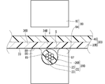
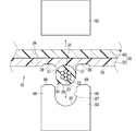
- FIG.3 and FIG.4 is a figure explaining a mode that the wire harness 10 which concerns on embodiment is manufactured.
- description of the electric wire 20B etc. which are shown in FIG.3 and FIG.4 has shown that it is the state before welding. That is, in the following, when it is necessary to distinguish the wire and sheet material before welding and their respective parts from those after welding, those indicating the state before welding may be described with reference B.
- the wire harness 10 is manufactured by ultrasonically welding the electric wire 20B and the sheet material 30B with the ultrasonic welding machine 80.
- the ultrasonic welder 80 includes a horn 82 and an anvil 84.
- the horn 82 is a member that applies ultrasonic vibration to a workpiece that comes into contact. It is also conceivable that the surface of the horn 82 that comes into contact with the workpiece has a concavo-convex shape for the purpose of knurling, that is, for preventing slipping.
- the anvil 84 is a member that supports the workpiece from the opposite side with respect to the horn 82. Therefore, in a state where the pair of parts to be welded in the workpiece are sandwiched between the horn 82 and the anvil 84, ultrasonic vibration is applied and the workpiece is welded.
- the electric wire 20B and the electric wire 20B are arranged while the electric wire 20B is arranged on the electric wire arranging portion 34B formed softer than the insulating coating 26B in the resin sheet material 30B.
- the part 34B is clamped by a clamping member.
- the anvil 84 is disposed while the electric wire 20B before welding is arranged at a predetermined position (electric wire arrangement portion 34B) on the main surface 33 on the first layer 32 side of the sheet material 30B before welding. Support by.
- the horn 82 is approached toward the anvil 84, the electric wire 20B and the sheet material 30B are sandwiched by the horn 82 and the anvil 84, and the insulating coating 26B and the electric wire arrangement portion 34B are brought into contact with each other.
- the horn 82 is arranged to hold the sheet material 30B side and the anvil 84 is arranged to hold the electric wire 20B side, but the horn is arranged to hold the electric wire 20B side and the anvil is pressed to the sheet material 30B side. The case where it is done is also considered.
- the width dimension of the horn 82 is set larger than the diameter of the electric wire 20B. Thereby, the horn 82 can be brought into contact with not only the electric wire arrangement part 34B but also the electric wire non-arrangement part 36B on the side of the electric wire arrangement part 34B in the sheet material 30B. And the horn 82 is comprised so that the electric wire non-arrangement part 36B in this sheet material 30B may be clamped with the anvil 84.
- a holding groove 85 for holding the electric wire 20B is formed on the surface of the anvil 84 facing the horn 82 side.
- a holding portion 89 that presses the electric wire non-arranged portion 36 ⁇ / b> B of the sheet material 30 together with the horn 82 is formed on the side portion of the holding groove 85.
- the bottom of the holding groove 85 may be flat or curved. In the example shown in FIG. 3, the bottom of the holding groove 85 is formed in a curved surface shape.
- the holding portion 89 is positioned at the same height as the electric wire 20B in a state where the electric wire 20B is received in the holding groove 85.
- the holding portion 89 is positioned at a height equal to or higher than that of the electric wire 20B in a state where the electric wire 20B is received in the holding groove 85.
- the holding portion 89 protrudes slightly higher than the electric wire 20 ⁇ / b> B in a state where the electric wire 20 ⁇ / b> B is received in the holding groove 85.
- the depth of the holding groove 85 is set to be approximately the same as the diameter of the electric wire 20B (slightly larger than the diameter of the electric wire 20B in the example shown in FIG. 3).
- the distal end portion of 86 also serves as a presser portion 89.
- the presser part 89 is configured so as to sandwich a portion where the electric wire 20 ⁇ / b> B is not provided in the sheet material 30 ⁇ / b> B together with the horn 82.
- the pressing portion 89 does not press up to the edge portion of the sheet material 30B, and presses only the intermediate portion of the sheet material 30B. For this reason, the recessed part 39 is formed in the part pressed by the pressing part 89 in the main surface 33 of the sheet
- the edge portion of the presser portion 89 is chamfered, but it may be chamfered. In the case of chamfering, in the example shown in FIG. 3, it is formed in the shape of a square surface, but may be formed in a shape such as a round surface.
- the width of the opening is closer to the opening than the bottom of the holding groove 85 formed in the curved surface. For this reason, the inner surface of the wall 86 extending from the bottom of the holding groove 85 to the tip of the presser 89 is a vertical surface 87.
- the wire harness 10 is preferably thin.
- the sheet material 30B is preferably thin.
- the thickness dimension of the first layer 32B before welding is set smaller than the diameter of the electric wire 20B.
- the thickness dimension of the first layer 32B before welding may be the same as the diameter of the electric wire 20B, or may be set larger than the diameter of the electric wire 20B.
- the thickness dimension of the first layer 32B before welding is set to be smaller than the radius of the electric wire 20B.
- the thickness dimension of the first layer 32B before welding may be the same as the radius of the electric wire 20B, or may be set larger than the radius of the electric wire 20B.
- the thickness dimension of the first layer 32B before welding is set larger than the thickness dimension of the insulating coating 26B (herein, the average thickness dimension in view of the presence of the plurality of strands 23).
- the thickness dimension of the first layer 32B before welding may be the same as the thickness dimension of the insulating coating 26B, or may be set smaller than the thickness dimension of the insulating coating 26B.
- the insulation coating 26B and the electric wire arrangement part 34B are ultrasonically welded in a state where the electric wire 20B and the electric wire arrangement part 34B are held by the holding member.
- ultrasonic vibration is applied by the horn 82 in a state where the portion where the insulating coating 26B and the sheet material 30B are in contact with each other is sandwiched by the horn 82 and the anvil 84.
- the horn 82 presses the sheet material 30B side
- ultrasonic vibration is applied from the sheet material 30B side. Friction heat resulting from ultrasonic vibration is generated at the portion where the insulating coating 26B and the sheet material 30B are in contact with each other, and at least one of them is melted to join them.
- both the insulation coating 26B and the sheet material 30B are formed of a PVC-based material, both are melted and joined.
- both the insulation coating 26B and the electric wire arrangement portion 34B are formed of a material containing PVC and a plasticizer. Further, at the time before the ultrasonic welding is started, the ratio of the plasticizer to the PVC constituting the portion including the electric wire arranging portion 34B is higher than the ratio of the plasticizer to the PVC constituting the insulating coating 26B. This state is continued even at the time when ultrasonic welding is performed, and at the time when ultrasonic welding is performed, the portion including the electric wire arrangement portion 34B is softer than the insulating coating 26B. It has become.
- the electric wire arrangement portion 34B is softer than the insulating coating 26B, so that the horn 82 and the anvil 84 are in contact with the electric wire arrangement portion 34B and the insulating coating 26B.
- the force relating to the pressurization due to is likely to act as a force for deforming the electric wire arrangement portion 34B.
- the boundary surface between the electric wire fixing portion 34 and the insulating coating 26B formed by welding the electric wire arranging portion 34B has an original outer periphery of the insulating coating 26 rather than the shape of the main surface 33 of the electric wire arranging portion 34B before welding. It is formed in a shape close to a circumferential surface shape that is a surface.
- the circumferential surface shape which is the original outer peripheral surface of the insulation coating 26 can be confirmed in the portion where there is a portion that is not welded along the longitudinal direction of the electric wire 20, for example. Further, here, even in the portion welded along the longitudinal direction of the electric wire 20, the surface opposite to the surface to be welded is not easily deformed when welded. The shape can also be confirmed.
- the pressing portion 89 is formed on the anvil 84 and a part of the sheet material 30B is sandwiched between the pressing portion 89 and the horn 82, the first layer of the sheet material 30B pressed by the pressing portion 89 is provided. A part of 32B is brought closer to the holding groove 85 side. More specifically, the portion of the sheet material 30B that is pressed by the holding portion 89 is located in the immediate vicinity of the portion where the electric wire 20B and the sheet material 30B are in contact with each other, and thus is generated at the portion where the electric wire 20B and the sheet material 30B are in contact. It is conceivable that the frictional heat reaches the portion pressed by the pressing portion 89 in the sheet material 30B.
- the electric wire arranging portion 34B is held by the electric wire 20B, the horn 82, and the anvil 84, since the holding portions 89 exist on both sides, the electric wire arranging portion 34B is deformed so that the thickness is reduced. Hateful.
- the wire fixing portion 34 is easily raised by pressing the sheet material 30B by the holding portion 89.
- the holding portions 89 are formed on both sides of the holding groove 85, the wire fixing portion 34 is easily raised on both sides with respect to the center line passing through the center of the wire 20.
- the sheet material 30 is welded extensively in the circumferential direction of the electric wire 20 while suppressing a decrease in the dimension A.
- the gap S generated on the side of the portion where the two contact each other between the electric wire 20 ⁇ / b> B and the sheet material 30 ⁇ / b> B before welding is filled with the deformed portion 35 of the sheet material 30.
- the wire fixing portion 34 can be raised by bringing the wire non-arranged portion 36B of the sheet material 30B closer to the electric wire disposed portion 34B. Thereby, thickness required for the electric wire fixing
- the portion of the concave portion 39 that is recessed in the side portion of the electric wire 20 in the sheet material 30 is brought close to the electric wire fixing portion 34, so that the electric wire fixing portion 34 is easily raised greatly.
- the wire harness 10 is manufactured by the temperature heated by the frictional heat at the time when ultrasonic welding is performed and the electric wire arrangement portion 34B being softer than the insulating coating 26B in a pressurized state.
- the softness of the sheet material 30 and the insulating coating 26 is adjusted using a plasticizer.
- the plasticizer may move to a contact member over time. For this reason, after ultrasonic welding, the plasticizer may be transferred between the wire fixing portion 34 and the insulating coating 26.
- the plasticizer of the wire fixing portion 34 and the plasticizer of the insulating coating 26 are in an equilibrium state, and the wire fixing portion 34 and the insulating coating 26 have the same hardness.
- whether the hardness of the wire fixing portion 34 is the same as the hardness of the insulating coating 26 by processing after ultrasonic welding (for example, only the wire fixing portion 34 of the electric wire 20 and the wire fixing portion 34 is heated and pressed). It may be harder than that. Even in these cases, it is considered that the boundary surface between the wire fixing portion 34 and the insulating coating 26 remains in a shape along the outer peripheral surface of the insulating coating 26.
- the electric wire fixing portion 34 can be formed softer than the insulating coating 26.
- the sheet material 30 includes the first layer 32 as the electric wire fixing layer 32 and the second layer 40 laminated on the first layer 32, the sheet material 30 has physical properties suitable for fixing the electric wire 20 and the sheet. It becomes easy to impart desired performance to the material 30 with the second layer 40.
- FIG. 5 is a cross-sectional view showing a wire harness 110 according to a first modification.
- the sheet material 30 has been described as having a two-layer structure, but this is not an essential configuration.
- the sheet material 130 may be a single layer composed of the electric wire fixing layer 32.
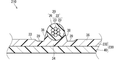
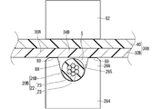
- FIG. 6 is a cross-sectional view showing a wire harness 210 according to a second modification.
- FIG. 7 is a diagram for explaining a state of manufacturing the wire harness 210 according to the second modification.
- the vertical surface 37 is directed from the end of the boundary surface of the welding toward the electric wire non-arranged portion 36 of the sheet material 30, but this is not an essential configuration.
- the inclined surface 38 is formed from the end portion of the boundary surface of welding toward the electric wire non-arranged portion 36.
- the inclined surface 38 is formed in a side portion of the electric wire 20 on the main surface 33 of the sheet material 230 in such a manner that the height along the thickness direction decreases as the distance from the electric wire 20 increases.
- the inner surface of the holding groove 285 formed on the anvil 284 (the inner surface of the wall portion 286) has an inclined surface 88 in which the surface from the bottom to the opening gradually becomes wider toward the opening. Accordingly, the inclined surface 38 of the sheet material 230 can be formed together during ultrasonic welding. At this time, since the inclined surface 88 is formed on the anvil 284, a portion of the sheet material 30B that is pressed by the presser portion 89 in the wire non-placed portion 36B is easily brought close to the wire placed portion 34B.
- the wire fixing part 34 has been described so far as being softer than the insulating coating 26 in the wire harness 10, this is not an essential configuration.
- the wire fixing portion 34 may be the same hardness as the insulating coating 26 or harder than the insulating coating 26.
- the electric wire arranging portion 34B is softer than the insulating coating 26B, but this is not an essential configuration.
- the electric wire arrangement part 34B may be the same hardness as the insulating coating 26B or harder than the insulating coating 26B. Even in these cases, the dimension B can be made larger than the dimensions C and D by changing the thickness of the sheet material before welding or by ultrasonic welding using the anvil 84 having the holding portion 89. it can.
- the main surface 33 of the sheet material 30 has been described as having the concave portions 39 formed in the side portions of the electric wires 20, but this is not an essential configuration.
- the concave portion 39 is not formed in the side portion of the electric wire 20 in the main surface 33 of the sheet material 30.
- the pressing portion 89 of the anvil 84 presses the entire wire non-arranged portion 36B of the sheet material 30, or the anvil is not provided with the pressing portion 89, the anvil contacts the electric wire non-arranged portion 36B of the sheet material 30.
- the concave portion 39 is not formed, for example, when not.
- the side portion of the electric wire 20 in the sheet material 30 has been described as a series of vertical surfaces 37 or inclined surfaces 38, but this is not an essential configuration. It is also conceivable that the side portion of the electric wire 20 in the sheet material 30 is formed in a stepped shape.
- the inner surface of the wall portion 86 extending from the bottom of the holding groove 85 to the tip of the holding portion 89 is formed in a stepped shape, so that the side portion of the electric wire 20 in the sheet material 30 is formed in a stepped shape. It can be considered.
- the electric wire 20 has been described as a round electric wire so far, but this is not an essential configuration.
- the electric wire 20 may be an electric wire other than a round electric wire such as a square electric wire.
- the insulating coating 26 and the wire fixing layer 32 are formed of a PVC-based material, this is not an essential configuration.
- the insulating coating 26 and the wire fixing layer 32 may be formed of a material based on PE or PP.
- the density of the PE or PP used as the base of the wire fixing layer 32 is made lower than that of the PE or PP used as the base of the insulating coating 26, or the PE or PP used as the base of the wire fixing layer 32 is reacted with isobutylene or the like. By doing so, the electric wire fixing layer 32 can be made softer than the insulating coating 26.
- the electric wire fixing layer 32 has been described as being softer than the insulating coating 26 by changing the ratio of the plasticizer. This is not an essential configuration.
- the wire fixing layer 32 can be formed softer than the insulating coating 26 by making the polymerization degree of PVC constituting the wire fixing layer 32 lower than the polymerization degree of PVC constituting the insulating coating 26.
- both the proportion of the plasticizer and the degree of polymerization are changed to be soft.
- it may be softened by changing only the proportion of the plasticizer, or may be softened by changing only the degree of polymerization.
- the second layer 40 has been described as being harder than the first layer 32 with a resin material for the purpose of improving shape retention or wear resistance, but this is not an essential configuration.
- a metal foil such as an aluminum foil as the second layer 40, it is conceivable that the sheet material 30 is configured to have a shielding property or enhance a heat dissipation property.
- the sheet material 30 may have a three-layer structure or more. That is, it is conceivable that the third layer and the fourth layer are sequentially laminated on the opposite side of the second layer from the first layer.
- the second layer is a layer in which a plasticizer formed of a material such as PP or PET is difficult to migrate
- the third layer is a layer formed of PVC, which is a first layer.
- a layer harder than 32 (a layer corresponding to the second layer 40 in the above embodiment) may be considered.
- the second layer functions as a barrier layer that suppresses the migration of the plasticizer from the first layer to the third layer.
- the insulating coating 26 and the wire fixing layer 32 have been described as being ultrasonically welded, but this is not an essential configuration.
- the insulating coating 26 and the wire fixing layer 32 may be welded by welding means other than ultrasonic welding such as hot air welding or high frequency welding.
- the additive added in addition to the plasticizer may be added within a range that does not hinder the hardness determined by the amount of the plasticizer.
- examples of such additives include heat stabilizers, inorganic fillers (eg, calcium carbonate, talc, silica, clay, etc.), rubber materials (eg, chlorinated polyethylene (CPE), methyl methacrylate / butadiene / styrene copolymer resins). (MBS), polyurethane elastomer, ethylene / vinyl acetate copolymer resin (EVA) and the like) may be added.
- CPE chlorinated polyethylene
- MVS chlorinated polyethylene
- EVA ethylene / vinyl acetate copolymer resin
Landscapes
- Engineering & Computer Science (AREA)
- Manufacturing & Machinery (AREA)
- Mechanical Engineering (AREA)
- Details Of Indoor Wiring (AREA)
- Insulated Conductors (AREA)
Priority Applications (3)
| Application Number | Priority Date | Filing Date | Title |
|---|---|---|---|
| CN201980021077.8A CN111937091B (zh) | 2018-03-28 | 2019-03-07 | 线束和线束的制造方法 |
| DE112019001624.5T DE112019001624T5 (de) | 2018-03-28 | 2019-03-07 | Kabelstrang und Verfahren zur Herstellung eines Kabelstrangs |
| US16/981,789 US11183319B2 (en) | 2018-03-28 | 2019-03-07 | Wire harness and method of manufacturing wire harness |
Applications Claiming Priority (2)
| Application Number | Priority Date | Filing Date | Title |
|---|---|---|---|
| JP2018-061265 | 2018-03-28 | ||
| JP2018061265A JP6665881B2 (ja) | 2018-03-28 | 2018-03-28 | ワイヤーハーネス及びワイヤーハーネスの製造方法 |
Publications (1)
| Publication Number | Publication Date |
|---|---|
| WO2019188080A1 true WO2019188080A1 (ja) | 2019-10-03 |
Family
ID=68059826
Family Applications (1)
| Application Number | Title | Priority Date | Filing Date |
|---|---|---|---|
| PCT/JP2019/009000 Ceased WO2019188080A1 (ja) | 2018-03-28 | 2019-03-07 | ワイヤーハーネス及びワイヤーハーネスの製造方法 |
Country Status (5)
| Country | Link |
|---|---|
| US (1) | US11183319B2 (enExample) |
| JP (1) | JP6665881B2 (enExample) |
| CN (1) | CN111937091B (enExample) |
| DE (1) | DE112019001624T5 (enExample) |
| WO (1) | WO2019188080A1 (enExample) |
Families Citing this family (1)
| Publication number | Priority date | Publication date | Assignee | Title |
|---|---|---|---|---|
| US11521764B2 (en) * | 2018-03-28 | 2022-12-06 | Autonetworks Technologies, Ltd. | Wire harness and method of manufacturing wire harness |
Citations (2)
| Publication number | Priority date | Publication date | Assignee | Title |
|---|---|---|---|---|
| JP2002216871A (ja) * | 2001-01-19 | 2002-08-02 | Yazaki Corp | 電線付き導体薄膜シートと該電線付き導体薄膜シートの製造方法 |
| JP2002343156A (ja) * | 2001-05-18 | 2002-11-29 | Yazaki Corp | シールドハーネスの組立方法 |
Family Cites Families (10)
| Publication number | Priority date | Publication date | Assignee | Title |
|---|---|---|---|---|
| JPS5054597A (enExample) | 1973-09-06 | 1975-05-14 | ||
| JPS5054597U (enExample) * | 1973-09-14 | 1975-05-24 | ||
| JPH0636330B2 (ja) * | 1985-06-17 | 1994-05-11 | 矢崎総業株式会社 | ワイヤ−ハ−ネスの製造方法 |
| AU4173197A (en) | 1996-10-18 | 1998-05-15 | W.L. Gore & Associates, Inc. | Microminiature planar signal transmission cable |
| JP2002080819A (ja) * | 2000-09-06 | 2002-03-22 | Tentac Co Ltd | 熱接着フィルム |
| JP2004356022A (ja) | 2003-05-30 | 2004-12-16 | Yazaki Corp | ワイヤハーネスの組立方法とワイヤハーネス |
| CN101151684B (zh) * | 2005-03-31 | 2011-12-07 | 株式会社润工社 | 扁形电缆 |
| JP5375408B2 (ja) * | 2009-07-24 | 2013-12-25 | 住友電気工業株式会社 | 同軸線ハーネス |
| JP5710233B2 (ja) | 2010-12-10 | 2015-04-30 | 矢崎総業株式会社 | ワイヤハーネスの製造方法 |
| JP5979113B2 (ja) | 2013-10-03 | 2016-08-24 | 住友電装株式会社 | ワイヤハーネス |
-
2018
- 2018-03-28 JP JP2018061265A patent/JP6665881B2/ja active Active
-
2019
- 2019-03-07 DE DE112019001624.5T patent/DE112019001624T5/de active Pending
- 2019-03-07 WO PCT/JP2019/009000 patent/WO2019188080A1/ja not_active Ceased
- 2019-03-07 US US16/981,789 patent/US11183319B2/en active Active
- 2019-03-07 CN CN201980021077.8A patent/CN111937091B/zh active Active
Patent Citations (2)
| Publication number | Priority date | Publication date | Assignee | Title |
|---|---|---|---|---|
| JP2002216871A (ja) * | 2001-01-19 | 2002-08-02 | Yazaki Corp | 電線付き導体薄膜シートと該電線付き導体薄膜シートの製造方法 |
| JP2002343156A (ja) * | 2001-05-18 | 2002-11-29 | Yazaki Corp | シールドハーネスの組立方法 |
Also Published As
| Publication number | Publication date |
|---|---|
| CN111937091A (zh) | 2020-11-13 |
| JP6665881B2 (ja) | 2020-03-13 |
| CN111937091B (zh) | 2022-05-13 |
| DE112019001624T5 (de) | 2020-12-10 |
| US20210134490A1 (en) | 2021-05-06 |
| JP2019175638A (ja) | 2019-10-10 |
| US11183319B2 (en) | 2021-11-23 |
Similar Documents
| Publication | Publication Date | Title |
|---|---|---|
| JP2019003925A (ja) | ワイヤーハーネスおよびワイヤーハーネスの製造方法 | |
| CN112154522B (zh) | 配线部件 | |
| JP6365704B1 (ja) | ワイヤーハーネス | |
| US11501898B2 (en) | Wire harness and method of manufacturing wire harness | |
| JP7147839B2 (ja) | ワイヤーハーネスおよびワイヤーハーネスの製造方法 | |
| WO2019189177A1 (ja) | ワイヤーハーネス | |
| JP2022000861A (ja) | 端子付き電線、及び端子付き電線の製造方法 | |
| WO2018235788A1 (ja) | ワイヤーハーネスおよびワイヤーハーネスの製造方法 | |
| WO2019188080A1 (ja) | ワイヤーハーネス及びワイヤーハーネスの製造方法 | |
| JP7192628B2 (ja) | 配線部材 | |
| JP2019179630A5 (enExample) | ||
| JP6923023B2 (ja) | ワイヤーハーネス及びワイヤーハーネスの製造方法 | |
| JP2018156961A (ja) | ワイヤーハーネス | |
| WO2023136216A1 (ja) | 配線部材及び配線部材の製造方法 | |
| JP7056621B2 (ja) | 配線部材 | |
| WO2020039914A1 (ja) | 配線部材 | |
| WO2025263401A1 (ja) | 配線部材 | |
| JP2020092097A5 (enExample) | ||
| WO2025142486A1 (ja) | 配線部材及び配線部材の製造方法 | |
| JPS6386383A (ja) | ヒ−タユニツトの製造法 | |
| JP2005312143A (ja) | フラットケーブルの固定構造 | |
| JPS6386382A (ja) | ヒ−タユニツトの製造法 |
Legal Events
| Date | Code | Title | Description |
|---|---|---|---|
| 121 | Ep: the epo has been informed by wipo that ep was designated in this application |
Ref document number: 19776579 Country of ref document: EP Kind code of ref document: A1 |
|
| 122 | Ep: pct application non-entry in european phase |
Ref document number: 19776579 Country of ref document: EP Kind code of ref document: A1 |