WO2019187807A1 - 電動ブレーキシステム、液圧制御回路、および、液量制御回路 - Google Patents
電動ブレーキシステム、液圧制御回路、および、液量制御回路 Download PDFInfo
- Publication number
- WO2019187807A1 WO2019187807A1 PCT/JP2019/006212 JP2019006212W WO2019187807A1 WO 2019187807 A1 WO2019187807 A1 WO 2019187807A1 JP 2019006212 W JP2019006212 W JP 2019006212W WO 2019187807 A1 WO2019187807 A1 WO 2019187807A1
- Authority
- WO
- WIPO (PCT)
- Prior art keywords
- liquid
- characteristic
- hydraulic pressure
- master cylinder
- pressure
- Prior art date
- Legal status (The legal status is an assumption and is not a legal conclusion. Google has not performed a legal analysis and makes no representation as to the accuracy of the status listed.)
- Ceased
Links
Images






Classifications
-
- B—PERFORMING OPERATIONS; TRANSPORTING
- B60—VEHICLES IN GENERAL
- B60T—VEHICLE BRAKE CONTROL SYSTEMS OR PARTS THEREOF; BRAKE CONTROL SYSTEMS OR PARTS THEREOF, IN GENERAL; ARRANGEMENT OF BRAKING ELEMENTS ON VEHICLES IN GENERAL; PORTABLE DEVICES FOR PREVENTING UNWANTED MOVEMENT OF VEHICLES; VEHICLE MODIFICATIONS TO FACILITATE COOLING OF BRAKES
- B60T13/00—Transmitting braking action from initiating means to ultimate brake actuator with power assistance or drive; Brake systems incorporating such transmitting means, e.g. air-pressure brake systems
- B60T13/10—Transmitting braking action from initiating means to ultimate brake actuator with power assistance or drive; Brake systems incorporating such transmitting means, e.g. air-pressure brake systems with fluid assistance, drive, or release
- B60T13/66—Electrical control in fluid-pressure brake systems
- B60T13/68—Electrical control in fluid-pressure brake systems by electrically-controlled valves
- B60T13/686—Electrical control in fluid-pressure brake systems by electrically-controlled valves in hydraulic systems or parts thereof
-
- B—PERFORMING OPERATIONS; TRANSPORTING
- B60—VEHICLES IN GENERAL
- B60T—VEHICLE BRAKE CONTROL SYSTEMS OR PARTS THEREOF; BRAKE CONTROL SYSTEMS OR PARTS THEREOF, IN GENERAL; ARRANGEMENT OF BRAKING ELEMENTS ON VEHICLES IN GENERAL; PORTABLE DEVICES FOR PREVENTING UNWANTED MOVEMENT OF VEHICLES; VEHICLE MODIFICATIONS TO FACILITATE COOLING OF BRAKES
- B60T8/00—Arrangements for adjusting wheel-braking force to meet varying vehicular or ground-surface conditions, e.g. limiting or varying distribution of braking force
- B60T8/17—Using electrical or electronic regulation means to control braking
-
- B—PERFORMING OPERATIONS; TRANSPORTING
- B60—VEHICLES IN GENERAL
- B60T—VEHICLE BRAKE CONTROL SYSTEMS OR PARTS THEREOF; BRAKE CONTROL SYSTEMS OR PARTS THEREOF, IN GENERAL; ARRANGEMENT OF BRAKING ELEMENTS ON VEHICLES IN GENERAL; PORTABLE DEVICES FOR PREVENTING UNWANTED MOVEMENT OF VEHICLES; VEHICLE MODIFICATIONS TO FACILITATE COOLING OF BRAKES
- B60T17/00—Component parts, details, or accessories of power brake systems not covered by groups B60T8/00, B60T13/00 or B60T15/00, or presenting other characteristic features
- B60T17/18—Safety devices; Monitoring
-
- B—PERFORMING OPERATIONS; TRANSPORTING
- B60—VEHICLES IN GENERAL
- B60T—VEHICLE BRAKE CONTROL SYSTEMS OR PARTS THEREOF; BRAKE CONTROL SYSTEMS OR PARTS THEREOF, IN GENERAL; ARRANGEMENT OF BRAKING ELEMENTS ON VEHICLES IN GENERAL; PORTABLE DEVICES FOR PREVENTING UNWANTED MOVEMENT OF VEHICLES; VEHICLE MODIFICATIONS TO FACILITATE COOLING OF BRAKES
- B60T13/00—Transmitting braking action from initiating means to ultimate brake actuator with power assistance or drive; Brake systems incorporating such transmitting means, e.g. air-pressure brake systems
- B60T13/10—Transmitting braking action from initiating means to ultimate brake actuator with power assistance or drive; Brake systems incorporating such transmitting means, e.g. air-pressure brake systems with fluid assistance, drive, or release
- B60T13/12—Transmitting braking action from initiating means to ultimate brake actuator with power assistance or drive; Brake systems incorporating such transmitting means, e.g. air-pressure brake systems with fluid assistance, drive, or release the fluid being liquid
- B60T13/16—Transmitting braking action from initiating means to ultimate brake actuator with power assistance or drive; Brake systems incorporating such transmitting means, e.g. air-pressure brake systems with fluid assistance, drive, or release the fluid being liquid using pumps directly, i.e. without interposition of accumulators or reservoirs
- B60T13/161—Systems with master cylinder
- B60T13/165—Master cylinder integrated or hydraulically coupled with booster
- B60T13/166—Part of the system directly actuated by booster pressure
-
- B—PERFORMING OPERATIONS; TRANSPORTING
- B60—VEHICLES IN GENERAL
- B60T—VEHICLE BRAKE CONTROL SYSTEMS OR PARTS THEREOF; BRAKE CONTROL SYSTEMS OR PARTS THEREOF, IN GENERAL; ARRANGEMENT OF BRAKING ELEMENTS ON VEHICLES IN GENERAL; PORTABLE DEVICES FOR PREVENTING UNWANTED MOVEMENT OF VEHICLES; VEHICLE MODIFICATIONS TO FACILITATE COOLING OF BRAKES
- B60T13/00—Transmitting braking action from initiating means to ultimate brake actuator with power assistance or drive; Brake systems incorporating such transmitting means, e.g. air-pressure brake systems
- B60T13/10—Transmitting braking action from initiating means to ultimate brake actuator with power assistance or drive; Brake systems incorporating such transmitting means, e.g. air-pressure brake systems with fluid assistance, drive, or release
- B60T13/58—Combined or convertible systems
-
- B—PERFORMING OPERATIONS; TRANSPORTING
- B60—VEHICLES IN GENERAL
- B60T—VEHICLE BRAKE CONTROL SYSTEMS OR PARTS THEREOF; BRAKE CONTROL SYSTEMS OR PARTS THEREOF, IN GENERAL; ARRANGEMENT OF BRAKING ELEMENTS ON VEHICLES IN GENERAL; PORTABLE DEVICES FOR PREVENTING UNWANTED MOVEMENT OF VEHICLES; VEHICLE MODIFICATIONS TO FACILITATE COOLING OF BRAKES
- B60T13/00—Transmitting braking action from initiating means to ultimate brake actuator with power assistance or drive; Brake systems incorporating such transmitting means, e.g. air-pressure brake systems
- B60T13/10—Transmitting braking action from initiating means to ultimate brake actuator with power assistance or drive; Brake systems incorporating such transmitting means, e.g. air-pressure brake systems with fluid assistance, drive, or release
- B60T13/66—Electrical control in fluid-pressure brake systems
- B60T13/662—Electrical control in fluid-pressure brake systems characterised by specified functions of the control system components
-
- B—PERFORMING OPERATIONS; TRANSPORTING
- B60—VEHICLES IN GENERAL
- B60T—VEHICLE BRAKE CONTROL SYSTEMS OR PARTS THEREOF; BRAKE CONTROL SYSTEMS OR PARTS THEREOF, IN GENERAL; ARRANGEMENT OF BRAKING ELEMENTS ON VEHICLES IN GENERAL; PORTABLE DEVICES FOR PREVENTING UNWANTED MOVEMENT OF VEHICLES; VEHICLE MODIFICATIONS TO FACILITATE COOLING OF BRAKES
- B60T13/00—Transmitting braking action from initiating means to ultimate brake actuator with power assistance or drive; Brake systems incorporating such transmitting means, e.g. air-pressure brake systems
- B60T13/74—Transmitting braking action from initiating means to ultimate brake actuator with power assistance or drive; Brake systems incorporating such transmitting means, e.g. air-pressure brake systems with electrical assistance or drive
- B60T13/741—Transmitting braking action from initiating means to ultimate brake actuator with power assistance or drive; Brake systems incorporating such transmitting means, e.g. air-pressure brake systems with electrical assistance or drive acting on an ultimate actuator
-
- B—PERFORMING OPERATIONS; TRANSPORTING
- B60—VEHICLES IN GENERAL
- B60T—VEHICLE BRAKE CONTROL SYSTEMS OR PARTS THEREOF; BRAKE CONTROL SYSTEMS OR PARTS THEREOF, IN GENERAL; ARRANGEMENT OF BRAKING ELEMENTS ON VEHICLES IN GENERAL; PORTABLE DEVICES FOR PREVENTING UNWANTED MOVEMENT OF VEHICLES; VEHICLE MODIFICATIONS TO FACILITATE COOLING OF BRAKES
- B60T13/00—Transmitting braking action from initiating means to ultimate brake actuator with power assistance or drive; Brake systems incorporating such transmitting means, e.g. air-pressure brake systems
- B60T13/74—Transmitting braking action from initiating means to ultimate brake actuator with power assistance or drive; Brake systems incorporating such transmitting means, e.g. air-pressure brake systems with electrical assistance or drive
- B60T13/745—Transmitting braking action from initiating means to ultimate brake actuator with power assistance or drive; Brake systems incorporating such transmitting means, e.g. air-pressure brake systems with electrical assistance or drive acting on a hydraulic system, e.g. a master cylinder
-
- B—PERFORMING OPERATIONS; TRANSPORTING
- B60—VEHICLES IN GENERAL
- B60T—VEHICLE BRAKE CONTROL SYSTEMS OR PARTS THEREOF; BRAKE CONTROL SYSTEMS OR PARTS THEREOF, IN GENERAL; ARRANGEMENT OF BRAKING ELEMENTS ON VEHICLES IN GENERAL; PORTABLE DEVICES FOR PREVENTING UNWANTED MOVEMENT OF VEHICLES; VEHICLE MODIFICATIONS TO FACILITATE COOLING OF BRAKES
- B60T7/00—Brake-action initiating means
- B60T7/02—Brake-action initiating means for personal initiation
- B60T7/04—Brake-action initiating means for personal initiation foot actuated
- B60T7/042—Brake-action initiating means for personal initiation foot actuated by electrical means, e.g. using travel or force sensors
-
- B—PERFORMING OPERATIONS; TRANSPORTING
- B60—VEHICLES IN GENERAL
- B60T—VEHICLE BRAKE CONTROL SYSTEMS OR PARTS THEREOF; BRAKE CONTROL SYSTEMS OR PARTS THEREOF, IN GENERAL; ARRANGEMENT OF BRAKING ELEMENTS ON VEHICLES IN GENERAL; PORTABLE DEVICES FOR PREVENTING UNWANTED MOVEMENT OF VEHICLES; VEHICLE MODIFICATIONS TO FACILITATE COOLING OF BRAKES
- B60T13/00—Transmitting braking action from initiating means to ultimate brake actuator with power assistance or drive; Brake systems incorporating such transmitting means, e.g. air-pressure brake systems
- B60T13/10—Transmitting braking action from initiating means to ultimate brake actuator with power assistance or drive; Brake systems incorporating such transmitting means, e.g. air-pressure brake systems with fluid assistance, drive, or release
- B60T13/12—Transmitting braking action from initiating means to ultimate brake actuator with power assistance or drive; Brake systems incorporating such transmitting means, e.g. air-pressure brake systems with fluid assistance, drive, or release the fluid being liquid
- B60T13/16—Transmitting braking action from initiating means to ultimate brake actuator with power assistance or drive; Brake systems incorporating such transmitting means, e.g. air-pressure brake systems with fluid assistance, drive, or release the fluid being liquid using pumps directly, i.e. without interposition of accumulators or reservoirs
- B60T13/161—Systems with master cylinder
-
- B—PERFORMING OPERATIONS; TRANSPORTING
- B60—VEHICLES IN GENERAL
- B60T—VEHICLE BRAKE CONTROL SYSTEMS OR PARTS THEREOF; BRAKE CONTROL SYSTEMS OR PARTS THEREOF, IN GENERAL; ARRANGEMENT OF BRAKING ELEMENTS ON VEHICLES IN GENERAL; PORTABLE DEVICES FOR PREVENTING UNWANTED MOVEMENT OF VEHICLES; VEHICLE MODIFICATIONS TO FACILITATE COOLING OF BRAKES
- B60T2270/00—Further aspects of brake control systems not otherwise provided for
- B60T2270/10—ABS control systems
- B60T2270/14—ABS control systems hydraulic model
-
- B—PERFORMING OPERATIONS; TRANSPORTING
- B60—VEHICLES IN GENERAL
- B60T—VEHICLE BRAKE CONTROL SYSTEMS OR PARTS THEREOF; BRAKE CONTROL SYSTEMS OR PARTS THEREOF, IN GENERAL; ARRANGEMENT OF BRAKING ELEMENTS ON VEHICLES IN GENERAL; PORTABLE DEVICES FOR PREVENTING UNWANTED MOVEMENT OF VEHICLES; VEHICLE MODIFICATIONS TO FACILITATE COOLING OF BRAKES
- B60T2270/00—Further aspects of brake control systems not otherwise provided for
- B60T2270/40—Failsafe aspects of brake control systems
- B60T2270/402—Back-up
-
- B—PERFORMING OPERATIONS; TRANSPORTING
- B60—VEHICLES IN GENERAL
- B60T—VEHICLE BRAKE CONTROL SYSTEMS OR PARTS THEREOF; BRAKE CONTROL SYSTEMS OR PARTS THEREOF, IN GENERAL; ARRANGEMENT OF BRAKING ELEMENTS ON VEHICLES IN GENERAL; PORTABLE DEVICES FOR PREVENTING UNWANTED MOVEMENT OF VEHICLES; VEHICLE MODIFICATIONS TO FACILITATE COOLING OF BRAKES
- B60T2270/00—Further aspects of brake control systems not otherwise provided for
- B60T2270/88—Pressure measurement in brake systems
-
- B—PERFORMING OPERATIONS; TRANSPORTING
- B60—VEHICLES IN GENERAL
- B60Y—INDEXING SCHEME RELATING TO ASPECTS CROSS-CUTTING VEHICLE TECHNOLOGY
- B60Y2400/00—Special features of vehicle units
- B60Y2400/81—Braking systems
Definitions
- the present invention relates to an electric brake system for applying braking force to a vehicle such as an automobile, a fluid pressure control circuit, and a fluid amount control circuit.
- Patent Document 1 describes a technique for detecting and determining a failure state of an electric booster by transmitting the state of the electric booster to a liquid amount supply device (ESC) via a communication line.
- ESC liquid amount supply device
- Patent Document 2 describes a technique for controlling a motor of an electric booster according to a target hydraulic pressure value calculated based on hydraulic pressure characteristic data corresponding to downstream stiffness.
- JP 2009-059882 A Japanese Unexamined Patent Publication No. 2016-193645
- the boost control can be performed by the liquid amount supply device (ESC) as a backup when the electric booster fails.
- the liquid amount supply device for example, it may be considered to calculate a discharge liquid amount necessary to generate a desired wheel cylinder pressure and to control the motor in a feedforward manner so as to obtain this discharge liquid amount. It is done.
- liquid amount / hydraulic pressure characteristic the relationship between the discharge liquid amount and the liquid pressure (hereinafter referred to as “liquid amount / hydraulic pressure characteristic”) may change due to factors such as calipers, rotors, piping, outside air temperature, liquid temperature, and empirical pressure.
- the liquid volume / pressure characteristics vary, and the control accuracy of the wheel cylinder pressure by the liquid volume supply device may be reduced.
- An object of the present invention is to provide an electric brake system, a fluid pressure control circuit, and a fluid amount control circuit that can improve the control accuracy of the wheel cylinder pressure by the fluid amount supply device (ESC).
- ESC fluid amount supply device
- An electric brake system acquires a detection value from a hydraulic pressure detection unit that detects hydraulic pressure in a master cylinder, and generates a target hydraulic pressure corresponding to a braking command in the master cylinder.
- a fluid pressure control circuit that controls driving of the electric actuator, and a fluid amount control circuit that drives a fluid amount supply device disposed between the master cylinder and the wheel cylinder to control the amount of fluid supplied to the wheel cylinder.
- a storage circuit that stores a liquid volume characteristic that is a liquid volume characteristic with respect to the detected value, and the liquid volume control circuit supplies the liquid volume based on the liquid volume characteristic stored in the storage circuit Control the device.
- a hydraulic pressure control circuit acquires a detection value from a hydraulic pressure detection unit that detects hydraulic pressure in a master cylinder, and generates a target hydraulic pressure corresponding to a braking command in the master cylinder.
- a liquid quantity control circuit is a liquid quantity control circuit that drives a liquid quantity supply device arranged between a master cylinder and a wheel cylinder to control the quantity of liquid supplied to the wheel cylinder. Then, the liquid quantity characteristic which is the characteristic of the liquid quantity with respect to the hydraulic pressure of the master cylinder is stored, and the liquid quantity supplied to the wheel cylinder is controlled based on the liquid quantity characteristic.
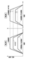
- FIG. 6 is a characteristic diagram showing an example of temporal changes in target fluid pressure, W / C pressure, target fluid amount, and discharged fluid amount before and after correction. It is explanatory drawing of the liquid quantity hydraulic pressure characteristic map correction process by a hydraulic pressure characteristic value. It is explanatory drawing of the process which offsets (corrects) a hydraulic-pressure characteristic. It is a control block diagram which shows the master cylinder pressure control unit by 2nd Embodiment. It is explanatory drawing of the liquid quantity characteristic value calculation process by the liquid quantity hydraulic pressure characteristic calculation part in FIG.
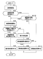
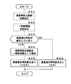
- FIG. 12 is a flowchart showing a process for determining a liquid quantity characteristic value by a liquid quantity / hydraulic pressure characteristic calculation unit in FIG. 11. It is a flowchart which shows the difference large time process of S7 in FIG. It is a flowchart which shows the process of determination whether the liquid quantity hydraulic pressure characteristic of S10 in FIG. 13 changed.
- step 1 “S1”.
- two hatched lines in FIG. 1 represent electrical lines such as signal lines (thin lines) and power supply lines (thick lines).
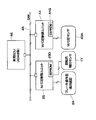
- a braking system 1 for applying braking force to four wheels that is, a left front wheel (FL), a right rear wheel (RR), a right front wheel (FR), and a left rear wheel (RL) is applied to an automobile as a vehicle.
- the brake system 1 includes hydraulic brake devices 2FL, 2RR, 2FR, 2RL as brake mechanisms mounted corresponding to the respective wheels (FL, RR, FR, RL), and these hydraulic brake devices 2FL, 2RR,
- the electric brake control device 5 is an electric brake system that controls the supply of hydraulic pressure (brake hydraulic pressure) to 2FR and 2RL.
- the electric brake control device 5 is for controlling the braking force of each wheel (FL, RR, FR, RL).
- the electric brake control device 5 includes a master cylinder 6, a master pressure control mechanism 11 integrated into the master cylinder 6, and a master cylinder pressure control unit 25 as a hydraulic pressure control circuit that controls the operation of the master pressure control mechanism 11.
- a wheel cylinder pressure control mechanism 31 as a fluid amount supply device for supplying brake fluid to the hydraulic brake devices 2FL, 2RR, 2FR, 2RL, and a fluid amount control circuit for controlling the operation of the wheel cylinder pressure control mechanism 31.
- a wheel cylinder pressure control unit 44 The electric brake control device 5 includes a reservoir tank 8, a brake pedal 9, an input rod 13, and a brake operation amount detection device 24.
- the electric brake control device 5 is supplied with electric power from a vehicle power supply 26 that is a vehicle power supply device (battery, alternator).
- the hydraulic brake devices 2FL, 2RR, 2FR, 2RL are configured as hydraulic disc brakes. That is, the hydraulic brake devices 2FL, 2RR, 2FR, 2RL include wheel cylinders 3FL, 3RR, 3FR, 3RL provided with cylinders (calipers), pistons and brake pads.
- the piston pressing member
- the piston is propelled by the hydraulic pressure supplied from the master pressure control mechanism 11 and / or the wheel cylinder pressure control mechanism 31. With the propulsion of the piston, the pair of brake pads press the disc rotors 4FL, 4RR, 4FR, 4RL so as to sandwich them.
- the disk rotors 4FL, 4RR, 4FR, 4RL rotate integrally with the wheels (FL, RR, FR, RL), respectively, and the disk rotors 4FL, 4RR, 4FR, 4RL are pressed against a pair of brake pads. Thus, a friction braking force is generated between them. As a result, the brake torque acts on the disc rotors 4FL, 4RR, 4FR, 4RL, and a braking force (braking force) is applied between the wheels (FL, RR, FR, RL) and the road surface.
- the hydraulic brake devices 2FL, 2RR, 2FR, 2RL are hydraulic disc brakes.
- the present invention is not limited to this, and other hydraulic brake mechanisms (hydraulic drum brakes such as a known hydraulic drum brake) (Pressure brake) may be employed.
- the master cylinder 6 is a tandem type having two pressurizing chambers, a primary chamber 6B pressurized by the primary piston 6A (and the input piston 12) and a secondary chamber 6D pressurized by the secondary piston 6C. .
- the primary piston 6A (and the input piston 12) is inserted into the opening side in the cylinder 6E filled with the brake fluid, and the secondary piston 6C is inserted into the bottom side of the cylinder 6E.
- the master cylinder 6 forms a primary chamber 6B between the primary piston 6A (and the input piston 12) and the secondary piston 6C, and forms a secondary chamber 6D between the secondary piston 6C and the bottom of the cylinder 6E. ing.
- the brake fluid in the primary chamber 6B is pressurized, and the secondary piston 6C is advanced to pressurize the brake fluid in the secondary chamber 6D.
- brake fluid is supplied from the primary port 6F and the secondary port 6G to the hydraulic brake devices 2FL, 2RR, 2FR, 2RL (the wheel cylinders 3FL, 3RR, 3FR, 3RL) via the wheel cylinder pressure control mechanism 31.
- the brake fluid pressurized in the primary chamber 6B and the secondary chamber 6D is hydraulic brake devices 2FL, 2RR from the primary pipeline 7A and the secondary pipeline 7B, which are master pipelines, via the wheel cylinder pressure control mechanism 31. , 2FR, 2RL.
- braking force is applied to the wheels (FL, RR, FR, RL), and deceleration occurs in the vehicle.
- the reservoir tank 8 is connected to the primary chamber 6B and the secondary chamber 6D via the reservoir ports 6H and 6H of the master cylinder 6.
- Reservoir ports 6H and 6H connect the primary chamber 6B and the secondary chamber 6D to the reservoir tank 8 respectively to supply brake fluid into the master cylinder 6 when the primary piston 6A and the secondary piston 6C are in the retracted position (original position). refill.
- the reservoir ports 6H and 6H are closed by the primary piston 6A and the secondary piston 6C as the primary piston 6A and the secondary piston 6C advance. Thereby, primary chamber 6B and secondary chamber 6D are intercepted from reservoir tank 8, and pressurization of primary chamber 6B and secondary chamber 6D is attained.
- the primary piston 6A and the secondary piston 6C are biased to the retracted position (original position) by the return springs 6J and 6J.
- the brake fluid is supplied to the two hydraulic circuits from the primary port 6F and the secondary port 6G by the two pistons of the primary piston 6A and the secondary piston 6C. For this reason, even if one hydraulic circuit fails, the hydraulic pressure can be supplied by the other hydraulic circuit, and the braking force can be secured.
- the input piston 12 as an input member is slidably and liquid-tightly penetrated through the center of the primary piston 6A.
- the tip of the input piston 12 is inserted into the primary chamber 6B.
- An input rod 13 is connected to the rear end portion of the input piston 12.
- the input rod 13 extends through the housing 15 of the master pressure control mechanism 11 to the outside.
- a brake pedal 9 is connected to the end of the input rod 13.
- a pair of neutral springs 14A and 14B are interposed between the primary piston 6A and the input piston 12.
- the primary piston 6A and the input piston 12 are elastically held at the neutral position by the spring force of the neutral springs 14A and 14B.
- the spring force of the neutral springs 14A and 14B acts on the input piston 12 according to the relative position in the axial direction between the input piston 12 and the primary piston 6A, that is, depending on the positional relationship of the primary piston 6A with respect to the input piston 12.
- These input piston 12, neutral springs 14 ⁇ / b> A, 14 ⁇ / b> B, etc. constitute a master pressure control mechanism 11.
- the master pressure control mechanism 11 and the master cylinder pressure control unit 25 constitute an electric booster 10.
- the master pressure control mechanism 11 includes an electric motor 16 for controlling a master pressure that is a hydraulic pressure generated by the master cylinder 6.
- the master pressure control mechanism 11 includes a piston integrated with the primary piston 6A (hereinafter referred to as primary piston 6A), an input piston 12, an input rod 13, a pair of neutral springs 14A and 14B, and a master pressure control.
- a belt speed reduction mechanism 23 as a speed reduction mechanism.
- the primary piston 6 ⁇ / b> A is disposed so as to be relatively movable with respect to the input piston 12 and the input rod 13.
- the primary piston 6 ⁇ / b> A corresponds to the piston on the primary side of the master cylinder 6 and corresponds to the piston of the master pressure control mechanism 11. That is, in the embodiment, the piston on the primary side of the master cylinder 6 and the piston of the master pressure control mechanism 11 are integrally formed by the primary piston 6A serving as one piston.
- the primary piston 6 ⁇ / b> A and the input piston 12 constitute a primary-side piston of the master cylinder 6.
- illustration is abbreviate
- the input piston 12 is disposed so as to penetrate the center of the primary piston 6A, and is slidable and liquid-tight with respect to the primary piston 6A.
- the input piston 12 is arranged so that the tip thereof faces the primary chamber 6B.
- An input rod 13 is connected to the rear end portion of the input piston 12.
- the input rod 13 extends from the rear end portion of the master pressure control mechanism 11 toward the cab of the vehicle body.
- a brake pedal 9 is connected to the end of the input rod 13 on the extending side. As a result, the input rod 13 moves forward and backward by operating the brake pedal 9.
- the pair of neutral springs 14A and 14B are interposed between the primary piston 6A and the input piston 12.
- the neutral springs 14A and 14B elastically hold the primary piston 6A and the input piston 12 in the balance position by the spring force. That is, the spring force of the neutral springs 14A and 14B acts on the primary piston 6A and the input piston 12 according to the relative displacement in the axial direction between the primary piston 6A and the input piston 12.
- the electric motor 16 is an electric actuator (electric motor) that moves the primary piston 6A forward and backward.
- the electric motor 16 includes a rotation angle detection sensor (rotation position sensor) 17 that detects its rotation position (rotation angle).
- the electric motor 16 is actuated by a command from the master cylinder pressure control unit 25 so that a desired rotational position can be obtained.
- the electric motor 16 can be configured by, for example, a known DC motor, DC brushless motor, AC motor, or the like.
- the electric motor 16 is a DC brushless motor from the viewpoints of controllability, silence, durability, and the like.
- the ball screw mechanism 19 is formed between a screw shaft 19A that is a hollow linearly-moving member into which the input rod 13 is inserted, a nut member 19B that is a cylindrical rotary member into which the screw shaft 19A is inserted, and a nut member 19B. And a plurality of balls 19C made of steel balls loaded in the thread grooves.
- the nut member 19 ⁇ / b> B is in contact with the rear end portion of the primary piston 6 ⁇ / b> A via the movable member 20 and is rotatably supported by a bearing 21 provided in the housing 15.
- the ball screw mechanism 19 rotates the nut member 19B via the belt reduction mechanism 23 by the electric motor 16, whereby the ball 19C rolls in the thread groove, and the screw shaft 19A moves linearly.
- the screw shaft 19 ⁇ / b> A can press the primary piston 6 ⁇ / b> A via the movable member 20.
- the screw shaft 19 ⁇ / b> A is biased toward the retracted position side by the return spring 22 through the movable member 20.
- the rotation / linear motion conversion mechanism may be another mechanism such as a rack and pinion mechanism as long as it converts the rotational motion of the electric motor 16 (that is, the belt reduction mechanism 23) into a linear motion and transmits the linear motion to the primary piston 6A. May be used.
- an electric pump or an accumulator may be used as the master pressure control mechanism 11. That is, the electric booster 10 is not limited to the one using the ball screw mechanism 19, for example, one using another mechanism such as a rack and pinion mechanism, or one using an electric pump or an accumulator.
- the master pressure control mechanism can be employed.
- the belt reduction mechanism 23 reduces the rotation of the output shaft 16A of the electric motor 16 at a predetermined reduction ratio and transmits it to the ball screw mechanism 19 (the nut member 19B).
- the belt reduction mechanism 23 includes a drive pulley 23A attached to the output shaft 16A of the electric motor 16, a driven pulley 23B attached to the outer peripheral portion of the nut member 19B of the ball screw mechanism 19, and a belt wound between them. 23C.
- the belt reduction mechanism 23 may be combined with another reduction mechanism such as a gear reduction mechanism. Further, instead of the belt reduction mechanism 23, a known gear reduction mechanism, chain reduction mechanism, differential reduction mechanism, or the like can be used.
- the speed reduction mechanism may be omitted and the ball screw mechanism 19 may be directly driven by the electric motor 16.
- the brake operation amount detection device 24 is connected to the input rod 13.
- the brake operation amount detection device 24 is configured as a detection device (for example, a displacement sensor) that detects at least the position or displacement (stroke) of the input rod 13.
- the brake operation amount detection device 24 detects, as the brake operation amount (physical amount) to be detected, the displacement amount of the input rod 13, the stroke amount of the brake pedal 9, the movement angle of the brake pedal 9, the depression force of the brake pedal 9, or A detection device that detects a combination of these pieces of operation amount information can be employed.
- the brake operation amount detection device 24 may include a plurality of position sensors including a displacement sensor that detects the amount of displacement of the input rod 13 and a force sensor that detects the depression force of the brake pedal 9 by the driver. Good.
- the brake operation amount detection device 24 is connected to the master cylinder pressure control unit 25.
- the master cylinder pressure control unit 25 is configured to include a microcomputer and operates with electric power supplied from the vehicle power supply 26.
- the master cylinder pressure control unit 25 operates (drives) the electric motor 16 based on the displacement amount (pedal operation amount) of the brake pedal 9 detected by the brake operation amount detection device 24, and controls the position of the primary piston 6A. By doing so, a hydraulic pressure is generated. That is, the master cylinder pressure control unit 25 supplies current to the electric motor 16 according to the displacement amount (movement amount) of the input rod 13 by the brake pedal 9, and rotationally drives the output shaft 16A of the electric motor 16.
- the rotation of the output shaft 16A is decelerated by the belt reduction mechanism 23, and is converted by the ball screw mechanism 19 into a linear displacement (displacement in the left-right direction in FIG. 1) of the screw shaft 19A.
- the screw shaft 19A is displaced integrally with the movable member 20 and the primary piston 6A, for example, in the left direction of FIG.
- the primary piston 6A moves forward integrally with the input piston 12 (or with relative displacement) into the master cylinder 6.
- the pedaling force thrust force
- the electric booster 10 constituted by the master pressure control mechanism 11 and the master cylinder pressure control unit 25 moves the primary piston 6A of the master cylinder 6 that also serves as the piston of the master pressure control mechanism 11.
- movement of the primary piston 6A generates hydraulic pressure in the master cylinder 6 and supplies brake fluid to the hydraulic pressure paths (primary pipe line 7A and secondary pipe line 7B).
- the wheel cylinder pressure control mechanism 31 is also called ESC (fluid supply device), and is between the master cylinder 6 and the hydraulic brake devices 2FL, 2RR, 2FR, 2RL (the wheel cylinders 3FL, 3RR, 3FR, 3RL). Has been placed.
- the wheel cylinder pressure control mechanism 31 controls the hydraulic pressure supplied to the hydraulic brake devices 2FL, 2RR, 2FR, 2RL (the wheel cylinders 3FL, 3RR, 3FR, 3RL).
- the wheel cylinder pressure control mechanism 31 includes two systems of hydraulic circuits including a first hydraulic circuit 32A and a second hydraulic circuit 32B.
- the first hydraulic circuit 32A is a hydraulic circuit for supplying the hydraulic pressure from the primary port 6F of the master cylinder 6 to the hydraulic brake devices 2FL, 2RR of the wheels (FL, RR).
- the second hydraulic circuit 32B is a hydraulic circuit for supplying the hydraulic pressure from the secondary port 6G of the master cylinder 6 to the hydraulic brake devices 2FR, 2RL of the wheels (FR, RL).
- the first hydraulic circuit 32A and the second hydraulic circuit 32B have the same configuration, and are connected to the hydraulic brake devices 2FL, 2RR, 2FR, 2RL of the wheels (FL, RR, FR, RL).
- the configuration of the hydraulic circuit thus constructed is the same. Therefore, in the following description, the subscript “A” of the reference sign corresponds to the first hydraulic circuit 32A, the subscript “B” corresponds to the second hydraulic circuit 32B, and the subscript “a” is the wheel ( FL), the suffix “b” corresponds to the wheel (RR), the suffix “c” corresponds to the wheel (FR), and the suffix “d” corresponds to the wheel (RL). .
- the wheel cylinder pressure control mechanism 31 includes supply valves 33A and 33B, pressure-increasing valves 34a to 34d, reservoirs 35A and 35B, pressure-reducing valves 36a to 36d, pumps 37A and 37B, a pump motor 38, pressure valves 39A, 39B, check valves 40A, 40B, 41A, 41B, 42A, 42B, and a master cylinder pressure sensor 43A.
- the supply valves 33A, 33B are hydraulic pressures from the master cylinder 6 to the hydraulic brake devices 2FL, 2RR, 2FR, 2RL (wheel cylinders 3FL, 3RR, 3FR, 3RL) of each wheel (FL, RR, FR, RL). It is an electromagnetic on-off valve that controls the supply of.
- the pressure increasing valves 34a to 34d are electromagnetic on-off valves that control the supply of hydraulic pressure to the hydraulic brake devices 2FL, 2RR, 2FR, 2RL.
- the reservoirs 35A and 35B are reservoir tanks for releasing hydraulic pressure from the hydraulic brake devices 2FL, 2RR, 2FR, and 2RL.
- the pressure reducing valves 36a to 36d are solenoid valve opening / closing valves that control the release of the hydraulic pressure from the hydraulic brake devices 2FL, 2RR, 2FR, 2RL to the reservoirs 35A, 35B.
- the pumps 37A and 37B are hydraulic pumps for supplying hydraulic pressure to the hydraulic brake devices 2FL, 2RR, 2FR, and 2RL.
- the pump motor 38 is an electric motor that drives the pumps 37A and 37B.
- the pressurization valves 39A and 39B are electromagnetic on-off valves that control the supply of hydraulic pressure from the master cylinder 6 to the suction sides of the pumps 37A and 37B.
- the check valves 40A, 40B, 41A, 41B, 42A, 42B prevent the backflow from the downstream side to the upstream side of the pumps 37A, 37B.
- the master cylinder pressure sensor 43A detects the hydraulic pressure of the primary port 6F of the master cylinder 6. That is, the master cylinder pressure sensor 43 ⁇ / b> A is a hydraulic pressure detection unit that detects the hydraulic pressure in the master cylinder 6.
- the master cylinder pressure sensor 43A is provided in the primary pipeline 7A, which is the primary master pipeline.
- the master cylinder pressure sensor 43 ⁇ / b> A is a pressure sensor (hydraulic pressure sensor) that detects the master pressure, and is connected to the wheel cylinder pressure control unit 44.
- the master cylinder pressure sensor 43A can be incorporated in the wheel cylinder pressure control mechanism 31, for example.
- the operation of the wheel cylinder pressure control mechanism 31, that is, the operation of the supply valves 33 A and 33 B, the pressure increasing valves 34 a to 34 d, the pressure reducing valves 36 a to 36 d, the pressure increasing valves 39 A and 39 B and the pump motor 38 are the wheel cylinder pressure control unit 44. Controlled by. At this time, the wheel cylinder pressure control unit 44 opens the supply valves 33A and 33B, the pressure increasing valves 34a to 34d, and closes the pressure reducing valves 36a to 36d and the pressure increasing valves 39A and 39B, so that each wheel (FL, The hydraulic pressure is supplied to the hydraulic brake devices 2FL, 2RR, 2FR, 2RL of RR, FR, RL).
- the wheel cylinder pressure control unit 44 opens the pressure reducing valves 36a to 36d and closes the supply valves 33A and 33B, the pressure increasing valves 34a to 34d, and the pressure increasing valves 39A and 39B, so that the hydraulic brake devices 2FL, 2RR, 2FR, The 2RL hydraulic pressure is released to the reservoirs 35A and 35B to reduce the pressure.
- the wheel cylinder pressure control unit 44 holds the hydraulic pressures of the hydraulic brake devices 2FL, 2RR, 2FR, 2RL by closing the pressure increasing valves 34a to 34d and the pressure reducing valves 36a to 36d.
- the wheel cylinder pressure control unit 44 opens the pressure increasing valves 34a to 34d, closes the supply valves 33A and 33B, the pressure reducing valves 36a to 36d, and the pressure increasing valves 39A and 39B, and operates the pump motor 38 to operate the master cylinder. Regardless of the hydraulic pressure of 6, the hydraulic pressure of the hydraulic brake devices 2FL, 2RR, 2FR, 2RL is increased.
- the wheel cylinder pressure control unit 44 opens the pressurizing valves 39A and 39B and the pressure increasing valves 34a to 34d, closes the pressure reducing valves 36a to 36d and the supply valves 33A and 33B, and operates the pump motor 38 to operate the master cylinder.
- the hydraulic pressure from 6 is further increased by pumps 37A and 37B and supplied to hydraulic brake devices 2FL, 2RR, 2FR and 2RL.
- the operation of the wheel cylinder pressure control mechanism 31 is controlled by the wheel cylinder pressure control unit 44. That is, the wheel cylinder pressure control unit 44 drives the wheel cylinder pressure control mechanism 31 to control the amount of liquid supplied to the wheel cylinders 3FL, 3RR, 3FR, 3RL of the hydraulic brake devices 2FL, 2RR, 2FR, 2RL. .
- the wheel cylinder pressure control unit 44 is configured to include a microcomputer and operates with electric power supplied from the vehicle power supply 26.
- the wheel cylinder pressure control unit 44 calculates a target brake force to be generated at each wheel (FL, RR, FR, RL) based on the vehicle state quantity, and controls the wheel cylinder pressure control mechanism 31 based on the calculated value. To do.
- the wheel cylinder pressure control mechanism 31 receives the brake fluid pressurized by the master cylinder 6 according to the output of the wheel cylinder pressure control unit 44, and the wheel cylinders 3FL, 3RR, 3FR of the wheels (FL, RR, FR, RL).
- the brake fluid pressure (foil pressure) supplied to 3RL is controlled to execute various brake controls.
- the wheel cylinder pressure control unit 44 can execute, for example, the following controls (1) to (8) by controlling the operation of the wheel cylinder pressure control mechanism 31.
- Understeer and oversteer are controlled by automatically detecting the skid of each wheel (FL, RR, FR, RL) and automatically controlling the braking force applied to each wheel (FL, RR, FR, RL).
- Vehicle stabilization control that suppresses and stabilizes vehicle behavior.
- Slope start assistance (HSA) control that assists start by maintaining a braking state on a slope (particularly uphill).
- Traction control to prevent idling of each wheel (FL, RR, FR, RL) when starting.
- Vehicle follow-up control that maintains a certain distance from the preceding vehicle.
- Lane departure avoidance control that keeps the driving lane.
- Obstacle avoidance control automated brake control, collision damage reduction brake control to avoid collision with obstacles in front of or behind the vehicle.
- a known hydraulic pump such as a plunger pump, a trochoid pump, a gear pump, or the like can be used. However, in consideration of in-vehicle performance, quietness, pump efficiency, and the like.
- a gear pump is desirable.
- the pump motor 38 a known motor such as a DC motor, a DC brushless motor, or an AC motor can be used. However, a DC brushless motor is desirable from the viewpoints of controllability, quietness, durability, and onboard performance.
- a brake operation amount detection device 24 and a rotation angle detection sensor 17 are connected to the master cylinder pressure control unit 25.
- a master cylinder pressure sensor 43 ⁇ / b> A is connected to the wheel cylinder pressure control unit 44.
- Information acquired from the master cylinder pressure sensor 43A is transmitted to the master cylinder pressure control unit 25 by CAN communication.
- the master cylinder pressure control unit 25 can acquire a detection value from the master cylinder pressure sensor 43A.
- the master cylinder pressure control unit 25 controls the master cylinder pressure based on information acquired from the brake operation amount detection device 24, the rotation angle detection sensor 17, and the master cylinder pressure sensor 43A.
- the vehicle data bus 45 is a communication network between vehicle ECUs (CAN communication network) called CAN mounted on a vehicle. That is, the vehicle data bus 45 is a serial communication unit that performs multiplex communication between a large number of electronic devices (ECU: Electronic Control Unit) mounted on the vehicle. Thereby, transmission / reception of information by CAN communication is performed between the master cylinder pressure control unit 25 and the wheel cylinder pressure control unit 44.
- vehicle ECU Electronic Control Unit
- the master cylinder pressure control unit 25 and the wheel cylinder pressure control unit 44 are connected to a vehicle ECU 46 which is an ECU different from these, for example, a vehicle ECU 46 such as ADAS (Advanced Driver Assistance Systems) via the vehicle data bus 45.
- a vehicle ECU 46 such as ADAS (Advanced Driver Assistance Systems)
- CAN communication is performed.
- the automatic brake target hydraulic pressure and the like are transmitted to the master cylinder pressure control unit 25 and the wheel cylinder pressure control unit 44.
- the wheel cylinder pressure control unit 44 takes in the information acquired from the master cylinder pressure sensor 43A.
- the master cylinder pressure control unit 25 may take in the information.
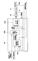
- the master cylinder pressure control unit 25 includes a target hydraulic pressure calculation unit 25A, a control switching unit 25B, and a motor control unit 25C.
- the master cylinder pressure control unit 25 calculates the service target hydraulic pressure by the target hydraulic pressure calculation unit 25A based on the pedal operation amount (displacement amount, pedaling force, etc.) detected by the brake operation amount detection device 24.
- the characteristic of the master cylinder pressure hydroaulic pressure generated with respect to the amount of brake fluid (fluid quantity) that the master cylinder 6 flows downstream by the input piston 12 and the primary piston 6A is referred to as “fluid quantity hydraulic pressure characteristic”. To do.
- the liquid volume / pressure characteristics vary depending on factors such as calipers, rotors, piping, outside air temperature, liquid temperature, and empirical pressure. Therefore, if the characteristic of the service target hydraulic pressure with respect to the pedal operation amount is constant, the movement amount of the primary piston 6A with respect to the pedal operation amount also changes in accordance with the change in the hydraulic fluid pressure characteristic.
- the target hydraulic pressure calculation unit 25A uses a “preliminary nominal hydraulic fluid pressure characteristic map” and “the brake in which the master cylinder 6 is actually caused to flow downstream by the input piston 12 and the primary piston 6A”.
- the service target that can be realized by offsetting the service target hydraulic pressure with respect to the pedal operation amount on the basis of the hydraulic pressure difference based on the hydraulic pressure difference The hydraulic pressure is calculated.
- the target hydraulic pressure calculation unit 25A calculates a service target hydraulic pressure by offsetting a preset hydraulic pressure target value 51 based on the hydraulic pressure difference (hydraulic pressure offset value) as shown in FIG. .
- this hydraulic pressure offset value (hydraulic pressure characteristic value ⁇ P) is used as the hydraulic fluid offset value. It converts into (liquid quantity characteristic value (DELTA) Q), and correct
- the service target hydraulic pressure calculated by the target hydraulic pressure calculation unit 25A is input to the control switching unit 25B.
- the service target hydraulic pressure calculated as described above and the automatic brake target hydraulic pressure received from the vehicle ECU 46 through the CAN communication are selected, for example, by Select High and set as the target hydraulic pressure.
- the target hydraulic pressure is output to the motor control unit 25C.
- the motor control unit 25C calculates the target motor position from the difference between the target hydraulic pressure and the master cylinder pressure, and performs feedback control using the motor position measured by the rotation angle detection sensor 17, whereby the master cylinder pressure To control.
- the master cylinder pressure control unit 25 sets the target hydraulic pressure corresponding to the braking command (the pedal operation amount detected by the brake operation amount detection device 24, the automatic brake command output from the vehicle ECU 46) by the master cylinder 6.
- the drive of the electric motor 16 is controlled so as to occur.
- the master pressure control mechanism 11 While the master pressure control mechanism 11 is operating normally, the master cylinder pressure can be controlled as described above. However, when an abnormality occurs in the master pressure control mechanism 11 and the boost control cannot be performed, the wheel cylinder pressure control mechanism 31 performs the boost as a backup.
- the wheel cylinder pressure control unit 44 includes a target fluid amount calculation unit 44A, a subtraction unit 44B, a motor target rotation number calculation unit 44C, a motor discharge fluid amount calculation unit 44D, and a master cylinder discharge fluid amount calculation unit 44E. Part 44F.
- the wheel cylinder pressure control unit 44 converts the target fluid pressure into the target fluid amount at the target fluid amount calculation unit 44A.
- the target fluid pressure calculating unit 44A receives the target fluid pressure output from the control switching unit 25B of the master cylinder pressure control unit 25.
- the target hydraulic pressure may be transmitted from the master cylinder pressure control unit 25, but may not be transmitted when an abnormality occurs in the master cylinder pressure control unit 25.
- the wheel cylinder pressure control unit 44 directly measures the signal of the brake operation amount detection device 24 to calculate the target hydraulic pressure.
- the vehicle ECU 46 directly measures the signal of the brake operation amount detection device 24 and transmits it to the wheel cylinder pressure control unit 44 by CAN communication (vehicle data bus 45).
- the target fluid pressure is input to the target fluid amount calculation unit 44A of the wheel cylinder pressure control unit 44 when an abnormality occurs in the wheel cylinder pressure control mechanism 31 or the like.
- the target fluid amount calculation unit 44A converts the target fluid pressure into the target fluid amount.
- a wheel cylinder pressure characteristic (fluid fluid pressure characteristic) generated with respect to the brake fluid discharge amount by the wheel cylinder pressure control mechanism 31 is previously mapped (for example, It is set as the liquid volume / pressure characteristic map 61) of FIGS. That is, the target fluid amount calculation unit 44A calculates the target fluid amount from the target fluid pressure using a preset map (fluid fluid-pressure characteristic map 61).
- the target liquid amount calculated by the target liquid amount calculation unit 44A is subtracted from an estimated liquid amount described later by the subtraction unit 44B.
- the difference between the target liquid amount calculated by the subtracting unit 44B and the estimated liquid amount is input to the motor target rotation number calculating unit 44C.
- the motor target rotation number calculation unit 44C calculates the motor target rotation number necessary to realize this liquid amount difference, and drives the motor (pump motor 38). To do.
- wheel cylinder pressure is generated in the wheel cylinders 3FL, 3RR, 3FR, 3RL in accordance with the brake fluid discharge amount based on the drive of the motor (pump motor 38).
- the motor discharge fluid amount calculation unit 44D is a motor that is the amount of brake fluid discharged in accordance with the rotation of the motor (pump motor 38) based on the motor target rotation number calculated by the motor target rotation number calculation unit 44C.
- the amount of discharged liquid is calculated.
- the wheel cylinders 3FL, 3RR, 3FR, 3RL is all the amount discharged by the motor (pump motor 38)
- the wheel cylinders 3FL, 3RR The amount of liquid flowing through 3FR and 3RL can be estimated.
- the master cylinder discharge fluid amount calculation unit 44E calculates the master cylinder discharge fluid amount that is the amount of fluid that the master cylinder 6 has discharged based on the master cylinder pressure immediately before the occurrence of an abnormality in the master pressure control mechanism 11. To do. Then, the master cylinder discharge liquid amount calculated by the master cylinder discharge liquid amount calculation unit 44E and the motor discharge liquid amount calculated by the motor discharge liquid amount calculation unit 44D are added by the addition unit 44F. The value calculated by the adding unit 44F, that is, the value obtained by adding the motor discharge liquid amount to the master discharge liquid amount is set as the estimated liquid amount. The estimated liquid amount is input from the adding unit 44F to the subtracting unit 44B.
- the wheel cylinder pressure control mechanism 31 can perform boost control as a backup.
- the characteristics of the wheel cylinder pressure include calipers, rotors, piping, outside air temperature, fluid temperature, experience pressure, etc.
- variations may occur due to the above factors, that is, disturbance factors.
- the wheel cylinder pressure control unit 31 controls the wheel cylinder pressure by the wheel cylinder pressure control unit 44 as described above, it is based on a preset hydraulic fluid pressure characteristic map (fluid hydraulic pressure characteristic map 61).
- the wheel cylinder pressure is controlled in a feed-forward manner. For this reason, for example, as shown in FIG. 5, when the target hydraulic pressure 2.7 MPa is to be generated, the wheel cylinder pressure control unit 44 follows the preset hydraulic fluid pressure characteristic map 61 and outputs the motor discharge liquid. The motor (pump motor 38) is controlled so that the amount becomes 4cc.
- the liquid volume hydraulic pressure characteristic changes between the maximum liquid volume hydraulic characteristic 66 and the minimum liquid volume hydraulic characteristic 67 as shown in FIG. For this reason, the generated wheel cylinder pressure also changes between 0.8 MPa and 3.0 MPa, and the desired wheel cylinder pressure may not be obtained.
- the target liquid amount is corrected so as to eliminate the variation when the liquid amount / liquid pressure characteristic varies.
- a liquid volume hydraulic pressure characteristic map (liquid volume hydraulic pressure characteristic map 61) when converting the target liquid pressure into the target liquid volume is used as an actual liquid volume liquid value by using a liquid volume characteristic value ⁇ Q described later.
- the target hydraulic pressure calculation unit 25A of the master cylinder pressure control unit 25 shown in FIG. 3 the “nominal hydraulic fluid pressure characteristics” and the “actual hydraulic fluid pressure” used to calculate the service target hydraulic pressure are used.
- the hydraulic pressure difference (hydraulic pressure offset value) from the “hydraulic pressure characteristic” is set as the hydraulic pressure characteristic value ⁇ P, and the hydraulic pressure characteristic value ⁇ Q is calculated by converting the hydraulic pressure characteristic value ⁇ P using a hydraulic pressure / liquid quantity conversion coefficient Z described later. That is, the target hydraulic pressure calculation unit 25A calculates the hydraulic quantity characteristic value ⁇ Q by converting the hydraulic pressure characteristic value ⁇ P corresponding to the hydraulic pressure offset value of FIG.
- a hydraulic pressure liquid quantity conversion coefficient Z shown in FIG. 6 is used for the conversion of the hydraulic pressure characteristic value ⁇ P to the liquid quantity characteristic value ⁇ Q.
- the hydraulic pressure difference X and the hydraulic volume difference Y are calculated using the maximum hydraulic fluid pressure characteristic and the minimum hydraulic fluid pressure characteristic, and the ratio between these is calculated as the hydraulic fluid volume conversion coefficient.
- Z the hydraulic pressure / liquid quantity conversion coefficient Z is defined as X, where the hydraulic pressure difference between the maximum hydraulic fluid pressure characteristic and the minimum hydraulic fluid pressure characteristic is X, and the maximum hydraulic fluid pressure characteristic and the minimum hydraulic fluid pressure characteristic.
- the target hydraulic pressure calculation unit 25A calculates the hydraulic pressure characteristic value ⁇ Q by multiplying the hydraulic pressure characteristic value ⁇ P by the hydraulic pressure hydraulic quantity conversion coefficient Z. That is, the liquid quantity characteristic value ⁇ Q is obtained from the hydraulic pressure characteristic value ⁇ P and the hydraulic pressure liquid quantity conversion coefficient Z by the following equation (2).
- the target fluid pressure calculation unit 25A outputs the fluid amount characteristic value ⁇ Q to the target fluid amount calculation unit 44A of the wheel cylinder pressure control unit 44.
- the target liquid amount calculation unit 44A uses the liquid amount characteristic value ⁇ Q to correct the preset liquid amount / hydraulic pressure characteristic map 61 in the liquid amount axis direction as shown in FIG. A target fluid amount corresponding to the fluid volume characteristic is calculated. That is, the fluid volume / pressure characteristic map 61 is corrected to the corrected fluid volume / pressure characteristic map 62 using the fluid volume characteristic value ⁇ Q, and the target fluid pressure is determined based on the corrected fluid volume / pressure characteristic map 62. Convert to quantity.
- the wheel cylinder pressure control unit 44 controls the motor (pump motor 38) of the wheel cylinder pressure control mechanism 31 using the corrected target liquid amount in the same manner as before the correction.
- the control accuracy of the wheel cylinder pressure can be improved by changing the discharge liquid amount with respect to the same target hydraulic pressure. That is, before correction (when the hydraulic fluid pressure characteristic map 61 is used), the actual wheel cylinder pressure (W / C pressure) deviates from the target hydraulic pressure, whereas after correction (corrected hydraulic fluid). In the case of using the pressure characteristic map 62), it is possible to suppress the deviation of the wheel cylinder pressure (W / C pressure) with respect to the target hydraulic pressure.
- the master cylinder pressure control unit 25 uses the hydraulic pressure characteristic value ⁇ P (hydraulic pressure offset value) used by the target hydraulic pressure calculation unit 25A as the hydraulic pressure characteristic value ⁇ Q ( Convert to liquid volume offset value).
- the master cylinder pressure control unit 25 transmits (outputs) the fluid quantity characteristic value ⁇ Q to the wheel cylinder pressure control unit 44.
- the transmission (output) of the fluid quantity characteristic value ⁇ Q may be performed at all times, may be performed every time the brake is operated, may be performed periodically after a predetermined time elapses, or the master pressure It may be performed when an abnormality occurs in the control mechanism 11 (or just before the occurrence).
- the target fluid amount calculation unit 44A of the wheel cylinder pressure control unit 44 corrects the fluid amount / pressure characteristic map 61 in the fluid amount axis direction using the fluid amount characteristic value ⁇ Q (liquid amount offset value). Then, the wheel cylinder pressure control unit 44 controls the wheel cylinder pressure control mechanism 31 (pump motor 38) using the corrected hydraulic fluid pressure characteristic map (corrected hydraulic fluid pressure characteristic map 62).
- the master cylinder pressure control unit 25 as a hydraulic pressure control circuit includes a memory 25D serving as a storage circuit.
- the memory 25D can be configured by, for example, a flash memory, a ROM, a RAM, an EEPROM, or the like.
- the memory 25 ⁇ / b> D includes an EEPROM that is a nonvolatile storage device (memory) that can maintain memory even when power is not supplied.
- the memory 25D stores a liquid volume characteristic that is a liquid volume characteristic with respect to a detection value of the master cylinder pressure sensor 43A as a hydraulic pressure detector.
- a nominal hydraulic fluid pressure characteristic (for example, the hydraulic pressure target value in FIG. 10) used for calculating the service target hydraulic pressure by the target hydraulic pressure calculator 25A. 51) is stored in advance, the actual hydraulic fluid pressure characteristic, hydraulic pressure characteristic value ⁇ P, hydraulic fluid quantity conversion coefficient Z, fluid quantity characteristic value ⁇ Q, etc. are stored in an updatable manner.
- the wheel cylinder pressure control unit 44 as a liquid amount control circuit includes a memory 44G as a storage circuit.
- the memory 44G can be configured by, for example, a flash memory, a ROM, a RAM, an EEPROM, or the like.
- the memory 44G includes an EEPROM that is a non-volatile storage device (memory) that can maintain the memory even when power is not supplied.
- the memory 44G stores a liquid amount characteristic that is a characteristic of the liquid amount with respect to the detection value of the master cylinder pressure sensor 43A.
- a liquid volume / pressure characteristic map for example, the liquid volume / hydraulic pressure characteristic map of FIG.
- 61 used for calculation of the target liquid volume by the target liquid volume calculation unit 44A. 61) is stored in advance, and the fluid quantity characteristic value ⁇ Q transmitted (output) from the master cylinder pressure control unit 25 (target hydraulic pressure calculation unit 25A) is stored in an updatable manner.
- the wheel cylinder pressure control unit 44 is more specifically corrected by the liquid amount characteristic (liquid amount characteristic value ⁇ Q) based on the liquid amount characteristic (liquid amount characteristic value ⁇ Q) stored in the memory 44G.
- the wheel cylinder pressure control mechanism 31 as the liquid amount supply device is controlled based on the liquid amount / pressure characteristic (corrected liquid amount / hydraulic pressure characteristic map 62).
- the wheel cylinder pressure control unit 44 stores (updatable) a liquid quantity characteristic (liquid quantity characteristic value ⁇ Q) which is a characteristic of the liquid quantity with respect to the hydraulic pressure of the master cylinder 6, and this liquid quantity characteristic (ie, liquid quantity characteristic)
- ⁇ Q liquid quantity characteristic
- the amount of liquid supplied to the wheel cylinders 3FL, 3RR, 3FR, 3RL is controlled on the basis of the corrected hydraulic fluid pressure characteristic map 62) corrected by the amount characteristic value ⁇ Q.
- the wheel cylinder pressure control unit 44 for example, the liquid stored in the memory 44G when the hydraulic pressure for the braking command (automatic brake command, pedal operation amount) cannot be generated by the electric motor 16 of the master pressure control mechanism 11.
- the wheel cylinder pressure control mechanism 31 is controlled based on the quantity characteristic (the liquid quantity / pressure characteristic corrected by the liquid quantity characteristic value ⁇ Q). That is, the wheel cylinder pressure control unit 44, when the electric motor 16 cannot generate the hydraulic pressure corresponding to the braking command, based on the hydraulic characteristics (corrected hydraulic hydraulic characteristics map 62), the wheel cylinders 3FL, 3RR, 3FR, The amount of liquid supplied to 3RL is controlled.
- the master cylinder pressure control unit 25 stores the fluid quantity characteristic (fluid quantity characteristic value ⁇ Q) (updatable) and drives the wheel cylinder pressure control mechanism 31 with the fluid quantity characteristic (fluid quantity characteristic value ⁇ Q). This is transmitted to the wheel cylinder pressure control unit 44 to be controlled.
- the master cylinder pressure control unit 25 determines the fluid amount characteristic (fluid amount characteristic) when the hydraulic pressure with respect to the braking command (automatic brake command, pedal operation amount) cannot be generated by the electric motor 16 of the master pressure control mechanism 11.
- the value ⁇ Q) is transmitted to the wheel cylinder pressure control unit 44.
- the wheel cylinder pressure control unit 44 stores the liquid quantity characteristic (liquid quantity characteristic value ⁇ Q) in the memory 44G.
- the liquid amount characteristic at the previous activation of the wheel cylinder pressure control unit 44 (or the master cylinder pressure control unit 25) is stored in the nonvolatile memory as the liquid amount characteristic (liquid amount characteristic value ⁇ Q). That is, in the memory 44G which is an EEPROM (non-volatile memory), the fluid amount characteristic (fluid amount characteristic value ⁇ Q) at the previous activation of the wheel cylinder pressure control unit 44, for example, calculated at the end during the previous activation. The latest liquid quantity characteristic (liquid quantity characteristic value ⁇ Q) is stored.
- the wheel cylinder pressure control unit 44 allows the liquid quantity characteristic (liquid quantity characteristic value ⁇ Q) stored in the non-volatile memory (memory 44G) immediately after startup, that is, the latest liquid quantity characteristic (liquid quantity characteristic value ⁇ Q).
- the control can be performed by using the corrected fluid quantity fluid pressure characteristic map 62).
- the liquid quantity characteristic (liquid quantity characteristic value ⁇ Q) may be stored in the memory 44G on the wheel cylinder pressure control unit 44 side, or may be stored in the memory 25D on the master cylinder pressure control unit 25 side, You may memorize
- the target liquid amount is corrected by the liquid amount characteristic value ⁇ Q with respect to the liquid amount / hydraulic pressure characteristic map 61 (FIG. 7).
- the present invention is not limited to this.
- the correction may be performed by directly adding the liquid quantity characteristic value ⁇ Q to the target liquid quantity calculated by the liquid quantity hydraulic pressure characteristic map 61 before correction.
- the hydraulic pressure characteristic value ⁇ P is converted into the hydraulic quantity characteristic value ⁇ Q, and then the hydraulic quantity hydraulic pressure characteristic map 61 (FIG. 7) is corrected.
- the present invention is not limited to this, and for example, as shown in FIG. That is, the hydraulic fluid pressure characteristic map 61 may be corrected to the corrected hydraulic fluid pressure characteristic map 63 using the hydraulic pressure characteristic value ⁇ P.
- the master cylinder pressure control unit 25 is configured to transmit the hydraulic pressure characteristic value ⁇ P to the wheel cylinder pressure control unit 44, and the wheel cylinder pressure control unit 44 transmits from the wheel cylinder pressure control unit 44. It is possible to adopt a configuration in which the hydraulic fluid pressure characteristic map 61 is corrected using the hydraulic pressure characteristic value ⁇ P.
- the interpolation line 64 for example, as shown in the overall view of FIG. 9 (a), it is desirable to interpolate the characteristics of the low pressure region that is lost by offsetting the fluid volume / pressure characteristics map 61 to the hydraulic pressure axis. That is, it is desirable to suppress a decrease in control accuracy by creating the interpolation line 64 that smoothes the connection between the fluid pressure characteristics in the low pressure region so as to eliminate a sudden change after the fluid pressure rises.
- the interpolation line 64 for example, as shown in the enlarged view of FIG. 9B, the hydraulic pressure rising point of the predetermined hydraulic fluid pressure characteristic map 61 is set as a point A, and corrected by the hydraulic pressure characteristic value ⁇ P.
- the hydraulic pressure rising point of the corrected hydraulic fluid pressure characteristic map 63 is the point A ′
- the intersection of the reference hydraulic pressure 1.0 MPa and the corrected hydraulic fluid pressure characteristic map 63 is the reference point B
- An intermediate point of ′ is a point C
- an intermediate point of a line segment formed by the reference point B and the intermediate point C is a point D.
- a line segment 64A formed by the hydraulic pressure rising point A and the intermediate point D and a line segment 64B formed by the intermediate point D and the reference point B are set as the interpolation line 64.
- the target hydraulic volume is not calculated using the corrected hydraulic hydraulic pressure characteristic map 63 but the above-described interpolation line 64 (line segment 64A, segment 64B). Is calculated.
- the wheel cylinder pressure control unit 44 is corrected by the liquid amount characteristic (liquid amount characteristic value ⁇ Q) that is the characteristic of the liquid amount with respect to the detection value of the master cylinder pressure sensor 43A.
- the wheel cylinder pressure control mechanism 31 is controlled based on the corrected hydraulic fluid pressure characteristic map 62, the corrected hydraulic fluid pressure characteristic map 63 corrected by the hydraulic pressure characteristic value ⁇ P, and the interpolation line 64). For this reason, the wheel cylinder pressure control unit 44 takes into account this change even if the fluid volume / hydraulic pressure characteristics change with changes in caliper, rotor, piping, outside air temperature, liquid temperature, experience pressure, etc.
- the pressure control mechanism 31 can be controlled.
- the control accuracy of the wheel cylinder pressure by the wheel cylinder pressure control mechanism 31 can be improved.
- the discharge fluid amount (target fluid amount) with the fluid amount characteristic value ⁇ Q, the estimated fluid pressure calculation accuracy in the normal fluid pressure region (for example, a fluid pressure region of 1.0 MPa or less) is ensured. It becomes possible.
- the master cylinder pressure sensor 43A can be the one provided originally. For this reason, the control accuracy of the wheel cylinder pressure can be improved without adding a hydraulic pressure sensor (for example, a wheel cylinder pressure sensor) separately. Thereby, in addition to suppressing an increase in cost, the electric brake system including the automatic brake can be made redundant.
- the master cylinder pressure control unit 25 calculates the fluid quantity characteristic value ⁇ Q (or the hydraulic pressure characteristic value ⁇ P). For this reason, the liquid quantity characteristic value ⁇ Q (or the hydraulic pressure characteristic value ⁇ P) can be calculated in a normal brake operation without operating the wheel cylinder pressure control mechanism 31 that is an ESC (liquid quantity supply device). .
- the wheel cylinder pressure control unit 44 is configured such that when the electric motor 16 of the electric booster 10 cannot generate the hydraulic pressure for the braking command (automatic brake command, pedal operation amount), the master cylinder pressure
- the wheel cylinder pressure control mechanism 31 is controlled.
- the control mechanism 31 can be controlled. Thereby, the backup control by the wheel cylinder pressure control mechanism 31, that is, the wheel cylinder pressure control by the wheel cylinder pressure control mechanism 31 can be accurately performed.
- the wheel cylinder pressure control unit 44 takes into account the change in the hydraulic fluid pressure characteristics not only when the hydraulic pressure cannot be generated by the electric booster 10, but also when the hydraulic pressure can be generated by the electric booster 10.
- the wheel cylinder pressure control mechanism 31 can be controlled.
- the corrected liquid amount liquid corrected by the liquid amount characteristic value ⁇ Q ( The pressure characteristic map 62) or the hydraulic pressure characteristic value ⁇ P (the corrected hydraulic fluid pressure characteristic map 63 and the interpolation line 64) may be used.
- the control accuracy of the wheel cylinder pressure by driving the wheel cylinder pressure control mechanism 31 can be improved regardless of whether the electric booster 10 is normal or malfunctioning.
- the wheel cylinder pressure control unit 44 uses the liquid quantity characteristic (liquid quantity characteristic value ⁇ Q or hydraulic pressure characteristic value ⁇ P) stored in the nonvolatile memory (memory 44G) immediately after startup. Can do. For this reason, even when the electric booster 10 is out of order immediately after startup, the backup control by the wheel cylinder pressure control mechanism 31 can be accurately performed.
- the memory circuit for storing the fluid quantity characteristic value ⁇ Q (or the hydraulic pressure characteristic value ⁇ P) in the first embodiment uses either the memory 25D or 44G of the master cylinder pressure control unit 25 or the wheel cylinder pressure control unit 44. It doesn't matter. However, for example, when the master cylinder pressure control unit 25 fails or when communication between the master cylinder pressure control unit 25 and the wheel cylinder pressure control unit 44 becomes impossible as a system, the wheel cylinder pressure control unit 44 is There is a possibility that the quantity characteristic value ⁇ Q (or the hydraulic pressure characteristic value ⁇ P) cannot be received. For this reason, it is desirable to store the fluid quantity characteristic value ⁇ Q (or the hydraulic pressure characteristic value ⁇ P) in the storage circuit (memory 44G) of the wheel cylinder pressure control unit 44.
- the master cylinder pressure control unit 25 is configured to calculate the fluid quantity characteristic value ⁇ Q (or the hydraulic pressure characteristic value ⁇ P) has been described as an example.
- the wheel cylinder pressure control unit 44 may be input with a “signal or liquid amount for calculating a fluid amount such as a pedal operation amount” and a “master cylinder pressure”, thereby providing a wheel cylinder pressure control unit 44.
- the pressure control unit 44 calculates the fluid quantity characteristic value ⁇ Q and the corrected fluid quantity fluid pressure characteristic map 62 (or the fluid pressure characteristic value ⁇ P and the corrected fluid quantity fluid pressure characteristic map 63 and the interpolation line 64). It is good also as a structure. With such a configuration, independent correction processing can be performed by the wheel cylinder pressure control unit 44 without being influenced by the master cylinder pressure control unit 25.
- FIG. 11 to FIG. 15 show a second embodiment.
- a feature of the second embodiment resides in that a liquid volume / hydraulic pressure characteristic calculating unit for calculating the liquid volume / hydraulic pressure characteristic is provided separately from the liquid pressure control circuit.
- the same components as those in the first embodiment are denoted by the same reference numerals, and the description thereof is omitted.
- the wheel cylinder pressure control unit is based on the fluid quantity characteristic value ⁇ Q calculated from the hydraulic pressure characteristic value ⁇ P originally calculated by the master cylinder pressure control unit 25 (the target hydraulic pressure calculation unit 25A).
- the target liquid amount was corrected by the 44 target liquid amount calculation unit 44A.
- the hydraulic quantity hydraulic pressure characteristic calculation for calculating the hydraulic quantity characteristic value ⁇ Q is provided separately from the target hydraulic pressure calculation unit 25A of the master cylinder pressure control unit 25, the hydraulic quantity hydraulic pressure characteristic calculation for calculating the hydraulic quantity characteristic value ⁇ Q.
- a portion 71 is provided separately from the target hydraulic pressure calculation unit 25A of the master cylinder pressure control unit 25, the hydraulic quantity hydraulic pressure characteristic calculation for calculating the hydraulic quantity characteristic value ⁇ Q.
- the fluid volume / hydraulic pressure characteristic calculation unit 71 is, for example, in the master cylinder pressure control unit 25, in the wheel cylinder pressure control unit 44, or in an ECU different from these units 25 and 44 (for example, in the vehicle ECU 46, It can be configured to be provided in an ECU dedicated to calculating the quantity characteristic value ⁇ Q.
- the master cylinder pressure ( ⁇ ) detected by the master cylinder pressure sensor 43A is input, and the difference between the liquid amount Q2 and the liquid amount Q1 is set as the liquid amount characteristic value ⁇ Q. .
- the liquid amount Q2 is calculated from the detected values of the brake operation amount detection device 24 and the rotation angle detection sensor 17 corresponding to the displacement amount of the input rod 13 and the primary piston 6A when the master cylinder pressure is ⁇ . It is.
- the liquid volume Q1 is a liquid volume calculated using a preset nominal liquid volume hydraulic pressure characteristic map 72 when the master cylinder pressure is ⁇ .
- the target fluid pressure is calculated based on the corrected fluid amount fluid pressure characteristic map 62 corrected by the fluid amount characteristic value ⁇ Q, as in the first embodiment. Is calculated (the target fluid pressure is converted into the target fluid amount).
- FIG. 13 to FIG. 15 show a processing flow performed by the liquid quantity / hydraulic pressure characteristic calculation unit 71.
- the processing flow of FIG. 13 is executed (started) every time the input rod 13 or the primary piston 6A is operated by a brake pedal operation or a braking command by automatic braking in order to calculate the fluid quantity characteristic value ⁇ Q.
- a liquid quantity characteristic value (liquid quantity characteristic storage value) that has been adopted in the past and saved in a storage circuit (for example, a memory of the liquid quantity / hydraulic pressure characteristic calculation unit 71).
- a storage circuit for example, a memory of the liquid quantity / hydraulic pressure characteristic calculation unit 71.
- the liquid quantity characteristic stored value for example, the liquid quantity characteristic adopted value adopted by the liquid quantity / pressure characteristic calculating unit 71 at the time of the previous boost operation is stored in the storage circuit and used.
- the liquid quantity characteristic adopted value that was used last when the master cylinder pressure control unit 25 was last activated is stored in the storage circuit and used.
- the subsequent S2 it is determined whether or not the liquid quantity characteristic value has been calculated after the master cylinder pressure control unit 25 is started. If “NO” in S2, that is, if the actual hydraulic fluid pressure characteristic has not been recognized once after the activation of the master cylinder pressure control unit 25, the process proceeds to S3. In S ⁇ b> 3, the liquid quantity characteristic value is calculated by the liquid quantity / hydraulic pressure characteristic calculation unit 71. Here, when the boost operation is completed during the process of S3, that is, during the calculation of the liquid characteristic value, the subsequent process is not performed.
- a characteristic on the side where the brake characteristic after correction is enhanced is adopted.
- a value that lowers the brake characteristics may be selected, and the selection method is not limited. If the maximum value is adopted in S6, the process returns to the start via the end.
- the large difference process in S7 is a process for determining whether or not the liquid characteristic calculation value calculated in S3 is usable.
- the large difference process at S7 will be described with reference to FIG. FIG. 14 is a control flow of the large difference process in S7.
- the liquid characteristic calculation value calculated in S3 is stored in the storage circuit. Note that the stored value stored in S21 is different from the stored value read in S1, and holds a past value for a predetermined number of times.
- the hydraulic pressure characteristic calculated value calculated in S3 cannot be used, that is, the calculated value cannot be used. If the calculated value cannot be used in S23, the process proceeds to S8 in FIG. 13 via the end.
- S24 it is determined whether or not the number of times that the process of S7 has been continuously performed has reached a predetermined number. If “NO” is determined in S24, as in the case where “NO” is determined in S22, since the certainty of the calculated value cannot be determined yet, the process proceeds to S23. That is, in S23, it is determined that the liquid quantity characteristic calculated value in S3 cannot be used (the calculated value cannot be used), and the process proceeds to S8 in FIG. 13 via the end.
- S24 If “YES” is determined in S24, the process proceeds to S25.
- S25 it is determined whether or not the variation of the past liquid quantity characteristic calculation value for the predetermined number of times stored in S21 is within a predetermined range. If “YES” in S25, that is, if it is determined that the variation in the past liquid amount characteristic calculation values for the predetermined number of times is within the predetermined range, it can be determined that the liquid amount characteristic calculation values in S3 are correctly calculated. In this case, the process proceeds to S26, and it is assumed that the liquid quantity characteristic calculation value obtained in S3 can be used. If the calculated value can be used in S26, the process proceeds to S8 in FIG. 13 via the end.
- FIG. 15 is a control flow of the determination process of whether or not the liquid volume / pressure characteristic of S10 has changed.
- the liquid characteristic comparison value is read.
- the fluid quantity characteristic comparison value for example, the characteristic of the quantity of fluid delivered from the master cylinder 6 during the previous boost operation and the generated brake fluid pressure is used.
- the hydraulic pressure is generated by operating the electric motor 16 regardless of the operation of the brake pedal 9 while the vehicle is stopped, and the characteristics of the amount of fluid delivered from the master cylinder 6 and the generated brake fluid pressure are acquired.
- the liquid characteristic comparison value may be used.
- a temporary storage value stored in the storage circuit in a process to be described later is read.
- the liquid quantity characteristic comparison value read in S31 and the temporary storage value read in S32 are compared to determine whether or not the liquid quantity hydraulic pressure characteristic has changed.
- the liquid pressure generated when the predetermined liquid volume is sent out from the master cylinder 6 and the predetermined liquid volume as input are corrected.
- a case is used in which the difference in hydraulic pressure calculated using the hydraulic fluid pressure characteristic map is a predetermined value or more.
- S34 the liquid quantity characteristic comparison value read in S31 is stored in the storage circuit as a temporary storage value.
- the temporary storage value saved in S34 is read in S32.
- S35 it is determined that there is a change in the liquid volume / pressure characteristics, and the process proceeds to the end. In this case, the determination result in S10 of FIG. 13 is “YES”, and the process proceeds from S10 to S3.
- the reference liquid quantity characteristic value is set as an initial value.
- the liquid quantity characteristic comparison value read in S31 is used as a temporary storage value, and saved in the storage circuit after the process of S10 is completed. May be.
- step S11 the liquid quantity characteristic adopted value used at the previous boost operation is adopted, and the process returns to the start via the end. If “YES” is determined in S10, the same processing as that in the case where “NO” is determined in S2 is performed. As a result, when the hydraulic fluid pressure characteristic has changed since the start of the master cylinder pressure control unit 25, the fluid quantity characteristic value is recalculated. In addition, when the amount of liquid necessary for realizing the target hydraulic pressure cannot be generated at the next boost operation, it is determined that the liquid characteristic value has not been calculated, and “NO” at S2 at the next boost operation. In step S3, the hydraulic pressure characteristic value is calculated.
- the liquid quantity characteristic value ⁇ Q is calculated according to the control flow of FIGS. 13 to 15 as described above, and the basic operation is not particularly different from that in the first embodiment. . That is, also in the second embodiment, as in the first embodiment, the wheel cylinder pressure control unit 44 has a liquid amount characteristic (that is, a liquid amount characteristic) that is a liquid amount characteristic with respect to a detection value of the master cylinder pressure sensor 43A.
- the wheel cylinder pressure control mechanism 31 is controlled based on the corrected hydraulic fluid pressure characteristic map 62) corrected by the value ⁇ Q. For this reason, the control accuracy of the wheel cylinder pressure by the wheel cylinder pressure control mechanism 31 can be improved.
- the liquid quantity characteristic value is calculated at the time of boosting operation.
- the present invention is not limited to this.
- the liquid quantity characteristic value is changed only when the liquid quantity / hydraulic pressure characteristic is changed by performing the process of S10 after S1 without performing the process of S1. It is good also as a structure which calculates. Moreover, it is good also as a structure which calculates a liquid quantity characteristic value by calibrating (calibration) at the time of factory shipment.
- the present invention is not limited to this.
- the hydraulic fluid pressure characteristics (The corrected fluid volume hydraulic characteristic map 62, the corrected fluid volume hydraulic characteristic map 63, and the interpolation line 64) may be used.
- the hydraulic pressure characteristic value ⁇ P (and hence correction) described in the first and second embodiments is used.
- a configuration may be used in which the post-liquid quantity hydraulic pressure characteristic map 63 and the interpolation line 64) or the liquid quantity characteristic value ⁇ Q (and thus the corrected liquid quantity-hydraulic pressure characteristic map 62) is used.
- the master cylinder pressure detected by the master cylinder pressure sensor 43A is used in order to calculate the estimated liquid amount in consideration of the liquid amount discharged from the master cylinder 6.
- the master cylinder pressure sensor 43A fails, the amount of liquid discharged from the master cylinder 6 cannot be calculated, and the hydraulic pressure control accuracy is reduced. Therefore, when it is determined that the master cylinder pressure sensor 43A has failed, the calculation is performed using the detected values of the brake operation amount detection device 24 and the rotation angle detection sensor 17 corresponding to the displacement amounts of the input rod 13 and the primary piston 6A.
- the estimated master cylinder pressure is calculated from the fluid volume / pressure characteristic map corrected by the above-described embodiment, using the discharge fluid volume of the master cylinder 6 as an input.
- the wheel cylinder pressure control can be realized without using the master cylinder pressure sensor 43A. That is, when the master cylinder pressure sensor 43A fails, the discharge fluid amount of the master cylinder 6 calculated by the above-described means is used as the master cylinder discharge fluid amount in the control block diagram of the wheel cylinder pressure control unit 44 shown in FIG. By using it, the hydraulic pressure can be controlled without using the master cylinder pressure sensor 43A. It should be noted that the discharge of the master cylinder 6 calculated using the detected values of the brake operation amount detection device 24 and the rotation angle detection sensor 17 corresponding to the displacement amount of the input rod 13 and the primary piston 6A without calculating the estimated master cylinder pressure.
- the liquid amount may be directly used as the master cylinder discharge liquid amount in the control block of FIG.
- the fluid pressure can be estimated from the fluid amount, and the fluid pressure control can be performed without using the master cylinder pressure sensor 43A.
- the master cylinder pressure sensor 43A is connected to the wheel cylinder pressure control unit 44 in the first and second embodiments described above.
- the configuration is not limited thereto, and for example, the master cylinder pressure sensor 43A may be connected to the master cylinder pressure control unit 25. That is, even if the master cylinder pressure sensor 43A is connected to the wheel cylinder pressure control unit 44 and the master cylinder pressure control unit 25 or the wheel cylinder pressure control unit 44 calculates the fluid amount characteristic value ⁇ Q (or the fluid pressure characteristic value ⁇ P).
- the master cylinder pressure sensor 43A is connected to the master cylinder pressure control unit 25, and the fluid quantity characteristic value ⁇ Q (or the fluid pressure characteristic value ⁇ P) is calculated by the master cylinder pressure control unit 25 or the wheel cylinder pressure control unit 44. Also good.
- the master cylinder pressure sensor 43A is configured to detect the hydraulic pressure of the primary port 6F of the master cylinder 6, but may be configured to detect the hydraulic pressure of the secondary port 6G. Further, although one master cylinder pressure sensor 43A is provided, for example, a configuration in which a plurality (two) of the master cylinder pressure sensor 43A is provided, for example, a configuration in which both the fluid pressure of the primary port 6F and the fluid pressure of the secondary port 6G are detected. Good.
- the electric motor 16 is driven in response to a braking command (braking request) by operating the brake pedal 9 to cause the vehicle to generate a deceleration as well as a braking command (braking) based on an automatic braking command.
- a braking command braking request
- braking braking command
- the case where the vehicle is configured to generate a deceleration by driving the electric motor 16 is also described as an example.
- the present invention is not limited to this, and for example, a configuration in which deceleration is generated in the vehicle by either one (for example, a configuration in which the automatic brake function is omitted) may be employed.
- the electric motor 16 as the electric actuator is a rotary motor
- the electric actuator may be a direct acting motor (linear motor). That is, various electric actuators can be used as the electric actuator for propelling the piston of the electric booster 10 (master pressure control mechanism 11) (that is, the primary piston 6A of the master cylinder 6).
- the electric actuator may be a direct acting motor (linear motor). That is, various electric actuators can be used as the electric actuator for propelling the piston of the electric booster 10 (master pressure control mechanism 11) (that is, the primary piston 6A of the master cylinder 6).
- each embodiment is an exemplification, and partial replacement or combination of the configurations shown in different embodiments is possible.
- the following modes can be considered as the electric brake system, the fluid pressure control circuit, and the fluid amount control circuit based on the embodiment described above.
- the electric brake system is configured to acquire a detection value from a hydraulic pressure detection unit that detects a hydraulic pressure in the master cylinder and generate a target hydraulic pressure corresponding to a braking command in the master cylinder.
- the hydraulic pressure control circuit for controlling the driving of the electric actuator and the liquid amount supply device disposed between the master cylinder and the wheel cylinder to control the amount of liquid supplied to the wheel cylinder A control circuit; and a storage circuit that stores a liquid amount characteristic that is a characteristic of the liquid amount with respect to the detected value.
- the liquid amount control circuit is configured to store the liquid amount characteristic based on the liquid amount characteristic stored in the storage circuit. Control the volume supply device.
- the liquid amount control circuit controls the liquid amount supply device based on the liquid amount characteristic that is the characteristic of the liquid amount with respect to the detection value of the hydraulic pressure detection unit, so that the caliper, the rotor, the piping, Even if the liquid volume / pressure characteristics change with changes in the outside air temperature, liquid temperature, experience pressure, etc., the liquid volume supply device can be controlled in consideration of this change. Thereby, the control accuracy of the wheel cylinder pressure by the liquid supply device can be improved.
- the control accuracy of the wheel cylinder pressure by the fluid amount supply device can be improved.
- the originally provided hydraulic pressure detection unit can be used. For this reason, the control accuracy of the wheel cylinder pressure can be improved without adding a hydraulic pressure sensor (for example, a wheel cylinder pressure sensor) separately. Thereby, in addition to suppressing an increase in cost, the electric brake system can be made redundant.
- the liquid level control circuit when the liquid level control circuit cannot generate the target hydraulic pressure corresponding to the braking command by the electric actuator, the liquid level is based on the liquid level characteristic. Control the feeding device.
- the liquid quantity control circuit controls the liquid quantity supply device in consideration of the change in the liquid quantity / hydraulic pressure characteristic. be able to. Therefore, even when the electric actuator or the hydraulic pressure control circuit breaks down, the backup control by the liquid quantity supply device, that is, the wheel cylinder pressure by the liquid quantity supply device can be accurately performed.
- the hydraulic pressure control circuit changes the liquid quantity characteristic to the liquid quantity control circuit. To communicate.
- the liquid quantity control circuit is based on the liquid quantity characteristic transmitted from the hydraulic pressure control circuit. To control. For this reason, even when the electric actuator or the hydraulic pressure control circuit fails, the liquid quantity supply device can be controlled in consideration of the change in the liquid quantity / hydraulic pressure characteristics, and the backup control by the liquid quantity supply device can be accurately controlled. It can be carried out.
- the liquid amount characteristic at the previous activation is stored in the nonvolatile memory.
- the liquid quantity control circuit can control the liquid quantity supply device based on the liquid quantity characteristics at the previous startup stored in the nonvolatile memory immediately after startup. For this reason, even when the electric actuator or the hydraulic pressure control circuit has failed immediately after startup, the liquid quantity supply device can be controlled in consideration of the change in the liquid quantity / hydraulic characteristics, and the backup by the liquid quantity supply device is possible. Can be accurately controlled.
- the liquid quantity characteristic is stored in the storage circuit on the hydraulic pressure control circuit side.
- the liquid quantity control circuit can accurately control the wheel cylinder pressure by the liquid quantity supply device based on the liquid quantity characteristics stored in the storage circuit on the hydraulic pressure control circuit side. it can.
- the liquid quantity characteristic is stored in the storage circuit on the liquid quantity control circuit side.
- the liquid amount control circuit can accurately control the wheel cylinder pressure by the liquid amount supply device based on the liquid amount characteristic stored in the storage circuit on the liquid amount control circuit side. it can.
- the electric actuator is driven so that a target hydraulic pressure corresponding to a braking command is generated in the master cylinder by obtaining a detection value from a hydraulic pressure detector that detects the hydraulic pressure in the master cylinder.
- a fluid pressure control circuit for controlling, a fluid volume characteristic that is a fluid volume characteristic with respect to the detected value, and storing the fluid volume characteristic between the master cylinder and the wheel cylinder This is transmitted to the liquid level control circuit to be driven.
- the liquid quantity control circuit can control the liquid quantity supply device based on the liquid quantity characteristic transmitted from the hydraulic pressure control circuit.
- the liquid quantity control circuit since the liquid quantity characteristic is the characteristic of the liquid quantity with respect to the detection value of the hydraulic pressure detection unit, the liquid quantity control circuit is accompanied by changes in calipers, rotors, piping, outside air temperature, liquid temperature, empirical pressure, etc. Even if the liquid pressure characteristic changes, the liquid supply device can be controlled in consideration of this change. Thereby, the control accuracy of the wheel cylinder pressure by the liquid supply device can be improved.
- a liquid amount control circuit for controlling the amount of liquid supplied to the wheel cylinder by driving a liquid amount supply device disposed between the master cylinder and the wheel cylinder.
- a liquid quantity characteristic which is a characteristic of the liquid quantity with respect to the hydraulic pressure is stored, and the liquid quantity supplied to the wheel cylinder is controlled based on the liquid quantity characteristic.
- the liquid amount supply device can be controlled based on the stored liquid amount characteristics, the caliper, the rotor, the piping, the outside air temperature, the liquid temperature, the empirical pressure, and the like are changed. Even if the liquid pressure characteristic changes, the liquid supply device can be controlled in consideration of this change. Thereby, the control accuracy of the wheel cylinder pressure by the liquid supply device can be improved.
- the target hydraulic pressure corresponding to the braking command cannot be generated by the electric actuator whose drive is controlled so as to generate the target hydraulic pressure corresponding to the braking command in the master cylinder.
- the amount of liquid supplied to the wheel cylinder is controlled based on the liquid amount characteristic.
- the liquid supply device when the target hydraulic pressure corresponding to the braking command cannot be generated by the electric actuator, the liquid supply device can be controlled in consideration of the change in the hydraulic fluid pressure characteristic. Thereby, even when the electric actuator or the hydraulic pressure control circuit breaks down, the backup control by the liquid quantity supply device, that is, the wheel cylinder pressure by the liquid quantity supply device can be accurately performed.
- 3FL, 3RR, 3FR, 3RL wheel cylinder 5 electric brake control device (electric brake system), 6 master cylinder, 16 electric motor (electric actuator), 25 master cylinder pressure control unit (hydraulic pressure control circuit), 25D memory (memory) Circuit), 31 wheel cylinder pressure control mechanism (fluid supply device), 43A master cylinder pressure sensor (fluid pressure detector), 44 foil cylinder pressure control unit (fluid volume control circuit), 44G memory (memory circuit)
Landscapes
- Engineering & Computer Science (AREA)
- Transportation (AREA)
- Mechanical Engineering (AREA)
- Regulating Braking Force (AREA)
- Braking Systems And Boosters (AREA)
- Valves And Accessory Devices For Braking Systems (AREA)
Abstract
Description


Claims (9)
- 電動ブレーキシステムであって、
マスタシリンダ内の液圧を検出する液圧検出部から検出値を取得して、制動指令に対応する目標液圧を前記マスタシリンダで発生するように電動アクチュエータの駆動を制御する液圧制御回路と、
前記マスタシリンダとホイルシリンダとの間に配置される液量供給装置を駆動して、前記ホイルシリンダへ供給する液量を制御する液量制御回路と、
前記検出値に対する液量の特性である液量特性を記憶する記憶回路と、
を備え、
前記液量制御回路は、前記記憶回路に記憶された前記液量特性に基づいて前記液量供給装置を制御する
電動ブレーキシステム。 - 請求項1において、
前記液量制御回路は、前記制動指令に対応する前記目標液圧を前記電動アクチュエータによって発生できない場合に、前記液量特性に基づいて前記液量供給装置を制御する
電動ブレーキシステム。 - 請求項2において、
前記液圧制御回路は、前記制動指令に対応する前記目標液圧を前記電動アクチュエータによって発生できない場合に、前記液量特性を前記液量制御回路に伝達する
電動ブレーキシステム。 - 請求項1ないし請求項3のいずれかにおいて、
前回の起動時の液量特性が不揮発性メモリに記憶されている
電動ブレーキシステム。 - 請求項1において、
前記液量特性は、前記液圧制御回路側の前記記憶回路で記憶される
電動ブレーキシステム。 - 請求項1において、
前記液量特性は、前記液量制御回路側の前記記憶回路で記憶される
電動ブレーキシステム。 - 液圧制御回路であって、
マスタシリンダ内の液圧を検出する液圧検出部から検出値を取得して、制動指令に対応する目標液圧を前記マスタシリンダで発生するように電動アクチュエータの駆動を制御する液圧制御回路であって、
前記検出値に対する液量の特性である液量特性を記憶し、前記液量特性を前記マスタシリンダとホイルシリンダとの間に配置される液量供給装置を駆動する液量制御回路に伝達する
液圧制御回路。 - マスタシリンダとホイルシリンダとの間に配置される液量供給装置を駆動して、前記ホイルシリンダへ供給する液量を制御する液量制御回路であって、
マスタシリンダの液圧に対する液量の特性である液量特性を記憶し、前記液量特性に基づいてホイルシリンダへ供給する液量を制御する
液量制御回路。 - 請求項8に記載の液量制御回路において、
制動指令に対応する目標液圧をマスタシリンダで発生するように駆動が制御される電動アクチュエータによって前記制動指令に対応する前記目標液圧を発生できない場合に、前記液量特性に基づいてホイルシリンダへ供給する液量を制御する
液量制御回路。
Priority Applications (5)
| Application Number | Priority Date | Filing Date | Title |
|---|---|---|---|
| KR1020207022453A KR20200102509A (ko) | 2018-03-28 | 2019-02-20 | 전동 브레이크 시스템, 액압 제어 회로 및 액량 제어 회로 |
| DE112019001575.3T DE112019001575T5 (de) | 2018-03-28 | 2019-02-20 | Elektrisches Bremssystem, Hydraulikdruckregelkreis, und Fluidmengenregelkreis |
| CN201980022439.5A CN111971216A (zh) | 2018-03-28 | 2019-02-20 | 电动制动系统、液压控制电路以及液量控制电路 |
| US16/981,374 US20210046909A1 (en) | 2018-03-28 | 2019-02-20 | Electric brake system, hydraulic pressure control circuit, and fluid amount control circuit |
| JP2020510424A JPWO2019187807A1 (ja) | 2018-03-28 | 2019-02-20 | 電動ブレーキシステム、液圧制御回路、および、液量制御回路 |
Applications Claiming Priority (2)
| Application Number | Priority Date | Filing Date | Title |
|---|---|---|---|
| JP2018-062129 | 2018-03-28 | ||
| JP2018062129 | 2018-03-28 |
Publications (1)
| Publication Number | Publication Date |
|---|---|
| WO2019187807A1 true WO2019187807A1 (ja) | 2019-10-03 |
Family
ID=68058038
Family Applications (1)
| Application Number | Title | Priority Date | Filing Date |
|---|---|---|---|
| PCT/JP2019/006212 Ceased WO2019187807A1 (ja) | 2018-03-28 | 2019-02-20 | 電動ブレーキシステム、液圧制御回路、および、液量制御回路 |
Country Status (6)
| Country | Link |
|---|---|
| US (1) | US20210046909A1 (ja) |
| JP (1) | JPWO2019187807A1 (ja) |
| KR (1) | KR20200102509A (ja) |
| CN (1) | CN111971216A (ja) |
| DE (1) | DE112019001575T5 (ja) |
| WO (1) | WO2019187807A1 (ja) |
Cited By (5)
| Publication number | Priority date | Publication date | Assignee | Title |
|---|---|---|---|---|
| WO2023120653A1 (ja) * | 2021-12-22 | 2023-06-29 | 株式会社アドヴィックス | 車両の制動制御装置 |
| WO2023120651A1 (ja) * | 2021-12-22 | 2023-06-29 | 株式会社アドヴィックス | 車両の制動制御装置 |
| WO2023120652A1 (ja) * | 2021-12-22 | 2023-06-29 | 株式会社アドヴィックス | 車両の制動制御装置 |
| JP2024547049A (ja) * | 2021-12-23 | 2024-12-26 | ロベルト・ボッシュ・ゲゼルシャフト・ミト・ベシュレンクテル・ハフツング | 液圧ブレーキシステム、ブレーキシステムを運転するための方法、並びに液圧ブレーキシステムを備えた自動車 |
| WO2025110223A1 (ja) * | 2023-11-22 | 2025-05-30 | 株式会社アドヴィックス | 車両の制動制御装置 |
Families Citing this family (7)
| Publication number | Priority date | Publication date | Assignee | Title |
|---|---|---|---|---|
| CN110316174B (zh) * | 2019-08-16 | 2023-08-08 | 吉林大学 | 具有踏板力补偿功能的集成式电动助力制动系统 |
| JP7424165B2 (ja) * | 2020-03-30 | 2024-01-30 | 株式会社アドヴィックス | 車両用制動装置 |
| US11847919B2 (en) * | 2020-05-19 | 2023-12-19 | Toyota Motor North America, Inc. | Control of transport en route |
| CN116917177A (zh) * | 2021-03-23 | 2023-10-20 | 日立安斯泰莫株式会社 | 电动制动器的控制装置、电动制动装置以及电动制动器的控制方法 |
| CN112918454B (zh) * | 2021-03-31 | 2021-12-07 | 东风汽车集团股份有限公司 | 线控制动系统状态的分析方法、系统及存储介质 |
| DE102022129424A1 (de) * | 2022-11-08 | 2024-05-08 | Audi Aktiengesellschaft | Verfahren zum Steuern eines Bremssystems, Bremssystem sowie Kraftfahrzeug |
| US20240359674A1 (en) * | 2023-04-25 | 2024-10-31 | ZF Active Safety US Inc. | Brake system apparatuses, methods, and arrangements |
Citations (3)
| Publication number | Priority date | Publication date | Assignee | Title |
|---|---|---|---|---|
| JP2009040290A (ja) * | 2007-08-10 | 2009-02-26 | Hitachi Ltd | ブレーキ制御装置 |
| JP2013147182A (ja) * | 2012-01-20 | 2013-08-01 | Toyota Motor Corp | 車両制御装置 |
| JP2014097687A (ja) * | 2012-11-13 | 2014-05-29 | Hitachi Automotive Systems Ltd | ブレーキ制御装置 |
Family Cites Families (2)
| Publication number | Priority date | Publication date | Assignee | Title |
|---|---|---|---|---|
| JP5014919B2 (ja) | 2007-08-17 | 2012-08-29 | 日立オートモティブシステムズ株式会社 | ブレーキ制御装置 |
| JP6409189B2 (ja) | 2015-03-31 | 2018-10-24 | 日立オートモティブシステムズ株式会社 | ブレーキ制御装置 |
-
2019
- 2019-02-20 JP JP2020510424A patent/JPWO2019187807A1/ja not_active Ceased
- 2019-02-20 CN CN201980022439.5A patent/CN111971216A/zh active Pending
- 2019-02-20 WO PCT/JP2019/006212 patent/WO2019187807A1/ja not_active Ceased
- 2019-02-20 KR KR1020207022453A patent/KR20200102509A/ko not_active Withdrawn
- 2019-02-20 DE DE112019001575.3T patent/DE112019001575T5/de not_active Ceased
- 2019-02-20 US US16/981,374 patent/US20210046909A1/en not_active Abandoned
Patent Citations (3)
| Publication number | Priority date | Publication date | Assignee | Title |
|---|---|---|---|---|
| JP2009040290A (ja) * | 2007-08-10 | 2009-02-26 | Hitachi Ltd | ブレーキ制御装置 |
| JP2013147182A (ja) * | 2012-01-20 | 2013-08-01 | Toyota Motor Corp | 車両制御装置 |
| JP2014097687A (ja) * | 2012-11-13 | 2014-05-29 | Hitachi Automotive Systems Ltd | ブレーキ制御装置 |
Cited By (10)
| Publication number | Priority date | Publication date | Assignee | Title |
|---|---|---|---|---|
| WO2023120653A1 (ja) * | 2021-12-22 | 2023-06-29 | 株式会社アドヴィックス | 車両の制動制御装置 |
| WO2023120651A1 (ja) * | 2021-12-22 | 2023-06-29 | 株式会社アドヴィックス | 車両の制動制御装置 |
| WO2023120652A1 (ja) * | 2021-12-22 | 2023-06-29 | 株式会社アドヴィックス | 車両の制動制御装置 |
| JP2023093195A (ja) * | 2021-12-22 | 2023-07-04 | 株式会社アドヴィックス | 車両の制動制御装置 |
| JP2023093197A (ja) * | 2021-12-22 | 2023-07-04 | 株式会社アドヴィックス | 車両の制動制御装置 |
| JP2023093196A (ja) * | 2021-12-22 | 2023-07-04 | 株式会社アドヴィックス | 車両の制動制御装置 |
| JP7715035B2 (ja) | 2021-12-22 | 2025-07-30 | 株式会社アドヴィックス | 車両の制動制御装置 |
| JP7800119B2 (ja) | 2021-12-22 | 2026-01-16 | 株式会社アドヴィックス | 車両の制動制御装置 |
| JP2024547049A (ja) * | 2021-12-23 | 2024-12-26 | ロベルト・ボッシュ・ゲゼルシャフト・ミト・ベシュレンクテル・ハフツング | 液圧ブレーキシステム、ブレーキシステムを運転するための方法、並びに液圧ブレーキシステムを備えた自動車 |
| WO2025110223A1 (ja) * | 2023-11-22 | 2025-05-30 | 株式会社アドヴィックス | 車両の制動制御装置 |
Also Published As
| Publication number | Publication date |
|---|---|
| JPWO2019187807A1 (ja) | 2020-12-10 |
| DE112019001575T5 (de) | 2020-12-10 |
| CN111971216A (zh) | 2020-11-20 |
| US20210046909A1 (en) | 2021-02-18 |
| KR20200102509A (ko) | 2020-08-31 |
Similar Documents
| Publication | Publication Date | Title |
|---|---|---|
| WO2019187807A1 (ja) | 電動ブレーキシステム、液圧制御回路、および、液量制御回路 | |
| JP6849822B2 (ja) | 電動倍力装置およびブレーキ制御装置 | |
| KR102134063B1 (ko) | 브레이크 제어 장치 | |
| JP6335387B2 (ja) | ブレーキ制御装置および制御方法 | |
| US10023166B2 (en) | Brake control device | |
| US9981642B2 (en) | Electric brake system and method thereof | |
| US20090045672A1 (en) | Brake control apparatus and method | |
| CN108349482B (zh) | 用于液压车辆制动系统的泵组 | |
| CN107107890A (zh) | 尤其用于交通工具制动器的操纵系统和用于运行操纵系统的方法 | |
| KR20140109277A (ko) | 브레이크 제어 장치 | |
| JP4661621B2 (ja) | 車両用ブレーキ制御装置 | |
| US11117561B2 (en) | Sensor monitoring device and braking control device for vehicle provided with sensor monitoring device | |
| CN111699118A (zh) | 用于自动驾驶的陆上运输工具的电液式外力-车辆制动设备 | |
| CN108725415A (zh) | 电子制动系统及其控制方法 | |
| JP6033645B2 (ja) | ブレーキ装置 | |
| US12344212B2 (en) | Braking control device for vehicle | |
| JP6221118B2 (ja) | ブレーキシステム | |
| JP5775290B2 (ja) | ブレーキ制御装置 | |
| JP6409189B2 (ja) | ブレーキ制御装置 | |
| JP4696949B2 (ja) | 車両用ブレーキ制御装置 | |
| WO2018139529A1 (ja) | 電動ブレーキ装置 | |
| JP2020132050A (ja) | ブレーキシステム |
Legal Events
| Date | Code | Title | Description |
|---|---|---|---|
| 121 | Ep: the epo has been informed by wipo that ep was designated in this application |
Ref document number: 19776569 Country of ref document: EP Kind code of ref document: A1 |
|
| ENP | Entry into the national phase |
Ref document number: 2020510424 Country of ref document: JP Kind code of ref document: A |
|
| ENP | Entry into the national phase |
Ref document number: 20207022453 Country of ref document: KR Kind code of ref document: A |
|
| 122 | Ep: pct application non-entry in european phase |
Ref document number: 19776569 Country of ref document: EP Kind code of ref document: A1 |