WO2019187455A1 - 画像処理装置、画像表示システム、画像処理方法、及び、プログラム - Google Patents
画像処理装置、画像表示システム、画像処理方法、及び、プログラム Download PDFInfo
- Publication number
- WO2019187455A1 WO2019187455A1 PCT/JP2018/048477 JP2018048477W WO2019187455A1 WO 2019187455 A1 WO2019187455 A1 WO 2019187455A1 JP 2018048477 W JP2018048477 W JP 2018048477W WO 2019187455 A1 WO2019187455 A1 WO 2019187455A1
- Authority
- WO
- WIPO (PCT)
- Prior art keywords
- image
- ambient light
- image data
- generating
- light information
- Prior art date
- Legal status (The legal status is an assumption and is not a legal conclusion. Google has not performed a legal analysis and makes no representation as to the accuracy of the status listed.)
- Ceased
Links
Images


Classifications
-
- H—ELECTRICITY
- H04—ELECTRIC COMMUNICATION TECHNIQUE
- H04N—PICTORIAL COMMUNICATION, e.g. TELEVISION
- H04N1/00—Scanning, transmission or reproduction of documents or the like, e.g. facsimile transmission; Details thereof
- H04N1/00835—Detecting external or ambient light
-
- G—PHYSICS
- G03—PHOTOGRAPHY; CINEMATOGRAPHY; ANALOGOUS TECHNIQUES USING WAVES OTHER THAN OPTICAL WAVES; ELECTROGRAPHY; HOLOGRAPHY
- G03B—APPARATUS OR ARRANGEMENTS FOR TAKING PHOTOGRAPHS OR FOR PROJECTING OR VIEWING THEM; APPARATUS OR ARRANGEMENTS EMPLOYING ANALOGOUS TECHNIQUES USING WAVES OTHER THAN OPTICAL WAVES; ACCESSORIES THEREFOR
- G03B21/00—Projectors or projection-type viewers; Accessories therefor
- G03B21/134—Projectors combined with typing apparatus or with printing apparatus
-
- G—PHYSICS
- G06—COMPUTING OR CALCULATING; COUNTING
- G06T—IMAGE DATA PROCESSING OR GENERATION, IN GENERAL
- G06T1/00—General purpose image data processing
-
- G—PHYSICS
- G09—EDUCATION; CRYPTOGRAPHY; DISPLAY; ADVERTISING; SEALS
- G09G—ARRANGEMENTS OR CIRCUITS FOR CONTROL OF INDICATING DEVICES USING STATIC MEANS TO PRESENT VARIABLE INFORMATION
- G09G3/00—Control arrangements or circuits, of interest only in connection with visual indicators other than cathode-ray tubes
- G09G3/001—Control arrangements or circuits, of interest only in connection with visual indicators other than cathode-ray tubes using specific devices not provided for in groups G09G3/02 - G09G3/36, e.g. using an intermediate record carrier such as a film slide; Projection systems; Display of non-alphanumerical information, solely or in combination with alphanumerical information, e.g. digital display on projected diapositive as background
- G09G3/002—Control arrangements or circuits, of interest only in connection with visual indicators other than cathode-ray tubes using specific devices not provided for in groups G09G3/02 - G09G3/36, e.g. using an intermediate record carrier such as a film slide; Projection systems; Display of non-alphanumerical information, solely or in combination with alphanumerical information, e.g. digital display on projected diapositive as background to project the image of a two-dimensional display, such as an array of light emitting or modulating elements or a CRT
-
- G—PHYSICS
- G09—EDUCATION; CRYPTOGRAPHY; DISPLAY; ADVERTISING; SEALS
- G09G—ARRANGEMENTS OR CIRCUITS FOR CONTROL OF INDICATING DEVICES USING STATIC MEANS TO PRESENT VARIABLE INFORMATION
- G09G5/00—Control arrangements or circuits for visual indicators common to cathode-ray tube indicators and other visual indicators
- G09G5/02—Control arrangements or circuits for visual indicators common to cathode-ray tube indicators and other visual indicators characterised by the way in which colour is displayed
- G09G5/06—Control arrangements or circuits for visual indicators common to cathode-ray tube indicators and other visual indicators characterised by the way in which colour is displayed using colour palettes, e.g. look-up tables
-
- G—PHYSICS
- G09—EDUCATION; CRYPTOGRAPHY; DISPLAY; ADVERTISING; SEALS
- G09G—ARRANGEMENTS OR CIRCUITS FOR CONTROL OF INDICATING DEVICES USING STATIC MEANS TO PRESENT VARIABLE INFORMATION
- G09G5/00—Control arrangements or circuits for visual indicators common to cathode-ray tube indicators and other visual indicators
- G09G5/36—Control arrangements or circuits for visual indicators common to cathode-ray tube indicators and other visual indicators characterised by the display of a graphic pattern, e.g. using an all-points-addressable [APA] memory
- G09G5/37—Details of the operation on graphic patterns
- G09G5/377—Details of the operation on graphic patterns for mixing or overlaying two or more graphic patterns
-
- H—ELECTRICITY
- H04—ELECTRIC COMMUNICATION TECHNIQUE
- H04N—PICTORIAL COMMUNICATION, e.g. TELEVISION
- H04N1/00—Scanning, transmission or reproduction of documents or the like, e.g. facsimile transmission; Details thereof
- H04N1/46—Colour picture communication systems
- H04N1/56—Processing of colour picture signals
- H04N1/60—Colour correction or control
- H04N1/603—Colour correction or control controlled by characteristics of the picture signal generator or the picture reproducer
- H04N1/6052—Matching two or more picture signal generators or two or more picture reproducers
-
- H—ELECTRICITY
- H04—ELECTRIC COMMUNICATION TECHNIQUE
- H04N—PICTORIAL COMMUNICATION, e.g. TELEVISION
- H04N1/00—Scanning, transmission or reproduction of documents or the like, e.g. facsimile transmission; Details thereof
- H04N1/46—Colour picture communication systems
- H04N1/56—Processing of colour picture signals
- H04N1/60—Colour correction or control
- H04N1/6083—Colour correction or control controlled by factors external to the apparatus
- H04N1/6086—Colour correction or control controlled by factors external to the apparatus by scene illuminant, i.e. conditions at the time of picture capture, e.g. flash, optical filter used, evening, cloud, daylight, artificial lighting, white point measurement, colour temperature
-
- H—ELECTRICITY
- H04—ELECTRIC COMMUNICATION TECHNIQUE
- H04N—PICTORIAL COMMUNICATION, e.g. TELEVISION
- H04N9/00—Details of colour television systems
- H04N9/12—Picture reproducers
- H04N9/31—Projection devices for colour picture display, e.g. using electronic spatial light modulators [ESLM]
- H04N9/3179—Video signal processing therefor
- H04N9/3182—Colour adjustment, e.g. white balance, shading or gamut
-
- H—ELECTRICITY
- H04—ELECTRIC COMMUNICATION TECHNIQUE
- H04N—PICTORIAL COMMUNICATION, e.g. TELEVISION
- H04N9/00—Details of colour television systems
- H04N9/12—Picture reproducers
- H04N9/31—Projection devices for colour picture display, e.g. using electronic spatial light modulators [ESLM]
- H04N9/3191—Testing thereof
- H04N9/3194—Testing thereof including sensor feedback
-
- G—PHYSICS
- G09—EDUCATION; CRYPTOGRAPHY; DISPLAY; ADVERTISING; SEALS
- G09G—ARRANGEMENTS OR CIRCUITS FOR CONTROL OF INDICATING DEVICES USING STATIC MEANS TO PRESENT VARIABLE INFORMATION
- G09G2360/00—Aspects of the architecture of display systems
- G09G2360/14—Detecting light within display terminals, e.g. using a single or a plurality of photosensors
- G09G2360/144—Detecting light within display terminals, e.g. using a single or a plurality of photosensors the light being ambient light
Definitions
- the present invention relates to a technique for displaying an image using a printer and a projector.
- HDR image high dynamic range image
- Patent Document 1 discloses that an input image is expressed with a wider dynamic range or color gamut by superimposing a print image by a printer and a projection image by a projector. Specifically, a signal decomposition LUT (lookup table) generated based on the spectral distribution characteristic in the projector and the spectral reflectance characteristic in the printer is used to convert the input image into an image signal for the projector and an image for the printer. Convert to signal. Then, the images formed by the projector and the printer are superimposed on the basis of the converted image signal. Further, Patent Document 1 discloses that the color of an input image is faithfully reproduced in consideration of the influence of a light source (hereinafter also referred to as ambient light) in an image observation environment when creating a signal decomposition LUT. Yes.
- a light source hereinafter also referred to as ambient light
- an object of the present invention is to more faithfully reproduce the color of an input image under different ambient light without preparing a different signal decomposition LUT for each ambient light.
- An image processing apparatus generates data for generating a superimposed image by superimposing an image formed by an image forming apparatus and an image projected by an image projection apparatus.
- the image processing apparatus generates, based on input image data, first image data corresponding to the image forming apparatus and second image data corresponding to the image projection apparatus, and the superimposing First acquisition means for acquiring ambient light information related to ambient light when an image is generated, and correction means for correcting the second image data based on the ambient light information; It is characterized by providing.
- the color of the input image can be reproduced more faithfully under different ambient light.
- an image projection apparatus acquires ambient light (that is, ambient light information) using a spectroscopic sensor, and the projection image compensates for a color variation that a change in the ambient light gives to the superimposed color.
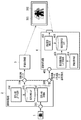
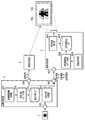
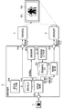
- FIG. 1 is a block diagram showing a configuration of an image display system in the present embodiment.
- 1 is an input image
- 2 is an image processing apparatus (PC)
- 3 is an image forming apparatus (printer)
- 4 is an image projection apparatus (projector).
- the image display system superimposes the projection image 502 projected by the image projection device 4 on the print image 501 formed on the recording medium by the image forming device 3, thereby reducing the dynamic range and color gamut of the input image 1.
- a superimposed image that is reproduced more faithfully can be displayed.
- the image forming apparatus 3 will be described as an ink jet printer, and the image projecting apparatus 4 will be described as a liquid crystal projector.
- the image processing apparatus 2 can be implemented by, for example, a printer driver installed in a general personal computer. In that case, each part of the image processing apparatus 2 described below is realized by the CPU of the computer executing a program stored in a predetermined memory or storage device. As another configuration, for example, the image processing device 2 may include one or both of the image forming device 3 and the image projection device 4.
- the image processing apparatus 2 receives input image data from the image data input terminal 201.
- the input image data is sent to the signal decomposition processing unit 202.
- tristimulus values Xt, Yt, and Zt that are reproduction targets of each pixel of the superimposed image are input as input image data.
- the input image data is not limited to the above, and, for example, an RGB 8-bit 3-channel color image may be input as the input image.
- the image processing apparatus 2 includes a color conversion processing unit (not shown), and performs conversion processing from RGB to CIEXYZ (XYZ color space defined by CIE (International Lighting Commission)) for each pixel of the input image. Do. By doing so, the image processing apparatus 2 acquires the tristimulus values Xt, Yt, and Zt that are the reproduction target of the superimposed image.
- the signal decomposition processing unit 202 generates print image data to be sent to the image forming apparatus 3 and projection image data to be sent to the image projection apparatus 4 from the tristimulus values Xt, Yt and Zt (that is, input image data). To do. At this time, the signal decomposition processing unit 202 performs signal decomposition processing (that is, image data generation processing) with reference to the signal decomposition LUT (lookup table) 203.
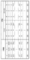
- FIG. 2 shows an example of the signal decomposition LUT 203 in the present embodiment.
- the signal decomposition LUT 203 stores a combination of printer RGB and projector RGB corresponding to each lattice point of the tristimulus values XYZ. These combinations are created in advance so that the tristimulus values of the lattice points and the tristimulus values of the superimposed image are equal.
- the signal decomposition LUT 203 is created by the signal decomposition LUT creation unit 206. Details of the signal decomposition LUT creation processing will be described later.
- the print image data calculated by the signal decomposition processing unit 202 is sent from the output terminal 204 to the image forming apparatus 3.
- the image forming apparatus 3 forms a print image 501 using the acquired print image data.
- both the projection image data and the print image data are sent from the output terminal 205 to the image projection apparatus 4.
- Information on the reference ambient light is also sent out.
- the reference ambient light is ambient light used when calculating XYZ of the superimposed color in the creation of the signal decomposition LUT 203. Details will be described later.
- the image projection device 4 receives projection image data, print image data, and reference ambient light information from the input terminal 401.
- the projection image data is corrected by the projection image correction unit 402. That is, the projection image correction unit 402 functions as a projection image data correction unit. At this time, the projection image correction unit 402 corrects the projection image data with reference to the projection image correction LUT 403.
- the projection image correction LUT 403 is an LUT in which printer RGB, projector RGB, and superimposition color XYZ are stored, as in the signal decomposition LUT 203.
- the input / output relationship is different. That is, the signal decomposition LUT 203 is an XYZ-RGBRGB LUT in which XYZ is input and printer RGB and projector RGB are output.
- the projection image correction LUT 403 is an RGBXYZ-RGB LUT in which printers RGB and XYZ are input and projector RGB is an output.
- the projection image correction LUT 403 is created by the projection image correction LUT creation unit 405. Details of creating the projection image correction LUT will be described later.
- the ambient light acquisition unit 404 acquires ambient light information of the environment where the superimposed image is displayed.
- the acquired ambient light information is sent to the projection image correction LUT creation unit 405.
- the projection image correction LUT creation unit 405 creates the projection image correction LUT 403 when the ambient light is different from the reference ambient light.
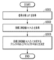
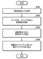
- step S ⁇ b> 301 the signal decomposition processing unit 202 acquires the signal decomposition LUT 203.
- the signal decomposition processing unit 202 acquires tristimulus values Xt, Yt, Zt (that is, input image data) that are reproduction targets from the image data input terminal 201.
- the tristimulus values Xt, Yt, Zt of the reproduction target of the entire image may be acquired and expanded in a memory (not shown), or the acquisition and processing may be repeated for each pixel. Good.
- step S303 the signal decomposition processing unit 202 uses the signal decomposition LUT described above to perform a projector for each pixel from the target tristimulus values Xt, Yt, Zt of each pixel by a known conversion method such as interpolation processing. RGB values and printer RGB values are calculated.
- the projector RGB value and the printer RGB value of each pixel are calculated from the projector RGB value and the printer RGB value stored in the signal decomposition LUT 203 by a known tetrahedral interpolation process.
- the printer RGB value and the projector RGB value for reproducing the reproduction target tristimulus values Xt, Yt, Zt as a superimposed image can be calculated by the processing of S301 to S303 described above.
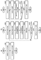
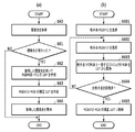
- the signal decomposition LUT creation unit 206 first creates an RGBRGB-XYZ LUT (S40). This LUT takes printer RGB and projector RGB as inputs, and outputs XYZ of superimposed colors. Details of S40 will be described later.
- the signal decomposition LUT creation unit 206 generates an XYZ-RGBRGB signal decomposition LUT 203 by reversely performing the RGBRGB-XYZ LUT by interpolation processing (S41). Details of S41 will be described later.
- FIG. 4B is a flowchart of the RGBRGB-XYZ LUT creation process (S40).
- the signal decomposition LUT creation unit 206 generates RGBRGB lattice signals. For example, RGB grid values that are equally spaced by 5 grids for each color are generated for each of printer RGB and projector RGB. In this case, the number of lattice signals is 15625 which is the sixth power of 5 grids.
- the signal decomposition LUT creation unit 206 acquires one RGBRGB value corresponding to one grid point in the grid signal generated in S401.
- the signal decomposition LUT creation unit 206 acquires the spectral distribution characteristics of the image projection device 4 corresponding to the projector RGB values acquired in S402.
- the spectral distribution characteristics of the image projection device 4 are obtained by measuring the spectral distribution with respect to predetermined RGB values in advance, and are stored as a spectral distribution profile. If the spectral distribution profile does not include an RGB value that matches the target RGB value, the spectral distribution characteristic for the target RGB value is calculated by interpolation processing or the like.
- the signal decomposition LUT creation unit 206 acquires the spectral reflectance characteristics of the image forming apparatus 3 corresponding to the printer RGB values acquired in S402.
- the spectral reflectance characteristics of the image forming apparatus 3 are obtained in advance by measuring a patch printed on a target medium based on predetermined RGB values, and are stored as, for example, a spectral reflectance profile. If the spectral reflectance profile does not include an RGB value that matches the target RGB value, a spectral reflectance characteristic for the target RGB value is calculated by interpolation processing or the like.
- step S ⁇ b> 405 the signal decomposition LUT creation unit 206 calculates an XYZ value that is a superimposed color when the projection color based on the projector RGB value acquired in step S ⁇ b> 402 and the print color based on the printer RGB value are superimposed on each other as follows. Calculated by equation (1).
- rgb1 and rgb2 are projector RGB and printer RGB, respectively, and X (rgb1, rgb2), Y (rgb1, rgb2), and Z (rgb1, rgb2) are superimpositions corresponding to combinations of these RGB. This is the XYZ value of the color.
- ⁇ represents a wavelength
- Sprj (rgb1, ⁇ ) is a spectral distribution of projected light with respect to rgb1
- Rprn (rgb2, ⁇ ) is a spectral reflectance of the printed material with respect to rgb2.
- Sill ( ⁇ ) is a spectral distribution of ambient light
- x ( ⁇ ), y ( ⁇ ), and z ( ⁇ ) are XYZ color matching functions with a double field of view. That is, the light obtained by adding the spectral distribution of the projection light and the spectral distribution of the ambient light is irradiated onto the printed matter and reflected as a product of the spectral reflectance of the image forming apparatus becomes the spectral distribution of the superimposed color.
- the XYZ value of the superimposition color is obtained by weighting this with an XYZ color matching function and then integrating it.
- the spectral distribution of the CIE daylight D50 is used as the ambient light Sill ( ⁇ ).
- the ambient light Sill ( ⁇ ) is not limited.
- the spectral distribution of the environmental light displaying the superimposed image can be acquired and estimated, it is desirable to use the spectral distribution.
- the signal decomposition LUT creation unit 206 determines whether or not the XYZ values for all the lattice signals generated in S401 have been calculated. If all have been calculated, the process proceeds to S407. If not, the process returns to S402, and processing is performed on a lattice signal for which an XYZ value has not yet been calculated.
- the signal decomposition LUT creation unit 206 creates an RGBRGB-XYZ LUT by associating the RGBRGB signal generated in S401 with the XYZ signal calculated in S405.
- FIG. 4C is a flowchart of the XYZ-RGBRGB LUT creation process (S41).
- step S408 the signal decomposition LUT creation unit 206 generates an XYZ lattice signal.
- XYZ values that are evenly distributed within the XYZ reproducible range calculated in S405 are generated.
- the signal decomposition LUT creation unit 206 acquires an XYZ value of one color corresponding to one grid point in the grid signal generated in S408.
- the signal decomposition LUT creation unit 206 obtains the projector RGB and printer RGB corresponding to the XYZ values obtained in S409 from the RGBRGB-XYZ LUT created in S407. If an XYZ value that matches the target XYZ value is not included, projector RGB and printer RGB for the target XYZ value are calculated by interpolation processing or the like.
- the signal decomposition LUT creation unit 206 determines whether or not the RGBRGB values for all the lattice signals generated in S408 have been calculated. If all have been calculated, the process proceeds to S412. If not, the process returns to S409, and processing is performed on a grid signal for which RGBRGB values have not yet been calculated.
- the signal decomposition LUT creation unit 206 creates the XYZ-RGBRGB signal decomposition LUT 203 by associating the XYZ signal generated in S408 with the RGBRGB signal calculated in S410.
- step S ⁇ b> 501 the projection image correction unit 402 acquires a projection image correction LUT 403.
- step S ⁇ b> 502 the projection image correction unit 402 acquires printer RGB, projector RGB, and reference environment light from the input terminal 401.
- the projection image correction unit 402 calculates the XYZ of the superimposed image in the reference environment light for each pixel.
- the calculation of the superimposed color is the same as the process of S405 in FIG.
- step S504 a projector RGB value for each pixel is calculated from the superimposed image XYZ and the printer RGB using the projection image correction LUT 403.
- the projector RGB can be corrected in accordance with changes in the environmental light (that is, different environmental lights).
- FIG. 6A shows a flowchart of the projection image correction LUT creation process.
- the projection image correction LUT creation unit 405 acquires ambient light from the ambient light acquisition unit 404.
- the projection image correction LUT creation unit 405 determines whether the acquired ambient light has changed from the assumed ambient light.
- the assumed ambient light is the ambient light used when the projection image correction LUT was previously created.
- the assumed environment light is the reference environment light Sill ( ⁇ ), and is replaced with the acquired environment light after the projection image correction LUT creation processing. If it is determined that the acquired ambient light has not changed, it is not necessary to create a projection image correction LUT, and thus the process ends. On the other hand, if it is determined that it has changed, the process proceeds to S62.
- the projection image correction LUT creation unit 405 creates an RGBRGB-XYZ LUT. Since this process is the same as the process of S40 in FIG. However, in S62, the projection image correction LUT creation unit 405 calculates XYZ using the environmental light acquired from the environmental light acquisition unit 404 instead of the reference environmental light Sill ( ⁇ ) in the superimposed color calculation of S405.
- the projection image correction LUT creation unit 405 creates an RGBXYZ-RGB projection image correction LUT.
- This LUT receives printer RGB and superimposed colors XYZ and outputs projector RGB.
- FIG. 6B is a flowchart showing details of the process in S63.
- step S601 the projection image correction LUT creation unit 405 generates RGBXYZ lattice signals.
- values that are equally spaced in 5 grids for each color are generated for each of XYZ and printer RGB.
- the number of lattice signals is 15625 which is the sixth power of 5 grids.
- the projection image correction LUT creation unit 405 acquires one RGBXYZ value corresponding to one grid point of the grid signal generated in S601.
- step S603 the projection image correction LUT creation unit 405 acquires the projector RGB corresponding to the RGBXYZ value acquired in step S602. At this time, with reference to the RGBRGB-XYZ LUT created in S62, if the RGBXYZ value that matches the target RGBXYZ value is not included, the projector RGB for the target RGBXYZ value is acquired by interpolation processing or the like.
- the projection image correction LUT creation unit 405 determines whether or not the projector RGB values have been calculated for all the lattice signals. If all have been calculated, the process proceeds to S605. If not, the process returns to S602 to perform processing on the grid signal for which the projector RGB values have not yet been calculated.
- step S605 the projection image correction LUT creation unit 405 creates an RGBXYZ-RGB projection image correction LUT 403 by associating the RGBXYZ signal generated in step S601 with the projector RGB signal calculated in step S603.
- the projection image correction LUT creation unit 405 holds the acquired ambient light.
- the ambient light held here is the assumed ambient light in S61 described above, and is referred to when the projection image correction LUT 403 is created again.
- the ambient light is acquired using the spectroscopic sensor, and the influence of the change in the ambient light on the superimposed color is compensated by the projected image, thereby further improving the color of the input image. Can be faithfully reproduced.
- the input to the image projection apparatus 4 is a three-channel projector RGB
- the type of signal is not limited.
- the image projection device 4 is a multiband projector capable of spectral reproduction
- spectral signal values of three or more channels are input.
- the projection image correction process shown in FIG. 5 can directly compensate for the difference in ambient light change, so that the printer RGB acquisition (S502) and the superimposed color calculation process (S503) are essential. is not.
- step S503 of the projection image correction process shown in FIG. 5 the superimposed color with the reference ambient light is calculated using the equation (1).
- the method for calculating the superimposed color is not limited.
- the RGBRGB-XYZ LUT created in S40 may be used.
- the spectroscopic sensor is more expensive than a general color sensor and causes an increase in apparatus cost.
- an RGB color sensor may be used instead of the spectroscopic sensor, and the spectral distribution of the ambient light may be estimated.
- the spectral distribution of the ambient light is estimated from the RGB values of the acquired ambient light by creating and holding in advance a table that associates the RGB color sensor values and the spectral distributions in a plurality of known ambient lights. it can. Of course, you may hold
- the example in which the projection image correction process is performed when it is determined whether the ambient light has changed from the assumed ambient light and it is determined that the ambient light has changed has been described.
- the execution timing is arbitrary. It is. For example, a configuration in which the user instructs execution is possible.
- FIG. 7A shows a flowchart of the projection image correction LUT creation process in the projection image correction LUT creation unit 405.
- FIG. 7B is a flowchart of the process for creating the XYZ-RGB projected image correction LUT in S73.
- the projection image correction LUT creation unit 405 generates an XYZ lattice signal. For example, the value which becomes a uniform space
- the projection image correction LUT creation unit 405 acquires an XYZ value of one color corresponding to one grid point in the grid signal generated in S701.
- the projection image correction LUT creation unit 405 acquires the projector RGB that minimizes the average error from the XYZ values acquired in step S702.
- the average error is obtained by obtaining the XYZ when a certain projector RGB is superimposed on a plurality of printers RGB from the RGBRGB-XYZ LUT, calculating the error from the grid points XYZ, and then calculating the error. Averaged.
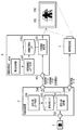
- FIG. 8 is a block diagram showing the configuration of the image display system in the present embodiment.
- the image processing apparatus 2 according to the present embodiment is different from the first embodiment in that the image processing apparatus 2 includes a fluctuation range information acquisition unit 207. Details of the processing by the fluctuation range information acquisition unit 207 will be described later.
- the signal decomposition LUT creation unit 206 in the present embodiment acquires the fluctuation range information and creates the signal decomposition LUT 203. Details of the signal decomposition LUT creation processing will be described later.
- the user first selects “light source selection” to input multiple types of ambient light source, “color temperature specification” to enter the range of ambient light color temperature numerically, and “spectral distribution specification” to specify multiple spectral distribution profiles. Select one with the check box.
- “light source selection” for example, fluorescent lamp, halogen, outdoor (daytime), and the like are displayed.
- the user selects a plurality of assumed light source types.
- “Specify color temperature” is selected, the upper and lower limits of the color temperature are selected by moving the slider bar left and right.
- “Spectral distribution designation” is selected, spectral distribution profile data acquired by a spectral sensor or the like is acquired.
- the user selects a plurality of assumed spectral profiles.
- a corresponding spectral distribution profile is set in advance.
- the plurality of spectral distribution profiles are sent to the signal decomposition LUT creation unit 206 as variation range information.
- the signal decomposition LUT creation unit 206 acquires the fluctuation range information from the fluctuation range information acquisition unit 207. That is, a plurality of ambient light spectral distribution profiles are acquired. Further, the signal decomposition LUT creation unit 206 calculates the average of the spectral distribution profiles, and calculates Smean ( ⁇ ) as the spectral distribution profile of the average ambient light.
- the signal decomposition LUT creation unit 206 calculates the XYZ values of the superimposed colors corresponding to the projector RGB values and printer RGB values acquired in S402 by the following equation (2).
- the XYZ values of the superimposed colors are calculated using the average environmental light Smean ( ⁇ ) as the reference environmental light instead of the environmental light Sill ( ⁇ ) used in the equation (1).
- the correction amount by the projection image correction unit 402 is also small.
- the correction amount by the projection image correction unit 402 may exceed the correction limit.
- the average Ambient light Smean ( ⁇ ) (slightly red, color temperature 5000K) is used as the reference ambient light.
- the printed image 501 formed at this time looks slightly blue when observed in the daytime period without projection light, and appears slightly red in the evening time period. In other words, the difference between the acquired ambient light and the reference ambient light is almost the same in any time zone, but the difference is unlikely to increase. Therefore, the possibility of exceeding the limit of correction by the projection image correction unit 402 can be reduced.
- the printer RGB and the projector RGB are determined using the range in which the ambient light can be changed.
- the color of the input image can be faithfully reproduced.
- Equation (3) the calculation of the superimposed color in S405 can be performed using equation (3) as follows.
- FIG. 10 shows an example of the reference environment light setting UI 1000.
- the user can set the reference ambient light by moving the slider bar shown at the bottom of the reference ambient light setting UI 1000 left and right.
- a preview image is displayed on the upper part of the reference environment light setting UI 1000 in accordance with the movement of the slider bar.
- the preview image is obtained by estimating superimposed images at the upper limit and the lower limit of the fluctuation range information acquired by the fluctuation range information acquisition unit 207.
- any preview image is the same as the input image.
- the correction amount by the projection image correction unit 402 is outside the correctable range, at least one preview image is different from the input image.
- the user can adjust the reference ambient light with the slider bar while judging whether this change is acceptable. Note that only a region where the preview image and the input image are different may be extracted and displayed as an image. That is, the signal decomposition processing unit 202 generates print image data and projection image data so that the correction amount by the projection image correction unit 402 is within a correctable range with respect to a predetermined range of ambient light information.
- FIG. 11 shows the configuration of the image display system in this case.
- a print image correction unit 1101 corrects print image data.
- a print image correction LUT creation unit 1103 creates a print image correction LUT 1002.
- the process of correcting the print image data can be realized by replacing the projection image and the print image in the processes performed by the projection image correction unit 402, the projection image correction LUT 403, and the projection image correction LUT creation unit 405.
- the image projection device 4 includes the projection image correction unit 402.
- the image processing device 2 may include the projection image correction unit 402.
- the configuration of the image display system in this case is shown in FIG. As described above, since the color variation may be compensated by the print image, the image processing apparatus 2 may include the print image correction unit 1101.
- the correction LUT is created based on the ambient light information.
- the method for determining the correction LUT is not limited to the above-described example.
- one correction LUT may be selected from a plurality of types of correction LUTs created in advance based on ambient light information.
- the present invention supplies a program that realizes one or more functions of the above-described embodiments to a system or apparatus via a network or a storage medium, and one or more processors in a computer of the system or apparatus read and execute the program
- This process can be realized. It can also be realized by a circuit (for example, ASIC) that realizes one or more functions.
Landscapes
- Engineering & Computer Science (AREA)
- Multimedia (AREA)
- Signal Processing (AREA)
- Physics & Mathematics (AREA)
- General Physics & Mathematics (AREA)
- Theoretical Computer Science (AREA)
- Computer Hardware Design (AREA)
- Image Processing (AREA)
- Color Image Communication Systems (AREA)
- Facsimile Image Signal Circuits (AREA)
- Projection Apparatus (AREA)
- Transforming Electric Information Into Light Information (AREA)
- Controls And Circuits For Display Device (AREA)
Priority Applications (1)
| Application Number | Priority Date | Filing Date | Title |
|---|---|---|---|
| US17/026,899 US11825245B2 (en) | 2018-03-27 | 2020-09-21 | Image processing device, image display system, image processing method, and program |
Applications Claiming Priority (2)
| Application Number | Priority Date | Filing Date | Title |
|---|---|---|---|
| JP2018060107 | 2018-03-27 | ||
| JP2018-060107 | 2018-03-27 |
Related Child Applications (1)
| Application Number | Title | Priority Date | Filing Date |
|---|---|---|---|
| US17/026,899 Continuation US11825245B2 (en) | 2018-03-27 | 2020-09-21 | Image processing device, image display system, image processing method, and program |
Publications (1)
| Publication Number | Publication Date |
|---|---|
| WO2019187455A1 true WO2019187455A1 (ja) | 2019-10-03 |
Family
ID=68059708
Family Applications (1)
| Application Number | Title | Priority Date | Filing Date |
|---|---|---|---|
| PCT/JP2018/048477 Ceased WO2019187455A1 (ja) | 2018-03-27 | 2018-12-28 | 画像処理装置、画像表示システム、画像処理方法、及び、プログラム |
Country Status (3)
| Country | Link |
|---|---|
| US (1) | US11825245B2 (enExample) |
| JP (1) | JP7327957B2 (enExample) |
| WO (1) | WO2019187455A1 (enExample) |
Families Citing this family (3)
| Publication number | Priority date | Publication date | Assignee | Title |
|---|---|---|---|---|
| JP7277231B2 (ja) | 2019-04-15 | 2023-05-18 | キヤノン株式会社 | 画像処理装置、画像処理方法およびプログラム |
| JP7481935B2 (ja) | 2020-07-21 | 2024-05-13 | キヤノン株式会社 | 画像処理装置、画像処理方法 |
| CN113949853B (zh) * | 2021-10-13 | 2022-10-25 | 济南景雄影音科技有限公司 | 具备环境适应调整能力的投影系统 |
Citations (5)
| Publication number | Priority date | Publication date | Assignee | Title |
|---|---|---|---|---|
| JP2000175062A (ja) * | 1998-12-07 | 2000-06-23 | Sony Corp | 画像処理装置及び画像処理方法 |
| JP2008122558A (ja) * | 2006-11-10 | 2008-05-29 | Seiko Epson Corp | 表示装置 |
| JP2008145915A (ja) * | 2006-12-13 | 2008-06-26 | Seiko Epson Corp | 表示装置 |
| JP2010103863A (ja) * | 2008-10-24 | 2010-05-06 | Canon Inc | 画像処理システムおよび画像処理装置、および画像処理方法 |
| JP2017212516A (ja) * | 2016-05-24 | 2017-11-30 | セイコーエプソン株式会社 | プロジェクター及びプロジェクターの制御方法 |
Family Cites Families (9)
| Publication number | Priority date | Publication date | Assignee | Title |
|---|---|---|---|---|
| KR100840102B1 (ko) * | 2007-02-23 | 2008-06-19 | 삼성에스디아이 주식회사 | 유기 전계발광 표시장치 |
| KR101627634B1 (ko) * | 2011-12-26 | 2016-06-08 | 한국전자통신연구원 | 프로젝터 영상 보정 장치 및 방법 |
| JP6516446B2 (ja) | 2014-11-14 | 2019-05-22 | キヤノン株式会社 | 情報処理装置、情報処理方法、及びプログラム |
| US10205854B2 (en) | 2015-01-30 | 2019-02-12 | Canon Kabushiki Kaisha | Image processing apparatus, image processing method, and appearance reproduction apparatus |
| JP6609141B2 (ja) | 2015-08-27 | 2019-11-20 | キヤノン株式会社 | 画像処理装置およびその方法、並びに、画像形成装置 |
| JP6840604B2 (ja) | 2017-04-11 | 2021-03-10 | キヤノン株式会社 | 色変換テーブルの作成装置、色変換テーブルの作成方法、色変換処理装置、色変換処理方法およびプログラム |
| JP6862267B2 (ja) | 2017-05-02 | 2021-04-21 | キヤノン株式会社 | 色変換ルックアップテーブルの作成装置、色変換ルックアップテーブルの作成方法およびプログラム |
| JP6895821B2 (ja) | 2017-06-28 | 2021-06-30 | キヤノン株式会社 | 画像処理装置および画像処理方法 |
| JP7204420B2 (ja) | 2018-10-25 | 2023-01-16 | キヤノン株式会社 | 画像処理装置、及び、画像処理方法 |
-
2018
- 2018-12-28 WO PCT/JP2018/048477 patent/WO2019187455A1/ja not_active Ceased
-
2019
- 2019-03-13 JP JP2019045785A patent/JP7327957B2/ja active Active
-
2020
- 2020-09-21 US US17/026,899 patent/US11825245B2/en active Active
Patent Citations (5)
| Publication number | Priority date | Publication date | Assignee | Title |
|---|---|---|---|---|
| JP2000175062A (ja) * | 1998-12-07 | 2000-06-23 | Sony Corp | 画像処理装置及び画像処理方法 |
| JP2008122558A (ja) * | 2006-11-10 | 2008-05-29 | Seiko Epson Corp | 表示装置 |
| JP2008145915A (ja) * | 2006-12-13 | 2008-06-26 | Seiko Epson Corp | 表示装置 |
| JP2010103863A (ja) * | 2008-10-24 | 2010-05-06 | Canon Inc | 画像処理システムおよび画像処理装置、および画像処理方法 |
| JP2017212516A (ja) * | 2016-05-24 | 2017-11-30 | セイコーエプソン株式会社 | プロジェクター及びプロジェクターの制御方法 |
Also Published As
| Publication number | Publication date |
|---|---|
| US20210006758A1 (en) | 2021-01-07 |
| US11825245B2 (en) | 2023-11-21 |
| JP2019176461A (ja) | 2019-10-10 |
| JP7327957B2 (ja) | 2023-08-16 |
Similar Documents
| Publication | Publication Date | Title |
|---|---|---|
| US8731288B2 (en) | Image processing techniques for color correction | |
| KR20100074016A (ko) | 타깃 컬러 재현 디바이스의 교정 방법 | |
| US6151135A (en) | Method and apparatus for color reproduction | |
| JP2009225424A (ja) | 色補正係数生成装置及びプログラム | |
| JP7327957B2 (ja) | 画像表示システム、方法、及び、プログラム | |
| JP5854034B2 (ja) | 色処理装置、画像形成装置およびプログラム | |
| US8405673B2 (en) | Color processing apparatus and color processing method | |
| US10152945B2 (en) | Image processing apparatus capable of performing conversion on input image data for wide dynamic range | |
| JP2010217645A (ja) | 画像表示装置の補正値作成方法、画像表示装置の補正値作成装置、及び画像表示装置の補正値作成プログラム | |
| US9288456B2 (en) | Image processing apparatus and method | |
| JP2010217644A (ja) | 画像表示装置の補正値作成方法、画像表示装置の補正値作成装置、及び画像表示装置の補正値作成プログラム | |
| JP5025323B2 (ja) | 色処理装置および方法 | |
| JP2007110724A (ja) | 入力色空間をcmyk色空間に変換する方法及び装置 | |
| JP5322326B2 (ja) | 色補正テーブル算出回路、色補正装置、表示装置、色補正方法、及びプログラム | |
| JP2011024202A (ja) | 色変換装置、色変換方法、および画像表示システム | |
| JP6320278B2 (ja) | 色処理装置およびその方法 | |
| JP2010251940A (ja) | 画像処理装置、画像処理方法、およびプログラム | |
| JP2011205467A (ja) | 色処理装置及びプログラム | |
| JP4633806B2 (ja) | 色プロファイルのための色補正テクニック | |
| JP2008172681A (ja) | 色変換装置、色変換方法、色変換プログラム、色変換係数作成装置、色変換係数作成方法、及び色変換係数作成プログラム | |
| JP5748236B2 (ja) | 色補正情報の生成方法、及び色補正装置 | |
| JP4532797B2 (ja) | 画像処理方法及び画像処理装置 | |
| JP4853303B2 (ja) | 色変換装置及びプログラム | |
| JP5306110B2 (ja) | 画像処理装置、画像処理方法、プログラム及び記憶媒体 | |
| KR100555111B1 (ko) | 에스알지비 표준 영상을 매개로 한 디지털 영상 장치 간의색관리 방법 |
Legal Events
| Date | Code | Title | Description |
|---|---|---|---|
| 121 | Ep: the epo has been informed by wipo that ep was designated in this application |
Ref document number: 18912005 Country of ref document: EP Kind code of ref document: A1 |
|
| NENP | Non-entry into the national phase |
Ref country code: DE |
|
| 122 | Ep: pct application non-entry in european phase |
Ref document number: 18912005 Country of ref document: EP Kind code of ref document: A1 |