WO2019187455A1 - Image processing device, image display system, image processing method, and program - Google Patents
Image processing device, image display system, image processing method, and program Download PDFInfo
- Publication number
- WO2019187455A1 WO2019187455A1 PCT/JP2018/048477 JP2018048477W WO2019187455A1 WO 2019187455 A1 WO2019187455 A1 WO 2019187455A1 JP 2018048477 W JP2018048477 W JP 2018048477W WO 2019187455 A1 WO2019187455 A1 WO 2019187455A1
- Authority
- WO
- WIPO (PCT)
- Prior art keywords
- image
- ambient light
- image data
- generating
- light information
- Prior art date
Links
Images


Classifications
-
- H—ELECTRICITY
- H04—ELECTRIC COMMUNICATION TECHNIQUE
- H04N—PICTORIAL COMMUNICATION, e.g. TELEVISION
- H04N1/00—Scanning, transmission or reproduction of documents or the like, e.g. facsimile transmission; Details thereof
- H04N1/00835—Detecting external or ambient light
-
- G—PHYSICS
- G03—PHOTOGRAPHY; CINEMATOGRAPHY; ANALOGOUS TECHNIQUES USING WAVES OTHER THAN OPTICAL WAVES; ELECTROGRAPHY; HOLOGRAPHY
- G03B—APPARATUS OR ARRANGEMENTS FOR TAKING PHOTOGRAPHS OR FOR PROJECTING OR VIEWING THEM; APPARATUS OR ARRANGEMENTS EMPLOYING ANALOGOUS TECHNIQUES USING WAVES OTHER THAN OPTICAL WAVES; ACCESSORIES THEREFOR
- G03B21/00—Projectors or projection-type viewers; Accessories therefor
- G03B21/134—Projectors combined with typing apparatus or with printing apparatus
-
- G—PHYSICS
- G06—COMPUTING; CALCULATING OR COUNTING
- G06T—IMAGE DATA PROCESSING OR GENERATION, IN GENERAL
- G06T1/00—General purpose image data processing
-
- G—PHYSICS
- G09—EDUCATION; CRYPTOGRAPHY; DISPLAY; ADVERTISING; SEALS
- G09G—ARRANGEMENTS OR CIRCUITS FOR CONTROL OF INDICATING DEVICES USING STATIC MEANS TO PRESENT VARIABLE INFORMATION
- G09G3/00—Control arrangements or circuits, of interest only in connection with visual indicators other than cathode-ray tubes
- G09G3/001—Control arrangements or circuits, of interest only in connection with visual indicators other than cathode-ray tubes using specific devices not provided for in groups G09G3/02 - G09G3/36, e.g. using an intermediate record carrier such as a film slide; Projection systems; Display of non-alphanumerical information, solely or in combination with alphanumerical information, e.g. digital display on projected diapositive as background
- G09G3/002—Control arrangements or circuits, of interest only in connection with visual indicators other than cathode-ray tubes using specific devices not provided for in groups G09G3/02 - G09G3/36, e.g. using an intermediate record carrier such as a film slide; Projection systems; Display of non-alphanumerical information, solely or in combination with alphanumerical information, e.g. digital display on projected diapositive as background to project the image of a two-dimensional display, such as an array of light emitting or modulating elements or a CRT
-
- G—PHYSICS
- G09—EDUCATION; CRYPTOGRAPHY; DISPLAY; ADVERTISING; SEALS
- G09G—ARRANGEMENTS OR CIRCUITS FOR CONTROL OF INDICATING DEVICES USING STATIC MEANS TO PRESENT VARIABLE INFORMATION
- G09G5/00—Control arrangements or circuits for visual indicators common to cathode-ray tube indicators and other visual indicators
- G09G5/02—Control arrangements or circuits for visual indicators common to cathode-ray tube indicators and other visual indicators characterised by the way in which colour is displayed
- G09G5/06—Control arrangements or circuits for visual indicators common to cathode-ray tube indicators and other visual indicators characterised by the way in which colour is displayed using colour palettes, e.g. look-up tables
-
- G—PHYSICS
- G09—EDUCATION; CRYPTOGRAPHY; DISPLAY; ADVERTISING; SEALS
- G09G—ARRANGEMENTS OR CIRCUITS FOR CONTROL OF INDICATING DEVICES USING STATIC MEANS TO PRESENT VARIABLE INFORMATION
- G09G5/00—Control arrangements or circuits for visual indicators common to cathode-ray tube indicators and other visual indicators
- G09G5/36—Control arrangements or circuits for visual indicators common to cathode-ray tube indicators and other visual indicators characterised by the display of a graphic pattern, e.g. using an all-points-addressable [APA] memory
- G09G5/37—Details of the operation on graphic patterns
- G09G5/377—Details of the operation on graphic patterns for mixing or overlaying two or more graphic patterns
-
- H—ELECTRICITY
- H04—ELECTRIC COMMUNICATION TECHNIQUE
- H04N—PICTORIAL COMMUNICATION, e.g. TELEVISION
- H04N1/00—Scanning, transmission or reproduction of documents or the like, e.g. facsimile transmission; Details thereof
- H04N1/46—Colour picture communication systems
- H04N1/56—Processing of colour picture signals
- H04N1/60—Colour correction or control
- H04N1/603—Colour correction or control controlled by characteristics of the picture signal generator or the picture reproducer
- H04N1/6052—Matching two or more picture signal generators or two or more picture reproducers
-
- H—ELECTRICITY
- H04—ELECTRIC COMMUNICATION TECHNIQUE
- H04N—PICTORIAL COMMUNICATION, e.g. TELEVISION
- H04N1/00—Scanning, transmission or reproduction of documents or the like, e.g. facsimile transmission; Details thereof
- H04N1/46—Colour picture communication systems
- H04N1/56—Processing of colour picture signals
- H04N1/60—Colour correction or control
- H04N1/6083—Colour correction or control controlled by factors external to the apparatus
- H04N1/6086—Colour correction or control controlled by factors external to the apparatus by scene illuminant, i.e. conditions at the time of picture capture, e.g. flash, optical filter used, evening, cloud, daylight, artificial lighting, white point measurement, colour temperature
-
- H—ELECTRICITY
- H04—ELECTRIC COMMUNICATION TECHNIQUE
- H04N—PICTORIAL COMMUNICATION, e.g. TELEVISION
- H04N9/00—Details of colour television systems
- H04N9/12—Picture reproducers
- H04N9/31—Projection devices for colour picture display, e.g. using electronic spatial light modulators [ESLM]
- H04N9/3179—Video signal processing therefor
- H04N9/3182—Colour adjustment, e.g. white balance, shading or gamut
-
- H—ELECTRICITY
- H04—ELECTRIC COMMUNICATION TECHNIQUE
- H04N—PICTORIAL COMMUNICATION, e.g. TELEVISION
- H04N9/00—Details of colour television systems
- H04N9/12—Picture reproducers
- H04N9/31—Projection devices for colour picture display, e.g. using electronic spatial light modulators [ESLM]
- H04N9/3191—Testing thereof
- H04N9/3194—Testing thereof including sensor feedback
-
- G—PHYSICS
- G09—EDUCATION; CRYPTOGRAPHY; DISPLAY; ADVERTISING; SEALS
- G09G—ARRANGEMENTS OR CIRCUITS FOR CONTROL OF INDICATING DEVICES USING STATIC MEANS TO PRESENT VARIABLE INFORMATION
- G09G2360/00—Aspects of the architecture of display systems
- G09G2360/14—Detecting light within display terminals, e.g. using a single or a plurality of photosensors
- G09G2360/144—Detecting light within display terminals, e.g. using a single or a plurality of photosensors the light being ambient light
Definitions
- the present invention relates to a technique for displaying an image using a printer and a projector.
- HDR image high dynamic range image
- Patent Document 1 discloses that an input image is expressed with a wider dynamic range or color gamut by superimposing a print image by a printer and a projection image by a projector. Specifically, a signal decomposition LUT (lookup table) generated based on the spectral distribution characteristic in the projector and the spectral reflectance characteristic in the printer is used to convert the input image into an image signal for the projector and an image for the printer. Convert to signal. Then, the images formed by the projector and the printer are superimposed on the basis of the converted image signal. Further, Patent Document 1 discloses that the color of an input image is faithfully reproduced in consideration of the influence of a light source (hereinafter also referred to as ambient light) in an image observation environment when creating a signal decomposition LUT. Yes.
- a light source hereinafter also referred to as ambient light
- an object of the present invention is to more faithfully reproduce the color of an input image under different ambient light without preparing a different signal decomposition LUT for each ambient light.
- An image processing apparatus generates data for generating a superimposed image by superimposing an image formed by an image forming apparatus and an image projected by an image projection apparatus.
- the image processing apparatus generates, based on input image data, first image data corresponding to the image forming apparatus and second image data corresponding to the image projection apparatus, and the superimposing First acquisition means for acquiring ambient light information related to ambient light when an image is generated, and correction means for correcting the second image data based on the ambient light information; It is characterized by providing.
- the color of the input image can be reproduced more faithfully under different ambient light.
- an image projection apparatus acquires ambient light (that is, ambient light information) using a spectroscopic sensor, and the projection image compensates for a color variation that a change in the ambient light gives to the superimposed color.
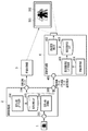
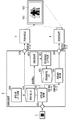
- FIG. 1 is a block diagram showing a configuration of an image display system in the present embodiment.
- 1 is an input image
- 2 is an image processing apparatus (PC)
- 3 is an image forming apparatus (printer)
- 4 is an image projection apparatus (projector).
- the image display system superimposes the projection image 502 projected by the image projection device 4 on the print image 501 formed on the recording medium by the image forming device 3, thereby reducing the dynamic range and color gamut of the input image 1.
- a superimposed image that is reproduced more faithfully can be displayed.
- the image forming apparatus 3 will be described as an ink jet printer, and the image projecting apparatus 4 will be described as a liquid crystal projector.
- the image processing apparatus 2 can be implemented by, for example, a printer driver installed in a general personal computer. In that case, each part of the image processing apparatus 2 described below is realized by the CPU of the computer executing a program stored in a predetermined memory or storage device. As another configuration, for example, the image processing device 2 may include one or both of the image forming device 3 and the image projection device 4.
- the image processing apparatus 2 receives input image data from the image data input terminal 201.
- the input image data is sent to the signal decomposition processing unit 202.
- tristimulus values Xt, Yt, and Zt that are reproduction targets of each pixel of the superimposed image are input as input image data.
- the input image data is not limited to the above, and, for example, an RGB 8-bit 3-channel color image may be input as the input image.
- the image processing apparatus 2 includes a color conversion processing unit (not shown), and performs conversion processing from RGB to CIEXYZ (XYZ color space defined by CIE (International Lighting Commission)) for each pixel of the input image. Do. By doing so, the image processing apparatus 2 acquires the tristimulus values Xt, Yt, and Zt that are the reproduction target of the superimposed image.
- the signal decomposition processing unit 202 generates print image data to be sent to the image forming apparatus 3 and projection image data to be sent to the image projection apparatus 4 from the tristimulus values Xt, Yt and Zt (that is, input image data). To do. At this time, the signal decomposition processing unit 202 performs signal decomposition processing (that is, image data generation processing) with reference to the signal decomposition LUT (lookup table) 203.
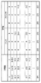
- FIG. 2 shows an example of the signal decomposition LUT 203 in the present embodiment.
- the signal decomposition LUT 203 stores a combination of printer RGB and projector RGB corresponding to each lattice point of the tristimulus values XYZ. These combinations are created in advance so that the tristimulus values of the lattice points and the tristimulus values of the superimposed image are equal.
- the signal decomposition LUT 203 is created by the signal decomposition LUT creation unit 206. Details of the signal decomposition LUT creation processing will be described later.
- the print image data calculated by the signal decomposition processing unit 202 is sent from the output terminal 204 to the image forming apparatus 3.
- the image forming apparatus 3 forms a print image 501 using the acquired print image data.
- both the projection image data and the print image data are sent from the output terminal 205 to the image projection apparatus 4.
- Information on the reference ambient light is also sent out.
- the reference ambient light is ambient light used when calculating XYZ of the superimposed color in the creation of the signal decomposition LUT 203. Details will be described later.
- the image projection device 4 receives projection image data, print image data, and reference ambient light information from the input terminal 401.
- the projection image data is corrected by the projection image correction unit 402. That is, the projection image correction unit 402 functions as a projection image data correction unit. At this time, the projection image correction unit 402 corrects the projection image data with reference to the projection image correction LUT 403.
- the projection image correction LUT 403 is an LUT in which printer RGB, projector RGB, and superimposition color XYZ are stored, as in the signal decomposition LUT 203.
- the input / output relationship is different. That is, the signal decomposition LUT 203 is an XYZ-RGBRGB LUT in which XYZ is input and printer RGB and projector RGB are output.
- the projection image correction LUT 403 is an RGBXYZ-RGB LUT in which printers RGB and XYZ are input and projector RGB is an output.
- the projection image correction LUT 403 is created by the projection image correction LUT creation unit 405. Details of creating the projection image correction LUT will be described later.
- the ambient light acquisition unit 404 acquires ambient light information of the environment where the superimposed image is displayed.
- the acquired ambient light information is sent to the projection image correction LUT creation unit 405.
- the projection image correction LUT creation unit 405 creates the projection image correction LUT 403 when the ambient light is different from the reference ambient light.
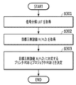
- step S ⁇ b> 301 the signal decomposition processing unit 202 acquires the signal decomposition LUT 203.
- the signal decomposition processing unit 202 acquires tristimulus values Xt, Yt, Zt (that is, input image data) that are reproduction targets from the image data input terminal 201.
- the tristimulus values Xt, Yt, Zt of the reproduction target of the entire image may be acquired and expanded in a memory (not shown), or the acquisition and processing may be repeated for each pixel. Good.
- step S303 the signal decomposition processing unit 202 uses the signal decomposition LUT described above to perform a projector for each pixel from the target tristimulus values Xt, Yt, Zt of each pixel by a known conversion method such as interpolation processing. RGB values and printer RGB values are calculated.
- the projector RGB value and the printer RGB value of each pixel are calculated from the projector RGB value and the printer RGB value stored in the signal decomposition LUT 203 by a known tetrahedral interpolation process.
- the printer RGB value and the projector RGB value for reproducing the reproduction target tristimulus values Xt, Yt, Zt as a superimposed image can be calculated by the processing of S301 to S303 described above.
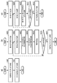
- the signal decomposition LUT creation unit 206 first creates an RGBRGB-XYZ LUT (S40). This LUT takes printer RGB and projector RGB as inputs, and outputs XYZ of superimposed colors. Details of S40 will be described later.
- the signal decomposition LUT creation unit 206 generates an XYZ-RGBRGB signal decomposition LUT 203 by reversely performing the RGBRGB-XYZ LUT by interpolation processing (S41). Details of S41 will be described later.
- FIG. 4B is a flowchart of the RGBRGB-XYZ LUT creation process (S40).
- the signal decomposition LUT creation unit 206 generates RGBRGB lattice signals. For example, RGB grid values that are equally spaced by 5 grids for each color are generated for each of printer RGB and projector RGB. In this case, the number of lattice signals is 15625 which is the sixth power of 5 grids.
- the signal decomposition LUT creation unit 206 acquires one RGBRGB value corresponding to one grid point in the grid signal generated in S401.
- the signal decomposition LUT creation unit 206 acquires the spectral distribution characteristics of the image projection device 4 corresponding to the projector RGB values acquired in S402.
- the spectral distribution characteristics of the image projection device 4 are obtained by measuring the spectral distribution with respect to predetermined RGB values in advance, and are stored as a spectral distribution profile. If the spectral distribution profile does not include an RGB value that matches the target RGB value, the spectral distribution characteristic for the target RGB value is calculated by interpolation processing or the like.
- the signal decomposition LUT creation unit 206 acquires the spectral reflectance characteristics of the image forming apparatus 3 corresponding to the printer RGB values acquired in S402.
- the spectral reflectance characteristics of the image forming apparatus 3 are obtained in advance by measuring a patch printed on a target medium based on predetermined RGB values, and are stored as, for example, a spectral reflectance profile. If the spectral reflectance profile does not include an RGB value that matches the target RGB value, a spectral reflectance characteristic for the target RGB value is calculated by interpolation processing or the like.
- step S ⁇ b> 405 the signal decomposition LUT creation unit 206 calculates an XYZ value that is a superimposed color when the projection color based on the projector RGB value acquired in step S ⁇ b> 402 and the print color based on the printer RGB value are superimposed on each other as follows. Calculated by equation (1).
- rgb1 and rgb2 are projector RGB and printer RGB, respectively, and X (rgb1, rgb2), Y (rgb1, rgb2), and Z (rgb1, rgb2) are superimpositions corresponding to combinations of these RGB. This is the XYZ value of the color.
- ⁇ represents a wavelength
- Sprj (rgb1, ⁇ ) is a spectral distribution of projected light with respect to rgb1
- Rprn (rgb2, ⁇ ) is a spectral reflectance of the printed material with respect to rgb2.
- Sill ( ⁇ ) is a spectral distribution of ambient light
- x ( ⁇ ), y ( ⁇ ), and z ( ⁇ ) are XYZ color matching functions with a double field of view. That is, the light obtained by adding the spectral distribution of the projection light and the spectral distribution of the ambient light is irradiated onto the printed matter and reflected as a product of the spectral reflectance of the image forming apparatus becomes the spectral distribution of the superimposed color.
- the XYZ value of the superimposition color is obtained by weighting this with an XYZ color matching function and then integrating it.
- the spectral distribution of the CIE daylight D50 is used as the ambient light Sill ( ⁇ ).
- the ambient light Sill ( ⁇ ) is not limited.
- the spectral distribution of the environmental light displaying the superimposed image can be acquired and estimated, it is desirable to use the spectral distribution.
- the signal decomposition LUT creation unit 206 determines whether or not the XYZ values for all the lattice signals generated in S401 have been calculated. If all have been calculated, the process proceeds to S407. If not, the process returns to S402, and processing is performed on a lattice signal for which an XYZ value has not yet been calculated.
- the signal decomposition LUT creation unit 206 creates an RGBRGB-XYZ LUT by associating the RGBRGB signal generated in S401 with the XYZ signal calculated in S405.
- FIG. 4C is a flowchart of the XYZ-RGBRGB LUT creation process (S41).
- step S408 the signal decomposition LUT creation unit 206 generates an XYZ lattice signal.
- XYZ values that are evenly distributed within the XYZ reproducible range calculated in S405 are generated.
- the signal decomposition LUT creation unit 206 acquires an XYZ value of one color corresponding to one grid point in the grid signal generated in S408.
- the signal decomposition LUT creation unit 206 obtains the projector RGB and printer RGB corresponding to the XYZ values obtained in S409 from the RGBRGB-XYZ LUT created in S407. If an XYZ value that matches the target XYZ value is not included, projector RGB and printer RGB for the target XYZ value are calculated by interpolation processing or the like.
- the signal decomposition LUT creation unit 206 determines whether or not the RGBRGB values for all the lattice signals generated in S408 have been calculated. If all have been calculated, the process proceeds to S412. If not, the process returns to S409, and processing is performed on a grid signal for which RGBRGB values have not yet been calculated.
- the signal decomposition LUT creation unit 206 creates the XYZ-RGBRGB signal decomposition LUT 203 by associating the XYZ signal generated in S408 with the RGBRGB signal calculated in S410.
- step S ⁇ b> 501 the projection image correction unit 402 acquires a projection image correction LUT 403.
- step S ⁇ b> 502 the projection image correction unit 402 acquires printer RGB, projector RGB, and reference environment light from the input terminal 401.
- the projection image correction unit 402 calculates the XYZ of the superimposed image in the reference environment light for each pixel.
- the calculation of the superimposed color is the same as the process of S405 in FIG.
- step S504 a projector RGB value for each pixel is calculated from the superimposed image XYZ and the printer RGB using the projection image correction LUT 403.
- the projector RGB can be corrected in accordance with changes in the environmental light (that is, different environmental lights).
- FIG. 6A shows a flowchart of the projection image correction LUT creation process.
- the projection image correction LUT creation unit 405 acquires ambient light from the ambient light acquisition unit 404.
- the projection image correction LUT creation unit 405 determines whether the acquired ambient light has changed from the assumed ambient light.
- the assumed ambient light is the ambient light used when the projection image correction LUT was previously created.
- the assumed environment light is the reference environment light Sill ( ⁇ ), and is replaced with the acquired environment light after the projection image correction LUT creation processing. If it is determined that the acquired ambient light has not changed, it is not necessary to create a projection image correction LUT, and thus the process ends. On the other hand, if it is determined that it has changed, the process proceeds to S62.
- the projection image correction LUT creation unit 405 creates an RGBRGB-XYZ LUT. Since this process is the same as the process of S40 in FIG. However, in S62, the projection image correction LUT creation unit 405 calculates XYZ using the environmental light acquired from the environmental light acquisition unit 404 instead of the reference environmental light Sill ( ⁇ ) in the superimposed color calculation of S405.
- the projection image correction LUT creation unit 405 creates an RGBXYZ-RGB projection image correction LUT.
- This LUT receives printer RGB and superimposed colors XYZ and outputs projector RGB.
- FIG. 6B is a flowchart showing details of the process in S63.
- step S601 the projection image correction LUT creation unit 405 generates RGBXYZ lattice signals.
- values that are equally spaced in 5 grids for each color are generated for each of XYZ and printer RGB.
- the number of lattice signals is 15625 which is the sixth power of 5 grids.
- the projection image correction LUT creation unit 405 acquires one RGBXYZ value corresponding to one grid point of the grid signal generated in S601.
- step S603 the projection image correction LUT creation unit 405 acquires the projector RGB corresponding to the RGBXYZ value acquired in step S602. At this time, with reference to the RGBRGB-XYZ LUT created in S62, if the RGBXYZ value that matches the target RGBXYZ value is not included, the projector RGB for the target RGBXYZ value is acquired by interpolation processing or the like.
- the projection image correction LUT creation unit 405 determines whether or not the projector RGB values have been calculated for all the lattice signals. If all have been calculated, the process proceeds to S605. If not, the process returns to S602 to perform processing on the grid signal for which the projector RGB values have not yet been calculated.
- step S605 the projection image correction LUT creation unit 405 creates an RGBXYZ-RGB projection image correction LUT 403 by associating the RGBXYZ signal generated in step S601 with the projector RGB signal calculated in step S603.
- the projection image correction LUT creation unit 405 holds the acquired ambient light.
- the ambient light held here is the assumed ambient light in S61 described above, and is referred to when the projection image correction LUT 403 is created again.
- the ambient light is acquired using the spectroscopic sensor, and the influence of the change in the ambient light on the superimposed color is compensated by the projected image, thereby further improving the color of the input image. Can be faithfully reproduced.
- the input to the image projection apparatus 4 is a three-channel projector RGB
- the type of signal is not limited.
- the image projection device 4 is a multiband projector capable of spectral reproduction
- spectral signal values of three or more channels are input.
- the projection image correction process shown in FIG. 5 can directly compensate for the difference in ambient light change, so that the printer RGB acquisition (S502) and the superimposed color calculation process (S503) are essential. is not.
- step S503 of the projection image correction process shown in FIG. 5 the superimposed color with the reference ambient light is calculated using the equation (1).
- the method for calculating the superimposed color is not limited.
- the RGBRGB-XYZ LUT created in S40 may be used.
- the spectroscopic sensor is more expensive than a general color sensor and causes an increase in apparatus cost.
- an RGB color sensor may be used instead of the spectroscopic sensor, and the spectral distribution of the ambient light may be estimated.
- the spectral distribution of the ambient light is estimated from the RGB values of the acquired ambient light by creating and holding in advance a table that associates the RGB color sensor values and the spectral distributions in a plurality of known ambient lights. it can. Of course, you may hold
- the example in which the projection image correction process is performed when it is determined whether the ambient light has changed from the assumed ambient light and it is determined that the ambient light has changed has been described.
- the execution timing is arbitrary. It is. For example, a configuration in which the user instructs execution is possible.
- FIG. 7A shows a flowchart of the projection image correction LUT creation process in the projection image correction LUT creation unit 405.
- FIG. 7B is a flowchart of the process for creating the XYZ-RGB projected image correction LUT in S73.
- the projection image correction LUT creation unit 405 generates an XYZ lattice signal. For example, the value which becomes a uniform space
- the projection image correction LUT creation unit 405 acquires an XYZ value of one color corresponding to one grid point in the grid signal generated in S701.
- the projection image correction LUT creation unit 405 acquires the projector RGB that minimizes the average error from the XYZ values acquired in step S702.
- the average error is obtained by obtaining the XYZ when a certain projector RGB is superimposed on a plurality of printers RGB from the RGBRGB-XYZ LUT, calculating the error from the grid points XYZ, and then calculating the error. Averaged.
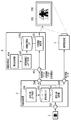
- FIG. 8 is a block diagram showing the configuration of the image display system in the present embodiment.
- the image processing apparatus 2 according to the present embodiment is different from the first embodiment in that the image processing apparatus 2 includes a fluctuation range information acquisition unit 207. Details of the processing by the fluctuation range information acquisition unit 207 will be described later.
- the signal decomposition LUT creation unit 206 in the present embodiment acquires the fluctuation range information and creates the signal decomposition LUT 203. Details of the signal decomposition LUT creation processing will be described later.
- the user first selects “light source selection” to input multiple types of ambient light source, “color temperature specification” to enter the range of ambient light color temperature numerically, and “spectral distribution specification” to specify multiple spectral distribution profiles. Select one with the check box.
- “light source selection” for example, fluorescent lamp, halogen, outdoor (daytime), and the like are displayed.
- the user selects a plurality of assumed light source types.
- “Specify color temperature” is selected, the upper and lower limits of the color temperature are selected by moving the slider bar left and right.
- “Spectral distribution designation” is selected, spectral distribution profile data acquired by a spectral sensor or the like is acquired.
- the user selects a plurality of assumed spectral profiles.
- a corresponding spectral distribution profile is set in advance.
- the plurality of spectral distribution profiles are sent to the signal decomposition LUT creation unit 206 as variation range information.
- the signal decomposition LUT creation unit 206 acquires the fluctuation range information from the fluctuation range information acquisition unit 207. That is, a plurality of ambient light spectral distribution profiles are acquired. Further, the signal decomposition LUT creation unit 206 calculates the average of the spectral distribution profiles, and calculates Smean ( ⁇ ) as the spectral distribution profile of the average ambient light.
- the signal decomposition LUT creation unit 206 calculates the XYZ values of the superimposed colors corresponding to the projector RGB values and printer RGB values acquired in S402 by the following equation (2).
- the XYZ values of the superimposed colors are calculated using the average environmental light Smean ( ⁇ ) as the reference environmental light instead of the environmental light Sill ( ⁇ ) used in the equation (1).
- the correction amount by the projection image correction unit 402 is also small.
- the correction amount by the projection image correction unit 402 may exceed the correction limit.
- the average Ambient light Smean ( ⁇ ) (slightly red, color temperature 5000K) is used as the reference ambient light.
- the printed image 501 formed at this time looks slightly blue when observed in the daytime period without projection light, and appears slightly red in the evening time period. In other words, the difference between the acquired ambient light and the reference ambient light is almost the same in any time zone, but the difference is unlikely to increase. Therefore, the possibility of exceeding the limit of correction by the projection image correction unit 402 can be reduced.
- the printer RGB and the projector RGB are determined using the range in which the ambient light can be changed.
- the color of the input image can be faithfully reproduced.
- Equation (3) the calculation of the superimposed color in S405 can be performed using equation (3) as follows.
- FIG. 10 shows an example of the reference environment light setting UI 1000.
- the user can set the reference ambient light by moving the slider bar shown at the bottom of the reference ambient light setting UI 1000 left and right.
- a preview image is displayed on the upper part of the reference environment light setting UI 1000 in accordance with the movement of the slider bar.
- the preview image is obtained by estimating superimposed images at the upper limit and the lower limit of the fluctuation range information acquired by the fluctuation range information acquisition unit 207.
- any preview image is the same as the input image.
- the correction amount by the projection image correction unit 402 is outside the correctable range, at least one preview image is different from the input image.
- the user can adjust the reference ambient light with the slider bar while judging whether this change is acceptable. Note that only a region where the preview image and the input image are different may be extracted and displayed as an image. That is, the signal decomposition processing unit 202 generates print image data and projection image data so that the correction amount by the projection image correction unit 402 is within a correctable range with respect to a predetermined range of ambient light information.
- FIG. 11 shows the configuration of the image display system in this case.
- a print image correction unit 1101 corrects print image data.
- a print image correction LUT creation unit 1103 creates a print image correction LUT 1002.
- the process of correcting the print image data can be realized by replacing the projection image and the print image in the processes performed by the projection image correction unit 402, the projection image correction LUT 403, and the projection image correction LUT creation unit 405.
- the image projection device 4 includes the projection image correction unit 402.
- the image processing device 2 may include the projection image correction unit 402.
- the configuration of the image display system in this case is shown in FIG. As described above, since the color variation may be compensated by the print image, the image processing apparatus 2 may include the print image correction unit 1101.
- the correction LUT is created based on the ambient light information.
- the method for determining the correction LUT is not limited to the above-described example.
- one correction LUT may be selected from a plurality of types of correction LUTs created in advance based on ambient light information.
- the present invention supplies a program that realizes one or more functions of the above-described embodiments to a system or apparatus via a network or a storage medium, and one or more processors in a computer of the system or apparatus read and execute the program
- This process can be realized. It can also be realized by a circuit (for example, ASIC) that realizes one or more functions.
Abstract
The present invention provides an image processing device that can more faithfully reproduce the colors of an input image in different environmental lights, without preparing a different a signal analysis LUT for each environmental light. An image processing device according to one embodiment of the present invention superimposes an image formed by an image forming device and an image projected by an image projection device, and generates data for generating a superimposed image. The image processing device is characterized by comprising: a generation means that, on the basis of input image data, generates first image data corresponding to the image forming device and second image data corresponding the image projection device; a first acquisition means that acquires environmental light information regarding environmental light for when the superimposed image is to be generated; and a correction means that corrects the second image data on the basis of the environmental light information.
Description
本発明は、プリンタとプロジェクタを用いて画像を表示する技術に関する。
The present invention relates to a technique for displaying an image using a printer and a projector.
近年、広いダイナミックレンジを持った被写体を撮影した場合に、ハイライトからシャドウ部まで情報量が保存された画像を記録するハイダイナミックレンジ画像(HDR画像)取得機能を備えたデジタルカメラ等が増えてきている。表示デバイスや出力デバイスでは、このようなHDR画像を忠実に再現することが求められる。特に、表示デバイスとして画像を大画面で表示できるプロジェクタや、出力デバイスとして高精細な大判出力が可能な大判プリンタ等は、実物(被写体)を迫力のあるサイズで表現できるため、その利用が期待されている。
In recent years, there has been an increase in digital cameras equipped with a high dynamic range image (HDR image) acquisition function that records an image in which an amount of information is stored from a highlight to a shadow portion when a subject having a wide dynamic range is photographed. ing. Display devices and output devices are required to faithfully reproduce such HDR images. In particular, projectors capable of displaying images on a large screen as display devices and large-format printers capable of high-definition large-format output as output devices can express the actual object (subject) in a powerful size and are expected to be used. ing.
しかしながら、プロジェクタや大判プリンタ等が扱うことのできる画像のダイナミックレンジや色域は、HDR画像を再現するには十分ではない。そのため、HDR画像をこれらのデバイスで表示したり出力したりする場合は、入力画像(すなわち、HDR画像)に対してトーンマッピングと呼ばれる階調圧縮処理や、色域圧縮処理が施される。その結果、これらのデバイスから出力される出力画像は、入力画像に忠実なものではなくなってしまう。
However, the dynamic range and color gamut of images that can be handled by projectors and large-format printers are not sufficient to reproduce HDR images. Therefore, when displaying or outputting an HDR image with these devices, a gradation compression process called tone mapping or a color gamut compression process is performed on the input image (that is, the HDR image). As a result, the output image output from these devices is not faithful to the input image.
そこで、複数のデバイスを用いて、入力画像のダイナミックレンジや色域をより忠実に再現する技術が提案されている。特許文献1には、プリンタによる印刷画像と、プロジェクタによる投影画像とを重畳させることで、より広いダイナミックレンジや色域で入力画像を表現することが開示されている。具体的には、プロジェクタにおける分光分布特性と、プリンタにおける分光反射率特性とに基づいて生成された信号分解LUT(ルックアップテーブル)を用いて、入力画像をプロジェクタ用の画像信号とプリンタ用の画像信号に変換する。そして、変換後の画像信号に基づいてプロジェクタおよびプリンタのそれぞれで形成された画像を重畳させる。また、特許文献1には、信号分解LUTの作成時に、画像の観察環境における光源(以下、環境光ともいう)の影響を考慮して、入力画像の色を忠実に再現することが開示されている。
Therefore, a technique for reproducing the dynamic range and color gamut of the input image more faithfully using a plurality of devices has been proposed. Patent Document 1 discloses that an input image is expressed with a wider dynamic range or color gamut by superimposing a print image by a printer and a projection image by a projector. Specifically, a signal decomposition LUT (lookup table) generated based on the spectral distribution characteristic in the projector and the spectral reflectance characteristic in the printer is used to convert the input image into an image signal for the projector and an image for the printer. Convert to signal. Then, the images formed by the projector and the printer are superimposed on the basis of the converted image signal. Further, Patent Document 1 discloses that the color of an input image is faithfully reproduced in consideration of the influence of a light source (hereinafter also referred to as ambient light) in an image observation environment when creating a signal decomposition LUT. Yes.
しかしながら、特許文献1に開示された技術では、異なる環境光に対応するために、環境光毎に異なる信号分解LUTを用意する必要があり、信号分解LUTのデータ量が増加してしまう。
However, in the technique disclosed in Patent Document 1, it is necessary to prepare different signal decomposition LUTs for each environmental light in order to cope with different environmental lights, and the data amount of the signal decomposition LUT increases.
そこで、本発明は、環境光毎に異なる信号分解LUTを用意することなく、異なる環境光下で入力画像の色をより忠実に再現することを目的とする。
Therefore, an object of the present invention is to more faithfully reproduce the color of an input image under different ambient light without preparing a different signal decomposition LUT for each ambient light.
本発明の一実施形態における画像処理装置は、画像形成装置によって形成される画像と、画像投影装置によって投影される画像と、を重畳して、重畳画像を生成するためのデータを生成する。当該画像処理装置は、入力画像データに基づいて、前記画像形成装置に対応する第1の画像データと、前記画像投影装置に対応する第2の画像データと、を生成する生成手段と、前記重畳画像が生成される際の環境光に関する環境光情報を取得する第1取得手段と、前記環境光情報に基づいて、前記第2の画像データを補正する補正手段と、
を備えることを特徴とする。 An image processing apparatus according to an embodiment of the present invention generates data for generating a superimposed image by superimposing an image formed by an image forming apparatus and an image projected by an image projection apparatus. The image processing apparatus generates, based on input image data, first image data corresponding to the image forming apparatus and second image data corresponding to the image projection apparatus, and the superimposing First acquisition means for acquiring ambient light information related to ambient light when an image is generated, and correction means for correcting the second image data based on the ambient light information;
It is characterized by providing.
本発明によると、異なる環境光下で入力画像の色をより忠実に再現することが可能となる。
According to the present invention, the color of the input image can be reproduced more faithfully under different ambient light.
本発明の更なる特徴は、添付の図面を参照して行う以下の実施形態の説明より明らかになる。
Further features of the present invention will become apparent from the following description of embodiments with reference to the accompanying drawings.
Further features of the present invention will become apparent from the following description of embodiments with reference to the accompanying drawings.
以下、本発明の実施形態について、図面を参照して詳細に説明する。なお、以下の実施形態は本発明を限定するものではなく、また、本実施形態で説明されている特徴の組み合わせの全てが本発明に必須のものとは限らない。なお、同一の構成については、同じ符号を付して説明する。
Hereinafter, embodiments of the present invention will be described in detail with reference to the drawings. The following embodiments do not limit the present invention, and not all combinations of features described in the present embodiment are essential to the present invention. In addition, about the same structure, the same code | symbol is attached | subjected and demonstrated.
本実施形態では、画像投影装置が分光センサを用いて環境光(すなわち、環境光情報)を取得し、環境光の変化が重畳色に与える色変動を、投影画像によって補償する例について説明する。
In the present embodiment, an example will be described in which an image projection apparatus acquires ambient light (that is, ambient light information) using a spectroscopic sensor, and the projection image compensates for a color variation that a change in the ambient light gives to the superimposed color.
(装置の構成)
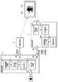
図1は、本実施形態における画像表示システムの構成を示すブロック図である。図1において、1は入力画像、2は画像処理装置(PC)、3は画像形成装置(プリンタ)、4は画像投影装置(プロジェクタ)をそれぞれ示す。画像表示システムは、画像形成装置3によって記録媒体上に形成された印刷画像501の上に、画像投影装置4によって投影された投影画像502を重ねることで、入力画像1のダイナミックレンジや色域をより忠実に再現する重畳画像を表示することができる。 (Device configuration)
FIG. 1 is a block diagram showing a configuration of an image display system in the present embodiment. In FIG. 1, 1 is an input image, 2 is an image processing apparatus (PC), 3 is an image forming apparatus (printer), and 4 is an image projection apparatus (projector). The image display system superimposes theprojection image 502 projected by the image projection device 4 on the print image 501 formed on the recording medium by the image forming device 3, thereby reducing the dynamic range and color gamut of the input image 1. A superimposed image that is reproduced more faithfully can be displayed.
図1は、本実施形態における画像表示システムの構成を示すブロック図である。図1において、1は入力画像、2は画像処理装置(PC)、3は画像形成装置(プリンタ)、4は画像投影装置(プロジェクタ)をそれぞれ示す。画像表示システムは、画像形成装置3によって記録媒体上に形成された印刷画像501の上に、画像投影装置4によって投影された投影画像502を重ねることで、入力画像1のダイナミックレンジや色域をより忠実に再現する重畳画像を表示することができる。 (Device configuration)
FIG. 1 is a block diagram showing a configuration of an image display system in the present embodiment. In FIG. 1, 1 is an input image, 2 is an image processing apparatus (PC), 3 is an image forming apparatus (printer), and 4 is an image projection apparatus (projector). The image display system superimposes the
なお、以下の実施形態においては、画像形成装置3をインクジェットプリンタ、画像投影装置4を液晶プロジェクタとして説明する。
In the following embodiments, the image forming apparatus 3 will be described as an ink jet printer, and the image projecting apparatus 4 will be described as a liquid crystal projector.
画像処理装置2は、例えば一般的なパーソナルコンピュータにインストールされたプリンタドライバによって実施され得る。その場合、以下に説明する画像処理装置2の各部は、コンピュータのCPUが所定のメモリまたは記憶装置に記憶されたプログラムを実行することにより実現される。また、別の構成として、例えば、画像形成装置3と画像投影装置4のいずれか、または両方を、画像処理装置2が含む構成としても良い。
The image processing apparatus 2 can be implemented by, for example, a printer driver installed in a general personal computer. In that case, each part of the image processing apparatus 2 described below is realized by the CPU of the computer executing a program stored in a predetermined memory or storage device. As another configuration, for example, the image processing device 2 may include one or both of the image forming device 3 and the image projection device 4.
画像処理装置2は、画像データ入力端子201より入力画像データを受け取る。入力された画像データは信号分解処理部202へ送られる。本実施形態では、重畳画像の各画素の再現目標となる三刺激値Xt、Yt、Ztが入力画像データとして入力される。
The image processing apparatus 2 receives input image data from the image data input terminal 201. The input image data is sent to the signal decomposition processing unit 202. In the present embodiment, tristimulus values Xt, Yt, and Zt that are reproduction targets of each pixel of the superimposed image are input as input image data.
なお、入力画像データは上記に限らず、たとえばRGB各8ビットの3チャンネルカラー画像を入力画像として入力してもよい。その場合、画像処理装置2は不図示の色変換処理部を備え、入力画像の各画素に対し、RGBからCIEXYZ(CIE(国際照明委員会)により定義されたXYZ色空間)への変換処理を行う。そうすることで、画像処理装置2は、重畳画像の再現目標となる三刺激値Xt、Yt、Ztを取得する。
Note that the input image data is not limited to the above, and, for example, an RGB 8-bit 3-channel color image may be input as the input image. In this case, the image processing apparatus 2 includes a color conversion processing unit (not shown), and performs conversion processing from RGB to CIEXYZ (XYZ color space defined by CIE (International Lighting Commission)) for each pixel of the input image. Do. By doing so, the image processing apparatus 2 acquires the tristimulus values Xt, Yt, and Zt that are the reproduction target of the superimposed image.
信号分解処理部202は、上記三刺激値Xt、Yt、Zt(すなわち、入力画像データ)から、画像形成装置3に送出する印刷画像データと、画像投影装置4に送出する投影画像データとを生成する。このとき、信号分解処理部202は、信号分解LUT(ルックアップテーブル)203を参照して、信号分解処理(すなわち、画像データ生成処理)を行う。
The signal decomposition processing unit 202 generates print image data to be sent to the image forming apparatus 3 and projection image data to be sent to the image projection apparatus 4 from the tristimulus values Xt, Yt and Zt (that is, input image data). To do. At this time, the signal decomposition processing unit 202 performs signal decomposition processing (that is, image data generation processing) with reference to the signal decomposition LUT (lookup table) 203.
図2は、本実施形態における信号分解LUT203の例を示す。図示されるように、信号分解LUT203には、三刺激値XYZの各格子点に対応した、プリンタRGBとプロジェクタのRGBとの組み合わせが格納されている。これらの組み合わせは、格子点の三刺激値と重畳画像の三刺激値が等しくなるよう、あらかじめ作成されている。信号分解LUT203の作成は、信号分解LUT作成部206によって行われる。信号分解LUT作成処理の詳細については後述する。
FIG. 2 shows an example of the signal decomposition LUT 203 in the present embodiment. As shown in the figure, the signal decomposition LUT 203 stores a combination of printer RGB and projector RGB corresponding to each lattice point of the tristimulus values XYZ. These combinations are created in advance so that the tristimulus values of the lattice points and the tristimulus values of the superimposed image are equal. The signal decomposition LUT 203 is created by the signal decomposition LUT creation unit 206. Details of the signal decomposition LUT creation processing will be described later.
信号分解処理部202が算出した印刷画像データは、出力端子204から画像形成装置3へと送出される。画像形成装置3は、取得した印刷画像データを用いて、印刷画像501を形成する。
The print image data calculated by the signal decomposition processing unit 202 is sent from the output terminal 204 to the image forming apparatus 3. The image forming apparatus 3 forms a print image 501 using the acquired print image data.
一方、出力端子205からは、投影画像データと印刷画像データの両方が、画像投影装置4へと送出される。また、基準環境光の情報も送出される。ここで基準環境光とは、信号分解LUT203の作成において、重畳色のXYZを算出する際に用いられる環境光である。詳細は後述する。
On the other hand, both the projection image data and the print image data are sent from the output terminal 205 to the image projection apparatus 4. Information on the reference ambient light is also sent out. Here, the reference ambient light is ambient light used when calculating XYZ of the superimposed color in the creation of the signal decomposition LUT 203. Details will be described later.
画像投影装置4は、入力端子401より投影画像データ、印刷画像データと、基準環境光の情報を受けとる。
The image projection device 4 receives projection image data, print image data, and reference ambient light information from the input terminal 401.
投影画像データは、投影画像補正部402により補正される。すなわち、投影画像補正部402は、投影画像データ補正手段として機能する。このとき、投影画像補正部402は、投影画像補正LUT403を参照して、投影画像データを補正する。
The projection image data is corrected by the projection image correction unit 402. That is, the projection image correction unit 402 functions as a projection image data correction unit. At this time, the projection image correction unit 402 corrects the projection image data with reference to the projection image correction LUT 403.
投影画像補正LUT403は、信号分解LUT203と同様に、プリンタRGB、プロジェクタRGB、重畳色のXYZが格納されたLUTである。ただし、入出力の関係が異なっている。即ち、信号分解LUT203は、XYZが入力、プリンタRGBとプロジェクタRGBが出力となるXYZ-RGBRGBのLUTである。一方、投影画像補正LUT403は、プリンタRGBとXYZが入力、プロジェクタRGBが出力となるRGBXYZ-RGBのLUTである。
The projection image correction LUT 403 is an LUT in which printer RGB, projector RGB, and superimposition color XYZ are stored, as in the signal decomposition LUT 203. However, the input / output relationship is different. That is, the signal decomposition LUT 203 is an XYZ-RGBRGB LUT in which XYZ is input and printer RGB and projector RGB are output. On the other hand, the projection image correction LUT 403 is an RGBXYZ-RGB LUT in which printers RGB and XYZ are input and projector RGB is an output.
投影画像補正LUT403は、投影画像補正LUT作成部405により作成される。投影画像補正LUT作成の詳細については後述する。
The projection image correction LUT 403 is created by the projection image correction LUT creation unit 405. Details of creating the projection image correction LUT will be described later.
環境光取得部404は、重畳画像が表示される環境の環境光情報を取得する。取得した環境光情報は、投影画像補正LUT作成部405へ送出される。
The ambient light acquisition unit 404 acquires ambient light information of the environment where the superimposed image is displayed. The acquired ambient light information is sent to the projection image correction LUT creation unit 405.
投影画像補正LUT作成部405は、環境光が基準環境光と異なる場合に、投影画像補正LUT403を作成する。
The projection image correction LUT creation unit 405 creates the projection image correction LUT 403 when the ambient light is different from the reference ambient light.
(信号分解処理部202における信号分解処理)
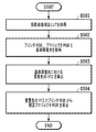
以下、図3に示すフローチャートを用いて、信号分解処理部202における信号分解処理の流れを説明する。なお、フローチャートで示される一連の処理は、CPUがROMに格納されているプログラムをRAMに展開し、実行することに行われる。あるいはまた、フローチャートにおけるステップの一部または全部の機能をASICや電子回路等のハードウェアで実現してもよい。各処理の説明における記号「S」は、当該フローチャートにおけるステップを意味する。その他のフローチャートについても同様である。 (Signal decomposition processing in the signal decomposition processing unit 202)
Hereinafter, the flow of the signal decomposition processing in the signaldecomposition processing unit 202 will be described using the flowchart shown in FIG. The series of processes shown in the flowchart is performed by the CPU expanding and executing the program stored in the ROM on the RAM. Alternatively, some or all of the steps in the flowchart may be realized by hardware such as an ASIC or an electronic circuit. The symbol “S” in the description of each process means a step in the flowchart. The same applies to other flowcharts.
以下、図3に示すフローチャートを用いて、信号分解処理部202における信号分解処理の流れを説明する。なお、フローチャートで示される一連の処理は、CPUがROMに格納されているプログラムをRAMに展開し、実行することに行われる。あるいはまた、フローチャートにおけるステップの一部または全部の機能をASICや電子回路等のハードウェアで実現してもよい。各処理の説明における記号「S」は、当該フローチャートにおけるステップを意味する。その他のフローチャートについても同様である。 (Signal decomposition processing in the signal decomposition processing unit 202)
Hereinafter, the flow of the signal decomposition processing in the signal
まず、S301において、信号分解処理部202は、信号分解LUT203を取得する。
First, in step S <b> 301, the signal decomposition processing unit 202 acquires the signal decomposition LUT 203.
次に、S302において、信号分解処理部202は、画像データ入力端子201より再現目標となる三刺激値Xt,Yt,Zt(すなわち、入力画像データ)を取得する。なお、取得に際しては、画像全体の再現目標の三刺激値Xt,Yt,Ztを取得して、不図示のメモリ内に展開してもよいし、1画素ずつ取得と処理を繰り返して行ってもよい。
Next, in S <b> 302, the signal decomposition processing unit 202 acquires tristimulus values Xt, Yt, Zt (that is, input image data) that are reproduction targets from the image data input terminal 201. When acquiring, the tristimulus values Xt, Yt, Zt of the reproduction target of the entire image may be acquired and expanded in a memory (not shown), or the acquisition and processing may be repeated for each pixel. Good.
次に、S303において、信号分解処理部202は、上述の信号分解LUTを用いて、補間処理等の周知の変換方法により、各画素の目標三刺激値Xt,Yt,Ztから、各画素に対するプロジェクタRGB値とプリンタRGB値を算出する。補間処理では、公知の四面体補間処理により、信号分解LUT203に格納されたプロジェクタRGB値とプリンタRGB値とから、各画素のプロジェクタRGB値とプリンタRGB値がそれぞれ算出される。
Next, in step S303, the signal decomposition processing unit 202 uses the signal decomposition LUT described above to perform a projector for each pixel from the target tristimulus values Xt, Yt, Zt of each pixel by a known conversion method such as interpolation processing. RGB values and printer RGB values are calculated. In the interpolation process, the projector RGB value and the printer RGB value of each pixel are calculated from the projector RGB value and the printer RGB value stored in the signal decomposition LUT 203 by a known tetrahedral interpolation process.
以上説明したS301~S303の処理により、再現目標の三刺激値Xt,Yt,Ztを重畳画像として再現するプリンタRGB値とプロジェクタRGB値とを算出することができる。
The printer RGB value and the projector RGB value for reproducing the reproduction target tristimulus values Xt, Yt, Zt as a superimposed image can be calculated by the processing of S301 to S303 described above.
(信号分解LUT203の作成方法)
以下、図4を参照して、信号分解LUT作成部206における、信号分解LUT203の作成方法について説明する。 (Method for creating signal decomposition LUT 203)
Hereinafter, a method of creating thesignal decomposition LUT 203 in the signal decomposition LUT creation unit 206 will be described with reference to FIG.
以下、図4を参照して、信号分解LUT作成部206における、信号分解LUT203の作成方法について説明する。 (Method for creating signal decomposition LUT 203)
Hereinafter, a method of creating the
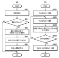
図4(a)に示すように、信号分解LUT作成部206は、まずRGBRGB-XYZのLUTを作成する(S40)。このLUTは、プリンタRGBとプロジェクタRGBを入力とし、重畳色のXYZを出力とする。S40の詳細は後述する。
As shown in FIG. 4A, the signal decomposition LUT creation unit 206 first creates an RGBRGB-XYZ LUT (S40). This LUT takes printer RGB and projector RGB as inputs, and outputs XYZ of superimposed colors. Details of S40 will be described later.
次いで、信号分解LUT作成部206は、RGBRGB-XYZのLUTを補間処理により逆引きすることで、XYZ-RGBRGBの信号分解LUT203を生成する(S41)。S41の詳細は後述する。
Next, the signal decomposition LUT creation unit 206 generates an XYZ-RGBRGB signal decomposition LUT 203 by reversely performing the RGBRGB-XYZ LUT by interpolation processing (S41). Details of S41 will be described later.
(RGBRGB-XYZのLUTの作成)
図4(b)は、RGBRGB-XYZのLUTの作成処理(S40)のフローチャートを示す図である。 (Create RGBRGB-XYZ LUT)
FIG. 4B is a flowchart of the RGBRGB-XYZ LUT creation process (S40).
図4(b)は、RGBRGB-XYZのLUTの作成処理(S40)のフローチャートを示す図である。 (Create RGBRGB-XYZ LUT)
FIG. 4B is a flowchart of the RGBRGB-XYZ LUT creation process (S40).
まず、S401において、信号分解LUT作成部206は、RGBRGBの格子信号を生成する。例えば、各色5グリッドで均等間隔となるRGBの格子値を、プリンタRGBとプロジェクタRGBのそれぞれに対して生成する。この場合、格子信号は5グリッドの6乗である15625通りとなる。
First, in S401, the signal decomposition LUT creation unit 206 generates RGBRGB lattice signals. For example, RGB grid values that are equally spaced by 5 grids for each color are generated for each of printer RGB and projector RGB. In this case, the number of lattice signals is 15625 which is the sixth power of 5 grids.
次にS402において、信号分解LUT作成部206は、S401で生成した格子信号のうちの1格子点に対応する、1つのRGBRGB値を取得する。
Next, in S402, the signal decomposition LUT creation unit 206 acquires one RGBRGB value corresponding to one grid point in the grid signal generated in S401.
そしてS403において、信号分解LUT作成部206は、S402で取得したプロジェクタRGB値に対応する、画像投影装置4の分光分布特性を取得する。画像投影装置4の分光分布特性は、予め所定のRGB値に対する分光分布を測定することで得られており、分光分布プロファイルとして記憶されている。なお、分光分布プロファイルに注目RGB値と一致するRGB値が含まれていない場合には、補間処理等によって注目RGB値に対する分光分布特性を算出する。
In S403, the signal decomposition LUT creation unit 206 acquires the spectral distribution characteristics of the image projection device 4 corresponding to the projector RGB values acquired in S402. The spectral distribution characteristics of the image projection device 4 are obtained by measuring the spectral distribution with respect to predetermined RGB values in advance, and are stored as a spectral distribution profile. If the spectral distribution profile does not include an RGB value that matches the target RGB value, the spectral distribution characteristic for the target RGB value is calculated by interpolation processing or the like.
次にS404において、信号分解LUT作成部206は、S402で取得したプリンタRGB値に対応する、画像形成装置3の分光反射率特性を取得する。画像形成装置3の分光反射率特性は、予め所定のRGB値に基づいて対象となるメディアに印刷したパッチを測定するなどして得られており、例えば分光反射率プロファイルとして記憶されている。なお、分光反射率プロファイルに注目RGB値と一致するRGB値が含まれていない場合には、補間処理等によって注目RGB値に対する分光反射率特性を算出する。
Next, in S404, the signal decomposition LUT creation unit 206 acquires the spectral reflectance characteristics of the image forming apparatus 3 corresponding to the printer RGB values acquired in S402. The spectral reflectance characteristics of the image forming apparatus 3 are obtained in advance by measuring a patch printed on a target medium based on predetermined RGB values, and are stored as, for example, a spectral reflectance profile. If the spectral reflectance profile does not include an RGB value that matches the target RGB value, a spectral reflectance characteristic for the target RGB value is calculated by interpolation processing or the like.
次にS405において、信号分解LUT作成部206は、S402で取得したプロジェクタRGB値に基づく投影色と、プリンタRGB値に基づくプリント色とを重ねた際の、重畳色であるXYZ値を、以下の(1)式により算出する。
X(rgb1,rgb2)= ∫{Sprj(rgb1,λ) + Sill(λ)} Rprn(rgb2,λ) x(λ) dλ
Y(rgb1,rgb2)= ∫{Sprj(rgb1,λ) + Sill(λ)} Rprn(rgb2,λ) y(λ) dλ
Z(rgb1,rgb2)= ∫{Sprj(rgb1,λ) + Sill(λ)} Rprn(rgb2,λ) z(λ) dλ
・・・(1) In step S <b> 405, the signal decompositionLUT creation unit 206 calculates an XYZ value that is a superimposed color when the projection color based on the projector RGB value acquired in step S <b> 402 and the print color based on the printer RGB value are superimposed on each other as follows. Calculated by equation (1).
X (rgb1, rgb2) = ∫ {Sprj (rgb1, λ) + Sill (λ)} Rprn (rgb2, λ) x (λ) dλ
Y (rgb1, rgb2) == {Sprj (rgb1, λ) + Sill (λ)} Rprn (rgb2, λ) y (λ) dλ
Z (rgb1, rgb2) = ∫ {Sprj (rgb1, λ) + Sill (λ)} Rprn (rgb2, λ) z (λ) dλ
... (1)
X(rgb1,rgb2)= ∫{Sprj(rgb1,λ) + Sill(λ)} Rprn(rgb2,λ) x(λ) dλ
Y(rgb1,rgb2)= ∫{Sprj(rgb1,λ) + Sill(λ)} Rprn(rgb2,λ) y(λ) dλ
Z(rgb1,rgb2)= ∫{Sprj(rgb1,λ) + Sill(λ)} Rprn(rgb2,λ) z(λ) dλ
・・・(1) In step S <b> 405, the signal decomposition
X (rgb1, rgb2) = ∫ {Sprj (rgb1, λ) + Sill (λ)} Rprn (rgb2, λ) x (λ) dλ
Y (rgb1, rgb2) == {Sprj (rgb1, λ) + Sill (λ)} Rprn (rgb2, λ) y (λ) dλ
Z (rgb1, rgb2) = ∫ {Sprj (rgb1, λ) + Sill (λ)} Rprn (rgb2, λ) z (λ) dλ
... (1)
(1)式において、rgb1、rgb2はそれぞれプロジェクタRGBとプリンタRGBであり、X(rgb1,rgb2),Y(rgb1,rgb2),Z(rgb1,rgb2)は、それらのRGBの組み合わせに対応する重畳色のXYZ値である。また、λは波長を表し、Sprj(rgb1,λ)はrgb1に対する投影光の分光分布、Rprn(rgb2,λ)はrgb2に対するプリント物の分光反射率である。また、Sill(λ)は環境光の分光分布であり、x(λ),y(λ),z(λ)は2度視野のXYZ等色関数である。即ち、投影光の分光分布と環境光の分光分布を加算した光がプリント物に照射され、画像形成装置の分光反射率との積として反射されたものが、重畳色の分光分布となる。これにXYZ等色関数で重みづけしてから積分したものが、重畳色のXYZ値である。
In Equation (1), rgb1 and rgb2 are projector RGB and printer RGB, respectively, and X (rgb1, rgb2), Y (rgb1, rgb2), and Z (rgb1, rgb2) are superimpositions corresponding to combinations of these RGB. This is the XYZ value of the color. Further, λ represents a wavelength, Sprj (rgb1, λ) is a spectral distribution of projected light with respect to rgb1, and Rprn (rgb2, λ) is a spectral reflectance of the printed material with respect to rgb2. Further, Sill (λ) is a spectral distribution of ambient light, and x (λ), y (λ), and z (λ) are XYZ color matching functions with a double field of view. That is, the light obtained by adding the spectral distribution of the projection light and the spectral distribution of the ambient light is irradiated onto the printed matter and reflected as a product of the spectral reflectance of the image forming apparatus becomes the spectral distribution of the superimposed color. The XYZ value of the superimposition color is obtained by weighting this with an XYZ color matching function and then integrating it.
なお、本実施形態では環境光Sill(λ)として、CIE昼光D50の分光分布を用いる。ただし、環境光Sill(λ)は限定されず、例えば重畳画像を表示する環境光の分光分布が取得・推定できる場合には、その分光分布を用いることが望ましい。
In the present embodiment, the spectral distribution of the CIE daylight D50 is used as the ambient light Sill (λ). However, the ambient light Sill (λ) is not limited. For example, when the spectral distribution of the environmental light displaying the superimposed image can be acquired and estimated, it is desirable to use the spectral distribution.
次にS406において、信号分解LUT作成部206は、S401で生成した全ての格子信号に対するXYZ値を算出したか否かを判定する。全て算出済みであればS407に進み、そうでない場合はS402に戻り、まだXYZ値を算出していない格子信号に対する処理を行う。
Next, in S406, the signal decomposition LUT creation unit 206 determines whether or not the XYZ values for all the lattice signals generated in S401 have been calculated. If all have been calculated, the process proceeds to S407. If not, the process returns to S402, and processing is performed on a lattice signal for which an XYZ value has not yet been calculated.
次にS407において、信号分解LUT作成部206は、S401で生成したRGBRGB信号と、S405で算出したXYZ信号とをそれぞれ対応づけて、RGBRGB-XYZのLUTを作成する。
Next, in S407, the signal decomposition LUT creation unit 206 creates an RGBRGB-XYZ LUT by associating the RGBRGB signal generated in S401 with the XYZ signal calculated in S405.
以上で、RGBRGB-XYZのLUTの作成処理(S40)が完了し、XYZ-RGBRGBのLUTの作成処理(S41)を開始する。
This completes the RGBRGB-XYZ LUT creation process (S40), and starts the XYZ-RGBRGB LUT creation process (S41).
(XYZ-RGBRGBのLUTの作成)
図4(c)は、XYZ-RGBRGBのLUTの作成処理(S41)のフローチャートを示す図である。 (Create XYZ-RGBRGB LUT)
FIG. 4C is a flowchart of the XYZ-RGBRGB LUT creation process (S41).
図4(c)は、XYZ-RGBRGBのLUTの作成処理(S41)のフローチャートを示す図である。 (Create XYZ-RGBRGB LUT)
FIG. 4C is a flowchart of the XYZ-RGBRGB LUT creation process (S41).
まず、S408において、信号分解LUT作成部206は、XYZの格子信号を生成する。本実施形態では、S405で算出したXYZの再現可能域内に均等に分布するXYZ値を生成する。
First, in step S408, the signal decomposition LUT creation unit 206 generates an XYZ lattice signal. In the present embodiment, XYZ values that are evenly distributed within the XYZ reproducible range calculated in S405 are generated.
次に、S409において、信号分解LUT作成部206は、S408で生成した格子信号のうちの1格子点に対応する、1色のXYZ値を取得する。
Next, in S409, the signal decomposition LUT creation unit 206 acquires an XYZ value of one color corresponding to one grid point in the grid signal generated in S408.
そしてS410において、信号分解LUT作成部206は、S409で取得したXYZ値に対応するプロジェクタRGBとプリンタRGBを、S407で作成したRGBRGB-XYZのLUTから取得する。なお、注目XYZ値と一致するXYZ値が含まれていない場合には、補間処理等によって注目XYZ値に対するプロジェクタRGBおよびプリンタRGBを算出する。
In S410, the signal decomposition LUT creation unit 206 obtains the projector RGB and printer RGB corresponding to the XYZ values obtained in S409 from the RGBRGB-XYZ LUT created in S407. If an XYZ value that matches the target XYZ value is not included, projector RGB and printer RGB for the target XYZ value are calculated by interpolation processing or the like.
次にS411において、信号分解LUT作成部206は、S408で生成した全ての格子信号に対するRGBRGB値を算出したか否かを判定する。全て算出済みであればS412に進み、そうでない場合はS409に戻り、まだRGBRGB値を算出していない格子信号に対する処理が行われる。
Next, in S411, the signal decomposition LUT creation unit 206 determines whether or not the RGBRGB values for all the lattice signals generated in S408 have been calculated. If all have been calculated, the process proceeds to S412. If not, the process returns to S409, and processing is performed on a grid signal for which RGBRGB values have not yet been calculated.
次にS412において、信号分解LUT作成部206は、S408で生成したXYZ信号と、S410で算出したRGBRGB信号とをそれぞれ対応づけて、XYZ-RGBRGBの信号分解LUT203を作成する。
Next, in S412, the signal decomposition LUT creation unit 206 creates the XYZ-RGBRGB signal decomposition LUT 203 by associating the XYZ signal generated in S408 with the RGBRGB signal calculated in S410.
以上で、信号分解LUT203の作成処理が完了する。
Thus, the process of creating the signal decomposition LUT 203 is completed.
(投影画像補正部402における補正処理)
以下、図5に示すフローチャートを用いて、投影画像補正部402における投影画像補正処理の流れを説明する。 (Correction process in projection image correction unit 402)
Hereinafter, the flow of the projection image correction process in the projectionimage correction unit 402 will be described with reference to the flowchart shown in FIG.
以下、図5に示すフローチャートを用いて、投影画像補正部402における投影画像補正処理の流れを説明する。 (Correction process in projection image correction unit 402)
Hereinafter, the flow of the projection image correction process in the projection
まずS501において、投影画像補正部402は、投影画像補正LUT403を取得する。
First, in step S <b> 501, the projection image correction unit 402 acquires a projection image correction LUT 403.
次にS502において、投影画像補正部402は、入力端子401より、プリンタRGB、プロジェクタRGBと、基準環境光を取得する。
In step S <b> 502, the projection image correction unit 402 acquires printer RGB, projector RGB, and reference environment light from the input terminal 401.
次にS503において、投影画像補正部402は、基準環境光における重畳画像のXYZを画素毎に算出する。重畳色の算出は、上述の図4のS405の処理と同様であり、(1)式を用いる。
Next, in S503, the projection image correction unit 402 calculates the XYZ of the superimposed image in the reference environment light for each pixel. The calculation of the superimposed color is the same as the process of S405 in FIG.
そしてS504において、重畳画像のXYZとプリンタRGBから、投影画像補正LUT403を用い、各画素に対するプロジェクタRGB値を算出する。
In step S504, a projector RGB value for each pixel is calculated from the superimposed image XYZ and the printer RGB using the projection image correction LUT 403.
以上説明したS501~S504の処理により、環境光の変化(すなわち、異なる環境光)に応じてプロジェクタRGBを補正することができる。
Through the processing of S501 to S504 described above, the projector RGB can be corrected in accordance with changes in the environmental light (that is, different environmental lights).
(投影画像補正LUT403の作成方法)
以下、図6を参照して、投影画像補正LUT作成部405における、投影画像補正LUT作成処理の詳細について説明する。 (Method for creating projection image correction LUT 403)
Hereinafter, the details of the projection image correction LUT creation processing in the projection image correctionLUT creation unit 405 will be described with reference to FIG.
以下、図6を参照して、投影画像補正LUT作成部405における、投影画像補正LUT作成処理の詳細について説明する。 (Method for creating projection image correction LUT 403)
Hereinafter, the details of the projection image correction LUT creation processing in the projection image correction
図6(a)は、投影画像補正LUT作成処理のフローチャートを示す。
FIG. 6A shows a flowchart of the projection image correction LUT creation process.
まず、S60では、投影画像補正LUT作成部405は、環境光取得部404から環境光を取得する。
First, in S <b> 60, the projection image correction LUT creation unit 405 acquires ambient light from the ambient light acquisition unit 404.
次に、S61では、投影画像補正LUT作成部405は、取得した環境光が、想定環境光から変化したかを判定する。ここで想定環境光とは、以前に投影画像補正LUTを作成した際に用いた環境光である。初期状態では、想定環境光は基準環境光Sill(λ)であり、投影画像補正LUT作成処理後には、取得した環境光に置き換えられる。取得した環境光が変化していないと判定された場合は、投影画像補正LUTの作成は不要であるため、処理を終了する。一方、変化していると判定された場合は、S62へ進む。
Next, in S61, the projection image correction LUT creation unit 405 determines whether the acquired ambient light has changed from the assumed ambient light. Here, the assumed ambient light is the ambient light used when the projection image correction LUT was previously created. In the initial state, the assumed environment light is the reference environment light Sill (λ), and is replaced with the acquired environment light after the projection image correction LUT creation processing. If it is determined that the acquired ambient light has not changed, it is not necessary to create a projection image correction LUT, and thus the process ends. On the other hand, if it is determined that it has changed, the process proceeds to S62.
S62では、投影画像補正LUT作成部405は、RGBRGB-XYZのLUTを作成する。この処理は、図4(b)のS40の処理と同様であるため説明を省略する。ただしS62では、投影画像補正LUT作成部405は、S405の重畳色算出において、基準環境光Sill(λ)の代わりに、環境光取得部404より取得した環境光を用いてXYZを算出する。
In S62, the projection image correction LUT creation unit 405 creates an RGBRGB-XYZ LUT. Since this process is the same as the process of S40 in FIG. However, in S62, the projection image correction LUT creation unit 405 calculates XYZ using the environmental light acquired from the environmental light acquisition unit 404 instead of the reference environmental light Sill (λ) in the superimposed color calculation of S405.
次に、S63では、投影画像補正LUT作成部405は、RGBXYZ-RGBの投影画像補正LUTを作成する。このLUTは、プリンタRGBと重畳色のXYZを入力とし、プロジェクタRGBを出力とする。
Next, in S63, the projection image correction LUT creation unit 405 creates an RGBXYZ-RGB projection image correction LUT. This LUT receives printer RGB and superimposed colors XYZ and outputs projector RGB.
図6(b)は、S63における処理の詳細を示したフローチャートである。
FIG. 6B is a flowchart showing details of the process in S63.
まず、S601において、投影画像補正LUT作成部405は、RGBXYZの格子信号を生成する。本実施形態では、各色5グリッドで均等間隔となる値を、XYZとプリンタRGBのそれぞれに対して生成する。この場合、格子信号は5グリッドの6乗である15625通りとなる。
First, in step S601, the projection image correction LUT creation unit 405 generates RGBXYZ lattice signals. In the present embodiment, values that are equally spaced in 5 grids for each color are generated for each of XYZ and printer RGB. In this case, the number of lattice signals is 15625 which is the sixth power of 5 grids.
次にS602において、投影画像補正LUT作成部405は、S601で生成した格子信号のうちの1格子点に対応する、1つのRGBXYZ値を取得する。
Next, in S602, the projection image correction LUT creation unit 405 acquires one RGBXYZ value corresponding to one grid point of the grid signal generated in S601.
そしてS603において、投影画像補正LUT作成部405は、S602で取得したRGBXYZ値に対応するプロジェクタRGBを取得する。このとき、S62で作成したRGBRGB-XYZのLUTを参照し、注目RGBXYZ値と一致するRGBXYZ値が含まれていない場合には、補間処理等によって注目RGBXYZ値に対するプロジェクタRGBを取得する。
In step S603, the projection image correction LUT creation unit 405 acquires the projector RGB corresponding to the RGBXYZ value acquired in step S602. At this time, with reference to the RGBRGB-XYZ LUT created in S62, if the RGBXYZ value that matches the target RGBXYZ value is not included, the projector RGB for the target RGBXYZ value is acquired by interpolation processing or the like.
次にS604において、投影画像補正LUT作成部405は、全ての格子信号に対するプロジェクタRGB値を算出したか否かを判定する。全て算出済みであればS605に進み、そうでない場合はS602に戻り、まだプロジェクタRGB値を算出していない格子信号に対する処理を行う。
Next, in S604, the projection image correction LUT creation unit 405 determines whether or not the projector RGB values have been calculated for all the lattice signals. If all have been calculated, the process proceeds to S605. If not, the process returns to S602 to perform processing on the grid signal for which the projector RGB values have not yet been calculated.
次にS605において、投影画像補正LUT作成部405は、S601で生成したRGBXYZ信号と、S603で算出したプロジェクタRGB信号をそれぞれ対応づけて、RGBXYZ-RGBの投影画像補正LUT403を作成する。
In step S605, the projection image correction LUT creation unit 405 creates an RGBXYZ-RGB projection image correction LUT 403 by associating the RGBXYZ signal generated in step S601 with the projector RGB signal calculated in step S603.
以上でS63の処理が完了する。
This completes the processing of S63.
次に、S64では、投影画像補正LUT作成部405は、取得した環境光を保持する。ここで保持した環境光は、上述のS61における想定環境光であり、再び投影画像補正LUT403が作成された際に参照される。
Next, in S64, the projection image correction LUT creation unit 405 holds the acquired ambient light. The ambient light held here is the assumed ambient light in S61 described above, and is referred to when the projection image correction LUT 403 is created again.
以上で、投影画像補正LUT403の作成処理が完了する。
This completes the process of creating the projection image correction LUT 403.
以上説明したように、本実施形態によれば、分光センサを用いて環境光を取得し、環境光の変化が重畳色に与える影響を、投影画像によって補償することで、入力画像の色をより忠実に再現することができる。
As described above, according to the present embodiment, the ambient light is acquired using the spectroscopic sensor, and the influence of the change in the ambient light on the superimposed color is compensated by the projected image, thereby further improving the color of the input image. Can be faithfully reproduced.
(変形例)
なお、本実施形態では画像投影装置4への入力が3チャンネルのプロジェクタRGBである例について説明したが、信号の種類は限定されない。例えば、画像投影装置4が分光再現可能なマルチバンドプロジェクタである場合には、3チャンネル以上の分光信号値が入力される。なお、その場合には、図5に示す投影画像補正処理において、環境光変化の差分を分光的に直接補償することができるため、プリンタRGB取得(S502)や重畳色算出処理(S503)は必須ではない。 (Modification)
In the present embodiment, an example in which the input to theimage projection apparatus 4 is a three-channel projector RGB has been described, but the type of signal is not limited. For example, when the image projection device 4 is a multiband projector capable of spectral reproduction, spectral signal values of three or more channels are input. In this case, the projection image correction process shown in FIG. 5 can directly compensate for the difference in ambient light change, so that the printer RGB acquisition (S502) and the superimposed color calculation process (S503) are essential. is not.
なお、本実施形態では画像投影装置4への入力が3チャンネルのプロジェクタRGBである例について説明したが、信号の種類は限定されない。例えば、画像投影装置4が分光再現可能なマルチバンドプロジェクタである場合には、3チャンネル以上の分光信号値が入力される。なお、その場合には、図5に示す投影画像補正処理において、環境光変化の差分を分光的に直接補償することができるため、プリンタRGB取得(S502)や重畳色算出処理(S503)は必須ではない。 (Modification)
In the present embodiment, an example in which the input to the
また、本実施形態では図5に示す投影画像補正処理のS503において、(1)式を用いて基準環境光での重畳色を算出する構成としたが、重畳色の算出方法は限定されない。例えば、S40で作成するRGBRGB-XYZのLUTを用いてもよい。
In this embodiment, in step S503 of the projection image correction process shown in FIG. 5, the superimposed color with the reference ambient light is calculated using the equation (1). However, the method for calculating the superimposed color is not limited. For example, the RGBRGB-XYZ LUT created in S40 may be used.
また、本実施形態では環境光取得部404として、分光センサを用いて環境光を取得する例について説明したが、分光センサは一般的なカラーセンサに比べて高価であり、装置コストの増加を招く。そこで例えば、分光センサの代わりにRGBカラーセンサを用い、環境光の分光分布を推定する構成としてもよい。その場合、複数の既知の環境光における、RGBカラーセンサ値と分光分布とを対応づけたテーブルをあらかじめ作成・保持しておくことにより、取得した環境光のRGB値から環境光の分光分布が推定できる。勿論、上記の対応関係を数式として保持してもよい。
In this embodiment, an example in which ambient light is acquired using a spectroscopic sensor as the ambient light acquisition unit 404 has been described. However, the spectroscopic sensor is more expensive than a general color sensor and causes an increase in apparatus cost. . Therefore, for example, an RGB color sensor may be used instead of the spectroscopic sensor, and the spectral distribution of the ambient light may be estimated. In that case, the spectral distribution of the ambient light is estimated from the RGB values of the acquired ambient light by creating and holding in advance a table that associates the RGB color sensor values and the spectral distributions in a plurality of known ambient lights. it can. Of course, you may hold | maintain said correspondence as a numerical formula.
また、本実施形態では、環境光が想定環境光から変化したかを判定し、変化していると判定された場合に、投影画像補正処理を実行する例について説明したが、実行のタイミングは任意である。例えば、ユーザーが実行を指示する構成としてもよい。
Further, in the present embodiment, the example in which the projection image correction process is performed when it is determined whether the ambient light has changed from the assumed ambient light and it is determined that the ambient light has changed has been described. However, the execution timing is arbitrary. It is. For example, a configuration in which the user instructs execution is possible.
(投影画像補正LUT403をXYZ-RGBとして保持する変形例)
また、本実施形態では、投影画像補正LUT403として、RGBXYZ-RGBのLUTを用いる例を説明した。しかしながら、LUTの入力が6次元となるため格子点の数が多く、LUTを保持するために必要な記憶容量が大きくなってしまう。そこで、投影画像補正LUT403として、入力が重畳色のXYZ、出力が補正後のプロジェクタRGBとなるXYZ-RGBのLUTを用いる変形例について説明する。 (Modification in which projectionimage correction LUT 403 is held as XYZ-RGB)
In the present embodiment, an example in which an RGBXYZ-RGB LUT is used as the projectionimage correction LUT 403 has been described. However, since the input of the LUT is 6-dimensional, the number of lattice points is large, and the storage capacity necessary to hold the LUT is increased. Therefore, a modified example using an XYZ-RGB LUT in which the input is the superimposed color XYZ and the output is the corrected projector RGB as the projection image correction LUT 403 will be described.
また、本実施形態では、投影画像補正LUT403として、RGBXYZ-RGBのLUTを用いる例を説明した。しかしながら、LUTの入力が6次元となるため格子点の数が多く、LUTを保持するために必要な記憶容量が大きくなってしまう。そこで、投影画像補正LUT403として、入力が重畳色のXYZ、出力が補正後のプロジェクタRGBとなるXYZ-RGBのLUTを用いる変形例について説明する。 (Modification in which projection
In the present embodiment, an example in which an RGBXYZ-RGB LUT is used as the projection
図7(a)は、投影画像補正LUT作成部405における、投影画像補正LUT作成処理のフローチャートを示す。
FIG. 7A shows a flowchart of the projection image correction LUT creation process in the projection image correction LUT creation unit 405.
S70、S71、S72、およびS74の処理は、上述のS60、S61、S62およびS64の処理と同様であるため説明を省略する。
Since the processes of S70, S71, S72, and S74 are the same as the processes of S60, S61, S62, and S64 described above, description thereof is omitted.
図7(b)は、S73におけるXYZ-RGBの投影画像補正LUTの作成処理のフローチャートを示す。
FIG. 7B is a flowchart of the process for creating the XYZ-RGB projected image correction LUT in S73.
まず、S701において、投影画像補正LUT作成部405は、XYZの格子信号を生成する。例えば、各色5グリッドで均等間隔となる値を生成する。
First, in S701, the projection image correction LUT creation unit 405 generates an XYZ lattice signal. For example, the value which becomes a uniform space | interval in each color 5 grid is produced | generated.
次にS702において、投影画像補正LUT作成部405は、S701で生成した格子信号のうちの1格子点に対応する、1色のXYZ値を取得する。
Next, in S702, the projection image correction LUT creation unit 405 acquires an XYZ value of one color corresponding to one grid point in the grid signal generated in S701.
そしてS703において、投影画像補正LUT作成部405は、S702で取得したXYZ値との平均誤差が最小となるプロジェクタRGBを取得する。ここで平均誤差とは、あるプロジェクタRGBを複数のプリンタRGBに対して重畳した時のXYZを、RGBRGB-XYZのLUTからそれぞれ取得し、上記格子点のXYZとの誤差を算出した後、誤差を平均化したものである。
In step S703, the projection image correction LUT creation unit 405 acquires the projector RGB that minimizes the average error from the XYZ values acquired in step S702. Here, the average error is obtained by obtaining the XYZ when a certain projector RGB is superimposed on a plurality of printers RGB from the RGBRGB-XYZ LUT, calculating the error from the grid points XYZ, and then calculating the error. Averaged.
S704およびS705は、上述のS604およびS605と同様であるため説明を省略する。
Since S704 and S705 are the same as S604 and S605 described above, description thereof will be omitted.
上述の実施形態では、環境光の変化の影響を投影画像によって補償する例について説明した。しかしながら、環境光の変化が大きい場合には、投影画像で補償しきれず、入力画像の色を忠実に再現できないことがある。そこで本実施形態では、環境光の変化しうる範囲(以下、変動範囲情報)を取得し、変動範囲情報を用いてプリンタRGBとプロジェクタRGBを決定することで、環境光の変化が大きい場合にも入力画像の色を忠実に再現する例について説明する。なお、上述の実施形態と共通の部分については説明を簡易化または省略する。
In the above-described embodiment, the example in which the influence of the change in ambient light is compensated by the projection image has been described. However, when the change in ambient light is large, the projection image cannot be fully compensated, and the color of the input image may not be faithfully reproduced. Therefore, in the present embodiment, a range in which ambient light can change (hereinafter referred to as fluctuation range information) is acquired, and printer RGB and projector RGB are determined using the fluctuation range information, so that even when the change in ambient light is large An example of faithfully reproducing the color of the input image will be described. In addition, description is simplified or abbreviate | omitted about the part which is common in the above-mentioned embodiment.
図8は、本実施形態における画像表示システムの構成を示すブロック図である。本実施形態における画像処理装置2は、変動範囲情報取得部207を備える点で、第1の実施形態と異なる。変動範囲情報取得部207による処理の詳細については後述する。
FIG. 8 is a block diagram showing the configuration of the image display system in the present embodiment. The image processing apparatus 2 according to the present embodiment is different from the first embodiment in that the image processing apparatus 2 includes a fluctuation range information acquisition unit 207. Details of the processing by the fluctuation range information acquisition unit 207 will be described later.
本実施形態における信号分解LUT作成部206は、変動範囲情報を取得し、信号分解LUT203を作成する。信号分解LUT作成処理の詳細については後述する。
The signal decomposition LUT creation unit 206 in the present embodiment acquires the fluctuation range information and creates the signal decomposition LUT 203. Details of the signal decomposition LUT creation processing will be described later.
(変動範囲情報取得)
以下、図9を参照して、変動範囲情報取得部207による処理について説明する。ユーザーは、図9に示すGUI900を用いて、変動範囲情報を設定することができる。 (Change range information acquisition)
Hereinafter, with reference to FIG. 9, the process by the fluctuation rangeinformation acquisition unit 207 will be described. The user can set the fluctuation range information using the GUI 900 shown in FIG.
以下、図9を参照して、変動範囲情報取得部207による処理について説明する。ユーザーは、図9に示すGUI900を用いて、変動範囲情報を設定することができる。 (Change range information acquisition)
Hereinafter, with reference to FIG. 9, the process by the fluctuation range
ユーザーは、まず、環境光の光源種類を複数入力する「光源選択」、環境光の色温度の範囲を数値で入力する「色温度指定」、分光分布プロファイルを複数指定する「分光分布指定」のいずれかを、チェックボックスで選択する。「光源選択」が選択された場合、その候補としてたとえば、蛍光灯、ハロゲン、屋外(昼)、などが表示される。ユーザーは、想定される光源の種類を複数選択する。また、「色温度指定」が選択された場合、スライダーバーを左右に移動させることにより、色温度の上限と下限が選択される。また、「分光分布指定」が選択された場合、分光センサ等で取得された分光分布プロファイルデータを取得する。ユーザーは、想定される分光プロファイルを複数選択する。
The user first selects “light source selection” to input multiple types of ambient light source, “color temperature specification” to enter the range of ambient light color temperature numerically, and “spectral distribution specification” to specify multiple spectral distribution profiles. Select one with the check box. When “light source selection” is selected, for example, fluorescent lamp, halogen, outdoor (daytime), and the like are displayed. The user selects a plurality of assumed light source types. When “Specify color temperature” is selected, the upper and lower limits of the color temperature are selected by moving the slider bar left and right. When “Spectral distribution designation” is selected, spectral distribution profile data acquired by a spectral sensor or the like is acquired. The user selects a plurality of assumed spectral profiles.
なお、本実施形態では、「光源選択」、「色温度指定」における候補が選択された場合は、予め対応した分光分布プロファイルが設定されることとする。上記複数の分光分布プロファイルは、変動範囲情報として、信号分解LUT作成部206へ送出される。
In the present embodiment, when a candidate in “light source selection” and “color temperature designation” is selected, a corresponding spectral distribution profile is set in advance. The plurality of spectral distribution profiles are sent to the signal decomposition LUT creation unit 206 as variation range information.
(信号分解LUT203の作成方法)
以下、本実施形態における信号分解LUT203の作成方法について説明する。第1の実施形態と共通の部分については、説明を省略する。本実施形態では、図4(b)に示す重畳色の算出(S405)が、第1の実施形態と異なる。 (Method for creating signal decomposition LUT 203)
Hereinafter, a method of creating thesignal decomposition LUT 203 in the present embodiment will be described. Description of parts common to the first embodiment is omitted. In the present embodiment, the calculation of the superimposed color (S405) shown in FIG. 4B is different from that in the first embodiment.
以下、本実施形態における信号分解LUT203の作成方法について説明する。第1の実施形態と共通の部分については、説明を省略する。本実施形態では、図4(b)に示す重畳色の算出(S405)が、第1の実施形態と異なる。 (Method for creating signal decomposition LUT 203)
Hereinafter, a method of creating the
S405では、まず、信号分解LUT作成部206は、変動範囲情報取得部207から変動範囲情報を取得する。即ち、複数の環境光の分光分布プロファイルを取得する。さらに、信号分解LUT作成部206は、分光分布プロファイルの平均を算出し、平均環境光の分光分布プロファイルとしてSmean(λ)を算出する。
In S405, first, the signal decomposition LUT creation unit 206 acquires the fluctuation range information from the fluctuation range information acquisition unit 207. That is, a plurality of ambient light spectral distribution profiles are acquired. Further, the signal decomposition LUT creation unit 206 calculates the average of the spectral distribution profiles, and calculates Smean (λ) as the spectral distribution profile of the average ambient light.
その後、信号分解LUT作成部206は、S402で取得したプロジェクタRGB値とプリンタRGB値に対応する重畳色のXYZ値を、以下の(2)式により算出する。
X(rgb1,rgb2)= ∫{Sprj(rgb1,λ) + Smean(λ)} Rprn(rgb2,λ) x(λ) dλ
Y(rgb1,rgb2)= ∫{Sprj(rgb1,λ) + Smean (λ)} Rprn(rgb2,λ) y(λ) dλ
Z(rgb1,rgb2)= ∫{Sprj(rgb1,λ) + Smean (λ)} Rprn(rgb2,λ) z(λ) dλ
・・・(2) Thereafter, the signal decompositionLUT creation unit 206 calculates the XYZ values of the superimposed colors corresponding to the projector RGB values and printer RGB values acquired in S402 by the following equation (2).
X (rgb1, rgb2) = ∫ {Sprj (rgb1, λ) + Smean (λ)} Rprn (rgb2, λ) x (λ) dλ
Y (rgb1, rgb2) == {Sprj (rgb1, λ) + Smean (λ)} Rprn (rgb2, λ) y (λ) dλ
Z (rgb1, rgb2) = ∫ {Sprj (rgb1, λ) + Smean (λ)} Rprn (rgb2, λ) z (λ) dλ
... (2)
X(rgb1,rgb2)= ∫{Sprj(rgb1,λ) + Smean(λ)} Rprn(rgb2,λ) x(λ) dλ
Y(rgb1,rgb2)= ∫{Sprj(rgb1,λ) + Smean (λ)} Rprn(rgb2,λ) y(λ) dλ
Z(rgb1,rgb2)= ∫{Sprj(rgb1,λ) + Smean (λ)} Rprn(rgb2,λ) z(λ) dλ
・・・(2) Thereafter, the signal decomposition
X (rgb1, rgb2) = ∫ {Sprj (rgb1, λ) + Smean (λ)} Rprn (rgb2, λ) x (λ) dλ
Y (rgb1, rgb2) == {Sprj (rgb1, λ) + Smean (λ)} Rprn (rgb2, λ) y (λ) dλ
Z (rgb1, rgb2) = ∫ {Sprj (rgb1, λ) + Smean (λ)} Rprn (rgb2, λ) z (λ) dλ
... (2)
即ち、本実施形態では、(1)式で用いた環境光Sill(λ)の代わりに、平均環境光Smean(λ)を基準環境光として用いて、重畳色のXYZ値を算出する。
That is, in the present embodiment, the XYZ values of the superimposed colors are calculated using the average environmental light Smean (λ) as the reference environmental light instead of the environmental light Sill (λ) used in the equation (1).
(平均環境光を用いる理由)
以下、平均環境光Smean(λ)を用いる理由について、具体例を挙げて説明する。 (Reason for using average ambient light)
Hereinafter, the reason for using the average ambient light Smean (λ) will be described with a specific example.
以下、平均環境光Smean(λ)を用いる理由について、具体例を挙げて説明する。 (Reason for using average ambient light)
Hereinafter, the reason for using the average ambient light Smean (λ) will be described with a specific example.
例として、基準環境光にCIE昼光D50を用い、重畳画像を表示する環境が屋外である場合を考える。この場合、昼の時間帯には、環境光取得部404が取得する環境光とSill(λ)との差異が小さい。そのため、投影画像補正部402による補正量も小さい。しかし、夕方の時間帯となり、環境光取得部404が取得する環境光の赤味が強くなる(色温度が低くなる)と、Sill(λ)との差異が大きくなる。その結果、投影画像補正部402による補正量が補正の限界を超えてしまう可能性がある。
As an example, consider the case where the environment for displaying the superimposed image is outdoors, using CIE daylight D50 as the reference ambient light. In this case, the difference between the ambient light acquired by the ambient light acquisition unit 404 and Sill (λ) is small during the daytime. For this reason, the correction amount by the projection image correction unit 402 is also small. However, when it becomes the evening time zone and the reddishness of the environmental light acquired by the environmental light acquisition unit 404 becomes strong (the color temperature decreases), the difference from Sill (λ) increases. As a result, the correction amount by the projection image correction unit 402 may exceed the correction limit.
一方、本実施形態では、重畳画像を表示する際の環境光が昼(白、色温度8000K)から夕方(赤、色温度2000K)の範囲で変化することが既知である場合に、その平均の環境光Smean(λ)(やや赤、色温度5000K)を基準環境光として用いる。このとき形成される印刷画像501は、投影光なしで昼の時間帯に観察するとやや青く見え、夕方の時間帯にはやや赤く見える。即ち、いずれの時間帯でも、取得した環境光と基準環境光との差異が同程度に生じるが、差異が大きくなることは起こりにくい。そのため、投影画像補正部402による補正の限界を超えてしまう可能性を低減できる。
On the other hand, in this embodiment, when it is known that the ambient light when displaying the superimposed image changes in the range from daytime (white, color temperature 8000K) to evening (red, color temperature 2000K), the average Ambient light Smean (λ) (slightly red, color temperature 5000K) is used as the reference ambient light. The printed image 501 formed at this time looks slightly blue when observed in the daytime period without projection light, and appears slightly red in the evening time period. In other words, the difference between the acquired ambient light and the reference ambient light is almost the same in any time zone, but the difference is unlikely to increase. Therefore, the possibility of exceeding the limit of correction by the projection image correction unit 402 can be reduced.
以上説明したように、本実施形態によれば、環境光の変化を投影画像で補償しきれない場合においても、環境光の変化しうる範囲を用いてプリンタRGBとプロジェクタRGBを決定することで、入力画像の色を忠実に再現することができる。
As described above, according to the present embodiment, even when the change in the ambient light cannot be compensated for by the projection image, the printer RGB and the projector RGB are determined using the range in which the ambient light can be changed. The color of the input image can be faithfully reproduced.
(プロジェクタの色再現域も考慮した変形例)
環境光の変動範囲情報に加えて、画像投影装置4の色再現範囲情報を用いて、基準環境光を決定してもよい。例えば、画像投影装置4の色再現範囲が赤色側に大きく、青色側に小さい場合には、基準環境光を赤側に寄せる(プリント物を青く寄せる)ほうが、補正の限界を超える可能性をより低減できる。そこで例えば、プロジェクタRGB=(255,0,0)、(0,255,0)、(0,0,255)の3色の分光分布の平均を取得し、全波長の合計が0になるようオフセットした分光分布をQprj(λ)と表す。その場合、S405における重畳色算出は、以下のように(3)式を用いて行うことができる。
X(rgb1,rgb2)= ∫{Sprj(rgb1,λ)+Smean(λ)+Qprj(λ)} Rprn(rgb2,λ) x(λ)dλ
Y(rgb1,rgb2)= ∫{Sprj(rgb1,λ)+Smean (λ)+Qprj(λ)} Rprn(rgb2,λ) y(λ)dλ
Z(rgb1,rgb2)= ∫{Sprj(rgb1,λ)+Smean (λ)+Qprj(λ)} Rprn(rgb2,λ) z(λ)dλ
・・・(3) (Modification taking into account the color reproduction range of the projector)
The reference ambient light may be determined using the color reproduction range information of theimage projector 4 in addition to the ambient light fluctuation range information. For example, when the color reproduction range of the image projection device 4 is large on the red side and small on the blue side, it is more likely that the reference ambient light is brought closer to the red side (the printed matter is brought closer to blue) than the correction limit. Can be reduced. Therefore, for example, the average of the spectral distributions of the three colors of projector RGB = (255, 0, 0), (0, 255, 0), (0, 0, 255) is acquired, and the total of all wavelengths is 0. The offset spectral distribution is expressed as Qprj (λ). In that case, the calculation of the superimposed color in S405 can be performed using equation (3) as follows.
X (rgb1, rgb2) == {Sprj (rgb1, λ) + Smean (λ) + Qprj (λ)} Rprn (rgb2, λ) x (λ) dλ
Y (rgb1, rgb2) == {Sprj (rgb1, λ) + Smean (λ) + Qprj (λ)} Rprn (rgb2, λ) y (λ) dλ
Z (rgb1, rgb2) = ∫ {Sprj (rgb1, λ) + Smean (λ) + Qprj (λ)} Rprn (rgb2, λ) z (λ) dλ
... (3)
環境光の変動範囲情報に加えて、画像投影装置4の色再現範囲情報を用いて、基準環境光を決定してもよい。例えば、画像投影装置4の色再現範囲が赤色側に大きく、青色側に小さい場合には、基準環境光を赤側に寄せる(プリント物を青く寄せる)ほうが、補正の限界を超える可能性をより低減できる。そこで例えば、プロジェクタRGB=(255,0,0)、(0,255,0)、(0,0,255)の3色の分光分布の平均を取得し、全波長の合計が0になるようオフセットした分光分布をQprj(λ)と表す。その場合、S405における重畳色算出は、以下のように(3)式を用いて行うことができる。
X(rgb1,rgb2)= ∫{Sprj(rgb1,λ)+Smean(λ)+Qprj(λ)} Rprn(rgb2,λ) x(λ)dλ
Y(rgb1,rgb2)= ∫{Sprj(rgb1,λ)+Smean (λ)+Qprj(λ)} Rprn(rgb2,λ) y(λ)dλ
Z(rgb1,rgb2)= ∫{Sprj(rgb1,λ)+Smean (λ)+Qprj(λ)} Rprn(rgb2,λ) z(λ)dλ
・・・(3) (Modification taking into account the color reproduction range of the projector)
The reference ambient light may be determined using the color reproduction range information of the
X (rgb1, rgb2) == {Sprj (rgb1, λ) + Smean (λ) + Qprj (λ)} Rprn (rgb2, λ) x (λ) dλ
Y (rgb1, rgb2) == {Sprj (rgb1, λ) + Smean (λ) + Qprj (λ)} Rprn (rgb2, λ) y (λ) dλ
Z (rgb1, rgb2) = ∫ {Sprj (rgb1, λ) + Smean (λ) + Qprj (λ)} Rprn (rgb2, λ) z (λ) dλ
... (3)
(基準環境光をUIで直接指定し、プレビューする変形例)
本実施形態では、基準環境光として複数の環境光の平均を用いる例を説明したが、基準環境光の決定方法はこれに限定されない。例えば、環境光毎に異なる重みづけをしてもよい。 (Modification example in which the reference ambient light is directly specified in the UI and previewed)
In the present embodiment, an example in which an average of a plurality of ambient lights is used as the reference ambient light has been described. However, the determination method of the reference ambient light is not limited to this. For example, a different weight may be given for each ambient light.
また、プレビュー画面を表示し、ユーザーに基準環境光を直接設定させてもよい。図10は、基準環境光設定UI1000の例を示す。
Also, a preview screen may be displayed to allow the user to set the reference ambient light directly. FIG. 10 shows an example of the reference environment light setting UI 1000.
ユーザーは、基準環境光設定UI1000の下部に示すスライダーバーを左右に移動させることにより、基準環境光を設定することができる。また、スライダーバーの移動に合わせて、基準環境光設定UI1000の上部にプレビュー画像が表示される。ここで、プレビュー画像は、変動範囲情報取得部207で取得した変動範囲情報の上限と下限における重畳画像を推定したものである。
The user can set the reference ambient light by moving the slider bar shown at the bottom of the reference ambient light setting UI 1000 left and right. A preview image is displayed on the upper part of the reference environment light setting UI 1000 in accordance with the movement of the slider bar. Here, the preview image is obtained by estimating superimposed images at the upper limit and the lower limit of the fluctuation range information acquired by the fluctuation range information acquisition unit 207.
したがって、投影画像補正部402による補正量が補正可能範囲内であれば、いずれのプレビュー画像も入力画像と同一になる。一方、投影画像補正部402による補正量が補正可能範囲外であれば、少なくとも一方のプレビュー画像が入力画像と異なる画像となる。ユーザーは、この変化が許容できるか否かを判断しながら、スライダーバーにより基準環境光を調整することができる。なお、プレビュー画像と入力画像とが異なる領域のみを抽出し、画像として表示する構成としてもよい。すなわち、信号分解処理部202は、環境光情報の所定範囲に対し、投影画像補正部402による補正量が補正可能範囲となるよう、印刷画像データと投影画像データとを生成する。
Therefore, if the correction amount by the projection image correction unit 402 is within the correctable range, any preview image is the same as the input image. On the other hand, if the correction amount by the projection image correction unit 402 is outside the correctable range, at least one preview image is different from the input image. The user can adjust the reference ambient light with the slider bar while judging whether this change is acceptable. Note that only a region where the preview image and the input image are different may be extracted and displayed as an image. That is, the signal decomposition processing unit 202 generates print image data and projection image data so that the correction amount by the projection image correction unit 402 is within a correctable range with respect to a predetermined range of ambient light information.
(変形例)
上述した実施形態では、環境光の変化が重畳色に与える色変動を、投影画像によって補償したが、印刷画像によって補償してもよい。この場合の画像表示システムの構成を図11に示す。印刷画像補正部1101は、印刷画像データを補正する。印刷画像補正LUT作成部1103は、印刷画像補正LUT1002を作成する。尚、印刷画像データを補正する処理は、投影画像補正部402、投影画像補正LUT403、投影画像補正LUT作成部405による処理における投影画像と印刷画像とを置き換えることによって実現できる。 (Modification)
In the above-described embodiment, the color variation that the change in the ambient light gives to the superimposed color is compensated by the projection image, but may be compensated by the print image. FIG. 11 shows the configuration of the image display system in this case. A printimage correction unit 1101 corrects print image data. A print image correction LUT creation unit 1103 creates a print image correction LUT 1002. The process of correcting the print image data can be realized by replacing the projection image and the print image in the processes performed by the projection image correction unit 402, the projection image correction LUT 403, and the projection image correction LUT creation unit 405.
上述した実施形態では、環境光の変化が重畳色に与える色変動を、投影画像によって補償したが、印刷画像によって補償してもよい。この場合の画像表示システムの構成を図11に示す。印刷画像補正部1101は、印刷画像データを補正する。印刷画像補正LUT作成部1103は、印刷画像補正LUT1002を作成する。尚、印刷画像データを補正する処理は、投影画像補正部402、投影画像補正LUT403、投影画像補正LUT作成部405による処理における投影画像と印刷画像とを置き換えることによって実現できる。 (Modification)
In the above-described embodiment, the color variation that the change in the ambient light gives to the superimposed color is compensated by the projection image, but may be compensated by the print image. FIG. 11 shows the configuration of the image display system in this case. A print
また、上述した実施形態では、投影画像補正部402を画像投影装置4が有していたが、画像処理装置2が投影画像補正部402を有していてもよい。この場合の画像表示システムの構成を図12に示す。尚、上述したように、色変動を印刷画像によって補償してもよいため、画像処理装置2が印刷画像補正部1101を有していてもよい。
In the above-described embodiment, the image projection device 4 includes the projection image correction unit 402. However, the image processing device 2 may include the projection image correction unit 402. The configuration of the image display system in this case is shown in FIG. As described above, since the color variation may be compensated by the print image, the image processing apparatus 2 may include the print image correction unit 1101.
また、上述した実施形態では、環境光情報に基づいて補正LUTを作成したが、補正LUTを決定する方法は上述した例に限定されない。例えば、環境光情報に基づいて、予め作成された複数種類の補正LUTから1つの補正LUTを選択してもよい。
In the above-described embodiment, the correction LUT is created based on the ambient light information. However, the method for determining the correction LUT is not limited to the above-described example. For example, one correction LUT may be selected from a plurality of types of correction LUTs created in advance based on ambient light information.
本発明は、上述の実施形態の1以上の機能を実現するプログラムを、ネットワーク又は記憶媒体を介してシステム又は装置に供給し、そのシステム又は装置のコンピュータにおける1つ以上のプロセッサーがプログラムを読出し実行する処理でも実現可能である。また、1以上の機能を実現する回路(例えば、ASIC)によっても実現可能である。
The present invention supplies a program that realizes one or more functions of the above-described embodiments to a system or apparatus via a network or a storage medium, and one or more processors in a computer of the system or apparatus read and execute the program This process can be realized. It can also be realized by a circuit (for example, ASIC) that realizes one or more functions.
実施形態を参照して本発明を説明して来たが、本発明が上述した実施形態に限定されないことは言うまでもない。下記のクレームは最も広く解釈されて、そうした変形例及び同等の構造・機能全てを包含するものとする。
Although the present invention has been described with reference to the embodiments, it goes without saying that the present invention is not limited to the above-described embodiments. The following claims are to be construed in the broadest sense and encompass all such variations and equivalent structures and functions.
本願は、2018年3月27日提出の日本国特許出願特願2018-60107を基礎として優先権を主張するものであり、その記載内容の全てをここに援用する。
This application claims priority on the basis of Japanese Patent Application No. 2018-60107 filed on Mar. 27, 2018, the entire contents of which are incorporated herein by reference.
1 入力画像
2 画像処理装置
3 画像形成装置
4 画像投影装置
202 信号分解処理部
402 投影画像補正部
404 環境光取得部
501 印刷画像
502 投影画像 DESCRIPTION OFSYMBOLS 1 Input image 2 Image processing apparatus 3 Image forming apparatus 4 Image projection apparatus 202 Signal decomposition process part 402 Projection image correction part 404 Environment light acquisition part 501 Print image 502 Projection image
2 画像処理装置
3 画像形成装置
4 画像投影装置
202 信号分解処理部
402 投影画像補正部
404 環境光取得部
501 印刷画像
502 投影画像 DESCRIPTION OF
Claims (20)
- 画像形成装置によって形成される画像と、画像投影装置によって投影される画像と、を重畳して、重畳画像を生成するためのデータを生成する画像処理装置であって、
入力画像データに基づいて、前記画像形成装置に対応する第1の画像データと、前記画像投影装置に対応する第2の画像データと、を生成する生成手段と、
前記重畳画像が生成される際の環境光に関する環境光情報を取得する第1取得手段と、
前記環境光情報に基づいて、前記第2の画像データを補正する補正手段と、
を備えることを特徴とする画像処理装置。 An image processing apparatus that generates data for generating a superimposed image by superimposing an image formed by an image forming apparatus and an image projected by an image projection apparatus,
Generating means for generating, based on input image data, first image data corresponding to the image forming apparatus and second image data corresponding to the image projection apparatus;
First acquisition means for acquiring ambient light information related to ambient light when the superimposed image is generated;
Correction means for correcting the second image data based on the ambient light information;
An image processing apparatus comprising: - 前記補正手段は、さらに前記第1の画像データに基づいて、前記第2の画像データを補正することを特徴とする請求項1に記載の画像処理装置。 The image processing apparatus according to claim 1, wherein the correction unit further corrects the second image data based on the first image data.
- 前記補正手段は、前記環境光情報及び前記第1の画像データに基づいて、前記第2の画像データを補正するためのルックアップテーブルを生成し、前記ルックアップテーブルに基づいて、前記第2の画像データを補正することを特徴とする請求項2に記載の画像処理装置。 The correction means generates a lookup table for correcting the second image data based on the ambient light information and the first image data, and based on the lookup table, the second image data The image processing apparatus according to claim 2, wherein the image data is corrected.
- 前記環境光情報は、センサを用いて前記環境光を測定して得られる情報であることを特徴とする請求項1乃至3のいずれか1項に記載の画像処理装置。 The image processing apparatus according to claim 1, wherein the ambient light information is information obtained by measuring the ambient light using a sensor.
- 前記環境光情報は、分光センサを用いて前記環境光を測定して得られる情報であることを特徴とする請求項4に記載の画像処理装置。 The image processing apparatus according to claim 4, wherein the ambient light information is information obtained by measuring the ambient light using a spectroscopic sensor.
- 前記環境光情報は、前記環境光の分光分布であることを特徴とする請求項1乃至5のいずれか1項に記載の画像処理装置。 The image processing apparatus according to claim 1, wherein the ambient light information is a spectral distribution of the ambient light.
- 前記生成手段は、前記環境光情報の所定範囲に対し、前記補正手段による補正量が補正可能範囲となるよう、前記第1の画像データと前記第2の画像データとを生成することを特徴とする請求項1乃至3のいずれか1項に記載の画像処理装置。 The generation unit generates the first image data and the second image data so that a correction amount by the correction unit is within a correctable range with respect to a predetermined range of the ambient light information. The image processing apparatus according to any one of claims 1 to 3.
- 前記環境光情報の変動範囲を取得する第2取得手段をさらに備え、
前記生成手段は、前記環境光情報の変動範囲に基づいて、前記第1の画像データと前記第2の画像データとを生成することを特徴とする請求項7に記載の画像処理装置。 A second acquisition means for acquiring a fluctuation range of the ambient light information;
The image processing apparatus according to claim 7, wherein the generation unit generates the first image data and the second image data based on a variation range of the ambient light information. - 前記画像投影装置の色再現範囲を取得する第3取得手段をさらに備え、
前記生成手段は、前記環境光情報の変動範囲と前記色再現範囲とに基づいて、前記第1の画像データと前記第2の画像データとを生成することを特徴とする請求項8に記載の画像処理装置。 Further comprising third acquisition means for acquiring a color reproduction range of the image projection device;
9. The generation unit according to claim 8, wherein the generation unit generates the first image data and the second image data based on a variation range of the ambient light information and the color reproduction range. Image processing device. - 前記生成手段は、前記環境光情報の変動範囲に基づいて基準環境光を設定し、
前記基準環境光は、ユーザーの指定に応じて決定されることを特徴とする請求項8または9に記載の画像処理装置。 The generating means sets a reference ambient light based on a variation range of the ambient light information,
The image processing apparatus according to claim 8, wherein the reference ambient light is determined according to a user designation. - 前記基準環境光を前記ユーザーが指定するための表示を制御する表示制御手段をさらに備え、
前記表示制御手段は、前記補正手段による補正量が補正可能範囲とならない領域を表示手段に表示することを特徴とする請求項10に記載の画像処理装置。 Further comprising display control means for controlling display for the user to specify the reference ambient light,
The image processing apparatus according to claim 10, wherein the display control unit displays a region where a correction amount by the correction unit is not within a correctable range on the display unit. - 前記補正手段は、前記環境光の変化に応じた前記重畳画像の色の変化を補償するように補正を行うことを特徴とする請求項1乃至11のいずれか1項に記載の画像処理装置。 The image processing apparatus according to claim 1, wherein the correction unit performs correction so as to compensate for a change in color of the superimposed image according to a change in the ambient light.
- 画像形成装置によって形成される画像と、画像投影装置によって投影される画像と、を重畳して、重畳画像を生成するためのデータを生成する画像処理装置であって、
入力画像データに基づいて、前記画像形成装置に対応する第1の画像データと、前記画像投影装置に対応する第2の画像データと、を生成する生成手段と、
前記重畳画像が生成される際の環境光に関する環境光情報を取得する取得手段と、
前記環境光情報に基づいて、前記第1の画像データを補正する補正手段と、
を備えることを特徴とする画像処理装置。 An image processing apparatus that generates data for generating a superimposed image by superimposing an image formed by an image forming apparatus and an image projected by an image projection apparatus,
Generating means for generating, based on input image data, first image data corresponding to the image forming apparatus and second image data corresponding to the image projection apparatus;
Acquisition means for acquiring ambient light information relating to ambient light when the superimposed image is generated;
Correction means for correcting the first image data based on the ambient light information;
An image processing apparatus comprising: - 画像形成装置によって形成される画像と、画像投影装置によって投影される画像と、を重畳して、重畳画像を生成するためのデータを生成する画像処理装置であって、
前記重畳画像が生成される際の環境光を示す環境光情報を取得する取得手段と、
前記環境光情報に基づいて、前記画像形成装置に出力する第1の画像データと、前記画像投影装置に出力する第2の画像データと、を生成する生成手段と、を備え、
前記環境光情報が示す環境光が第1の環境光である場合と、前記環境光情報が示す環境光が前記第1の環境光とは異なる第2の環境光である場合と、で前記画像形成装置によって形成される画像又は前記画像投影装置によって投影される画像が異なることを特徴とする画像処理装置。 An image processing apparatus that generates data for generating a superimposed image by superimposing an image formed by an image forming apparatus and an image projected by an image projection apparatus,
Acquisition means for acquiring ambient light information indicating ambient light when the superimposed image is generated;
Generating means for generating, based on the ambient light information, first image data to be output to the image forming apparatus and second image data to be output to the image projection apparatus;
When the ambient light indicated by the ambient light information is the first ambient light, and when the ambient light indicated by the ambient light information is the second ambient light different from the first ambient light, the image An image processing apparatus, wherein an image formed by the forming apparatus or an image projected by the image projection apparatus is different. - 前記第1の環境光に対応する時間帯は夕方であり、前記第2の環境光に対応する時間帯は昼であることを特徴とする請求項14に記載の画像処理装置。 The image processing apparatus according to claim 14, wherein a time zone corresponding to the first ambient light is evening, and a time zone corresponding to the second ambient light is daytime.
- 画像形成手段によって形成される画像と、画像投影手段によって投影される画像と、を重畳して、重畳画像を表示する画像表示システムであって、
前記画像形成手段と、
前記画像投影手段と、
入力画像データに基づいて、前記画像形成手段に対応する第1の画像データと、前記画像投影手段に対応する第2の画像データと、を生成する生成手段と、
前記重畳画像が生成される際の環境光に関する環境光情報を取得する取得手段と、
前記環境光情報に基づいて、前記第1の画像データを補正する補正手段と、
を備えることを特徴とする画像表示システム。 An image display system that superimposes an image formed by an image forming unit and an image projected by an image projecting unit to display a superimposed image,
The image forming means;
The image projecting means;
Generating means for generating first image data corresponding to the image forming means and second image data corresponding to the image projecting means based on input image data;
Acquisition means for acquiring ambient light information relating to ambient light when the superimposed image is generated;
Correction means for correcting the first image data based on the ambient light information;
An image display system comprising: - コンピュータを請求項1乃至15のいずれか1項に記載の画像処理装置の各手段として機能させるためのプログラム。 The program for functioning a computer as each means of the image processing apparatus of any one of Claims 1 thru | or 15.
- 画像形成装置によって形成される画像と、画像投影装置によって投影される画像と、を重畳して、重畳画像を生成するためのデータを生成する画像処理方法であって、
入力画像データに基づいて、前記画像形成装置に対応する第1の画像データと、前記画像投影装置に対応する第2の画像データと、を生成する生成ステップと、
前記重畳画像が生成される際の環境光に関する環境光情報を取得する取得ステップと、
前記環境光情報に基づいて、前記第2の画像データを補正する補正ステップと、
を備えることを特徴とする画像処理方法。 An image processing method for generating data for generating a superimposed image by superimposing an image formed by an image forming apparatus and an image projected by an image projection apparatus,
A generating step for generating, based on input image data, first image data corresponding to the image forming apparatus and second image data corresponding to the image projection apparatus;
An acquisition step of acquiring ambient light information related to ambient light when the superimposed image is generated;
A correction step of correcting the second image data based on the ambient light information;
An image processing method comprising: - 画像形成装置によって形成される画像と、画像投影装置によって投影される画像と、を重畳して、重畳画像を生成するためのデータを生成する画像処理方法であって、
入力画像データに基づいて、前記画像形成装置に対応する第1の画像データと、前記画像投影装置に対応する第2の画像データと、を生成する生成ステップと、
前記重畳画像が生成される際の環境光に関する環境光情報を取得する取得ステップと、
前記環境光情報に基づいて、前記第1の画像データを補正する補正ステップと、
を備えることを特徴とする画像処理方法。 An image processing method for generating data for generating a superimposed image by superimposing an image formed by an image forming apparatus and an image projected by an image projection apparatus,
A generating step for generating, based on input image data, first image data corresponding to the image forming apparatus and second image data corresponding to the image projection apparatus;
An acquisition step of acquiring ambient light information related to ambient light when the superimposed image is generated;
A correction step of correcting the first image data based on the ambient light information;
An image processing method comprising: - 画像形成装置によって形成される画像と、画像投影装置によって投影される画像と、を重畳して、重畳画像を生成するためのデータを生成する画像処理方法であって、
前記重畳画像が生成される際の環境光を示す環境光情報を取得する取得ステップと、
前記環境光情報に基づいて、前記画像形成装置に出力する第1の画像データと、前記画像投影装置に出力する第2の画像データと、を生成する生成ステップと、を備え、
前記環境光情報が示す環境光が第1の環境光である場合と、前記環境光情報が示す環境光が前記第1の環境光とは異なる第2の環境光である場合と、で前記画像形成装置によって形成される画像又は前記画像投影装置によって投影される画像が異なることを特徴とする画像処理方法。 An image processing method for generating data for generating a superimposed image by superimposing an image formed by an image forming apparatus and an image projected by an image projection apparatus,
An acquisition step of acquiring ambient light information indicating ambient light when the superimposed image is generated;
A generating step for generating, based on the ambient light information, first image data to be output to the image forming apparatus and second image data to be output to the image projecting apparatus;
When the ambient light indicated by the ambient light information is the first ambient light, and when the ambient light indicated by the ambient light information is the second ambient light different from the first ambient light, the image An image processing method, wherein an image formed by a forming apparatus or an image projected by the image projecting apparatus is different.
Priority Applications (1)
| Application Number | Priority Date | Filing Date | Title |
|---|---|---|---|
| US17/026,899 US11825245B2 (en) | 2018-03-27 | 2020-09-21 | Image processing device, image display system, image processing method, and program |
Applications Claiming Priority (2)
| Application Number | Priority Date | Filing Date | Title |
|---|---|---|---|
| JP2018-060107 | 2018-03-27 | ||
| JP2018060107 | 2018-03-27 |
Related Child Applications (1)
| Application Number | Title | Priority Date | Filing Date |
|---|---|---|---|
| US17/026,899 Continuation US11825245B2 (en) | 2018-03-27 | 2020-09-21 | Image processing device, image display system, image processing method, and program |
Publications (1)
| Publication Number | Publication Date |
|---|---|
| WO2019187455A1 true WO2019187455A1 (en) | 2019-10-03 |
Family
ID=68059708
Family Applications (1)
| Application Number | Title | Priority Date | Filing Date |
|---|---|---|---|
| PCT/JP2018/048477 WO2019187455A1 (en) | 2018-03-27 | 2018-12-28 | Image processing device, image display system, image processing method, and program |
Country Status (3)
| Country | Link |
|---|---|
| US (1) | US11825245B2 (en) |
| JP (1) | JP7327957B2 (en) |
| WO (1) | WO2019187455A1 (en) |
Families Citing this family (3)
| Publication number | Priority date | Publication date | Assignee | Title |
|---|---|---|---|---|
| JP7277231B2 (en) | 2019-04-15 | 2023-05-18 | キヤノン株式会社 | Image processing device, image processing method and program |
| JP2022021185A (en) | 2020-07-21 | 2022-02-02 | キヤノン株式会社 | Image processing device and image processing method |
| CN113949853B (en) * | 2021-10-13 | 2022-10-25 | 济南景雄影音科技有限公司 | Projection system with environment adaptive adjustment capability |
Citations (5)
| Publication number | Priority date | Publication date | Assignee | Title |
|---|---|---|---|---|
| JP2000175062A (en) * | 1998-12-07 | 2000-06-23 | Sony Corp | Image processor and image processing method |
| JP2008122558A (en) * | 2006-11-10 | 2008-05-29 | Seiko Epson Corp | Display device |
| JP2008145915A (en) * | 2006-12-13 | 2008-06-26 | Seiko Epson Corp | Display device |
| JP2010103863A (en) * | 2008-10-24 | 2010-05-06 | Canon Inc | Image processing system, image processing apparatus, and image processing method |
| JP2017212516A (en) * | 2016-05-24 | 2017-11-30 | セイコーエプソン株式会社 | Projector and control method for the same |
Family Cites Families (9)
| Publication number | Priority date | Publication date | Assignee | Title |
|---|---|---|---|---|
| KR100840102B1 (en) * | 2007-02-23 | 2008-06-19 | 삼성에스디아이 주식회사 | Organic light emitting display and drinvig method thereof |
| KR101627634B1 (en) * | 2011-12-26 | 2016-06-08 | 한국전자통신연구원 | Projector image correction device and method |
| JP6516446B2 (en) | 2014-11-14 | 2019-05-22 | キヤノン株式会社 | INFORMATION PROCESSING APPARATUS, INFORMATION PROCESSING METHOD, AND PROGRAM |
| WO2016121346A1 (en) | 2015-01-30 | 2016-08-04 | Canon Kabushiki Kaisha | Image processing apparatus, image processing method, and appearance reproduction apparatus |
| JP6609141B2 (en) | 2015-08-27 | 2019-11-20 | キヤノン株式会社 | Image processing apparatus and method, and image forming apparatus |
| JP6840604B2 (en) | 2017-04-11 | 2021-03-10 | キヤノン株式会社 | Color conversion table creation device, color conversion table creation method, color conversion processing device, color conversion processing method and program |
| JP6862267B2 (en) | 2017-05-02 | 2021-04-21 | キヤノン株式会社 | Color conversion look-up table creation device, color conversion lookup table creation method and program |
| JP6895821B2 (en) | 2017-06-28 | 2021-06-30 | キヤノン株式会社 | Image processing device and image processing method |
| JP7204420B2 (en) | 2018-10-25 | 2023-01-16 | キヤノン株式会社 | Image processing device and image processing method |
-
2018
- 2018-12-28 WO PCT/JP2018/048477 patent/WO2019187455A1/en active Application Filing
-
2019
- 2019-03-13 JP JP2019045785A patent/JP7327957B2/en active Active
-
2020
- 2020-09-21 US US17/026,899 patent/US11825245B2/en active Active
Patent Citations (5)
| Publication number | Priority date | Publication date | Assignee | Title |
|---|---|---|---|---|
| JP2000175062A (en) * | 1998-12-07 | 2000-06-23 | Sony Corp | Image processor and image processing method |
| JP2008122558A (en) * | 2006-11-10 | 2008-05-29 | Seiko Epson Corp | Display device |
| JP2008145915A (en) * | 2006-12-13 | 2008-06-26 | Seiko Epson Corp | Display device |
| JP2010103863A (en) * | 2008-10-24 | 2010-05-06 | Canon Inc | Image processing system, image processing apparatus, and image processing method |
| JP2017212516A (en) * | 2016-05-24 | 2017-11-30 | セイコーエプソン株式会社 | Projector and control method for the same |
Also Published As
| Publication number | Publication date |
|---|---|
| JP7327957B2 (en) | 2023-08-16 |
| US20210006758A1 (en) | 2021-01-07 |
| US11825245B2 (en) | 2023-11-21 |
| JP2019176461A (en) | 2019-10-10 |
Similar Documents
| Publication | Publication Date | Title |
|---|---|---|
| JP2003323610A (en) | Color correcting method and device, for projector | |
| JP2008011293A (en) | Image processing apparatus and method, program, and recording medium | |
| JP7327957B2 (en) | Image display system, method and program | |
| US8731288B2 (en) | Image processing techniques for color correction | |
| JP2009225424A (en) | Color correction coefficient generator and program | |
| JP2007110724A (en) | Method and apparatus for converting input color space into cmyk color space | |
| KR20100074016A (en) | Method of calibration of a target color reproduction device | |
| JP2004252620A (en) | Image processing device and method, and program | |
| US8405673B2 (en) | Color processing apparatus and color processing method | |
| JP5854034B2 (en) | Color processing apparatus, image forming apparatus, and program | |
| JP2010183232A (en) | Color gamut conversion device | |
| JP2010217645A (en) | Method, device and program of making correction value of image display device | |
| US9288456B2 (en) | Image processing apparatus and method | |
| JP2008283423A (en) | Color processing apparatus and method | |
| JPH1141622A (en) | Image processor | |
| JP5322326B2 (en) | Color correction table calculation circuit, color correction device, display device, color correction method, and program | |
| JP2009147492A (en) | Image processor and program | |
| JP2007312313A (en) | Image processor, image processing method and program | |
| JP2011024202A (en) | Color conversion apparatus, color conversion method, and image display system | |
| JP2008530952A (en) | Color correction techniques for color profiles | |
| JP2008172681A (en) | Color converter, color converting method, color conversion program, color conversion coefficient creating apparatus, color conversion coefficient creating method, and color conversion coefficient creation program | |
| JP5748236B2 (en) | Color correction information generation method and color correction apparatus | |
| JP4532797B2 (en) | Image processing method and image processing apparatus | |
| JP6320278B2 (en) | Color processing apparatus and method | |
| JP4853303B2 (en) | Color conversion apparatus and program |
Legal Events
| Date | Code | Title | Description |
|---|---|---|---|
| 121 | Ep: the epo has been informed by wipo that ep was designated in this application |
Ref document number: 18912005 Country of ref document: EP Kind code of ref document: A1 |
|
| NENP | Non-entry into the national phase |
Ref country code: DE |
|
| 122 | Ep: pct application non-entry in european phase |
Ref document number: 18912005 Country of ref document: EP Kind code of ref document: A1 |