WO2019186658A1 - 摩擦攪拌接合用工具及び摩擦攪拌接合装置 - Google Patents
摩擦攪拌接合用工具及び摩擦攪拌接合装置 Download PDFInfo
- Publication number
- WO2019186658A1 WO2019186658A1 PCT/JP2018/012201 JP2018012201W WO2019186658A1 WO 2019186658 A1 WO2019186658 A1 WO 2019186658A1 JP 2018012201 W JP2018012201 W JP 2018012201W WO 2019186658 A1 WO2019186658 A1 WO 2019186658A1
- Authority
- WO
- WIPO (PCT)
- Prior art keywords
- housing
- friction stir
- stir welding
- hole
- pin
- Prior art date
Links
Images


Classifications
-
- B—PERFORMING OPERATIONS; TRANSPORTING
- B23—MACHINE TOOLS; METAL-WORKING NOT OTHERWISE PROVIDED FOR
- B23K—SOLDERING OR UNSOLDERING; WELDING; CLADDING OR PLATING BY SOLDERING OR WELDING; CUTTING BY APPLYING HEAT LOCALLY, e.g. FLAME CUTTING; WORKING BY LASER BEAM
- B23K20/00—Non-electric welding by applying impact or other pressure, with or without the application of heat, e.g. cladding or plating
- B23K20/12—Non-electric welding by applying impact or other pressure, with or without the application of heat, e.g. cladding or plating the heat being generated by friction; Friction welding
- B23K20/122—Non-electric welding by applying impact or other pressure, with or without the application of heat, e.g. cladding or plating the heat being generated by friction; Friction welding using a non-consumable tool, e.g. friction stir welding
- B23K20/1245—Non-electric welding by applying impact or other pressure, with or without the application of heat, e.g. cladding or plating the heat being generated by friction; Friction welding using a non-consumable tool, e.g. friction stir welding characterised by the apparatus
- B23K20/1255—Tools therefor, e.g. characterised by the shape of the probe
-
- B—PERFORMING OPERATIONS; TRANSPORTING
- B23—MACHINE TOOLS; METAL-WORKING NOT OTHERWISE PROVIDED FOR
- B23K—SOLDERING OR UNSOLDERING; WELDING; CLADDING OR PLATING BY SOLDERING OR WELDING; CUTTING BY APPLYING HEAT LOCALLY, e.g. FLAME CUTTING; WORKING BY LASER BEAM
- B23K20/00—Non-electric welding by applying impact or other pressure, with or without the application of heat, e.g. cladding or plating
- B23K20/12—Non-electric welding by applying impact or other pressure, with or without the application of heat, e.g. cladding or plating the heat being generated by friction; Friction welding
- B23K20/122—Non-electric welding by applying impact or other pressure, with or without the application of heat, e.g. cladding or plating the heat being generated by friction; Friction welding using a non-consumable tool, e.g. friction stir welding
- B23K20/127—Non-electric welding by applying impact or other pressure, with or without the application of heat, e.g. cladding or plating the heat being generated by friction; Friction welding using a non-consumable tool, e.g. friction stir welding friction stir welding involving a mechanical connection
-
- B—PERFORMING OPERATIONS; TRANSPORTING
- B23—MACHINE TOOLS; METAL-WORKING NOT OTHERWISE PROVIDED FOR
- B23K—SOLDERING OR UNSOLDERING; WELDING; CLADDING OR PLATING BY SOLDERING OR WELDING; CUTTING BY APPLYING HEAT LOCALLY, e.g. FLAME CUTTING; WORKING BY LASER BEAM
- B23K20/00—Non-electric welding by applying impact or other pressure, with or without the application of heat, e.g. cladding or plating
- B23K20/12—Non-electric welding by applying impact or other pressure, with or without the application of heat, e.g. cladding or plating the heat being generated by friction; Friction welding
- B23K20/122—Non-electric welding by applying impact or other pressure, with or without the application of heat, e.g. cladding or plating the heat being generated by friction; Friction welding using a non-consumable tool, e.g. friction stir welding
- B23K20/123—Controlling or monitoring the welding process
Definitions
- the present invention relates to a friction stir welding tool and a friction stir welding apparatus to which the tool is applied.
- a rotating tool consisting of a pin and a shoulder, which are configured separately, is attached to the rotating head, inserted into the workpiece while rotating the pin relative to the shoulder, and the workpiece is heated by frictional heat between the workpiece and the rotating tool.
- a so-called friction stir welding technique is known in which joining is performed by generating plastic flow. According to such friction stir welding, by joining the workpieces without melting them, excessive heat input to the workpieces can be reduced, so that deterioration of the workpiece material and deformation after joining can be suppressed.
- a friction stir welding apparatus disclosed in Patent Document 1 and Patent Document 2 is known.
- Such a joining apparatus is applied to continuous joining of two members to a butting portion, spot joining (spot joining) to an overlapping portion, or the like.
- the present invention has been made in view of the situation as described above, and its purpose is that when the pin and the shoulder are configured separately, a part of the workpiece has entered from the gap between the pin and the shoulder. Even if it is a case, it is providing the tool for friction stir welding which can suppress the intensity
- the friction stir welding tool includes a stirring pin having a rotation shaft and a housing having a first surface, and the housing relatively moves the stirring pin around the rotation shaft.
- the housing includes a stirring portion to be inserted, and the housing is formed with a discharge hole communicating with the outside of the housing from the accommodation hole.
- a friction stir welding apparatus includes a headstock including a rotation main shaft, the friction stir welding tool attached to the head stock, a processing table for holding a workpiece, and a main shaft. And a numerical controller for controlling relative movement of the table and the processing table.
- the workpiece that has entered from the clearance between the agitation pin and the accommodation hole of the housing can be discharged from the discharge hole, so that a reduction in strength or breakage of the stirring pin can be suppressed.
- FIG. 4B It is a top view for demonstrating the specific structure of the shoulder shown to FIG. 4B. It is sectional drawing which shows the specific characteristic in the principal part of the tool for friction stir welding by Example 3 of this invention, Comprising: The outline
- a friction stir welding tool in which a pin and a shoulder are configured separately is attached to a rotary head, and the workpiece is rotated while the pin is rotated with respect to the shoulder while the shoulder is in contact with the workpiece.
- a joining apparatus that is inserted into the inside of the machine and performs friction stir welding (see, for example, Patent Document 1).
- Such a joining apparatus has an advantage that the frictional heat generation necessary for joining can be satisfied only by rotation of the pin, and continuous joining to the butt portion of two members or point joining (spot joining) to the overlapping portion. Etc.
- the friction stir spot welding device it is possible to discharge the material residue that has entered between the probe and the shoulder member to the outside, but the spot welding is basically performed by the tool along the joint surface of the workpiece. Since there is no movement, and the joining time per one part of the joining is very short, the amount of material waste that penetrates into the tool each time does not increase so much. For this reason, in the friction stir shop joining apparatus, the invaded material residue is divided by the projections formed on the probe, so that it can be discharged to the outside as a small piece.
- a tool having a discharge hole as described above forms a space in which the material residue is intentionally retained between the probe and the shoulder member, and the material residue is finely divided by the projection formed on the probe in the space. Therefore, even if continuous friction stir welding is performed using such a tool, the material residue that continuously enters and the probe come into contact with each other to generate frictional heat. There is no change, and due to the frictional heat, there is an inevitable problem that the tool life is unavoidable due to a decrease in the strength or breakage of the probe.
- the friction stir welding tool includes a housing having a discharge hole for communicating a receiving hole for storing the stirring pin and the outside of the housing.
- a discharge hole By providing such a discharge hole, the invading material residue can be continuously discharged, so that a decrease in strength or breakage of the probe can be suppressed, and a decrease in tool life can be avoided.
- the description of the matter recognized by the inventor is described as a reference in order to deepen the understanding of the friction stir welding tool in the embodiment, and does not indicate a known technique.
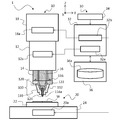
- ⁇ Example 1> 1 is a partial cross-sectional view showing an outline of a friction stir welding apparatus to which a friction stir welding tool according to a first embodiment of the present invention is applied.
- the friction stir welding apparatus 1 to which the friction stir welding tool 100 according to the first embodiment of the present invention is applied includes a main body unit 10, a work transport unit 20, and a control unit 30.
- the main body 10 of the friction stir welding apparatus 1 includes a headstock 12 and a headstock feed device 18.
- the head stock 12 includes a main spindle frame 14 and a rotary main spindle 16 included so as to rotate relative to the main spindle frame 14.
- the spindle feeder 18 moves the spindle stock 12 in the three-axis directions of XYZ.
- a housing 110 of a friction stir welding tool 100 described later is installed at the lower end of the spindle frame 14.
- a stirring pin 120 of the friction stir welding tool 100 is connected to the rotary spindle 16. Thereby, in the friction stir welding tool 100 according to the first embodiment of the present invention, the stirring pin 120 rotates relative to the housing 110.
- the workpiece transport unit 20 includes a processing table 22 on which the workpiece W is placed and supported, and a processing table feeding device 24 that moves the processing table 22 in the XY directions.
- the processing table 22 is provided with a support mechanism (not shown) such as a clamp for fixing and supporting the workpiece W to be joined on the upper surface thereof, and is driven with respect to the friction stir welding tool 100 by driving the processing table feeding device 24. The workpiece W is moved relatively.
- control unit 30 allows the operator to control the numerical control device 32 that controls the movement of the entire friction stir welding apparatus 1 including the headstock 12, the processing table 22, and the like, and the processing conditions in the processing control that the numerical control device 32 executes.
- An interface 34 for inputting and a memory 36 for storing data 36a such as various machining programs and machining conditions are provided.
- the numerical control device 32 includes a rotation control unit 32 a that outputs a rotation command signal for controlling the rotation of the friction stir welding tool 100 to the rotation drive unit 12 a built in the head stock 12 of the main body 10, and the head stock feed device 18. And a feed axis controller 32b that outputs a feed command signal for controlling the movement of the headstock 12 to a feed axis drive unit 18a built in the machine.
- the friction stir welding tool 100 includes a housing 110 attached to the lower end of the spindle frame 14 and a stirring pin 120 attached to the rotating spindle 16.
- the housing 110 is configured by a housing body 112 having a first surface (shoulder surface) 114a that is formed at the upper end with a mounting portion 116 that is installed on the spindle frame 14 and that contacts the work W in a non-rotating state.
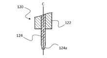
- the agitation pin 120 includes a pin holder 122 attached to the rotation main shaft 16 and a pin body 124 detachably attached to the pin holder 122, and extends along the rotation axis C.
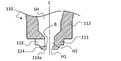
- FIG. 2A to 2C are cross-sectional views showing specific features of the main part of the friction stir welding tool according to the first embodiment of the present invention.
- FIG. 2A shows an outline of the tool tip in use
- FIG. Shows an outline of the vicinity of the tip of the housing
- FIG. 2C shows an outline of the stirring pin accommodated in the housing.
- the friction stir welding tool 100 according to the first embodiment of the present invention is accommodated from the upper end side attached to the spindle frame 14 to the lower end side where the first surface 114a is formed inside the housing 110.
- a hole SH is formed.
- the accommodation hole SH accommodates the stirring pin 120 so as to be relatively rotatable around the rotation axis C with respect to the housing 110, and opens in the first surface 114a. Furthermore, the stirring pin 120 includes, at one end along the rotation axis C, a stirring portion 124a that protrudes from the first surface 114a while being accommodated in the accommodation hole SH and is inserted into the workpiece. Further, the housing 110 is formed with a discharge hole 118 that allows the accommodation hole SH to communicate with the outside of the housing 110.
- the housing 110 has a first surface 114a in contact with the upper surface of the work W at the lower end of the housing main body 112.
- the housing hole SH of the housing body 112 includes a first housing hole H1 and a second housing hole H2 that are connected to each other.
- the 1st accommodation hole H1 is located in the 1st surface 114a side with respect to the 2nd accommodation hole H2, and opens to the 1st surface 114a.
- the second accommodation hole H2 is located on the rotation main shaft 16 side with respect to the first accommodation hole H1.
- the first surface 114a is preferably in contact with the workpiece W in an area smaller than the projected area of the housing 110.
- a reduced diameter portion 113 having a reduced outer diameter is formed as an example at the lower end of the housing main body 112, and a protruding portion 114 that tapers from the lower portion toward the tip is formed.
- the first surface 114a located in the portion functions as a shoulder surface that comes into contact with the workpiece when performing friction stir welding.
- the protruding portion 114 is formed with a first receiving hole H1 connected to the second receiving hole H2, and a part of the pin body 124 of the stirring pin 120 is received.
- the first accommodation hole H1 and the second accommodation hole H2 are set so that the hole diameter is larger than the outer diameter of the pin main body 124 of the agitating pin 120 described later, and the second accommodation hole H2. Is set so that the hole diameter is larger than that of the first accommodation hole H1.
- the housing main body 112 is formed with a discharge hole 118 that communicates the housing hole SH with the outside of the housing main body 112.
- the discharge hole 118 is preferably formed at a position including the boundary B between the first accommodation hole H1 and the second accommodation hole H2. Further, the discharge hole 118 may be formed by additionally processing a hole penetrating inward by drilling or milling.
- the agitation pin 120 includes a pin body 124 having an agitation part 124a at one end and a pin holder 122, which are separated from each other along the rotation axis C with respect to the agitation part 124a. On the other side, it is configured to be attached to the pin holder 122 and is rotatably accommodated in the accommodation hole SH of the housing body 112 as shown in FIG. 2A.
- the pin main body 124 performs friction stir welding by rotating around the rotation axis C and moving relative to the workpiece W in a state where the stirring portion 124a at one end thereof is pushed into the workpiece W.
- the housing 110 is in non-rotating contact with the workpiece W, and the stirring pin 120 is structured to rotate with respect to the housing 110.
- a gap (clearance) G having a predetermined interval is formed.
- FIG. 3 is a cross-sectional view showing an outline when the butt portion of two metal plates is friction stir welded using the friction stir welding tool according to Example 1 of the present invention.
- the stirring pin 120 of the friction stir welding tool 100 is used.
- the agitating portion 124a of the pin main body 124 is rotated around the rotation axis C, for example, in the direction indicated by the rotation direction R in the drawing, and the first portion of the housing main body 112 is placed on the abutting portion of the two workpieces W1 and W2. Push until the surface 114a contacts.
- the first surface 114a of the housing main body 112 contacts the upper surface of the abutting portion of the workpieces W1 and W2 as a shoulder surface, and the agitating portion 124a of the pin main body 124 is inserted into the abutting portion.
- the metal M tends to plastically flow to the upper surface side of the butt portion.
- the surplus metal M overflows to the outside of the shoulder and becomes a “burr” on the surface of the joint.
- a part of the surplus metal M may become “burrs” as in the above case. Most of them enter the second accommodation hole H2 of the accommodation hole SH formed in the housing body 112 through the gap G between the first accommodation hole H1 and the pin body 124 shown in FIG. 2A. .
- the intrusion amount of the surplus metal M passing through the gap G is adjusted by using a housing having a different hole diameter of the first accommodation hole H1 with respect to the shape of the pin body 124 determined by the joining conditions.
- the friction stir welding tool 100 by forming the discharge hole 118 that communicates the second accommodation hole H2 in the accommodation hole SH of the housing main body 112 with the outside, the above-mentioned is described.
- the surplus metal M entering the second accommodation hole H2 is discharged to the outside of the housing body 112.
- the surplus metal M that has entered the housing hole SH is caused by the expansion of the hole diameter of the housing hole SH. Due to the flow away from the rotation axis C and the centrifugal force generated by the rotating operation of the stirring pin 120 during joining, it becomes easy to be discharged to the outside.
- the discharge hole 118 at a position including the boundary B between the first storage hole H1 and the second storage hole H2, surplus metal M stays in the second storage hole H2 and the discharge hole 118. Without being discharged continuously and smoothly to the outside of the housing body 112.
- the surplus metal M is gradually cooled and solidified while passing through the discharge hole 118 and is discharged to the outside as a burr, it does not adhere to the workpiece M and reduce the quality of the surface of the joint portion.
- the discharge hole 118 is formed in the accommodation hole SH along the flow generated by the rotation of the stirring pin 120 by the plastically flowing surplus metal M which is a part of the workpiece W. It may be formed to be discharged from the housing 110 to the outside.
- the first surface 114a, the inner surface of the first housing hole H1, the inner surface of the second housing hole H2 in the housing hole SH, the pin body 124, and the like are compatible with the material constituting the workpiece W. It is good to form the film (not shown) which consists of a raw material with low property. Thereby, adhesion with the housing 110 and the stirring pin 120 of the surplus metal M is reduced.
- a gas flow supply mechanism (not shown) that supplies a gas flow F to the accommodation hole SH of the housing 110 is further provided on the spindle frame 14 of the headstock 12 to which the housing 110 is attached. You may comprise. As a result, the housing 110 and the agitation pin 120 being joined are cooled, and the surplus metal M that enters the accommodation hole SH is also cooled to facilitate discharge to the outside.
- the friction stir welding tool 100 projects the pin body 124 that rotates relative to the housing body from the first housing hole H1 of the housing body 112 including the first surface 114a.
- the housing body 112 is provided with the discharge hole 118 that allows the housing hole SH to communicate with the outside, so that the gap G between the first housing hole H1 and the pin body 124 is removed. Even if the surplus metal M that is a part of the workpiece W enters, it can be efficiently discharged to the outside.
- the pin main body 124 and the surplus metal M do not excessively generate heat by friction in the accommodation hole SH formed in the housing 110, a decrease in strength, breakage, or the like of the pin main body 124 can be suppressed as a result. .
- the agitation pin 120 is composed of the pin body 124 and the pin holder 122 separately, only the pin body 124 having the agitation portion 124a that always contacts the workpiece W during the friction agitation welding is replaced as a consumable item. By doing so, breakage of the stirring pin 120 itself can be suppressed. Furthermore, since only the pin body 124 can be replaced as a consumable item, the running cost as a friction stir welding tool can be reduced.
- Example 2 Next, the outline of the friction stir welding tool according to Example 2 of the present invention will be described with reference to FIGS. 4 and 5.
- the configuration of the friction stir welding apparatus to which the friction stir welding tool according to the second embodiment is applied is the same as that of the first embodiment except for the friction stir welding tool including the detachable shoulder. The re-explanation here is omitted.
- FIG. 4A and 4B are cross-sectional views showing specific features of the main part of the friction stir welding tool according to the second embodiment of the present invention.
- FIG. 4A shows an outline of the tool tip in use
- FIG. Shows the outline of the mounting structure of the housing body and the shoulder.
- the friction stir welding tool 200 according to the second embodiment of the present invention includes a housing 210 installed on the spindle frame 14 shown in FIG. 1 and a stirring pin 220 connected to the rotary spindle 16. Composed.
- the housing 210 is configured separately from the housing main body 212 and a shoulder 230 that is detachably attached to the lower end of the housing main body 212.
- the stirring pin 220 includes a pin body 224 that is detachably attached and extends along the rotation axis C.
- the housing main body 212 of the housing 210 has a lower end opened and a holding portion 217 for holding a shoulder 230 described later.
- the holding portion 217 of the housing main body 212 includes a holding surface 217 a that holds the held surface 232 a of the shoulder 230, and a contact surface 217 b that contacts the positioning surface 232 b formed at the upper end of the shoulder 230.
- a female screw is formed.
- the shoulder 230 includes an attachment portion 232 formed with a positioning surface 232b that contacts the contact surface 217b of the housing body 212, a reduced diameter portion 233 that continues from the attachment portion 232 in the height direction, and a reduced diameter portion 233. Further, a projecting portion 234 that tapers toward the tip is integrally formed. And the 1st surface 234a located in the edge part of the protrusion part 234 functions as a shoulder surface which contacts a workpiece
- the outer shape of the attachment portion 232 is an attachment structure having a shape corresponding to the holding surface 217a of the housing body 212 described above.
- the held surface 232a of the attachment portion 232 is formed with a male screw, for example.
- a second accommodation hole H ⁇ b> 2 that constitutes a part of the accommodation hole SH of the housing 210 is formed inside the shoulder 230.
- the projecting portion 234 is formed with a first housing hole H1 that is connected to the second housing hole H2 and opens in the first surface 234a, and a part of the pin body 224 of the stirring pin 220 is housed.
- the first accommodation hole H1 and the second accommodation hole H2 are set to have a larger diameter than the outer diameter of the pin body 224, and the second accommodation hole H2 is The hole diameter is set to be larger than that of the first accommodation hole H1.
- the shoulder 230 is formed with a discharge hole 238 that allows the accommodation hole SH to communicate with the outside of the shoulder 230.
- the discharge hole 238 is preferably formed at a position including at least the boundary B between the first accommodation hole H1 and the second accommodation hole H2.
- FIG. 5A to 5C are diagrams for explaining a specific configuration of the shoulder shown in FIG. 4B, in which FIG. 5A shows a side view, FIG. 5B shows a bottom view, and FIG. 5C shows a top view. .
- the mounting portion 232, the reduced diameter portion 233, and the protruding portion 234 described above are integrally formed, and the lower end surface of the protruding portion 234 is the first surface 234a.
- a male screw is formed on the held surface 232 a of the mounting portion 232, and a positioning surface 232 b that contacts the contact surface 217 b of the housing body 212 is formed at the upper end of the mounting portion 232.
- the shoulder 230 is formed with a discharge hole 238 that allows the accommodation hole SH and the outside of the shoulder 230 to communicate with each other in a manner in which a part thereof is cut away.
- the discharge hole 238 is configured so that the plastically flowing surplus metal M that is a part of the workpiece W is discharged from the second housing hole H2 to the outside of the shoulder 230 along the flow generated by the rotation of the stirring pin 220. It may be formed.
- the shoulder 230 includes a connection position P1 where the inner peripheral surface 238a of the discharge hole 238 and the inner peripheral surface H2a of the second accommodation hole H2 are connected in the rotation direction R of the stirring pin 220. Is formed so as to include the tangential direction T1 of the inner periphery of the second accommodation hole H2 at the connection position P1. Thereby, the surplus metal M can be continuously and smoothly discharged
- the outer surface of the reduced diameter portion 233 has a prismatic shape (in the case of FIG. 5B, a hexagonal prism) as an example. This makes it easy to grip the mounting portion 232 of the shoulder 230 when screwed into the holding portion 217 of the housing body 212.
- the friction stir welding tool 200 has a structure in which the housing 210 is detachably attached to the tip of the housing main body 212 in addition to the effects obtained in the first embodiment.
- the housing 210 is detachably attached to the tip of the housing main body 212 in addition to the effects obtained in the first embodiment.
- the first surface 234a that is always in contact with the workpiece W during friction stir welding is damaged due to wear or the like, only the shoulder 230 can be replaced as a consumable, so the running cost as a friction stir welding tool can be reduced. Can be reduced.
- the penetration amount of the surplus metal M into the accommodation hole SH can be adjusted by using a housing having a different hole diameter of the first accommodation hole H1 with respect to the shape of the pin body 224 determined by the joining conditions.
- Example 3 Next, the outline of the friction stir welding tool according to Example 3 of the present invention will be described with reference to FIG.
- the configuration of the friction stir welding apparatus to which the friction stir welding tool according to the third embodiment is applied is the same as that of the first embodiment except for the friction stir welding tool including the detachable shoulder. The re-explanation here is omitted.
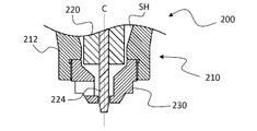
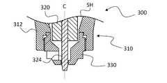
- FIG. 6A and 6B are cross-sectional views showing specific features of the main part of the friction stir welding tool according to the third embodiment of the present invention.
- FIG. 6A shows an outline of the tool tip in use
- FIG. Shows the outline of the mounting structure of the housing body and the shoulder.
- the friction stir welding tool 300 according to the third embodiment of the present invention includes a housing 310 installed on the spindle frame 14 shown in FIG. 1 and a stirring pin 320 connected to the rotary spindle 16. Composed.
- the housing 310 has a housing main body 312 and a shoulder 330 that is detachably attached to the lower end of the housing main body 312.
- the housing 310 has a shoulder 330 attached to the housing main body 312.
- the housing hole SH is formed, and the stirring pin 320 is rotatably accommodated.
- the housing main body 312 of the housing 310 has a lower end opened and a holding portion 317 for holding a shoulder 330 described later.
- the holding portion 317 of the housing body 312 includes a holding surface 317 a that holds the held surface 332 a of the shoulder 330, an upper contact surface 317 b that contacts an upper positioning surface 332 b that determines the position of the shoulder 330 in the rotation axis C direction, and a shoulder
- a female screw is formed on the holding surface 317a.
- the side contact surface 317c contacts the side positioning surface 332c that determines the radial position of the rotation axis C of 330.
- the shoulder 330 includes a mounting portion 332 in which a held surface 332a, an upper positioning surface 332b, and a side positioning surface 332c are formed, a reduced diameter portion 333 continuous in the height direction from the mounting portion 332, and a reduced diameter portion 333. And a projecting portion 334 that is tapered toward the tip. And the 1st surface 334a located in the edge part of the protrusion part 334 functions as a shoulder surface which contacts a workpiece
- a second accommodation hole H2 constituting a part of the accommodation hole SH of the housing 310 is formed inside the shoulder 330, and the second accommodation hole H2 and the outside are connected to the protruding portion 334.
- a first accommodation hole H1 is formed.
- the first housing hole H1 and the second housing hole H2 have a hole diameter larger than the outer diameter of the pin body 324, and the second housing hole H2 Is set so that the hole diameter is larger than that of the first accommodation hole H1.
- the outer shape of the attachment portion 332 is an attachment structure having a shape corresponding to the holding portion 317 of the housing main body 312 described above.
- the held surface 332a of the attachment portion 332 is formed with a male screw, for example.
- the upper positioning surface 332 b formed at the upper end of the mounting portion 332 contacts the upper contact surface 317 b of the housing body 312 and determines the position of the shoulder 330 in the direction of the rotation axis C.
- the side positioning surface 332 c formed on the side surface of the upper portion of the attachment portion 332 contacts the side contact surface 317 c of the housing body 312 and determines the radial position of the rotation axis C of the shoulder 330.
- the shoulder 330 is formed with a discharge hole 338 that allows the accommodation hole SH and the outside of the shoulder 330 to communicate with each other.
- the discharge hole 338 is preferably formed at a position including at least the boundary B between the second accommodation hole H2 and the first accommodation hole H1. Further, the discharge hole 338 is formed so that the plastically flowing surplus metal that is a part of the work is discharged from the second accommodation hole H2 to the outside of the shoulder 330 along the flow generated by the rotation of the stirring pin 320. May be.
- the shoulder 330 contacts the upper contact surface 317b of the housing body 312 and the side contact surface 317c of the housing body 312. And a side positioning surface 332c that comes into contact with.
- the shoulder 330 is attached to the housing main body 312 by forming the side positioning surface 332c that contacts the side abutting surface 317c of the housing main body 312 with a fitting structure.
- the shoulder 330 When mounting, the shoulder 330 is accurately positioned with respect to the housing main body 312 in the direction of the rotation axis C and the radial direction of the rotation axis C, and even when the shoulder 330 is replaced, it is easily substantially the same before and after replacement. Bonding quality can be maintained.
- Example 4 Next, the outline of the friction stir welding tool according to Example 4 of the present invention will be described with reference to FIG.
- the configuration of the friction stir welding apparatus to which the friction stir welding tool according to the fourth embodiment is applied is the same as that of the first embodiment except for the friction stir welding tool including the detachable shoulder. The re-explanation here is omitted.
- FIG. 7A and 7B are cross-sectional views showing specific features of the main part of the friction stir welding tool according to Example 4 of the present invention.
- FIG. 7A shows an outline of the tool tip in use
- FIG. Shows the outline of the mounting structure of the housing body and the shoulder.
- a friction stir welding tool 400 according to Embodiment 4 of the present invention includes a housing 410 attached to the spindle frame 14 shown in FIG. 1, a stirring pin 420 connected to the rotating spindle 16, Consists of.
- the housing 410 includes a housing body 412 and a shoulder 430 that is detachably attached to the lower end of the housing body 412, and the shoulder 430 is attached to the housing body 412.
- an accommodation hole SH is formed inside thereof, and the agitation pin 420 is accommodated rotatably.
- the housing main body 412 of the housing 410 is formed with a holding portion 417 for holding the shoulder 430 on the inner surface thereof while the lower end thereof is opened as in the third embodiment.
- the shoulder 430 includes an attachment portion 432 attached to the housing body 412, a reduced diameter portion 433 that continues in the height direction from the attachment portion 432, and a further reduction diameter portion 433 toward the tip.
- a tapered projecting portion 434 is integrally formed, and the first surface 434a located at the end of the projecting portion 434 functions as a shoulder surface that comes into contact with the workpiece when performing friction stir welding.
- a second housing hole H2 constituting a part of the housing hole SH of the housing 410 is formed inside the shoulder 430, and the projecting portion 434 is connected to the second housing hole H2, A first accommodation hole H1 that opens to one surface 434a is formed.
- the first accommodation hole H1 and the second accommodation hole H2 have a hole diameter larger than the outer diameter of the pin body 424
- the housing hole H2 is set so that the hole diameter is larger than that of the first housing hole H1.
- the lower end portion of the second accommodation hole H2 constituting a part of the accommodation hole SH is smoothly directed toward the boundary B with the first accommodation hole H1.
- a curved surface 433a having a reduced diameter is formed, and even if the surplus metal M enters the accommodation hole SH, it does not stagnate below the second accommodation hole H2.
- the shoulder 430 is formed with a discharge hole 438 that allows the accommodation hole SH to communicate with the outside of the shoulder 430.
- the discharge hole 438 is preferably formed at a position including at least the boundary B between the first accommodation hole H1 and the second accommodation hole H2. Further, the discharge hole 438 is formed so that the plastically flowing surplus metal M that is a part of the work is discharged from the second receiving hole H2 to the outside of the shoulder 430 along the flow generated by the rotation of the stirring pin 420. May be.
- the friction stir welding tool 400 has the second accommodation hole that constitutes a part of the accommodation hole SH of the shoulder 430 in addition to the effects obtained in the first to third embodiments.
- a curved surface 433a that is smoothly reduced in diameter toward the boundary B with the first accommodation hole H1 is formed at the lower end of H2, so that it passes through the gap G between the pin body 424 and the first accommodation hole H1 to the inside. It can suppress that the excess metal M which penetrate
- FIG. 8 is a cross-sectional view showing an outline of the tool tip when the friction stir welding tool according to the fifth embodiment of the present invention is used.
- the configuration of the friction stir welding apparatus to which the friction stir welding tool according to the fifth embodiment is applied is the same as that of the first embodiment except for the friction stir welding tool including the detachable shoulder. The re-explanation here is omitted.
- the friction stir welding tool 500 includes a housing 510 installed on the spindle frame 14 shown in FIG. 1 and a stirring pin 520 connected to the rotating spindle 16. Composed.
- the housing 510 includes a housing main body 512 and a shoulder 530 that is detachably attached to the lower end of the housing main body 512.
- the housing 510 has a shoulder 530. In the state where is attached, the accommodation hole SH is formed inside thereof, and the stirring pin 520 is rotatably accommodated.
- a substantially tapered second accommodation hole H2 that is reduced in diameter toward the lower portion is formed inside the shoulder 530.
- the shoulder 530 is formed with a discharge hole 538 that communicates the second accommodation hole H ⁇ b> 2 and the outside of the shoulder 530.
- the shoulder 530 including the first surface 534a is formed of a metal material such as steel.
- the processing of the outer surface and the inner surface of the shoulder 530 is often performed by machining such as turning, but the shoulder 530 according to the modification shown in FIG. 8 has a large tapered inner surface. Can be turned.
- the discharge hole 538 is substantially tapered from the second accommodation hole H2 to the shoulder 530.
- surplus metal see symbol M in FIG. 3
- the shape of the shoulder 530 suitable for machining, the number of machining steps can be reduced, and the shoulder 530 itself can be reduced in weight.
- Example 6 Next, the outline of the friction stir welding tool according to Example 6 of the present invention will be described with reference to FIG. In the following description, only the difference in configuration from the friction stir welding tool shown in the first to fifth embodiments will be described, and the same reference numerals as those in the second embodiment are used for other common configurations. The description will be made and the illustration is omitted.
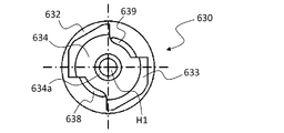
- FIG. 9A to 9C are views for explaining a specific configuration of a shoulder applied to a friction stir welding tool according to a sixth embodiment of the present invention.
- FIG. 9A is a side view
- FIG. 9B is a bottom view
- FIG. 9C shows a top view, respectively.
- the attachment portion 632, the reduced diameter portion 633, and the protruding portion 634 are integrally formed as in the case of the third embodiment, and the end portion of the protruding portion 634 is formed.
- the first surface 634a located on the surface functions as a shoulder surface that comes into contact with the workpiece when performing friction stir welding.
- the held surface 632 a of the mounting portion 632 is formed with a male screw, and a positioning surface 632 b that contacts the contact surface 217 b of the housing body 212 is formed at the upper end of the upper end portion 632.
- the shoulder 630 is formed with two discharge holes 638 and 639 that communicate the second housing hole H ⁇ b> 2 and the outside of the shoulder 630 in a manner in which a part thereof is cut away. Yes.
- the discharge holes 638 and 639 are formed on the outside of the shoulder 630 from the accommodation hole SH along the flow generated by the rotation of the stirring pin 220 by the plastically flowing surplus metal (see symbol M in FIG. 3) that is a part of the workpiece W. You may form so that it may be discharged.
- the shoulder 630 includes an inner peripheral surface 638a of the discharge hole 638 and an inner peripheral surface H2a of the second accommodation hole H2 in the rotation direction R of the stirring pin. Includes a connection position P1 to which the At this time, the discharge hole 638 is formed so as to include the tangential direction T1 of the inner periphery of the second accommodation hole H2 at the connection position P1.
- the shoulder 630 includes a connection position P2 where the inner peripheral surface 639a of the discharge hole 639 and the inner peripheral surface H2a of the second accommodation hole H2 are connected in the rotation direction R of the stirring pin.
- the discharge hole 639 is formed so as to include the tangential direction T2 of the inner periphery of the second accommodation hole H2 at the connection position P2.
- the two discharge holes 638 and 639 are preferably arranged so as to face each other in the circumferential direction of the second accommodation hole H2, that is, at equal intervals. As a result, the rigidity of the entire shoulder 630 to be cut out can be balanced, and the excess metal can be discharged efficiently.
- the friction stir welding tool according to the sixth embodiment of the present invention has the discharge holes 638 and 639 formed in the shoulder 630 in addition to the effects obtained in the first to fifth embodiments. Efficiency can be further increased. As a result, excessive frictional heat generation between the stirring pin and the surplus metal can be further suppressed, and a reduction in strength or breakage of the stirring pin can be suppressed.
- friction stir welding tool and the friction stir welding apparatus in Examples 1 to 6 are exemplified in the continuous joining of members, the use for the point joining is not excluded.
- the housing may be further provided with a structure for receiving the surplus metal so that the surplus metal discharged from the discharge hole does not fall on the work upper surface.
- the shoulder surface first surface
- the shoulder surface has not only a flat shape but also a concave shape or a convex shape.
- a cross groove, a spiral groove, or the like may be formed on the shoulder surface.
- the case where the housing and the shoulder are screwed is illustrated.
- other attachment structures such as a suction structure using a magnetic force or a vacuum pressure or a chucking structure using a claw or the like are applied. May be.
- the case where two holes are formed as a plurality of discharge holes is illustrated. However, in consideration of the overall rigidity of the shoulder and the discharge efficiency of surplus metal, three or more discharge holes are formed. You may comprise as follows. Further, in the sixth embodiment, the case where a plurality of discharge holes are formed in the detachable shoulder shown in the second to fifth embodiments is exemplified. However, such a plurality of discharge holes are formed in the housing main body shown in the first embodiment. You may comprise so that it may form.
- Friction stir welding apparatus 10 Main-body part 12 Main stand 14 Main spindle frame 16 Rotation main spindle 18 Main spindle feed apparatus 20 Work conveyance part 22 Processing table 24 Processing table feed apparatus 30 Control part 32 Numerical control apparatus 34 Interface 36 Memory 100, 200, 300 , 400, 500 Friction stir welding tool 110, 210, 310, 410, 510 Housing 112, 212, 312, 412, 512 Housing body 113 Reduced diameter portion 114 Projection portion 114a First surface 118, 238, 338, 438, 538, 638, 639 Discharge holes 120, 220, 320, 420, 520 Stirring pins 122, 222 Pin holders 124, 224, 324, 424, 524 Pin bodies 124a, 224a Stirring portions 217, 317, 417 Holding portions 230, 330, 430 530 , 630 Shoulder 232, 332, 432, 632 Mounting portion 233, 333, 433, 633 Reduced diameter portion
Landscapes
- Engineering & Computer Science (AREA)
- Mechanical Engineering (AREA)
- Pressure Welding/Diffusion-Bonding (AREA)
Abstract
本発明は、摩擦攪拌接合用工具及びこれを適用した摩擦攪拌接合装置である。本発明による摩擦攪拌接合用工具は、回転軸を有する攪拌ピンと、第一の面を有するハウジングと、を備え、ハウジングは、上記攪拌ピンを相対的に前記回転軸周りで回転可能に収容し、上記第一の面に開口する収容穴を含み、攪拌ピンは、その回転軸に沿った一端に、上記収容穴に収容された状態で第一の面から突出し、ワークに対して挿入される攪拌部を含み、ハウジングには、上記収容穴から前記ハウジングの外部と連通する排出穴が形成されている。
Description
本発明は、摩擦攪拌接合用工具及びこれを適用した摩擦攪拌接合装置に関する。
別体で構成されたピンとショルダとからなる回転工具を回転ヘッドに取り付けて、ピンをショルダに対し相対的に回転させつつワーク内に挿入し、ワークと回転工具との摩擦熱によりワークを加熱して塑性流動を生じさせて接合する、いわゆる摩擦攪拌接合技術が知られている。こうした摩擦攪拌接合によれば、ワークを溶融させることなく接合することにより、ワークへの過剰な入熱が低減できるため、ワークの材質の低下や接合後の変形が抑制できる。
このような摩擦攪拌接合技術の1つとして、例えば特許文献1及び特許文献2に開示された摩擦攪拌接合装置が知られている。このような接合装置は、2つの部材の突合せ部に対する連続的な接合や、重ね合わせ部に対する点接合(スポット接合)等に適用されている。
特許文献1及び特許文献2に開示された接合装置では、ピンとショルダ部材との間に入り込んだ材料カスとピンとの間で摩擦熱が発生し、ピンが過剰に熱せられて強度が低下したり、あるいは最終的にピンの破損を招く等、工具寿命の低下の一因となる。
本発明は、以上のような状況に鑑みてなされたものであって、その目的は、ピンとショルダとを別体に構成した場合に、ピンとショルダとの間の隙間からワークの一部が侵入した場合であっても、ピンの強度低下や破損等を抑制できる摩擦攪拌接合用工具及びこれを用いた摩擦攪拌接合装置を提供することにある。
本発明の第一の側面によれば、摩擦攪拌接合用工具は、回転軸を有する攪拌ピンと、第一の面を有するハウジングと、を備え、前記ハウジングは、攪拌ピンを相対的に回転軸周りで回転可能に収容し、第一の面に開口する収容穴を含み、攪拌ピンは、回転軸に沿った一端に、収容穴に収容された状態で第一の面から突出し、ワークに対して挿入される攪拌部を含み、ハウジングには、収容穴からハウジングの外部と連通する排出穴が形成されていることを特徴とする。
また、本発明の第二の側面によれば、摩擦攪拌接合装置は、回転主軸を含む主軸台と、主軸台に取り付けられる上記の摩擦攪拌接合用工具と、ワークを保持する加工テーブルと、主軸台及び加工テーブルの相対的な動きを制御する数値制御装置と、を備えることを特徴とする。
かかる発明によれば、摩擦攪拌接合用工具のハウジングにおいて、攪拌ピンを収容する収容穴とハウジングの外部とを連通する排出穴を備えることにより、攪拌ピンとハウジングの収容穴との隙間から侵入したワークを上記排出穴から排出できるため、攪拌ピンの強度低下や破損等を抑制できる。
摩擦攪拌接合技術の1つとして、ピンとショルダとが別体で構成された摩擦攪拌接合用工具を回転ヘッドに取り付け、ショルダをワークに接触させた状態で、ピンをショルダに対して回転させつつワークの内部に挿入して摩擦攪拌接合する接合装置が知られている(例えば特許文献1参照)。このような接合装置は、接合に必要な摩擦発熱をピンの回転のみで充足し得るという利点があり、2つの部材の突合せ部に対する連続的な接合や、重ね合わせ部に対する点接合(スポット接合)等に適用されている。
このような接合装置では、摩擦攪拌接合用工具がピンとショルダを含むハウジングとが別体で構成されているため、ピンとハウジングとの間には所定のクリアランス(間隙)が存在することは、構造上避けられない。このため、摩擦攪拌接合時に塑性流動したワークの材料の一部が、上記クリアランスを通って工具の内部に侵入することとなる。
このような場合、接合後にワークが冷えると、工具の内部に侵入したワークの一部も冷えて固まるため、ピンとハウジングとの間でワークが凝着してしまい、工具の繰り返しの使用が困難となることがあった。また、侵入したワークは外部に排出されず工具の内部に留まるため、一定のワークが侵入した後は塑性流動したワークの一部は、ショルダとワークの間から漏れ出し、ワークの上面に固着して、接合部表面の品質を低下させる。
このような事象を解消するために、プローブ(ピン)とショルダ部材とを別体に構成したいわゆる複動式回転工具を用いた摩擦攪拌点接合装置(例えば特許文献2参照)において、ショルダ部材の側壁に複数の排出孔を形成するとともに、プローブ外周にも複数の突起物を形成し、摩擦攪拌点接合時にプローブとショルダ部材との間に侵入した材料カスを上記突起物で細かく分断した後、排出孔から排出するようにした改良がなされている。これにより、点接合においては、工具の内部に侵入した材料カスを効率的に外部に排出して、プローブとショルダ部材との凝着を回避することが可能となる。
しかしながら、2つのワークの突合せ部に沿って連続的に接合を行う摩擦攪拌接合装置の場合には、接合の最初から最後まで、すなわちピンの先端が突合せ部に押し込まれてから抜き取られるまでの間に、ピンとショルダとの隙間から連続的にワークの一部がハウジングの内部に侵入することなるため、ハウジングの内部には多量のワークの一部が滞留してしまうことになる。このとき、工具を構成するピンは、連続的に摩擦攪拌接合を行っている間に常に回転しているため、ハウジングの内部に滞留したワークの一部がピンと接触する場合、回転するピンとワークの一部との間で摩擦熱が発生し、ピンが過剰に熱せられて強度が低下したり、あるいは最終的にピンの破損を招く等、工具寿命の低下の一因となる。
一方、上記の摩擦攪拌点接合装置では、プローブとショルダ部材との間に入り込んだ材料カスを外部に排出することが可能であるが、点接合は基本的にワークの接合部表面に沿う工具の移動がなく、また接合の1箇所あたりの接合時間はごく短時間であるため、1回ごとに工具内に侵入する材料カスの量はそれほど多くならない。このため、摩擦攪拌店接合装置においては、侵入した材料カスをプローブに形成された突起物で分断することで、少量の小片として外部に排出することができる。
しかしながら、上記のような排出孔を形成した工具は、プローブとショルダ部材との間に敢えて材料カスを滞留させる空間を形成して、当該空間内においてプローブに形成した突起物で材料カスを細かく分断するように構成されているため、仮にこのような工具を用いて連続的な摩擦攪拌接合を行ったとしても、連続的に侵入する材料カスとプローブとが接触して摩擦熱を発生することに変わりはなく、その摩擦熱のためにプローブの強度低下や破損等による工具寿命の低下は避けられないという問題を内在していた。
そこで、実施形態における摩擦攪拌接合用工具は、ハウジングに、攪拌ピンを収容する収容穴とハウジングの外部とを連通する排出穴を備える。このような排出穴を備えることにより、侵入した材料カスを連続的に排出できるため、プローブの強度低下や破損等を抑制し、工具寿命の低下を避けることができる。なお、発明者によって認識された事項の記述は、実施形態における摩擦攪拌接合用工具についての理解を深めるために参考として記載されたものであり、公知技術を示すものではない。
<実施例1>
図1は、本発明の実施例1による摩擦攪拌接合用工具を適用した摩擦攪拌接合装置の概要を示す部分断面図である。図1に示すように、本発明の実施例1による摩擦攪拌接合用工具100を適用した摩擦攪拌接合装置1は、本体部10と、ワーク搬送部20と、制御部30と、を備える。
図1は、本発明の実施例1による摩擦攪拌接合用工具を適用した摩擦攪拌接合装置の概要を示す部分断面図である。図1に示すように、本発明の実施例1による摩擦攪拌接合用工具100を適用した摩擦攪拌接合装置1は、本体部10と、ワーク搬送部20と、制御部30と、を備える。
摩擦攪拌接合装置1の本体部10は、主軸台12と、主軸台送り装置18とにより、構成される。主軸台12は、主軸フレーム14と、主軸フレーム14に対して相対的に回転するよう内包された回転主軸16と、を備える。主軸送り装置18は、主軸台12をXYZの3軸方向に移動させる。主軸フレーム14の下端には、後述する摩擦攪拌接合用工具100のハウジング110が据え付けられる。
一方、回転主軸16には、同じく摩擦攪拌接合用工具100の攪拌ピン120が連結される。これにより、本発明の実施例1による摩擦攪拌接合用工具100において、ハウジング110に対して攪拌ピン120が相対的に回転する。
ワーク搬送部20は、ワークWを載置して支持する加工テーブル22と、当該加工テーブル22をXY方向に移動させる加工テーブル送り装置24と、により構成される。加工テーブル22は、その上面に、接合されるワークWを固定支持する例えばクランプ等の支持機構(図示せず)を備えており、加工テーブル送り装置24の駆動により摩擦攪拌接合用工具100に対してワークWを相対的に移動させる。
制御部30は、例えば、主軸台12や加工テーブル22等を含む摩擦攪拌接合装置1全体の動きを制御する数値制御装置32と、数値制御装置32が実行する加工制御における加工条件等をオペレータが入力するためのインターフェース34と、各種加工プログラムや加工条件等のデータ36aを記憶するメモリ36と、を備えている。数値制御装置32は、本体部10の主軸台12に内蔵される回転駆動部12aに摩擦攪拌接合用工具100の回転を制御する回転指令信号を出力する回転制御部32aと、主軸台送り装置18に内蔵される送り軸駆動部18aに主軸台12の移動を制御する送り指令信号を出力する送り軸制御部32bと、を有する。これにより、主軸台12及び加工テーブル22の相対的な動きや、接合中における摩擦攪拌接合用工具100の回転数、ワークWへの工具挿入深さ等が制御される。
本発明の実施例1による摩擦攪拌接合用工具100は、主軸フレーム14の下端に取り付けられるハウジング110と、回転主軸16に取り付けられる攪拌ピン120と、を含む。ハウジング110は、上端に主軸フレーム14に据え付けられる据付部116が形成され、下端にワークWに対して非回転の状態で接触する第一の面(ショルダ面)114aを有するハウジング本体112により構成されている。一方、攪拌ピン120は、回転主軸16に取り付けられるピンホルダ122と、当該ピンホルダ122に着脱自在に取り付けられるピン本体124とで構成され、回転軸Cに沿って延伸している。
図2A乃至図2Cは、本発明の実施例1による摩擦攪拌接合用工具の要部における具体的な特徴を示す断面図であって、図2Aは使用時の工具先端の概要を示し、図2Bはハウジングの先端近傍の概要を示し、図2Cはハウジングに収容される攪拌ピンの概要を示している。図2Aに示すように、本発明の実施例1による摩擦攪拌接合用工具100は、ハウジング110の内側において、主軸フレーム14に取り付けられる上端側から第一の面114aが形成された下端側にわたって収容穴SHが形成されている。
この収容穴SHは、攪拌ピン120をハウジング110に対して回転軸C周りで相対的に回転可能に収容し、第一の面114aに開口する。さらに、攪拌ピン120は、回転軸Cに沿った一端に、収容穴SHに収容された状態で第一の面114aから突出し、ワークに対して挿入される攪拌部124aを含む。また、ハウジング110には、収容穴SHとハウジング110の外部とを連通する排出穴118が形成されている。
図2Bに示すように、ハウジング110は、ハウジング本体112の下端にワークWの上面と接触する第一の面114aが形成されている。また、ハウジング本体112の収容穴SHは、互いに接続された第一の収容穴H1と、第二の収容穴H2と、を含む。第一の収容穴H1は、第二の収容穴H2に対して第一の面114a側に位置し、第一の面114aに開口する。第二の収容穴H2は、第一の収容穴H1に対して回転主軸16側に位置する。
ここで、第一の面114aは、ワークWに対してハウジング110の投影面積より小さい面積で接触するのが好ましい。このため、ハウジング本体112の下端には、その一例として、外径が縮小した縮径部113が形成されており、さらにその下部から先端に向けて先細となる突出部114が形成され、その端部に位置する第一の面114aが、摩擦攪拌接合を行う際にワークと接触するショルダ面として機能する。
また、突出部114には第二の収容穴H2と接続する第一の収容穴H1が形成されており、攪拌ピン120のピン本体124の一部が収容される。ここで、一例として、第一の収容穴H1及び第二の収容穴H2は、後述する攪拌ピン120のピン本体124の外径より穴径が大きくなるように設定され、第二の収容穴H2は、第一の収容穴H1よりも穴径が大きくなるように設定されている。
一方、本発明の実施例1による摩擦攪拌接合用工具100の特徴として、ハウジング本体112には、収容穴SHからハウジング本体112の外部とを連通する排出穴118が形成されている。ここで、排出穴118は、第一の収容穴H1と第二の収容穴H2との境界Bを含む位置に形成されるのが好ましい。また、排出穴118は、ドリル加工やミーリング加工で内側に貫通する穴を追加的に加工することで形成されてもよい。
図2Cに示すように、攪拌ピン120は、一端に攪拌部124aを有するピン本体124と、ピンホルダ122と、を別体に構成し、ピン本体124が攪拌部124aに対して回転軸Cに沿った反対側でピンホルダ122に取り付けられた状態で構成され、図2Aに示すように、ハウジング本体112の収容穴SHに回転自在に収容される。ピン本体124は、回転軸C周りに回転しつつその一端の攪拌部124aがワークWに押し込まれた状態でワークWと相対的に移動することにより、摩擦攪拌接合を行う。このとき、ハウジング110はワークWに対して非回転で接触し、攪拌ピン120はハウジング110に対して回転する構造となるため、第一の収容穴H1の内面とピン本体124の外面との間には、所定の間隔の間隙(クリアランス)Gが形成される。
図3は、本発明の実施例1による摩擦攪拌接合用工具を用いて2枚の金属板の突合せ部を摩擦攪拌接合したときの概要を示す断面図である。図3に示すように、加工テーブル22上に固定支持された2枚の金属板からなるワークW1、W2の端面どうしを突合せて摩擦攪拌接合する場合、摩擦攪拌接合用工具100の攪拌ピン120を、回転軸C周りに例えば図示上の回転方向Rに示す方向に回転させつつ、ピン本体124の攪拌部124aを上記した2枚のワークW1、W2の突合せ部に、ハウジング本体112の第一の面114aが接触するまで押し込む。この状態を維持しつつ図示上紙面に対して直交する方向、すなわちワークW1、W2の突合せ部の表面に沿って工具あるいはワークを相対的に移動させると、移動後の突合せ部に摩擦攪拌接合された接合部Jが形成される。
このとき、ワークW1、W2の突合せ部の上面にハウジング本体112の第一の面114aがショルダ面として接触するとともに、突合せ部にはピン本体124の攪拌部124aが挿入される。このため、摩擦攪拌接合の際に摩擦熱で軟化した材料のうち、上記ハウジング本体112のワークW1、W2に沈み込んだ部分や攪拌部124aの突合せ部に挿入された部分の体積に対応する余剰金属Mが、突合せ部の上面側に塑性流動しようとする。ここで、一般的なピンとショルダとが一体である接合用工具を用いた場合は、上記余剰金属Mはショルダの外側に溢れ出て接合部表面の「バリ」となる。
これに対して、ピンとショルダとが別体で構成された本発明のような摩擦攪拌接合用工具100では、余剰金属Mの一部は上記の場合と同様に「バリ」となることもあるが、その多くは図2Aに示した第一の収容穴H1とピン本体124との間隙Gを通って、ハウジング本体112の内部に形成された収容穴SHの第二の収容穴H2内に侵入する。この間隙Gを通る余剰金属Mの侵入量は、接合条件により決定されるピン本体124の形状に対して、異なる第一の収容穴H1の穴径を有するハウジングを用いることにより調整される。
ここで、本発明の実施例1による摩擦攪拌接合用工具100においては、ハウジング本体112の収容穴SHにおける第二の収容穴H2と外部とを連通する排出穴118を形成することにより、上述のとおり第二の収容穴H2に侵入してくる余剰金属Mを、ハウジング本体112の外部に排出するように構成する。これにより、連続的な摩擦攪拌接合の接合中に、摩擦攪拌接合用工具100のハウジング110の収容穴SHの内部に定常的にワークW1、W2の一部である余剰金属Mが侵入したとしても、収容穴SH(特に第二の収容穴H2)にこれらの余剰金属Mが滞留することがないため、攪拌ピン120のピン本体124と余剰金属Mとの間での摩擦発熱を抑制することができる。
さらに、第一の収容穴H1の穴径より第二の収容穴H2の穴径を大きく設定しておくことで、収容穴SHに侵入した余剰金属Mは、収容穴SHの穴径の拡大による回転軸Cから離れる方向に向かう流れと、接合中の攪拌ピン120の回転動作で生じる遠心力により、外部に排出されやすくなる。ここで、排出穴118を第一の収容穴H1と第二の収容穴H2との境界Bを含む位置に形成することで、余剰金属Mが第二の収容穴H2及び排出穴118で滞留することなく、ハウジング本体112の外部へ連続的かつ円滑に排出される。
また、余剰金属Mは、排出穴118を通る間に徐々に冷却され固化された状態でバリとして外部に排出されるため、ワークMに固着して接合部表面の品質を低くすることがない。さらに、より連続的かつ円滑に余剰金属Mを排出するために、排出穴118は、ワークWの一部である塑性流動した余剰金属Mが攪拌ピン120の回転により生じる流れに沿って収容穴SHからハウジング110の外部に排出されるように形成してもよい。
ハウジング本体112において、例えば第一の面114aや第一の収容穴H1の内面、あるいは収容穴SHにおける第二の収容穴H2の内面、ピン本体124等に、ワークWを構成する材料との親和性が低い素材からなる被膜(図示せず)を形成しておくとよい。これにより、余剰金属Mのハウジング110や攪拌ピン120との凝着が低減される。
また、図3に示すように、例えばハウジング110を取り付ける主軸台12の主軸フレーム14等に、ハウジング110の収容穴SHにガス流Fを供給するガス流供給機構(図示せず)をさらに備えるように構成してもよい。これにより、接合中のハウジング110と攪拌ピン120が冷却されるとともに、収容穴SHに侵入する余剰金属Mも冷却して外部への排出が促進される。
かかる構成により、本発明の実施例1による摩擦攪拌接合用工具100は、第一の面114aを含むハウジング本体112の第一の収容穴H1から、ハウジング本体に対して回転するピン本体124を突出させてワークWに挿入する別体型の工具において、ハウジング本体112に収容穴SHと外部とを連通する排出穴118を設けたことにより、第一の収容穴H1とピン本体124との間隙GからワークWの一部である余剰金属Mが侵入した場合であっても、効率良く外部に排出することができる。これにより、ハウジング110内部に形成された収容穴SHにおいてピン本体124と余剰金属Mとが過剰に摩擦発熱することもないため、結果としてピン本体124の強度低下や破損等を抑制することができる。
また、攪拌ピン120は、ピン本体124と、ピンホルダ122とを別体に構成しているため、摩擦攪拌接合中に常にワークWと接触する攪拌部124aを有するピン本体124のみを消耗品として交換することで、攪拌ピン120自体の破損を抑制できる。さらに、ピン本体124のみを消耗品として交換可能なため、摩擦攪拌接合用工具としてのランニングコストを低減できる。
<実施例2>
次に、図4及び図5を用いて、本発明の実施例2による摩擦攪拌接合用工具の概要を説明する。なお、以下の説明において、実施例2による摩擦攪拌接合用工具を適用した摩擦攪拌接合装置は、着脱式のショルダを含む摩擦攪拌接合用工具以外の構成は実施例1のものと共通であるため、ここでの再度の説明は省略する。
次に、図4及び図5を用いて、本発明の実施例2による摩擦攪拌接合用工具の概要を説明する。なお、以下の説明において、実施例2による摩擦攪拌接合用工具を適用した摩擦攪拌接合装置は、着脱式のショルダを含む摩擦攪拌接合用工具以外の構成は実施例1のものと共通であるため、ここでの再度の説明は省略する。
図4A及び図4Bは、本発明の実施例2による摩擦攪拌接合用工具の要部における具体的な特徴を示す断面図であって、図4Aは使用時の工具先端の概要を示し、図4Bはハウジング本体とショルダとの取付構造の概要を示している。図4Aに示すように、本発明の実施例2による摩擦攪拌接合用工具200は、図1に示した主軸フレーム14に据え付けられるハウジング210と、回転主軸16に連結される攪拌ピン220と、により構成される。そして、ハウジング210は、ハウジング本体212と、ハウジング本体212の下端に着脱自在に取り付けられるショルダ230と、を別体として構成されており、ハウジング本体212にショルダ230を取り付けた状態で、その内側には収容穴SHが形成され、攪拌ピン220が回転自在に収容される。また、攪拌ピン220は、着脱自在に取り付けられるピン本体224を含み、回転軸Cに沿って延伸している。
図4Bに示すように、ハウジング210のハウジング本体212には、その下端が開放するとともに、後述するショルダ230を保持する保持部217が形成されている。ハウジング本体212の保持部217は、ショルダ230の被保持面232aを保持する保持面217aと、ショルダ230の上端に形成された位置決め面232bが当接する当接面217bと、を含み、保持面217aは、その一例として、例えば雌ネジが形成される。
一方、ショルダ230は、ハウジング本体212の当接面217bと当接する位置決め面232bが形成された取付部232と、取付部232から高さ方向に連続する縮径部233と、縮径部233からさらに先端に向けて先細となる突出部234と、が一体に形成されている。そして、突出部234の端部に位置する第一の面234aが、摩擦攪拌接合を行う際にワークと接触するショルダ面として機能する。
取付部232の外形は、上述したハウジング本体212の保持面217aと対応する形状の取付構造となっており、その一例として、取付部232の被保持面232aは、例えば雄ネジが形成される。また、ショルダ230の内部には、ハウジング210の収容穴SHの一部を構成する第二の収容穴H2が形成されている。
また、突出部234には第二の収容穴H2と接続し、第一の面234aに開口する第一の収容穴H1が形成されており、攪拌ピン220のピン本体224の一部が収容される。ここで、実施例1の場合と同様に、第一の収容穴H1及び第二の収容穴H2は、ピン本体224の外径より穴径が大きく設定されており、第二の収容穴H2は、第一の収容穴H1よりも穴径が大きくなるように設定されている。
本発明の実施例2による摩擦攪拌接合用工具200において、ショルダ230には、収容穴SHとショルダ230の外部とを連通する排出穴238が形成されている。ここで、排出穴238は、実施例1の場合と同様に、第一の収容穴H1と第二の収容穴H2との境界Bを少なくとも含む位置に形成されるのが好ましい。
図5A乃至図5Cは、図4Bに示したショルダの具体的な構成を説明するための図であって、図5Aは側面図、図5Bは下面図、図5Cは上面図をそれぞれ示している。図5Aに示すように、ショルダ230は、上述した取付部232と縮径部233と突出部234とが一体に形成されており、突出部234の下端面が第一の面234aとなる。また、取付部232の被保持面232aには、雄ネジが形成されるとともに、取付部232の上端には、ハウジング本体212の当接面217bと当接する位置決め面232bが形成されている。
図5B及び図5Cに示すように、ショルダ230には、その一部を切り欠く態様で、収容穴SHとショルダ230の外部とを連通する排出穴238が形成されている。このとき、排出穴238は、ワークWの一部である塑性流動した余剰金属Mが攪拌ピン220の回転により生じる流れに沿って第二の収容穴H2からショルダ230の外部に排出されるように形成してもよい。
その一例として、ショルダ230は、攪拌ピン220の回転方向Rにおいて排出穴238の内周面238aと前記第二の収容穴H2の内周面H2aとが接続する接続位置P1を含み、排出穴238は、接続位置P1における第二の収容穴H2の内周の接線方向T1を包含するように形成されている。これにより、接合中のピン本体224の回転によって、余剰金属Mを連続的かつ円滑に外部へ排出することができる。
また、図5Bに示すように、縮径部233の外面は、その一例として、角柱(図5Bの場合は六角柱)の形状となっている。これにより、ショルダ230の取付部232をハウジング本体212の保持部217にネジ込む際に掴みやすくなる。
かかる構成により、本発明の実施例2による摩擦攪拌接合用工具200は、実施例1で得られた効果に加えて、ハウジング210をハウジング本体212の先端にショルダ230を着脱自在に取り付ける構造としたため、例えば、摩擦攪拌接合中に常にワークWと接触する第一の面234aが摩耗等により損傷した場合に、ショルダ230のみを消耗品として交換可能なため、摩擦攪拌接合用工具としてのランニングコストを低減できる。また、ハウジング210全体を交換する必要がないため、工具交換の手間を省くことも可能となる。さらに、接合条件により決定されるピン本体224の形状に対して、異なる第一の収容穴H1の穴径を有するハウジングを用いることで、余剰金属Mの収容穴SHへの侵入量を調整できる。
<実施例3>
次に、図6を用いて、本発明の実施例3による摩擦攪拌接合用工具の概要を説明する。なお、以下の説明において、実施例3による摩擦攪拌接合用工具を適用した摩擦攪拌接合装置は、着脱式のショルダを含む摩擦攪拌接合用工具以外の構成は実施例1のものと共通であるため、ここでの再度の説明は省略する。
次に、図6を用いて、本発明の実施例3による摩擦攪拌接合用工具の概要を説明する。なお、以下の説明において、実施例3による摩擦攪拌接合用工具を適用した摩擦攪拌接合装置は、着脱式のショルダを含む摩擦攪拌接合用工具以外の構成は実施例1のものと共通であるため、ここでの再度の説明は省略する。
図6A及び図6Bは、本発明の実施例3による摩擦攪拌接合用工具の要部における具体的な特徴を示す断面図であって、図6Aは使用時の工具先端の概要を示し、図6Bはハウジング本体とショルダとの取付構造の概要を示している。図6Aに示すように、本発明の実施例3による摩擦攪拌接合用工具300は、図1に示した主軸フレーム14に据え付けられるハウジング310と、回転主軸16に連結される攪拌ピン320と、により構成される。そして、ハウジング310は、ハウジング本体312と、ハウジング本体312の下端に着脱自在に取り付けられるショルダ330と、を別体として構成されており、ハウジング本体312にショルダ330を取り付けた状態で、その内側には収容穴SHが形成され、攪拌ピン320が回転自在に収容される。
図6Bに示すように、ハウジング310のハウジング本体312には、その下端が開放するとともに、後述するショルダ330を保持する保持部317が形成されている。ハウジング本体312の保持部317は、ショルダ330の被保持面332aを保持する保持面317aと、ショルダ330の回転軸C方向の位置を決める上方位置決め面332bが当接する上方当接面317bと、ショルダ330の回転軸Cの半径方向の位置を決める側方位置決め面332cが当接する側方当接面317cと、を含み、保持面317aは、その一例として、例えば雌ネジが形成される。
一方、ショルダ330は、被保持面332a、上方位置決め面332b、側方位置決め面332cが形成された取付部332と、取付部332から高さ方向に連続する縮径部333と、縮径部333からさらに先端に向けて先細となる突出部334と、が一体に形成されている。そして、突出部334の端部に位置する第一の面334aが、摩擦攪拌接合を行う際にワークと接触するショルダ面として機能する。
また、ショルダ330の内部には、ハウジング310の収容穴SHの一部を構成する第二の収容穴H2が形成されており、突出部334には、第二の収容穴H2と外部とを接続する第一の収容穴H1が形成されている。ここで、実施例1の場合と同様に、第一の収容穴H1及び第二の収容穴H2のは、ピン本体324の外径より穴径が大きく設定されており、第二の収容穴H2は、第一の収容穴H1よりも穴径が大きくなるように設定されている。
取付部332の外形は、上述したハウジング本体312の保持部317と対応する形状の取付構造となっており、その一例として、取付部332の被保持面332aは、例えば雄ネジが形成される。また、取付部332の上端に形成された上方位置決め面332bは、ハウジング本体312の上方当接面317bと当接し、ショルダ330の回転軸C方向の位置を決める。さらに、取付部332上部の側面に形成された側方位置決め面332cは、ハウジング本体312の側方当接面317cと当接し、ショルダ330の回転軸Cの半径方向の位置を決める。
本発明の実施例3による摩擦攪拌接合用工具300において、ショルダ330には、収容穴SHとショルダ330の外部とを連通する排出穴338が形成されている。ここで、排出穴338は、実施例2の場合と同様に、第二の収容穴H2と第一の収容穴H1との境界Bを少なくとも含む位置に形成されるのが好ましい。また、排出穴338は、ワークの一部である塑性流動した余剰金属が、攪拌ピン320の回転により生じる流れに沿って第二の収容穴H2からショルダ330の外部に排出されるように形成してもよい。
かかる構成により、本発明の実施例3による摩擦攪拌接合用工具300は、ショルダ330が、ハウジング本体312の上方当接面317bと当接する上方位置決め面332b及びハウジング本体312の側方当接面317cと当接する側方位置決め面332cを有する。このため、実施例1及び2で得られた効果に加えて、ハウジング本体312の側方当接面317cと当接する側方位置決め面332cをはめあい構造にすることで、ショルダ330をハウジング本体312に取り付ける際に、ショルダ330をハウジング本体312に対して回転軸Cの方向及び回転軸Cの半径方向において正確に位置決めし、ショルダ330を交換した場合であっても、交換前後で容易に略同一の接合品質を保つことができる。
<実施例4>
次に、図7を用いて、本発明の実施例4による摩擦攪拌接合用工具の概要を説明する。なお、以下の説明において、実施例4による摩擦攪拌接合用工具を適用した摩擦攪拌接合装置は、着脱式のショルダを含む摩擦攪拌接合用工具以外の構成は実施例1のものと共通であるため、ここでの再度の説明は省略する。
次に、図7を用いて、本発明の実施例4による摩擦攪拌接合用工具の概要を説明する。なお、以下の説明において、実施例4による摩擦攪拌接合用工具を適用した摩擦攪拌接合装置は、着脱式のショルダを含む摩擦攪拌接合用工具以外の構成は実施例1のものと共通であるため、ここでの再度の説明は省略する。
図7A及び図7Bは、本発明の実施例4による摩擦攪拌接合用工具の要部における具体的な特徴を示す断面図であって、図7Aは使用時の工具先端の概要を示し、図7Bはハウジング本体とショルダとの取付構造の概要を示している。図7Aに示すように、本発明の実施例4による摩擦攪拌接合用工具400は、図1に示した主軸フレーム14に装着されるハウジング410と、回転主軸16に連結される攪拌ピン420と、により構成される。
ハウジング410は、実施例2及び3と同様に、ハウジング本体412と、ハウジング本体412の下端に着脱自在に取り付けられるショルダ430と、を別体として構成されており、ハウジング本体412にショルダ430を取り付けた状態で、その内側には収容穴SHが形成され、攪拌ピン420が回転自在に収容される。また、図7Bに示すように、ハウジング410のハウジング本体412には、実施例3と同様に、その下端が開放するとともに、その内面にショルダ430を保持する保持部417が形成されている。
一方、ショルダ430は、実施例3と同様に、ハウジング本体412に取り付けられる取付部432と、取付部432から高さ方向に連続する縮径部433と、縮径部433からさらに先端に向けて先細となる突出部434と、が一体に形成されており、突出部434の端部に位置する第一の面434aが摩擦攪拌接合を行う際にワークと接触するショルダ面として機能する。また、ショルダ430の内部には、ハウジング410の収容穴SHの一部を構成する第二の収容穴H2が形成されており、突出部434には、第二の収容穴H2と接続し、第一の面434aに開口する第一の収容穴H1が形成されている。
ここで、実施例1の場合と同様に、その一例として、第一の収容穴H1及び第二の収容穴H2は、ピン本体424の外径より穴径が大きく設定されており、第二の収容穴H2は、第一の収容穴H1よりも穴径が大きくなるように設定されている。また、実施例4による摩擦攪拌接合用工具400において、収容穴SHの一部を構成する第二の収容穴H2の下端部には、第一の収容穴H1との境界Bに向けて滑らかに縮径する曲面433aが形成されており、収容穴SHに余剰金属Mが侵入したとしても第二の収容穴H2の下部に澱むことがない。
本発明の実施例4による摩擦攪拌接合用工具400においても、ショルダ430には、収容穴SHとショルダ430の外部とを連通する排出穴438が形成されている。ここで、排出穴438は、実施例3の場合と同様に、第一の収容穴H1と第二の収容穴H2との境界Bを少なくとも含む位置に形成されるのが好ましい。また、排出穴438は、ワークの一部である塑性流動した余剰金属Mが、攪拌ピン420の回転により生じる流れに沿って第二の収容穴H2からショルダ430の外部に排出されるように形成してもよい。
かかる構成により、本発明の実施例4による摩擦攪拌接合用工具400は、実施例1乃至3で得られた効果に加えて、ショルダ430の収容穴SHの一部を構成する第二の収容穴H2の下端に、第一の収容穴H1との境界Bに向けて滑らかに縮径する曲面433aが形成されてため、ピン本体424と第一の収容穴H1との間隙Gを通って内部に侵入した余剰金属Mが第二の収容穴H2の下部に滞留することを抑制できる。
<実施例5>
図8は、本発明の実施例5による摩擦攪拌接合用工具の使用時における工具先端の概要を示す断面図である。なお、以下の説明において、実施例5による摩擦攪拌接合用工具を適用した摩擦攪拌接合装置は、着脱式のショルダを含む摩擦攪拌接合用工具以外の構成は実施例1のものと共通であるため、ここでの再度の説明は省略する。
図8は、本発明の実施例5による摩擦攪拌接合用工具の使用時における工具先端の概要を示す断面図である。なお、以下の説明において、実施例5による摩擦攪拌接合用工具を適用した摩擦攪拌接合装置は、着脱式のショルダを含む摩擦攪拌接合用工具以外の構成は実施例1のものと共通であるため、ここでの再度の説明は省略する。
図8に示すように、本発明の実施例5による摩擦攪拌接合用工具500は、図1に示した主軸フレーム14に据え付けられるハウジング510と、回転主軸16に連結される攪拌ピン520と、により構成される。そして、ハウジング510は、実施例2及び3と同様に、ハウジング本体512と、ハウジング本体512の下端に着脱自在に取り付けられるショルダ530と、を別体として構成されており、ハウジング本体512にショルダ530を取り付けた状態で、その内側には収容穴SHが形成され、攪拌ピン520が回転自在に収容される。
また、本発明の実施例5による摩擦攪拌接合用工具500においては、ショルダ530の内部に下部に向かって縮径する略テーパ状の第二の収容穴H2が形成されている。ショルダ530には、第二の収容穴H2とショルダ530の外部とを連通する排出穴538が形成されている。ここで、通常の摩擦攪拌接合用工具は、第一の面534aが常にワークWと接触する構造のため、当該第一の面534aを含むショルダ530は鋼等の金属材料で形成される。このとき、ショルダ530の外面及び内面の加工はそれぞれ旋削加工等の機械加工で行われることが多くなるが、図8に示した変形例によるショルダ530では、大きくテーパ状の内面を形成するように旋削加工できる。
かかる構成により、本発明の実施例5による摩擦攪拌接合用工具500は、実施例1乃至4で得られた効果に加えて、排出穴538が略テーパ状の第二の収容穴H2からショルダ530の外部に連通していることにより、第二の収容穴H2に侵入した余剰金属(図3の符号M参照)が、第二の収容穴H2の下部に滞留することを抑制できる。また、ショルダ530の形状を機械加工に適したものとしたことにより、機械加工の工数を低減できるとともに、ショルダ530自体の軽量化を図ることもできる。
<実施例6>
次に、図9を用いて、本発明の実施例6による摩擦攪拌接合用工具の概要を説明する。なお、以下の説明においては、実施例1乃至5で示した摩擦攪拌接合用工具と構成上で異なる点についてのみ説明を行うものとし、その他の共通する構成については実施例2と同一の符号を用いて説明して図示を省略する。
次に、図9を用いて、本発明の実施例6による摩擦攪拌接合用工具の概要を説明する。なお、以下の説明においては、実施例1乃至5で示した摩擦攪拌接合用工具と構成上で異なる点についてのみ説明を行うものとし、その他の共通する構成については実施例2と同一の符号を用いて説明して図示を省略する。
図9A乃至図9Cは、本発明の実施例6による摩擦攪拌接合用工具に適用されるショルダの具体的な構成を説明するための図であって、図9Aは側面図、図9Bは下面図、図9Cは上面図をそれぞれ示している。図9Aに示すように、実施例6におけるショルダ630は、実施例3の場合と同様に、取付部632と縮径部633と突出部634が一体に形成されており、突出部634の端部に位置する第一の面634aが摩擦攪拌接合を行う際にワークと接触するショルダ面として機能する。また、取付部632の被保持面632aは、雄ネジが形成されるとともに、上端部632の上端には、ハウジング本体212の当接面217bと当接する位置決め面632bが形成されている。
図9B及び図9Cに示すように、ショルダ630には、その一部を切り欠く態様で、第二の収容穴H2とショルダ630の外部とを連通する2つの排出穴638、639が形成されている。このとき、排出穴638、639は、ワークWの一部である塑性流動した余剰金属(図3の符号M参照)が攪拌ピン220の回転により生じる流れに沿って収容穴SHからショルダ630の外部に排出されるように形成してもよい。
このような排出穴の一例として、実施例2の場合と同様に、ショルダ630は、攪拌ピンの回転方向Rにおいて排出穴638の内周面638aと第二の収容穴H2の内周面H2aとが接続する接続位置P1を含む。このとき、排出穴638は、接続位置P1における第二の収容穴H2の内周の接線方向T1を包含するように形成されている。
また、ショルダ630は、攪拌ピンの回転方向Rにおいて排出穴639の内周面639aと第二の収容穴H2の内周面H2aとが接続する接続位置P2を含む。このとき、排出穴639は、接続位置P2における第二の収容穴H2の内周の接線方向T2を包含するように形成されている。これにより、接合中の攪拌ピンの回転によって、余剰金属を2つの排出穴638、639から連続的かつ円滑に外部へ排出することができる。
また、2つの排出穴638、639は、第二の収容穴H2の円周方向において互いに対向する位置、すなわち互いに等間隔となるように配置されるのが好ましい。これにより、切り欠かれるショルダ630全体の剛性のバランスを取れるとともに、余剰金属の排出が効率良く実行される。
かかる構成により、本発明の実施例6による摩擦攪拌接合用工具は、実施例1乃至5で得られた効果に加えて、ショルダ630に複数の排出穴638、639を形成したため、余剰金属の排出効率をさらに高めることができる。そして、その結果として、攪拌ピンと余剰金属との過剰な摩擦発熱をさらに抑制し、攪拌ピンの強度低下や破損等を抑制することができる。
以上、本発明による代表的な実施例及びこれに伴う変形例について述べたが、本発明は必ずしもこれに限定されるものではなく、適宜、当業者によって変更され得る。すなわち、当業者であれば、添付した特許請求の範囲を逸脱することなく、種々の代替実施例及び改変例を見出すことができるであろう。
例えば、実施例1乃至6における摩擦撹拌接合用工具および摩擦撹拌接合装置について、部材の連続的な接合における使用を例示したが、これらの点接合への使用を排除するものではない。
例えば、実施例1乃至6においてハウジングに形成した排出穴を例示したが、ハウジングに、排出穴から排出された余剰金属がワーク上面に落下しないようにこれらの余剰金属を受ける構造をさらに設けてもよい。また、実施例1乃至6において摩擦攪拌接合を行う際にワークと接触するショルダ面(第一の面)を例示したが、当該ショルダ面は平坦な形状だけでなく、凹形状もしくは凸形状であってもよく、ショルダ面上に十字溝やらせん溝等が形成されていてもよい。
なお、上記実施例2乃至5において、ハウジングとショルダとがネジ結合される場合を例示したが、例えば磁力や真空圧による吸着構造や、爪部等によるチャッキング構造等の他の取付構造を適用してもよい。
上記実施例6において、複数設ける排出穴として2つの穴が形成された場合を例示したが、ショルダの全体の剛性と余剰金属の排出効率とを考慮して、3つ以上の排出穴を形成するように構成してもよい。さらに、実施例6では、実施例2乃至5で示した着脱自在のショルダに複数の排出穴を形成した場合を例示したが、このような複数の排出穴を実施例1で示したハウジング本体に形成するように構成してもよい。
1 摩擦攪拌接合装置
10 本体部
12 主軸台
14 主軸フレーム
16 回転主軸
18 主軸台送り装置
20 ワーク搬送部
22 加工テーブル
24 加工テーブル送り装置
30 制御部
32 数値制御装置
34 インターフェース
36 メモリ
100、200、300、400、500 摩擦攪拌接合用工具
110、210、310、410、510 ハウジング
112、212、312、412、512 ハウジング本体
113 縮径部
114 突出部
114a 第一の面
118、238、338、438、538、638、639 排出穴
120、220、320、420、520 攪拌ピン
122、222 ピンホルダ
124、224、324、424、524 ピン本体
124a、224a 攪拌部
217、317、417 保持部
230、330、430、530、630 ショルダ
232、332、432、632 取付部
233、333、433、633 縮径部
234、334、434、534 突出部
234a、334a、434a、534a、634a 第一の面
Claims (15)
- 回転軸を有する攪拌ピンと、第一の面を有するハウジングと、を備え、
前記ハウジングは、前記攪拌ピンを相対的に前記回転軸周りで回転可能に収容し、前記第一の面に開口する収容穴を含み、
前記攪拌ピンは、前記回転軸に沿った一端に、前記収容穴に収容された状態で前記第一の面から突出し、ワークに対して挿入される攪拌部を含み、
前記ハウジングには、前記収容穴と前記ハウジングの外部と連通する排出穴が形成されている
ことを特徴とする摩擦攪拌接合用工具。 - 前記収容穴は、前記回転軸に沿って互いに接続された第一の収容穴と第二の収容穴を含み、
前記第一の収容穴は、前記第一の面に開口し、
前記第二の収容穴は、前記第一の収容穴より穴径が大きく、
前記排出穴は、前記第一の収容穴と前記第二の収容穴との境界を含む位置に形成されている
ことを特徴とする請求項1に記載の摩擦攪拌接合用工具。 - 前記ハウジングは、前記第一の面及び前記排出穴を有するショルダと、ハウジング本体と、を別体に構成し、
前記ショルダは、前記ハウジング本体に取り付けられる取付部を含み、
前記前記ハウジング本体は、前記取付部を保持する保持部を含む
ことを特徴とする請求項1又は2に記載の摩擦攪拌接合用工具。 - 前記取付部は、前記ハウジング本体に前記ショルダを取り付けた際の位置を特定する位置決め面を含み、
前記保持部は、前記位置決め面に当接する当接面を含む
ことを特徴とする請求項3に記載の摩擦攪拌接合用工具。 - 前記排出穴は、前記ハウジングの内部に侵入した前記ワークが前記攪拌ピンの回転により生じる流れに沿って前記収容穴から前記ハウジングの外部に排出されるように形成されている
ことを特徴とする請求項1乃至4のいずれか1項に記載の摩擦攪拌接合用工具。 - 前記排出穴は、2以上形成され、前記収容穴に接続する位置が互いに等間隔となるように配置されている
ことを特徴とする請求項1乃至5のいずれか1項に記載の摩擦攪拌接合用工具。 - 前記ハウジングにおいて、少なくとも前記第一の収容穴の内面には、前記ワークとの親和性が低い被膜が被覆されている
ことを特徴とする請求項1乃至6のいずれか1項に記載の摩擦攪拌接合用工具。 - 前記ハウジングの前記第一の面は、前記ワークと接触するショルダ面を構成する
ことを特徴とする請求項1乃至7のいずれか1項に記載の摩擦攪拌接合用工具。 - 前記攪拌ピンは、前記攪拌部を有するピン本体と、ピンホルダと、を別体に構成し、
前記ピン本体は、前記攪拌部に対して前記回転軸に沿った反対側で、前記ピンホルダに取り付けられる
ことを特徴とする請求項1乃至8のいずれか1項に記載の摩擦攪拌接合用工具。 - 回転主軸を含む主軸台と、前記主軸台に取り付けられる摩擦攪拌接合用工具と、ワークを保持する加工テーブルと、前記主軸台及び前記加工テーブルの相対的な動きを制御する数値制御装置と、を備えた摩擦攪拌接合装置であって、
前記摩擦攪拌接合用工具は、回転軸を有する攪拌ピンと、第一の面を有するハウジングと、を備え、
前記ハウジングは、前記攪拌ピンを相対的に前記回転軸周りで回転可能に収容し、前記第一の面に開口する収容穴を含み、
前記攪拌ピンは、前記回転軸に沿った一端に、前記収容穴に収容された状態で前記第一の面から突出し、前記ワークに対して挿入される攪拌部を含み、
前記ハウジングには、前記収容穴から前記ハウジングの外部と連通する排出穴が形成されている
ことを特徴とする摩擦攪拌接合装置。 - 前記摩擦攪拌接合用工具の前記収容穴は、互いに接続された第一の収容穴と第二の収容穴を含み、
前記第一の収容穴は、前記第一の面に開口し、前記第二の収容穴より穴径が小さく、
前記排出穴は、前記第一の収容穴と前記第二の収容穴との境界を含む位置から形成されている、
ことを特徴とする請求項10に記載の摩擦攪拌接合装置。 - 前記摩擦攪拌接合用工具の前記ハウジングは、前記第一の面及び前記排出穴を有するショルダと、ハウジング本体と、を別体に構成し、
前記ショルダは、前記ハウジング本体に取り付けられる取付部を含み、
前記前記ハウジング本体は、前記取付部を保持する保持部を含む
ことを特徴とする請求項10又は11に記載の摩擦攪拌接合装置。 - 前記摩擦攪拌接合用工具の前記攪拌ピンは、前記攪拌部を有するピン本体と、ピンホルダと、を別体に構成し、
前記ピン本体は、前記攪拌部に対して前記回転軸に沿った反対側で、前記ピンホルダに取り付けられる
ことを特徴とする請求項10乃至12のいずれか1項に記載の摩擦攪拌接合装置。 - 前記摩擦攪拌接合用工具の前記ハウジングの前記第一の面は、前記ワークと接触するショルダ面を構成する
ことを特徴とする請求項10乃至13のいずれか1項に記載の摩擦攪拌接合装置。 - 前記主軸台は、前記ハウジングの内部にガス流を供給するガス流供給機構をさらに備える
ことを特徴とする請求項10乃至14のいずれか1つに記載の摩擦攪拌接合装置。
Priority Applications (5)
| Application Number | Priority Date | Filing Date | Title |
|---|---|---|---|
| EP18912144.5A EP3616826B1 (en) | 2018-03-26 | 2018-03-26 | Tool for friction stir welding and device for friction stir welding |
| JP2018536300A JP6512727B1 (ja) | 2018-03-26 | 2018-03-26 | 摩擦攪拌接合用工具及び摩擦攪拌接合装置 |
| PCT/JP2018/012201 WO2019186658A1 (ja) | 2018-03-26 | 2018-03-26 | 摩擦攪拌接合用工具及び摩擦攪拌接合装置 |
| CN201880070883.XA CN111315527B (zh) | 2018-03-26 | 2018-03-26 | 摩擦搅拌接合用工具以及摩擦搅拌接合装置 |
| US16/927,997 US11130193B2 (en) | 2018-03-26 | 2020-07-14 | Friction stir welding tool and friction stir welder |
Applications Claiming Priority (1)
| Application Number | Priority Date | Filing Date | Title |
|---|---|---|---|
| PCT/JP2018/012201 WO2019186658A1 (ja) | 2018-03-26 | 2018-03-26 | 摩擦攪拌接合用工具及び摩擦攪拌接合装置 |
Related Child Applications (1)
| Application Number | Title | Priority Date | Filing Date |
|---|---|---|---|
| US16/927,997 Continuation US11130193B2 (en) | 2018-03-26 | 2020-07-14 | Friction stir welding tool and friction stir welder |
Publications (1)
| Publication Number | Publication Date |
|---|---|
| WO2019186658A1 true WO2019186658A1 (ja) | 2019-10-03 |
Family
ID=66530727
Family Applications (1)
| Application Number | Title | Priority Date | Filing Date |
|---|---|---|---|
| PCT/JP2018/012201 WO2019186658A1 (ja) | 2018-03-26 | 2018-03-26 | 摩擦攪拌接合用工具及び摩擦攪拌接合装置 |
Country Status (5)
| Country | Link |
|---|---|
| US (1) | US11130193B2 (ja) |
| EP (1) | EP3616826B1 (ja) |
| JP (1) | JP6512727B1 (ja) |
| CN (1) | CN111315527B (ja) |
| WO (1) | WO2019186658A1 (ja) |
Families Citing this family (7)
| Publication number | Priority date | Publication date | Assignee | Title |
|---|---|---|---|---|
| CN110142501A (zh) * | 2019-06-25 | 2019-08-20 | 广东省焊接技术研究所(广东省中乌研究院) | 一种静轴肩搅拌摩擦焊工具及其搅拌摩擦焊方法 |
| EP4026646B1 (en) | 2019-10-08 | 2024-05-08 | Yamazaki Mazak Corporation | Friction stir welding tool, and machine tool |
| JP7411507B2 (ja) * | 2020-06-04 | 2024-01-11 | 本田技研工業株式会社 | 摩擦撹拌接合装置 |
| JP7432453B2 (ja) * | 2020-06-26 | 2024-02-16 | 本田技研工業株式会社 | 摩擦撹拌接合装置及び摩擦撹拌接合方法 |
| CN112548315B (zh) * | 2020-12-02 | 2023-02-10 | 昆山万洲特种焊接有限公司 | 一种全隔绝式静轴肩焊具 |
| CN113172332B (zh) * | 2021-05-25 | 2022-08-09 | 孚斯威焊接科技(上海)有限公司 | 液冷搅拌摩擦焊工具夹持系统安装方法、工作方法、系统 |
| CN114289853A (zh) * | 2021-11-30 | 2022-04-08 | 广州瑞松威尔斯通智能装备有限公司 | 一种组合式静轴肩搅拌摩擦焊焊接工具 |
Citations (4)
| Publication number | Priority date | Publication date | Assignee | Title |
|---|---|---|---|---|
| JP2006167729A (ja) * | 2004-12-13 | 2006-06-29 | Obara Corp | 摩擦撹拌スポット接合用ツ―ルピンの目詰り防止装置 |
| JP2008036659A (ja) * | 2006-08-03 | 2008-02-21 | Sumitomo Light Metal Ind Ltd | 摩擦撹拌接合方法 |
| JP2009537325A (ja) | 2006-05-15 | 2009-10-29 | ザ ウェルディング インスティテュート | 摩擦撹拌方法及び該方法による一組のワークピースの接合 |
| WO2010074165A1 (ja) * | 2008-12-24 | 2010-07-01 | 国立大学法人大阪大学 | 金属材の加工方法、金属材の加工方法によって加工された構造物及び回転ツール |
Family Cites Families (17)
| Publication number | Priority date | Publication date | Assignee | Title |
|---|---|---|---|---|
| JPS61120445A (ja) | 1984-11-16 | 1986-06-07 | Fujitsu Ltd | 半導体装置の製造方法 |
| JPS6316910A (ja) | 1986-07-07 | 1988-01-23 | Fuji Heavy Ind Ltd | 穿孔機の切粉や有害ガスの排出装置 |
| US5632579A (en) | 1994-07-13 | 1997-05-27 | Thermwood Corporation | Particulate removal device and system for router machines and the like |
| ATE400391T1 (de) | 2000-05-08 | 2008-07-15 | Univ Brigham Young | Drehendes reibungsschweissen von metallmatrixverbundkörper, eisenlegierungen, nicht-eisenlegierungen und superlegierungen mit einem hochabrasiven werkzeug |
| JP4199446B2 (ja) * | 2001-09-12 | 2008-12-17 | 株式会社日立製作所 | 摩擦攪拌接合装置 |
| JP4754256B2 (ja) * | 2005-04-19 | 2011-08-24 | 住友軽金属工業株式会社 | 摩擦撹拌点接合用回転工具及びそれを用いた摩擦撹拌点接合方法 |
| JP4872080B2 (ja) | 2006-05-23 | 2012-02-08 | 住友軽金属工業株式会社 | 摩擦撹拌点接合用回転工具 |
| JP4992624B2 (ja) | 2007-09-14 | 2012-08-08 | 日立工機株式会社 | 電動工具 |
| JP2009297826A (ja) | 2008-06-12 | 2009-12-24 | Sumitomo Electric Hardmetal Corp | 穴あけ工具の切屑回収装置 |
| CN201529848U (zh) * | 2009-05-18 | 2010-07-21 | 北京科技大学 | 一种搅拌探针可拆卸重复使用的分体式搅拌摩擦焊搅拌头 |
| JP2011036878A (ja) * | 2009-08-10 | 2011-02-24 | Sumitomo Electric Ind Ltd | 摩擦撹拌点接合用の回転工具 |
| JP2013542076A (ja) * | 2010-09-23 | 2013-11-21 | テクナラ エフエスダブリュ カンパニー, エルエルシー | 高速摩擦スポット接合ツールを保持する方法 |
| DE102012010836B3 (de) | 2012-05-31 | 2013-06-20 | Grenzebach Maschinenbau Gmbh | Verfahren und Vorrichtung zur Verbesserung der Qualität der Schweißnaht beim Rührreibschweißen, Computerprogramm sowie maschinenlesbarer Träger |
| CN105108316A (zh) * | 2015-09-15 | 2015-12-02 | 昆山斯格威电子科技有限公司 | 一种搅拌摩擦点焊设备去除积屑的装置 |
| CN205290064U (zh) * | 2016-01-06 | 2016-06-08 | 中车株洲电力机车有限公司 | 一种轨道车辆用搅拌头 |
| JP2018001178A (ja) | 2016-06-28 | 2018-01-11 | 株式会社Ihi | 摩擦攪拌用工具及び摩擦攪拌用工具を有する摩擦攪拌接合装置 |
| CN206382700U (zh) * | 2017-01-04 | 2017-08-08 | 中国航空工业集团公司北京航空制造工程研究所 | 一种组合式静轴肩搅拌摩擦焊接工具 |
-
2018
- 2018-03-26 EP EP18912144.5A patent/EP3616826B1/en active Active
- 2018-03-26 WO PCT/JP2018/012201 patent/WO2019186658A1/ja unknown
- 2018-03-26 JP JP2018536300A patent/JP6512727B1/ja active Active
- 2018-03-26 CN CN201880070883.XA patent/CN111315527B/zh active Active
-
2020
- 2020-07-14 US US16/927,997 patent/US11130193B2/en active Active
Patent Citations (4)
| Publication number | Priority date | Publication date | Assignee | Title |
|---|---|---|---|---|
| JP2006167729A (ja) * | 2004-12-13 | 2006-06-29 | Obara Corp | 摩擦撹拌スポット接合用ツ―ルピンの目詰り防止装置 |
| JP2009537325A (ja) | 2006-05-15 | 2009-10-29 | ザ ウェルディング インスティテュート | 摩擦撹拌方法及び該方法による一組のワークピースの接合 |
| JP2008036659A (ja) * | 2006-08-03 | 2008-02-21 | Sumitomo Light Metal Ind Ltd | 摩擦撹拌接合方法 |
| WO2010074165A1 (ja) * | 2008-12-24 | 2010-07-01 | 国立大学法人大阪大学 | 金属材の加工方法、金属材の加工方法によって加工された構造物及び回転ツール |
Non-Patent Citations (1)
| Title |
|---|
| See also references of EP3616826A4 |
Also Published As
| Publication number | Publication date |
|---|---|
| EP3616826A1 (en) | 2020-03-04 |
| CN111315527B (zh) | 2021-05-07 |
| US20200338664A1 (en) | 2020-10-29 |
| JP6512727B1 (ja) | 2019-05-15 |
| JPWO2019186658A1 (ja) | 2020-04-30 |
| CN111315527A (zh) | 2020-06-19 |
| US11130193B2 (en) | 2021-09-28 |
| EP3616826B1 (en) | 2022-01-12 |
| EP3616826A4 (en) | 2020-09-09 |
Similar Documents
| Publication | Publication Date | Title |
|---|---|---|
| WO2019186658A1 (ja) | 摩擦攪拌接合用工具及び摩擦攪拌接合装置 | |
| JP2019171466A (ja) | 摩擦攪拌接合用工具及び摩擦攪拌接合装置 | |
| KR100481782B1 (ko) | 마찰교반접합방법 | |
| JP5548530B2 (ja) | 工具、および工作機械 | |
| US20060006157A1 (en) | Method and apparatus for repairing or building up surfaces on a workpiece while the workpiece is mounted on a machine tool | |
| JP2012024925A (ja) | 回転切削用インサートアセンブリ及びその使用方法 | |
| US10099314B2 (en) | Tool holder and machine tool | |
| JP4774253B2 (ja) | 摩擦攪拌接合のバリ取り装置 | |
| JP2003094263A (ja) | 複合加工装置および摩擦攪拌接合方法 | |
| JP3954547B2 (ja) | 摩擦撹拌接合方法と摩擦撹拌接合部 | |
| JP2009208116A (ja) | 摩擦攪拌接合装置 | |
| JPH09225703A (ja) | 主軸移動型旋盤 | |
| EP4026646B1 (en) | Friction stir welding tool, and machine tool | |
| JP2017170603A (ja) | 工具ホルダおよび工作機械 | |
| JP7238368B2 (ja) | 工具ユニット | |
| KR20130085682A (ko) | 머시닝센터의 팔레트 클램핑 장치 | |
| JP5455187B2 (ja) | マシニングセンタ用座ぐり工具 | |
| JP2009291858A (ja) | 穴加工工具 | |
| KR102466656B1 (ko) | 원심력이 최소화되면서 호환성이 향상된 건드릴 어셈블리 | |
| JP7482227B2 (ja) | ワークの加工方法および加工機械 | |
| JP5085189B2 (ja) | 穴あけ工具及び穴あけ加工方法 | |
| KR100677823B1 (ko) | 마스터 스핀들 | |
| JP2017140649A (ja) | 接合方法 | |
| JPS62212060A (ja) | プラズマア−ク円切断機 | |
| JP5904547B2 (ja) | チップホルダ |
Legal Events
| Date | Code | Title | Description |
|---|---|---|---|
| ENP | Entry into the national phase |
Ref document number: 2018536300 Country of ref document: JP Kind code of ref document: A |
|
| 121 | Ep: the epo has been informed by wipo that ep was designated in this application |
Ref document number: 18912144 Country of ref document: EP Kind code of ref document: A1 |
|
| ENP | Entry into the national phase |
Ref document number: 2018912144 Country of ref document: EP Effective date: 20191125 |
|
| NENP | Non-entry into the national phase |
Ref country code: DE |