WO2019181262A1 - 車両用空調ユニット - Google Patents
車両用空調ユニット Download PDFInfo
- Publication number
- WO2019181262A1 WO2019181262A1 PCT/JP2019/004417 JP2019004417W WO2019181262A1 WO 2019181262 A1 WO2019181262 A1 WO 2019181262A1 JP 2019004417 W JP2019004417 W JP 2019004417W WO 2019181262 A1 WO2019181262 A1 WO 2019181262A1
- Authority
- WO
- WIPO (PCT)
- Prior art keywords
- air
- vehicle
- casing
- flow
- heat exchanger
- Prior art date
- Legal status (The legal status is an assumption and is not a legal conclusion. Google has not performed a legal analysis and makes no representation as to the accuracy of the status listed.)
- Ceased
Links
Images
Classifications
-
- B—PERFORMING OPERATIONS; TRANSPORTING
- B60—VEHICLES IN GENERAL
- B60H—ARRANGEMENTS OF HEATING, COOLING, VENTILATING OR OTHER AIR-TREATING DEVICES SPECIALLY ADAPTED FOR PASSENGER OR GOODS SPACES OF VEHICLES
- B60H1/00—Heating, cooling or ventilating devices
-
- B—PERFORMING OPERATIONS; TRANSPORTING
- B60—VEHICLES IN GENERAL
- B60H—ARRANGEMENTS OF HEATING, COOLING, VENTILATING OR OTHER AIR-TREATING DEVICES SPECIALLY ADAPTED FOR PASSENGER OR GOODS SPACES OF VEHICLES
- B60H3/00—Other air-treating devices
- B60H3/06—Filtering
Definitions
- the present disclosure relates to a vehicle air conditioning unit that air-conditions a vehicle interior.
- the cooling heat exchanger and the heating heat exchanger arranged inside the casing need to secure air temperature controllability and reduce ventilation resistance, and require a larger installation space than the blower. Become.
- Patent Document 1 in a vehicle air conditioning unit in which a blower, a cooling heat exchanger, and a heating heat exchanger are arranged in order from the upstream side of the air flow inside the casing, the physique on the downstream side of the blower air flow is arranged. It is difficult to avoid the increase. The increase in the physique on the downstream side of the air flow of the blower can be a factor that deteriorates the mountability of the vehicle air conditioning unit on the vehicle.
- the present disclosure aims to provide a vehicle air conditioning unit that can reduce the size of the physique on the downstream side of the air flow of the blower.
- the vehicle air conditioning unit includes: A blower for generating an air flow toward the passenger compartment; A casing in which a first flow path and a second flow path are formed as a flow path of the air flow generated by the blower; An inside / outside air switching unit for introducing at least one of the cabin air and the cabin outside air into the casing; A cooling heat exchanger that is disposed so as to straddle the first flow path and the second flow path in the casing and cools the air flowing in the casing; A heating heat exchanger that heats the air flowing inside the casing and disposed across the first flow path and the second flow path on the downstream side of the air flow of the blower in the interior of the casing.
- the blower includes a first fan disposed in the first flow path and a second fan disposed in the second flow path.
- the inside / outside air switching unit is configured to be able to introduce vehicle interior air into the first flow passage and introduce vehicle interior air into the second flow passage.
- the heat exchanger for cooling is arrange
- the vehicle air conditioning unit does not need to provide an installation space for the cooling heat exchanger on the downstream side of the air flow of the blower. Therefore, when the cooling heat exchanger is disposed on the downstream side of the air flow of the blower, In comparison, the size of the physique on the downstream side of the air flow of the blower can be reduced.
- Reference numerals in parentheses attached to each component and the like indicate an example of a correspondence relationship between the component and the like and specific components described in the embodiments described later.
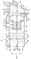
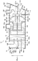
- the vehicle air conditioning unit 10 air-conditions the passenger compartment.
- the vehicle air-conditioning unit 10 is an internal / external air two-layer unit that can be set to an internal / external air mode that distinguishes between vehicle exterior air (hereinafter also referred to as “outside air”) and vehicle interior air (hereinafter also referred to as “inside air”). It is configured.
- the vehicle air conditioning unit 10 includes a casing 12 that forms an outer shell thereof.
- the casing 12 is formed with an airflow passage toward the passenger compartment.
- the casing 12 is provided with a partition portion 121 for partitioning the internal flow passage vertically.
- the inside of the casing 12 is divided by a partition 121 into a first flow passage 120a on the upper side and a second flow passage 120b on the lower side.
- the inside / outside air switching unit 14 is provided at the most upstream part of the air flow of the casing 12.
- the inside / outside air switching unit 14 is for introducing at least one of inside air and outside air into the casing 12.
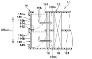
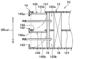
- the inside / outside air switching unit 14 introduces inside air into the outside air introduction port 141 for introducing outside air into the first flow passage 120a, the first inside air introduction port 142 for introducing inside air into the first flow passage 120a, and the second flow passage 120b.
- a second inside air introduction port 143 is formed.
- a communication passage 144 that guides the outside air introduced from the outside air introduction port 141 to the second flow passage 120b is formed inside the inside / outside air switching unit 14.
- a first opening / closing door 145 for selectively opening and closing the first inside air introduction port 142 and the outside air introduction port 141 is provided inside the inside / outside air switching unit 14.
- a second opening / closing door 146 that selectively opens and closes the second inside air introduction port 143 and the communication path 144 is provided inside the inside / outside air switching unit 14.
- the inside / outside air switching unit 14 is configured such that the first opening / closing door 145 opens the outside air introduction port 141 and closes the first inside air introduction port 142, and the second opening / closing door 146 opens the second inside air introduction port 143 and communicates with the communication path 144. Can be set to the closing position. Accordingly, the inside / outside air switching unit 14 is configured to be able to introduce outside air into the first flow passage 120a and introduce inside air into the second flow passage 120b.
- the inside / outside air switching unit 14 introduces outside air into the first flow passage 120a and introduces inside air into the second flow passage 120b
- the first opening / closing door 145 is in a position to open the outside air introduction port 141
- the second opening / closing door 146 is configured to open the second inside air introduction port 143.
- the first opening / closing door 145 is constituted by a cantilever door having a rotating shaft 145a driven by the electric actuator M1 and a plate-like door body portion 145b connected to the rotating shaft 145a.
- the second opening / closing door 146 is configured as a cantilever door having a rotating shaft 146a driven by the electric actuator M2 and a plate-like door main body 146b connected to the rotating shaft 146a.
- the operation of the electric actuators M1 and M2 of the open / close doors 145 and 146 is controlled by a control signal output from the control device 100 described later.
- Each of the open / close doors 145 and 146 is not limited to a cantilever door, and may be a rotary door or a film door.
- the blower 16 that generates an air flow toward the passenger compartment is disposed.
- the blower 16 is an electric blower that is driven by power feeding.
- the blower 16 includes a first fan 161, a second fan 162, and an electric motor 163.
- the first fan 161 is disposed in the first flow passage 120a.
- the first fan 161 is configured by a centrifugal fan that blows out air sucked along the axis of the rotating shaft toward the outside of the axis of the rotating shaft.
- the second fan 162 is disposed in the second flow passage 120b. Similar to the first fan 161, the second fan 162 is a centrifugal fan.
- the electric motor 163 rotates and drives the first fan 161 and the second fan 162.
- the electric motor 163 has a shaft 163 a connected to the first fan 161 and the second fan 162.
- the electric motor 163 of the present embodiment is disposed on the first flow path 120a side.
- an evaporator 18 is disposed on the upstream side of the air flow of the blower 16. That is, the evaporator 18 is arranged in a gap generated between the inside / outside air switching unit 14 and the first fan 161 and the second fan 162 in the casing 12.
- the evaporator 18 is a heat exchanger that constitutes a vapor compression refrigeration cycle including a compressor, a radiator, and a decompression device.
- the evaporator 18 uses the latent heat of vaporization of the refrigerant flowing inside the air to flow inside the casing 12. Cool down.
- the evaporator 18 constitutes a cooling heat exchanger that cools the air flowing inside the casing 12.
- the evaporator 18 is disposed so as to straddle the first flow path 120a and the second flow path 120b.
- the upper portion of the evaporator 18 is positioned in the first flow passage 120a, and the lower portion is positioned in the second flow passage 120b. For this reason, the air flowing through the first flow passage 120a is cooled at the upper portion of the evaporator 18.
- the air which flows through the 2nd flow path 120b is cooled in the site
- An air filter 19 is arranged between the inside / outside air switching unit 14 and the evaporator 18 inside the casing 12. That is, the air filter 19 is disposed in a gap generated between the inside / outside air switching unit 14 and the evaporator 18 inside the casing 12.
- the air filter 19 is a member for suppressing entry of foreign matter into the casing 12.
- the air filter 19 is disposed so as to straddle the first flow passage 120a and the second flow passage 120b.
- a heater core 20 is disposed inside the casing 12 on the downstream side of the air flow of the blower 16.
- the heater core 20 is a heat exchanger for heating that heats the air flowing in the casing 12 by using cooling water of an engine EG described later as a heat source.
- the heater core 20 is connected to a pipe TB constituting a circuit C through which the cooling water flows.
- the heater core 20 is disposed so as to straddle the first flow passage 120a and the second flow passage 120b.
- the upper part of the heater core 20 is positioned in the first flow path 120a, and the lower part is positioned in the second flow path 120b. For this reason, the air flowing through the first flow passage 120a is heated at the upper portion of the heater core 20.
- air flowing through the second flow passage 120b is heated at a lower portion of the heater core 20.
- a first bypass passage 120c is formed on the upper side of the heater core 20 in the first flow passage 120a to flow air around the heater core 20.
- the first flow passage 120 a is configured such that the air flowing through the first bypass passage 120 c and the air passing through the heater core 20 merge on the downstream side of the air flow of the heater core 20.
- the casing 12 is provided with a second bypass passage 120d that flows air around the heater core 20 on the lower side of the heater core 20 in the second flow passage 120b.
- the second flow passage 120b is configured such that the air flowing through the second bypass passage 120d and the air passing through the heater core 20 merge on the downstream side of the air flow of the heater core 20.
- the first air passage 120a of the casing 12 is provided with a first air mix door 22 that adjusts the flow rate ratio of air passing through the heater core 20 and air passing through the first bypass passage 120c.
- the first air mix door 22 is provided between the first fan 161 and the heater core 20.
- the first air mix door 22 is constituted by a cantilever door having a rotary shaft 221 driven by the electric actuator M3 and a plate-like door body portion 222 connected to the rotary shaft 221.
- the operation of the electric actuator M3 of the first air mix door 22 is controlled by a control signal output from the control device 100 described later.
- the 1st air mix door 22 is not restricted to a cantilever door, For example, you may be comprised by the film door.
- the second air passage 120b of the casing 12 is provided with a second air mix door 24 that adjusts the flow rate ratio of the air passing through the heater core 20 and the air passing through the second bypass passage 120d.
- the second air mix door 24 is provided between the second fan 162 and the heater core 20.
- the second air mix door 24 is constituted by a cantilever door having a rotary shaft 241 driven by the electric actuator M4 and a plate-like door main body portion 242 connected to the rotary shaft 241.
- the operation of the electric actuator M4 of the second air mix door 24 is controlled by a control signal output from the control device 100 described later.
- the 2nd air mix door 24 is not restricted to a cantilever door, For example, you may be comprised by the film door.
- a defroster opening 122, a face opening 123, and a foot opening 124 for leading the airflow flowing inside the casing 12 into the vehicle compartment are formed at the most downstream portion of the air flow of the casing 12.
- the defroster opening 122 is an opening hole for guiding the airflow flowing inside the casing 12 to the windshield of the vehicle.
- the defroster opening 122 is provided in a portion of the casing 12 that forms the first flow passage 120a. Although not shown, the defroster opening 122 communicates with a defroster outlet formed in the instrument panel IP through a duct.
- the face opening 123 is an opening hole for guiding the airflow flowing inside the casing 12 to the upper body of the occupant. Similar to the defroster opening 122, the face opening 123 is provided in a portion of the casing 12 where the first flow passage 120 a is formed. Although not shown, the face opening 123 communicates with a face outlet formed in the instrument panel IP via a duct.
- the foot opening 124 is an opening hole for guiding the airflow flowing inside the casing 12 to the lower body of the occupant.
- the foot opening 124 is provided in a part of the casing 12 where the second flow passage 120b is formed. Although not shown, the foot opening 124 communicates with the foot outlet opening inside the instrument panel IP through the duct.
- a defroster door 26, a face door 28, and a foot door 30 are provided in the casing 12.
- the defroster door 26 is a door that opens and closes the defroster opening 122, and is provided on the upstream side of the defroster opening 122.
- the face door 28 is a door that opens and closes the face opening 123, and is provided on the upstream side of the face opening 123.
- the foot door 30 is a door that opens and closes the foot opening 124, and is provided on the upstream side of the foot opening 124.
- the partition portion 121 is formed with a downstream communication passage 121a that communicates the first flow passage 120a and the second flow passage 120b on the downstream side of the air flow of the heater core 20.
- the downstream communication path 121a is opened and closed by the foot door 30. That is, the foot door 30 of the present embodiment is configured to selectively open and close the foot opening 124 and the downstream communication path 121a.
- the defroster door 26, the face door 28, and the foot door 30 are configured such that their respective rotation shafts are connected via a link mechanism (not shown) and driven by a common electric actuator M5.
- the operation of the electric actuator M5 shared by the doors 26, 28, and 30 is controlled by a control signal output from the control device 100 described later.
- the vehicular air conditioning unit 10 configured as described above has an evaporator 18 disposed on the upstream side of the air flow of the blower 16 and a heater core 20 disposed on the downstream side of the air flow of the blower 16 inside the casing 12.
- positioned may be called cooler site
- positioned may be called heater site
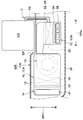
- the vehicle air conditioning unit 10 is disposed inside the foremost instrument panel IP in the vehicle interior.
- the instrument panel IP is positioned on the vehicle rear side of the firewall FW.
- the firewall FW is a metal wall that is disposed on the front side of the vehicle with respect to the vehicle interior and divides the vehicle interior and a device storage chamber MR in which various devices for driving the vehicle including the engine EG are stored. .
- the firewall FW extends along the vehicle width direction DRw.
- an engine EG is disposed at a substantially central portion in the vehicle width direction DRw.
- a substantially central portion of the firewall FW in the width direction DRw of the vehicle is configured to swell toward the vehicle rear side. That is, the firewall FW has a bulging portion EP in which a substantially central portion in the vehicle width direction DRw bulges toward the vehicle rear side.
- the distance between the firewall FW and the instrument panel IP is reduced on the vehicle rear side of the engine EG. That is, the space inside the instrument panel IP is reduced on the vehicle rear side of the engine EG. For this reason, the installation space of the vehicle air conditioning unit 10 on the vehicle rear side of the engine EG is greatly limited.
- the heater part 10B in the vehicle air conditioning unit 10 is arranged on the vehicle rear side of the engine EG, and the cooler part 10A is arranged in an offset state in the vehicle width direction DRw with respect to the heater part 10B. ing. That is, the cooler part 10A is disposed at a position shifted in the vehicle width direction DRw with respect to the heater part 10B. Specifically, the cooler part 10A is arranged at a position avoiding the bulging part EP in the firewall FW.
- the cooler part 10A on the passenger seat side (left side in this example) in the vehicle width direction DRw.
- the cooler portion 10A is arranged in the vehicle width direction DRw in order of the inside / outside air switching unit 14, the air filter 19, the evaporator 18, and the blower 16 so as to be separated from the center portion in the vehicle width direction DRw.
- the cooler portion 10A has a posture in which the air filter 19 and the evaporator 18 stand up and down so that the size of the vehicle in the width direction DRw of the vehicle does not become too large, and the ventilation surface thereof extends along the front-rear direction DRfr. Is arranged.
- cooler part 10 ⁇ / b> A is configured so that the inside air inlets 142 and 143 face the ventilation surfaces of the air filter 19 and the evaporator 18 so that the inside air is easily introduced into the air filter 19 and the evaporator 18. Is provided.
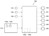
- the control device 100 which is an electronic control unit of the vehicle air conditioning unit 10 will be described with reference to FIG.
- the control device 100 includes a microcomputer including a processor 100a and a memory 100b and its peripheral circuits.
- the memory 100b is composed of a non-transitional tangible storage medium.
- an outside air temperature sensor 101 that detects the outside air temperature Tam
- an inside air temperature sensor 102 that detects the inside air temperature Tr
- a solar radiation sensor 103 that detects the amount of solar radiation Ts in the vehicle interior. Etc. are connected.
- An operation panel 110 provided with an air conditioning switch 110a for setting on / off of the air conditioning operation and a temperature setting switch 110b for setting a set temperature Tset in the passenger compartment is connected to the input side of the control device 100.
- various devices such as an electric motor 163 of the blower 16 and electric actuators M1 to M5 for driving the various doors 145, 146, 22, 24, 26, 28, and 30 are connected to the output side of the control device 100. .
- the control device 100 performs arithmetic processing on the information read from the device connected to the input side according to the control program stored in the memory 100b. And the control apparatus 100 outputs a control signal with respect to the various control apparatuses connected to the output side based on the processing result etc. of arithmetic processing.
- the control device 100 calculates a target blowing temperature TAO that is a target temperature of the blowing air blown into the vehicle interior based on information read from a device connected to the input side. For example, the control device 100 calculates the target blowing temperature TAO based on the following formula F1.
- TAO Kset ⁇ Tset ⁇ Kr ⁇ Tr ⁇ Kam ⁇ Tam ⁇ Ks ⁇ Ts + C (F1)
- Tset is a set temperature set by the temperature setting switch 110b.
- Tr is the inside air temperature detected by the inside air temperature sensor 102.
- Tam is the outside air temperature detected by the outside air temperature sensor 101.
- Ts is the amount of solar radiation detected by the solar radiation sensor 103.
- Kset, Kr, and Kam are control gains.
- C is a constant for correction.
- the control device 100 controls the electric motor 163 of the blower 16, the electric actuators M3 and M4 of the air mix doors 22 and 24, and the electric actuator M5 of the doors 26, 28 and 30 based on the target blowing temperature TAO.
- control device 100 controls the open / close doors 145 and 146 of the inside / outside air switching unit 14 based on information such as the inside temperature Tr and the outside temperature Tam. Specifically, the control device 100 controls the open / close doors 145 and 146 of the inside / outside air switching unit 14 to change the air suction mode into the casing 12 to any one of the outside air mode, the inside air mode, and the inside / outside air mode. change.
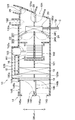
- the control device 100 basically controls the open / close doors 145 and 146 of the inside / outside air switching unit 14 so as to be in the outside air mode. Specifically, in the outside air mode, the control device 100 opens and closes the first opening / closing door 145 so that the first opening / closing door 145 opens the outside air introduction port 141 and closes the first inside air introduction port 142 as shown in FIG. Control the door 145. In addition, the control device 100 controls the second opening / closing door 146 so that the second opening / closing door 146 is positioned to open the communication path 144 and close the second inside air introduction port 143 in the outside air mode.
- the control device 100 controls the open / close doors 145 and 146 of the inside / outside air switching unit 14 so as to be in the inside air mode when the temperature difference between the inside temperature Tr and the outside temperature Tam is large and the ventilation loss due to the introduction of outside air becomes large. To do. Specifically, in the inside air mode, the control device 100 opens and closes the first opening / closing door 145 so that the first opening / closing door 145 opens the first inside air introduction port 142 and closes the outside air introduction port 141 as shown in FIG. Control the door 145. Further, the control device 100 controls the second opening / closing door 146 so that the second opening / closing door 146 is positioned to open the second inside air introduction port 143 and close the communication path 144 in the inside air mode.
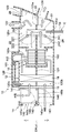
- the control device 100 controls the open / close doors 145 and 146 of the inside / outside air switching unit 14 so as to enter the inside / outside air mode when the ventilation loss due to the introduction of outside air becomes large and fogging of the window glass of the vehicle is predicted. To do.
- the control device 100 sets the first opening / closing door 145 so that the first open / close door 145 opens the outside air introduction port 141 and closes the first inside air introduction port 142 as shown in FIG.
- the open / close door 145 is controlled.
- the control device 100 controls the second opening / closing door 146 so that the second opening / closing door 146 is positioned to open the second inside air introduction port 143 and close the communication path 144 in the inside / outside air mode.
- the inside / outside air mode is a suction mode that prevents fogging of the window glass of the vehicle while suppressing loss of ventilation due to introduction of outside air.
- the fogging of the window glass is likely to occur in winter when the outside temperature is low and the passenger compartment needs to be heated.
- the control device 100 controls the defroster door 26 to a position where the defroster opening 122 is opened and controls the face door 28 to a position where the face opening 123 is closed.
- the control device 100 controls the foot door 30 to a position where the foot opening 124 is opened and the downstream communication path 121a is closed.
- FIG. 6 illustrates a state in which the air mix doors 22 and 24 are controlled to positions that close the bypass passages 120c and 120d.
- the air mix doors 22 and 24 may be controlled to positions where the bypass passages 120c and 120d are opened.
- the outside air introduced into the first flow passage 120a is blown out toward the inner surface of the window glass in the vehicle interior via the air filter 19, the evaporator 18, the first fan 161, the heater core 20, the defroster opening 122, and the like. Thereby, the relative humidity in the vicinity of the inner surface of the window glass is lowered, so that the window glass is hardly fogged.
- the inside air introduced into the second flow passage 120b is blown out toward the lower body of the occupant through the air filter 19, the evaporator 18, the second fan 162, the heater core 20, the foot opening 124, and the like.
- the temperature in the vicinity of the lower body of the occupant is adjusted to an appropriate temperature.
- the evaporator 18 is disposed between the first fan 161 and the second fan 162 and the inside / outside air switching unit 14 in the casing 12. According to this, it is not necessary to provide an installation space for the evaporator 18 on the air flow downstream side of the blower 16. For this reason, compared with the case where the evaporator 18 is arrange
- positioned in the air flow downstream of the air blower 16 size reduction of the physique of the air flow downstream of the air blower 16 can be achieved. Further, when the physique on the downstream side of the air flow of the blower 16 is simply downsized, it is conceivable to arrange the blower 16 on the downstream side of the heater core 20.
- the blower 16 when the blower 16 is disposed on the downstream side of the heater core 20, the distance between the blower 16 and each of the openings 122 to 124 is reduced. This is not preferable because the airflow flowing through the openings 122 to 124 is greatly disturbed and noise of the blower 16 is easily transmitted to the vehicle interior via the openings 122 to 124.
- the heater core 20 is disposed on the downstream side of the blower 16. According to this, the airflow blown out from the blower 16 is rectified when passing through the heater core 20, so that the turbulence of the airflow flowing through the openings 122 to 124 can be suppressed.
- the heater core 20 functions as a soundproof member that suppresses the noise of the blower 16, it is possible to suppress the noise of the blower 16 from being transmitted to the vehicle interior via the openings 122 to 124. Therefore, the vehicle air conditioning unit 10 can suppress the noise of the blower 16 and the disturbance of the airflow flowing through the openings 122 to 124 while reducing the size of the blower 16 on the downstream side.
- the heater part 10B in the casing 12 is disposed on the vehicle rear side of the engine EG, and the cooler part 10A and the inside / outside air switching unit 14 are in the vehicle width direction DRw with respect to the heater part 10B. It is arranged in an offset state. According to this, even if the installation space of the vehicle air conditioning unit 10 is greatly restricted on the vehicle rear side of the engine EG, the vehicle air conditioning unit 10 can be mounted on the vehicle.
- the bypass passages 120c and 120d are formed in the heater part 10B, and the air mix doors 22 and 24 are provided.
- the cooler part 10A including the evaporator 18 is disposed on the upstream side of the air flow of the blower 16, the physique on the downstream side of the air flow of the blower 16 can be downsized. It becomes possible to avoid the deterioration of the mountability to the vehicle.
- the heater core 20 and the engine EG can be brought close to each other. According to this, since the pipe TB connecting the heater core 20 and the engine EG can be shortened, the circuit C through which the cooling water for the engine EG flows can be simplified. Such simplification contributes to the improvement of the mountability of the vehicle air conditioning unit 10.
- the second open / close door 146 of the inside / outside air switching unit 14 closes the communication passage 144 between the first flow passage 120a and the second flow passage 120b in the inside / outside air mode. It is configured.
- the second opening / closing door 146 functions as a partition member that partitions the first flow passage 120 a and the second flow passage 120 b in the inside / outside air switching unit 14 in the inside / outside air mode. According to this, compared with the case where a dedicated door for opening and closing the communication path 144 is provided, the number of parts of the inside / outside air switching unit 14 is reduced, and the inside / outside air switching unit 14 can be downsized. Since downsizing of the inside / outside air switching unit 14 leads to suppression of an increase in the size of the air blower 16 on the upstream side of the air flow, it greatly contributes to downsizing of the vehicle air conditioning unit 10 as a whole.
- an air filter 19 for suppressing the intrusion of foreign matter is disposed between the inside / outside air switching unit 14 and the evaporator 18. According to this, since the foreign matter from the outside can be removed by the air filter 19 before flowing into the evaporator 18, an increase in the ventilation resistance of the evaporator 18 due to the foreign matter can be avoided. Further, in the configuration in which the air filter 19 is disposed on the upstream side of the blower 16, the physique on the downstream side of the blower 16 in the vehicle air conditioning unit 10 is compared with the configuration in which the air filter 19 is disposed on the downstream side of the blower 16. Can be suppressed.
- the vehicle air conditioning unit 10 of the present embodiment has a structure capable of cooling the electric motor 163 of the blower 16.
- portions different from those in the first embodiment will be mainly described, and description of similar portions may be omitted.
- the vehicle air conditioning unit 10 is provided with a cooling passage 128 for the casing 12.
- the cooling passage portion 128 is for guiding air for cooling the electric motor 163 of the blower 16 to the periphery of the electric motor 163.
- the surface temperature of the electric motor 163 is excessively lowered, and the electric motor Condensation may occur on the surface of 163. Such condensation is not preferable because it causes a decrease in insulation and a failure of the electric motor 163.
- the cooling passage portion 128 is upstream of the evaporator 18 in the casing 12 so that the air upstream of the evaporator 18 in the casing 12 is guided to the electric motor 163. It is connected to the side part. Specifically, the cooling passage portion 128 is connected to a portion of the casing 12 upstream of the evaporator 18 and forming a first flow passage 120a through which outside air flows in the inside / outside air mode.
- the vehicle air conditioning unit 10 of the present embodiment is configured such that a part of the air on the upstream side of the evaporator 18 is supplied to the electric motor 163 through the cooling passage portion 128. According to this, since it is possible to suppress an excessive decrease in the surface temperature of the electric motor 163, it is possible to avoid problems associated with condensation on the surface of the electric motor 163.
- the cooling passage portion 128 is connected to the first flow passage 120a.
- the first flow passage 120a circulates outside air whose relative humidity tends to be lower than that of the inside air in the inside / outside air mode. For this reason, it is possible to sufficiently suppress the occurrence of condensation on the surface of the electric motor 163 by connecting the cooling passage portion 128 to the first flow passage 120a.
- the second opening / closing door 146 of the inside / outside air switching unit 14 functions as a member that partitions the first flow path 120a and the second flow path 120b in the inside / outside air mode.
- the inside / outside air switching unit 14 may be configured to open and close the communication path 144 with a dedicated door, for example.
- first fan 161 and the second fan 162 of the blower 16 are centrifugal fans
- present invention is not limited to this.
- the first fan 161 and the second fan 162 may be configured by a fan (for example, an axial fan) other than the centrifugal fan.
- the blower 16 may be configured such that each of the first fan 161 and the second fan 162 is rotationally driven by an independent electric motor.
- positioned at the 1st flow path 120a side it is not limited to this.
- the electric motor 163 may be configured to be disposed on the second flow path 120b side or disposed between the first fan 161 and the second fan 162.
- the evaporator 18 is exemplified as the cooling heat exchanger, but the present invention is not limited to this.
- the cooling heat exchanger is not limited as long as it can cool the air, and may be composed of something other than the evaporator 18 (for example, a Peltier module).
- the heater core 20 is exemplified as the heat exchanger for heating, but the present invention is not limited to this.
- the heating heat exchanger is not limited as long as it can heat air, and may be composed of other than the heater core 20 (for example, an electric heater).
- the vehicle air conditioning unit 10 is exemplified by a configuration that adjusts the temperature of the air blown into the vehicle interior by the air mix doors 22 and 24, but is not limited thereto.
- the vehicle air conditioning unit 10 may be configured, for example, to adjust the temperature of air blown out into the passenger compartment by adjusting the heat dissipation capability of the heating heat exchanger. In such a configuration, since it is not necessary to provide the bypass passages 120c and 120d inside the casing 12, the air flow downstream side of the blower 16 can be downsized.
- the air filter 19 is arranged on the upstream side of the air flow of the evaporator 18 in the casing 12 has been described, but the present invention is not limited to this.
- the air filter 19 may be disposed inside the inside / outside air switching unit 14.
- the heater part 10B is arranged on the vehicle rear side of the engine EG, and the cooler part 10A and the inside / outside air switching unit 14 are arranged in an offset state in the vehicle width direction DRw with respect to the heater part 10B.
- the present invention is not limited to this.
- each of the cooler part 10 ⁇ / b> A, the heater part 10 ⁇ / b> B, and the inside / outside air switching unit 14 may be disposed at a substantially central part in the vehicle width direction DRw.
- a vehicle air-conditioning unit is a fan, the casing in which the 1st flow path and the 2nd flow path were formed, the inside / outside air switching part, cooling Heat exchanger and heating heat exchanger.
- the blower is configured to include a first fan disposed in the first flow path and a second fan disposed in the second flow path.
- the inside / outside air switching unit is configured to be able to introduce vehicle interior air into the first flow passage and introduce vehicle interior air into the second flow passage.
- the heat exchanger for cooling is arrange
- the blower of the vehicle air conditioning unit is configured by an electric blower that drives the first fan and the second fan by at least one electric motor.
- the casing is provided with a cooling passage portion that guides air for cooling the electric motor to the periphery of the electric motor.
- path part is comprised so that the air more upstream than the heat exchanger for cooling may be guide
- the vehicle air conditioning unit includes a cooler part in which a cooling heat exchanger and a blower in the casing are arranged, and a heater part in which the heating heat exchanger in the casing is arranged.
- the vehicle air-conditioning unit is disposed in a state where the heater part is disposed on the vehicle rear side of the engine that drives the vehicle, and the cooler part is offset in the vehicle width direction with respect to the heater part.
- the installation space for the vehicle air conditioning unit on the vehicle rear side of the engine may be greatly limited. For this reason, it is desirable that the vehicle air-conditioning unit be disposed in a state where the heater portion is disposed on the vehicle rear side of the engine and the cooler portion is offset from the heater portion in the vehicle width direction.
- the heat exchanger for heating of the vehicle air conditioning unit is configured by a heater core that heats air flowing inside the casing using engine cooling water as a heat source. According to this, since the heater core and the engine can be brought close to each other, the circuit through which the engine coolant flows can be simplified. Such simplification contributes to an improvement in mountability of the vehicle air conditioning unit.
- the inside / outside air switching unit of the vehicle air conditioning unit is arranged in an offset state in the vehicle width direction with respect to the heater part. According to this, even when the installation space of the vehicle air conditioning unit on the vehicle rear side of the engine is greatly restricted, it is possible to ensure the mountability of the vehicle air conditioning unit on the vehicle.
- the inside / outside air switching unit of the vehicle air conditioning unit includes an outside air introduction port that introduces outside air into the first flow passage, and a first inside air introduction that introduces inside air into the first flow passage. And a second inside air introduction port for introducing vehicle interior air into the second flow passage.
- the inside / outside air switching unit includes a communication path that guides the outside air introduced from the outside air introduction port to the second flow passage, a first opening / closing door that selectively opens and closes the first inside air introduction port and the outside air introduction port, And a second open / close door that selectively opens and closes the second inside air introduction port and the communication passage.
- the inside / outside air switching unit opens the outside air inlet and opens the outside air inlet when the outside air is introduced into the first flow passage and the inside air is introduced into the second flow passage. It is comprised so that it may become a position which closes an inlet.
- the inside / outside air switching unit introduces outside air into the first flow passage and introduces inside air into the second flow passage, and the second open / close door opens the second inside air inlet, It is comprised so that it may become a position which closes a communicating path.
- the second open / close door is connected to the first flow passage and the first flow passage in the inside / outside air switching unit. It functions as a partition member that partitions the two flow paths. According to this, compared with the case where the door for exclusive use which opens and closes a communicating path is provided, the number of parts of an inside / outside switching part decreases, and it becomes possible to achieve size reduction of an inside / outside air switching part.
- the downsizing of the inside / outside air switching unit leads to suppression of an increase in the physique on the upstream side of the air flow of the blower, and greatly contributes to improvement of the mounting of the vehicle air conditioning unit on the vehicle.
- the vehicle air conditioning unit includes an air filter for suppressing intrusion of foreign matter.
- the air filter is disposed between the inside / outside air switching unit and the cooling heat exchanger. According to this, since the foreign matter from the outside can be removed by the air filter before flowing into the cooling heat exchanger, an increase in the ventilation resistance of the cooling heat exchanger due to the foreign matter can be avoided.
- the casing of the vehicle air conditioning unit is formed with the first bypass passage for flowing the air flowing through the first flow passage around the heat exchanger for heating, and the second flow passage.
- a second bypass passage is formed to flow the air flowing through the heat bypassing the heat exchanger.
- the casing includes a first air mix door for adjusting a flow rate ratio of air passing through the heat exchanger for heating and air passing through the first bypass passage, air passing through the heat exchanger for heating, and the first bypass passage.
- a second air mix door that adjusts the flow rate of the passing air is provided.
- each bypass passage is provided on the side of the heating heat exchanger and the flow rate ratio of the air flowing into the heating heat exchanger by each air mix door and the air flowing through each bypass passage is adjustable.
- the size of the area near the heat exchanger for heating tends to increase.
- the cooling heat exchanger is arranged on the upstream side of the air flow of the blower, the physique on the downstream side of the air flow of the blower can be downsized. It becomes possible to avoid the deterioration of the mounting property.
Landscapes
- Engineering & Computer Science (AREA)
- Mechanical Engineering (AREA)
- Physics & Mathematics (AREA)
- Thermal Sciences (AREA)
- Air-Conditioning For Vehicles (AREA)
Applications Claiming Priority (2)
| Application Number | Priority Date | Filing Date | Title |
|---|---|---|---|
| JP2018-050638 | 2018-03-19 | ||
| JP2018050638A JP2019162894A (ja) | 2018-03-19 | 2018-03-19 | 車両用空調ユニット |
Publications (1)
| Publication Number | Publication Date |
|---|---|
| WO2019181262A1 true WO2019181262A1 (ja) | 2019-09-26 |
Family
ID=67986937
Family Applications (1)
| Application Number | Title | Priority Date | Filing Date |
|---|---|---|---|
| PCT/JP2019/004417 Ceased WO2019181262A1 (ja) | 2018-03-19 | 2019-02-07 | 車両用空調ユニット |
Country Status (2)
| Country | Link |
|---|---|
| JP (1) | JP2019162894A (cg-RX-API-DMAC7.html) |
| WO (1) | WO2019181262A1 (cg-RX-API-DMAC7.html) |
Families Citing this family (3)
| Publication number | Priority date | Publication date | Assignee | Title |
|---|---|---|---|---|
| KR102720065B1 (ko) * | 2020-06-03 | 2024-10-22 | 한온시스템 주식회사 | 차량용 공조장치 |
| KR102720069B1 (ko) * | 2020-06-03 | 2024-10-22 | 한온시스템 주식회사 | 차량용 공조장치 |
| KR102806025B1 (ko) * | 2020-06-03 | 2025-05-14 | 한온시스템 주식회사 | 차량용 공조장치 |
Citations (4)
| Publication number | Priority date | Publication date | Assignee | Title |
|---|---|---|---|---|
| JPH11334340A (ja) * | 1998-03-25 | 1999-12-07 | Denso Corp | 車両用空調装置 |
| JP2006264671A (ja) * | 2005-02-22 | 2006-10-05 | Denso Corp | 車両用空調装置 |
| JP2014065334A (ja) * | 2012-09-24 | 2014-04-17 | Denso Corp | 車両用空調装置 |
| WO2017221460A1 (ja) * | 2016-06-21 | 2017-12-28 | 株式会社デンソー | 空調装置 |
Family Cites Families (7)
| Publication number | Priority date | Publication date | Assignee | Title |
|---|---|---|---|---|
| JP3758269B2 (ja) * | 1997-01-31 | 2006-03-22 | 株式会社デンソー | 車両用空気調和装置 |
| JP3726552B2 (ja) * | 1999-05-06 | 2005-12-14 | 日産自動車株式会社 | 車両用空調装置 |
| JP2002036850A (ja) * | 2000-07-24 | 2002-02-06 | Denso Corp | 車両用空調装置の送風ユニット |
| JP4394812B2 (ja) * | 2000-08-23 | 2010-01-06 | 株式会社日本クライメイトシステムズ | 車両用空調装置 |
| JP2003291623A (ja) * | 2002-03-29 | 2003-10-15 | Calsonic Kansei Corp | 車両用空調装置 |
| JP5465520B2 (ja) * | 2009-01-09 | 2014-04-09 | カルソニックカンセイ株式会社 | 車両用空調装置 |
| CN102724617B (zh) * | 2011-03-29 | 2015-06-03 | 清华大学 | 热致发声装置及电子装置 |
-
2018
- 2018-03-19 JP JP2018050638A patent/JP2019162894A/ja active Pending
-
2019
- 2019-02-07 WO PCT/JP2019/004417 patent/WO2019181262A1/ja not_active Ceased
Patent Citations (4)
| Publication number | Priority date | Publication date | Assignee | Title |
|---|---|---|---|---|
| JPH11334340A (ja) * | 1998-03-25 | 1999-12-07 | Denso Corp | 車両用空調装置 |
| JP2006264671A (ja) * | 2005-02-22 | 2006-10-05 | Denso Corp | 車両用空調装置 |
| JP2014065334A (ja) * | 2012-09-24 | 2014-04-17 | Denso Corp | 車両用空調装置 |
| WO2017221460A1 (ja) * | 2016-06-21 | 2017-12-28 | 株式会社デンソー | 空調装置 |
Also Published As
| Publication number | Publication date |
|---|---|
| JP2019162894A (ja) | 2019-09-26 |
Similar Documents
| Publication | Publication Date | Title |
|---|---|---|
| JP3960020B2 (ja) | 車両用空調装置 | |
| JP6414344B2 (ja) | 気流制御システム | |
| JP6729606B2 (ja) | 車両用空調装置 | |
| WO2012114573A1 (ja) | 車両用空調装置 | |
| US10926604B2 (en) | Air conditioner | |
| WO2012144153A1 (ja) | 車両用空調装置 | |
| JPH10230734A (ja) | 車両用空調装置 | |
| JPH10250342A (ja) | 車両用空調装置 | |
| JP2019162894A (ja) | 車両用空調ユニット | |
| JP3978826B2 (ja) | 車両用空調装置 | |
| JP2005067402A (ja) | 車両用空調装置 | |
| CN109311365B (zh) | 连杆机构 | |
| CN113453922B (zh) | 车辆用空调单元 | |
| JP5012758B2 (ja) | 車両用空調装置 | |
| JP4042537B2 (ja) | 車両用空調装置 | |
| JP6488694B2 (ja) | 冷凍サイクル装置 | |
| KR20200058887A (ko) | 차량용 공조장치 | |
| JP4075627B2 (ja) | 車両用空調装置 | |
| KR102610904B1 (ko) | 전기자동차용 공조장치 | |
| JP4687435B2 (ja) | 車両用空調装置 | |
| JP4978572B2 (ja) | リンク機構 | |
| JP4140458B2 (ja) | 車両用空調装置 | |
| JP2005225249A (ja) | 車両用空調装置 | |
| WO2023182220A1 (ja) | 車両用空調装置 | |
| CN111565947B (zh) | 车辆用空调单元 |
Legal Events
| Date | Code | Title | Description |
|---|---|---|---|
| 121 | Ep: the epo has been informed by wipo that ep was designated in this application |
Ref document number: 19772569 Country of ref document: EP Kind code of ref document: A1 |
|
| NENP | Non-entry into the national phase |
Ref country code: DE |
|
| 122 | Ep: pct application non-entry in european phase |
Ref document number: 19772569 Country of ref document: EP Kind code of ref document: A1 |