WO2019163671A1 - 線状物の先端移動方法、制御装置、および、三次元カメラ - Google Patents
線状物の先端移動方法、制御装置、および、三次元カメラ Download PDFInfo
- Publication number
- WO2019163671A1 WO2019163671A1 PCT/JP2019/005611 JP2019005611W WO2019163671A1 WO 2019163671 A1 WO2019163671 A1 WO 2019163671A1 JP 2019005611 W JP2019005611 W JP 2019005611W WO 2019163671 A1 WO2019163671 A1 WO 2019163671A1
- Authority
- WO
- WIPO (PCT)
- Prior art keywords
- tip
- linear object
- robot hand
- moving
- robot
- Prior art date
Links
Images


Classifications
-
- B—PERFORMING OPERATIONS; TRANSPORTING
- B25—HAND TOOLS; PORTABLE POWER-DRIVEN TOOLS; MANIPULATORS
- B25J—MANIPULATORS; CHAMBERS PROVIDED WITH MANIPULATION DEVICES
- B25J9/00—Programme-controlled manipulators
- B25J9/16—Programme controls
- B25J9/1679—Programme controls characterised by the tasks executed
- B25J9/1687—Assembly, peg and hole, palletising, straight line, weaving pattern movement
-
- B—PERFORMING OPERATIONS; TRANSPORTING
- B23—MACHINE TOOLS; METAL-WORKING NOT OTHERWISE PROVIDED FOR
- B23P—METAL-WORKING NOT OTHERWISE PROVIDED FOR; COMBINED OPERATIONS; UNIVERSAL MACHINE TOOLS
- B23P19/00—Machines for simply fitting together or separating metal parts or objects, or metal and non-metal parts, whether or not involving some deformation; Tools or devices therefor so far as not provided for in other classes
- B23P19/04—Machines for simply fitting together or separating metal parts or objects, or metal and non-metal parts, whether or not involving some deformation; Tools or devices therefor so far as not provided for in other classes for assembling or disassembling parts
-
- B—PERFORMING OPERATIONS; TRANSPORTING
- B25—HAND TOOLS; PORTABLE POWER-DRIVEN TOOLS; MANIPULATORS
- B25J—MANIPULATORS; CHAMBERS PROVIDED WITH MANIPULATION DEVICES
- B25J13/00—Controls for manipulators
- B25J13/08—Controls for manipulators by means of sensing devices, e.g. viewing or touching devices
-
- B—PERFORMING OPERATIONS; TRANSPORTING
- B25—HAND TOOLS; PORTABLE POWER-DRIVEN TOOLS; MANIPULATORS
- B25J—MANIPULATORS; CHAMBERS PROVIDED WITH MANIPULATION DEVICES
- B25J19/00—Accessories fitted to manipulators, e.g. for monitoring, for viewing; Safety devices combined with or specially adapted for use in connection with manipulators
- B25J19/02—Sensing devices
- B25J19/021—Optical sensing devices
- B25J19/023—Optical sensing devices including video camera means
-
- B—PERFORMING OPERATIONS; TRANSPORTING
- B25—HAND TOOLS; PORTABLE POWER-DRIVEN TOOLS; MANIPULATORS
- B25J—MANIPULATORS; CHAMBERS PROVIDED WITH MANIPULATION DEVICES
- B25J9/00—Programme-controlled manipulators
- B25J9/16—Programme controls
- B25J9/1612—Programme controls characterised by the hand, wrist, grip control
-
- B—PERFORMING OPERATIONS; TRANSPORTING
- B25—HAND TOOLS; PORTABLE POWER-DRIVEN TOOLS; MANIPULATORS
- B25J—MANIPULATORS; CHAMBERS PROVIDED WITH MANIPULATION DEVICES
- B25J9/00—Programme-controlled manipulators
- B25J9/16—Programme controls
- B25J9/1656—Programme controls characterised by programming, planning systems for manipulators
- B25J9/1664—Programme controls characterised by programming, planning systems for manipulators characterised by motion, path, trajectory planning
- B25J9/1666—Avoiding collision or forbidden zones
-
- B—PERFORMING OPERATIONS; TRANSPORTING
- B25—HAND TOOLS; PORTABLE POWER-DRIVEN TOOLS; MANIPULATORS
- B25J—MANIPULATORS; CHAMBERS PROVIDED WITH MANIPULATION DEVICES
- B25J9/00—Programme-controlled manipulators
- B25J9/16—Programme controls
- B25J9/1694—Programme controls characterised by use of sensors other than normal servo-feedback from position, speed or acceleration sensors, perception control, multi-sensor controlled systems, sensor fusion
-
- B—PERFORMING OPERATIONS; TRANSPORTING
- B25—HAND TOOLS; PORTABLE POWER-DRIVEN TOOLS; MANIPULATORS
- B25J—MANIPULATORS; CHAMBERS PROVIDED WITH MANIPULATION DEVICES
- B25J15/00—Gripping heads and other end effectors
-
- B—PERFORMING OPERATIONS; TRANSPORTING
- B25—HAND TOOLS; PORTABLE POWER-DRIVEN TOOLS; MANIPULATORS
- B25J—MANIPULATORS; CHAMBERS PROVIDED WITH MANIPULATION DEVICES
- B25J9/00—Programme-controlled manipulators
- B25J9/16—Programme controls
- B25J9/1694—Programme controls characterised by use of sensors other than normal servo-feedback from position, speed or acceleration sensors, perception control, multi-sensor controlled systems, sensor fusion
- B25J9/1697—Vision controlled systems
-
- G—PHYSICS
- G05—CONTROLLING; REGULATING
- G05B—CONTROL OR REGULATING SYSTEMS IN GENERAL; FUNCTIONAL ELEMENTS OF SUCH SYSTEMS; MONITORING OR TESTING ARRANGEMENTS FOR SUCH SYSTEMS OR ELEMENTS
- G05B2219/00—Program-control systems
- G05B2219/30—Nc systems
- G05B2219/37—Measurements
- G05B2219/37555—Camera detects orientation, position workpiece, points of workpiece
-
- G—PHYSICS
- G05—CONTROLLING; REGULATING
- G05B—CONTROL OR REGULATING SYSTEMS IN GENERAL; FUNCTIONAL ELEMENTS OF SUCH SYSTEMS; MONITORING OR TESTING ARRANGEMENTS FOR SUCH SYSTEMS OR ELEMENTS
- G05B2219/00—Program-control systems
- G05B2219/30—Nc systems
- G05B2219/40—Robotics, robotics mapping to robotics vision
- G05B2219/40028—Insert flexible rod, beam into hole
-
- G—PHYSICS
- G05—CONTROLLING; REGULATING
- G05B—CONTROL OR REGULATING SYSTEMS IN GENERAL; FUNCTIONAL ELEMENTS OF SUCH SYSTEMS; MONITORING OR TESTING ARRANGEMENTS FOR SUCH SYSTEMS OR ELEMENTS
- G05B2219/00—Program-control systems
- G05B2219/30—Nc systems
- G05B2219/40—Robotics, robotics mapping to robotics vision
- G05B2219/40082—Docking, align object on end effector with target
-
- G—PHYSICS
- G05—CONTROLLING; REGULATING
- G05B—CONTROL OR REGULATING SYSTEMS IN GENERAL; FUNCTIONAL ELEMENTS OF SUCH SYSTEMS; MONITORING OR TESTING ARRANGEMENTS FOR SUCH SYSTEMS OR ELEMENTS
- G05B2219/00—Program-control systems
- G05B2219/30—Nc systems
- G05B2219/40—Robotics, robotics mapping to robotics vision
- G05B2219/40609—Camera to monitor end effector as well as object to be handled
-
- G—PHYSICS
- G05—CONTROLLING; REGULATING
- G05B—CONTROL OR REGULATING SYSTEMS IN GENERAL; FUNCTIONAL ELEMENTS OF SUCH SYSTEMS; MONITORING OR TESTING ARRANGEMENTS FOR SUCH SYSTEMS OR ELEMENTS
- G05B2219/00—Program-control systems
- G05B2219/30—Nc systems
- G05B2219/45—Nc applications
- G05B2219/45097—Cable harnessing robot
-
- H—ELECTRICITY
- H01—ELECTRIC ELEMENTS
- H01R—ELECTRICALLY-CONDUCTIVE CONNECTIONS; STRUCTURAL ASSOCIATIONS OF A PLURALITY OF MUTUALLY-INSULATED ELECTRICAL CONNECTING ELEMENTS; COUPLING DEVICES; CURRENT COLLECTORS
- H01R43/00—Apparatus or processes specially adapted for manufacturing, assembling, maintaining, or repairing of line connectors or current collectors or for joining electric conductors
- H01R43/28—Apparatus or processes specially adapted for manufacturing, assembling, maintaining, or repairing of line connectors or current collectors or for joining electric conductors for wire processing before connecting to contact members, not provided for in groups H01R43/02 - H01R43/26
Definitions
- the present invention relates to a method for moving the tip of a linear object, a control device, and a three-dimensional camera when the linear object is gripped using a robot hand.
- Patent Document 1 Japanese Patent Application Laid-Open No. 2014-176917
- Patent Document 2 a robot apparatus for assembling a linear object, in which the fixed end of the linear object with one end fixed is fixed.
- An apparatus is described in which after gripping the vicinity, the gripper is slid along a predetermined locus and moved to the other end. Accordingly, it is possible to quickly grasp the other end that is difficult to accurately estimate with a hook or the like attached to an electric wire that is an example of a linear object.
- Patent Document 2 discloses an invention relating to a method for manufacturing a wire harness and an image processing method, and in the course of manufacturing the wire harness, the three-dimensional shape of the wire assembly is measured. A processing position specifying process is performed in which the processing position is specified.
- the robot hand holds a wire or the like as a linear object and performs control to move the tip of the wire to a predetermined target position.
- tip of the electric wire into the through-hole provided in the target object is assumed.
- the robot hand recognizes that the linear object extends straight from the region gripped by the robot hand toward the tip side.
- This invention is intended to solve the above-mentioned problems, and relates to a method for moving the tip of a linear object, a control device, and a three-dimensional camera when the linear object is held by a robot hand.
- the linear object tip moving method when moving the tip of the linear object gripped by the robot hand to a target position, the linear object gripped by the robot hand. Measuring a position of the tip of the object, and moving the tip to the target position based on the measured position of the tip.
- the step of measuring the position of the tip further includes a step of measuring the direction of the tip.
- the step of moving the tip to the target position includes a step of matching the direction of the tip with a predetermined direction.
- the orientation of the tip is determined based on the shape of the linear object from the tip to a predetermined distance position.
- the target position in the step of moving the tip to the target position, is a hole.
- the step of moving the tip to the target position includes the tip passing through a predetermined near position, the direction of the tip at the near position being matched with a predetermined direction, and the tip being moved. Move.
- control device controls the movement of the linear object by a robot hand provided in the robot, and the three-dimensional image of the linear object is obtained from a three-dimensional camera that acquires the three-dimensional shape of the linear object.
- the shape is acquired, the position of the tip of the linear object is acquired from the three-dimensional shape, and information for moving the tip to the target position is obtained based on the position of the tip of the linear object.
- the robot is notified.
- control device measures the direction of the tip of the linear object from the three-dimensional shape of the linear object, and matches the direction of the tip of the linear object to a predetermined direction. Then, the robot having the robot hand is notified of information for moving to the target position.
- the three-dimensional camera is a three-dimensional camera that acquires the three-dimensional shape of the linear object, which is used when controlling the movement of the linear object by a robot hand provided in the robot, Includes a control device, the control device acquires the three-dimensional shape of the linear object from the three-dimensional camera, acquires the position of the tip of the linear object from the three-dimensional shape, and the linear object.
- the robot having the robot hand is notified of information for moving the tip to the target position based on the position of the tip.
- an electric wire is used as an example of a linear object, but the present invention is not limited to an electric wire.
- the linear object in this description may be anything as long as it has an elongated shape.
- yarn, a fiber, glass fiber, an optical fiber, a tube, dry noodles, etc. are mentioned. It is not limited to the electric wire which bundled the thin wire, The electric wire etc. which consist of a single wire are also included.
- the effect of the present embodiment appears more remarkably.
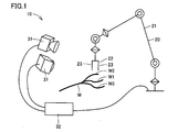
- the overall system 10 for carrying out the linear object gripping method includes a robot 20, a three-dimensional camera 31, and a control device 32.
- a wire harness W composed of an electric wire W1, an electric wire W2, and an electric wire W3 is disposed.
- a robot hand 22 is provided at the tip of the robot arm 21, and a linear object is gripped by a pair of gripping portions 23, 23 of the robot hand.
- the three-dimensional camera 31 is not particularly limited as long as it can measure the three-dimensional shape of the electric wire W1, the electric wire W2, and the electric wire W3.
- a stereo camera is preferably used.
- the stereo camera is preferable for measuring the three-dimensional shape of the linear object at high speed.
- the stereo camera includes two cameras, and finds corresponding points of points to be measured on two images taken from different viewpoints, and determines the three-dimensional measurement points based on the principle of triangulation from the positional relationship of the two cameras. Calculate the position.
- Japanese Patent Laid-Open No. 2-309202 discloses that a large number of linear objects are picked up by two cameras, and the inclination of the bright lines in the two images and the distance between the bright lines are measured. It is described that the corresponding point is determined by collating the distances as features, and the processing time for determining the corresponding point can be shortened.
- a straight line obtained by projecting a line connecting the viewpoint of one image and a measurement point onto the other image is called an epipolar line, and the other line corresponding to the point on one image The corresponding point on the image is always projected on the epipolar line on the other image.
- the corresponding point of a certain point on the linear object can be obtained by finding the intersection of the linear object and the epipolar line on the other image, and the three-dimensional shape of the linear object can be obtained at high speed. Can be measured. If the linear objects are color-coded in different colors, the color camera can be used to extract the corresponding color from the image and then obtain the corresponding points, thereby making the three-dimensional shape of each linear object faster. Can be requested.
- the control device 32 communicates with the three-dimensional camera 31 through a communication unit (not shown), and acquires the three-dimensional shapes of the electric wire W1, the electric wire W2, and the electric wire W3 from the stereo camera.
- the control device determines whether or not the robot hand 22 interferes with another linear object when the robot hand 22 grips the linear object, based on the three-dimensional shape acquired from the stereo camera, by an arithmetic unit (not shown). Various calculations are performed to determine the target linear object.
- the control device notifies the robot 20 of the gripping position of the target linear object to be gripped based on the calculation result via the communication unit.
- another device for example, a robot controller or a control personal computer for controlling the operation of the robot is provided between the control device 32 and the robot 20. Notification may be made.
- the related-art linear object gripping method includes a step (S1) of measuring a three-dimensional shape of a plurality of electric wires W1, electric wires W2, and electric wires W3, and the robot hand 22 detects a linear object based on the measured three-dimensional shape.
- the step S1 for measuring the three-dimensional shape of the plurality of electric wires W1, the electric wires W2, and the electric wires W3 is performed by the three-dimensional camera 31.
- the stereo camera captures a work space with a linear object, and performs arithmetic processing on the two images to acquire the three-dimensional shapes of the electric wires W1, W2, and W3.
- the three-dimensional shape of the linear object is represented by an orthogonal coordinate system or an oblique coordinate system, and is preferably represented by an orthogonal coordinate.
- Determination step S2 is performed by the control device 32. Details of the determination step will be described later.
- the step S3 for gripping the target linear object is performed by the robot 20.
- the robot is notified of the gripping position of the target linear object to be gripped from the control device 32, and moves the robot arm 21 and the robot hand 22 to execute a gripping operation.
- the determination step S2 will be described in detail below. Referring to FIG. 3, in the determination step S2 of the related technology, the three-dimensional shape of the linear object is acquired (S21), the target linear object is selected (S22), and the grip position of the target linear object is determined (S23). ), Obtaining the robot hand standby position (S24), setting various interference areas (S51 to S54), and various interference determinations (S61 to S64).
- control device 32 acquires the three-dimensional shapes of the electric wires W1, W2, and W3 from the three-dimensional camera 31 (S21).
- the control device 32 selects a line-of-interest to be gripped by the robot hand 22 (S22).
- the wire of interest W1, the wire W2 and the wire W3, which are intended to grip the electric wire W1 will be described as a wire (other wire) other than the wire of interest.
- the control device may receive a designation such as the color of the electric wire from the outside and determine the target linear object based on the instruction.
- the control device autonomously selects the line-of-interest (see Japanese Patent Application No. 2017-221405).
- the highest position that is, the uppermost linear object is selected as the attention linear object based on the acquired three-dimensional shape. Can do. This is because even when linear objects are placed in an overlapping manner, the higher the linear object, the lower the probability that another linear object will interfere when the linear object is gripped.
- the control device 32 determines a gripping position of the wire W1 to be noted (S23). For example, based on a predetermined condition such as how many mm from the tip of the noticeable linear object, the control device calculates the grip position of the noticeable linear object as three-dimensional coordinates.
- the control device 32 acquires the standby position of the robot hand 22 (S24). If the standby position of the robot hand 22 is predetermined, the coordinates are acquired as the standby position. When the standby position is determined based on the three-dimensional shape of the linear object, for example, when it is determined above a predetermined distance from the linear object, the standby position is obtained by calculation.
- the control device 32 acquires the current position of the robot hand 22 from the robot 20 and moves the robot hand 22 to the standby position when the current position of the robot hand 22 is different from the standby position.
- a line segment connecting the standby position of the robot hand 22 and the gripping position of the electric wire W1 provides an approximate movement path when the robot hand 22 executes the gripping operation.
- the control device 32 sets several interference areas including the gripping position of the target linear object in order to determine the interference between the robot hand 22 and the other electric wires W2 and W3.
- the first interference area, the first extended interference area, the second interference area, and the second extended interference area are set in this order.
- interference determination is performed to determine whether or not the other linear object is included in each of the interference regions.
- Interference judgment for each linear object is to determine whether the point is in the interference area or whether the line segment intersects the interference area while shifting the point or line segment on the linear object in the length direction. Can be done.
- the second preliminary determination for the second extended interference region, the second determination for the second interference region, the first preliminary determination for the first extended interference region, and the first determination for the first interference region are performed in this order.
- each interference region and interference determination for the region will be described.
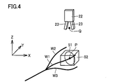
- the robot hand 22 in the first determination step S61 for the first interference region 51, it is determined whether or not the robot hand 22 interferes with the other electric wires W2 and W3 when holding the electric wire W1.
- the first interference area 51 is a planar area including the gripping position P of the electric wire W1 and having a predetermined shape and a predetermined size.
- the first interference region preferably includes the grip position P at the center thereof.
- the shape of the first interference region is not particularly limited, but is preferably a polygon, a circle, or an ellipse. When the first interference region is a polygon, it is preferably a quadrangle, more preferably a square. This is because the calculation load is reduced and high-speed determination is possible.
- the first interference region is a polygon
- a square having sides parallel to a plane formed by any two axes of a coordinate system (hereinafter simply referred to as a “coordinate system”) representing the three-dimensional shape of the linear object is
- coordinate system a coordinate system representing the three-dimensional shape of the linear object
- the efficiency of the first preliminary determination can be improved by reducing the first extended interference region described later. If the first interference area is not a polygon, it is preferably a circle. Similarly, the calculation load is reduced and high-speed determination is possible.
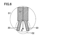
- the first interference region is preferably included in a circle having a diameter 2.0 times that of the circle C1. More preferably, the size is contained in a circle having the same size as the circle C1.
- the first interference region is preferably a circle C2. It is a size that can contain a circle of the same size as that of Japanese Patent Application No. 2017-221405.
- the first interference region 51 is preferably orthogonal to the electric wire W1. That the first interference region is orthogonal to the target linear object means that the direction in which the target linear object extends at the gripping position P is perpendicular to the first interference region. This is because a plane equation including the first interference region can be easily obtained.
- the linear object is often gripped from the side, that is, from a direction perpendicular to the linear object. If there is another linear object in the first interference region orthogonal to the target linear object, even if the robot hand 22 does not grip the target linear object from the side, the robot hand 22 This is because there is a high probability of interference with the linear object.
- the first determination step S ⁇ b> 61 can be performed by determining the intersection of the line segment L on the other target electric wire W ⁇ b> 2 and the first interference region 51.
- the line segment L can be a line segment between two adjacent points S and T in the point group representing the three-dimensional shape of the electric wire W2. If the line segment L intersects the first interference area, some point on the line segment L is included in the first interference area.
- the intersection determination can be performed by a known method. For example, when the inner product of the normal vector N of the plane U including the first interference region 51 and the vectors PS and PT from the gripping position P to both ends S and T of the line segment L is taken, the signs of the two inner products are different.
- the line segment L intersects the plane U. When the line segment L and the plane U intersect, it may be determined whether or not the intersection is in the first interference region 51.
- the first preliminary determination step S62 for the first extended interference region 52 is performed prior to the first determination, and faster calculation is performed when the robot hand 22 does not interfere with the other electric wires W2, W3. To find out.
- the first extended interference region 52 is a spatial region that includes the first interference region 51.
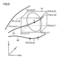
- the shape and size of the first extended interference region are not particularly limited, but preferably the smallest one of the hexahedrons including the first interference region and having all sides parallel to any axis of the coordinate system is the first. Set as one extended interference area.
- the coordinate system is an orthogonal coordinate system
- the hexahedron is a rectangular parallelepiped.
- the coordinates of the eight vertices A to H of the first extended interference region 52 are as shown in FIG. 8, and the coordinates of one end point S of the line segment L are (xS, yS, zS), if x1 ⁇ xS ⁇ x2, y1 ⁇ yS ⁇ y2, and z1 ⁇ zS ⁇ z2, the point S is in the first extended interference region; otherwise, the point S is 1 Outside the extended interference area.
- the first determination can be omitted if the result of the first preliminary determination indicates that the hand and other linear objects do not interfere with each other.
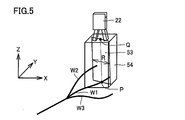
- the second interference region 53 is a planar region that includes a line segment PQ that connects the gripping position P of the electric wire W1 and the standby position Q of the robot hand 22, and has a predetermined width extending on both sides of the line segment PQ.
- the second interference region preferably includes a line segment PQ at the center in the width direction.
- the shape of the second interference region is not particularly limited, but is preferably a rectangle or a parallelogram, and more preferably a rectangle having a line segment PQ as an axis of symmetry of line symmetry. This is because the calculation load is reduced and the determination is made at a higher speed.
- the width of the second interference region 53 is preferably equal to or smaller than the diameter of the circle C1 in FIG.
- the width of the second interference region is preferably equal to or larger than the diameter of the circle C2 in FIG.
- the second interference region 53 is preferably set so that the intersection angle with the electric wire W1 is maximized. This is because, when the robot hand 22 approaches the electric wire W1, the gripping portions 23 and 23 often travel in such a plane.
- 2nd determination process S63 can be performed by the intersection determination of the line segment L on the other electric wire W2 made into object, and the 2nd interference area
- the second preliminary determination step (S64) for the second extended interference area 54 is performed prior to the second determination, and the case where the robot hand 22 does not interfere with the other electric wires W2 and W3 is found by faster calculation. To do.
- the second extended interference area 54 is a spatial area that includes the second interference area 53.
- the shape and size of the second extended interference region are not particularly limited, but preferably the smallest one of the hexahedrons including the second interference region and having all sides parallel to any axis of the coordinate system is the second. 2 Set as an extended interference area.
- the coordinate system is an orthogonal coordinate system
- the hexahedron is a rectangular parallelepiped. Thereby, the second preliminary determination can be performed only by comparing the size of the coordinates.
- the second determination can be omitted when the second preliminary determination shows that the hand and other linear objects do not interfere with each other.
- the control device 32 interferes with other linear objects when the robot hand 22 holds the holding position of the electric wire W1. Judge that there is no. Then, the electric wire W1 is set as the target linear object, and the grip position is notified to the robot 20.
- the control device 32 grips the gripping position of the electric wire W1 with the robot hand 22. It is determined that there is interference from other linear objects. The subsequent determination process is omitted, and the process returns to step S22, and the same processing is repeated while changing the target linear object.
- the control device 32 autonomously selects the next linear object of interest, for example, based on the three-dimensional shape of the electric wires W1 to W3 previously obtained from the three-dimensional camera 31, the linear object at the next higher position is used. An object can be selected as a noticeable linear object.
- each step may be performed again after changing the positional relationship between the linear objects.
- the distance from the gripping position of each target linear object to the nearest other linear object may be calculated as the interference distance, and the linear object having a long interference distance may be gripped.
- the interference distance can be easily calculated by using the distance from the intersection between the first interference region or the second interference region and another linear object in the interference determination to the gripping position.
- the presence or absence of interference with other linear objects of the robot hand 22 is implemented by calculating the presence or absence of intersection with the polyhedron using the CAD data on the robot hand 22 side and the three-dimensional shape data of the linear object. Also good. However, this method is excellent in accuracy of determination, but is a time-consuming process.
- whether or not a linear object other than the target linear object exists in the first interference region can be determined by the intersection determination between the planar first interference region and the linear object. And the presence or absence of interference can be determined at high speed. When there is no linear object other than the target linear object in the first interference region, there is a high probability that the robot hand 22 can grip the target linear object without interfering with other linear objects. The same applies to the second interference region.
- each determination step is not particularly limited, except that the first preliminary determination is performed prior to the first determination and the second preliminary determination is performed prior to the second determination.
- the 1st determination process was implemented after the 2nd determination process first, you may reverse this order.
- all determination processes are performed for each line segment while shifting the line segment L in the length direction of the linear object.
- one determination process for example, the second preliminary determination
- another determination step for example, a second determination step
- the attention linear object is selected prior to the acquisition of the standby position of the robot hand 22 (S24) (S22), but the standby position of the robot hand 22 is acquired first, and the attention line is based on the standby position.
- a shape may be selected.
- the linear object that is closest to the standby position can be selected as the target linear object.
- a linear object having the shortest distance between the coordinates of the standby position and the coordinates of the gripping position of the linear object may be selected. This is preferable in that a linear object that is unlikely to interfere with other linear objects can be preferentially selected when gripped.
- the posture (gripping posture) when the robot hand 22 grips the linear object is preferably gripped so that the grip portion and the linear object are substantially perpendicular. This is because if the orientation of the linear object from the gripping position to the gripping portion is substantially perpendicular to the gripping part, the robot can be easily controlled even when it is inserted into a processing machine after gripping.
- the posture of the robot hand 22 is adjusted so that the gripping portion and the linear object are oriented at right angles when gripped. Thereafter, the robot hand 22 moves along the second interference region from the standby position toward the gripping position. Thereby, since the posture of the robot hand 22, the moving direction of the robot hand 22, and the orientation of the planes of the first and second interference areas coincide, it is possible to perform highly accurate interference determination.
- the robot hand 22 holding the linear object according to the present invention may convey the linear object to various manufacturing apparatuses and processing apparatuses.
- the tip of the gripped electric wire may be moved by the robot hand 22 and inserted into a film peeling machine or a terminal crimping device. You may use for the process of inserting the front-end
- the control device 32 acquires the three-dimensional shape of the linear object W1 from the three-dimensional camera 31 that acquires the three-dimensional shape of the linear object W1, acquires the position of the tip of the linear object W1 from the three-dimensional shape, It is assumed that information for moving the tip W1s to the target position is notified to the robot 20 having the robot hand 22 based on the position of the tip W1s of the linear object W1.
- the control device 32 may be any of a control device independent of the robot 20 and the three-dimensional camera 31, a control device provided in the robot 20, and a control device provided in the three-dimensional camera 31.
- the posture (gripping posture) when the robot hand 22 grips the linear object is preferably gripped so that the grip portion and the linear object are substantially perpendicular.
- a linear object having a certain degree of flexibility it is assumed that the tip side of the linear object gripped by the robot hand 22 does not extend straight but is bent.
- control device 32 measures the direction of the tip of the linear object from the three-dimensional shape of the linear object, and matches the direction of the tip of the linear object with a predetermined direction to move the information to the target position.
- the robot having the robot hand may be notified.
- a method for measuring the amount of bending of the tip of a linear object when the linear object is conveyed to a predetermined position by the robot hand 22 holding the linear object will be described below.
- a case where the tip W1s of the electric wire W1 is inserted as a linear object into the hole TGH provided in the target TG will be described as an example of conveyance to a predetermined position.
- the diameter of the linear object may be in a range that can be recognized by a three-dimensional camera, and is preferably 0.01 mm to 10 cm.
- the hole TGH provided in the target TG has only to have a size capable of inserting a linear object, and preferably has a diameter of 0.01 mm to 15 cm and a hole depth of at least twice the diameter of the linear object. preferable.
- FIG. 9 a state in which the electric wire W1 is gripped by the robot hand 22 is shown. Furthermore, the tip W1s of the electric wire W1 is not extended so as to be substantially perpendicular to the robot hand 22, but is bent.
- the tip W1s of the electric wire W1 gripped by the robot hand 22 Measure the position of the tip W1s of the electric wire W1 gripped by the robot hand 22.
- the tip bending amount of how much the tip W1s of the electric wire W1 is shifted from L1 may be measured.
- the three-dimensional shape can be measured using the three-dimensional camera 31 described above. As a result, the position of the tip W1s and the displacement amount X1 can be known.
- the extending direction of the tip of the electric wire W1 can be determined by measuring the shape from the tip W1s of the electric wire W1 to a predetermined distance position (distance D1 in FIG. 9) and obtaining an average vector.
- the direction of the tip may be a vector connecting the tip W1s of the electric wire W1 and the position of the insertion length from the tip W1s to the hole.
- the predetermined distance position (distance D1 in FIG. 9) from the tip W1s of the electric wire W1 is preferably 0.3 to 10 times the hole depth of the hole TGH provided in the target TG, more preferably 0.5 to 5 Is double.
- the amount of bending from the tip may be measured, and a point up to a sharp change may be set as D1.
- the position and the tip bending amount are fed back to the movement control of the robot hand 22.
- the tip W1s can be moved to the hole TGH provided in the target TG by giving a feedback amount from the position of the tip W1s and the tip bending amount.
- the hole depth of the hole TGH is shallow, there is little problem.
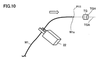
- the direction of the tip W1s is made to coincide with a predetermined direction so that the electric wire can be inserted into the hole.
- a near position P11 located on the extension line of the center axis TG-A of the hole TGH is determined in advance, the tip W1s is moved to the near position P11, and the center axis TG- of the hole TGH is set. Movement is performed so that the direction A matches the direction of the tip of the electric wire W1.
- the moving method may be to match the direction while moving the tip W1s to the near position P11, or after moving the tip W1s to the near position and then rotating the electric wire W1 to match the direction at the near position.
- the near position is preferably near the target position, and when the target position is a hole, it is preferably on a line extending the central axis of the hole. When the target position is a groove, it is preferable to be directly above the groove. When the target position is a terminal block, it is preferable that the target position is on a line extending in a direction in which the terminals are connected from a position where the terminals are connected.
- the tip W1s is moved into the hole TGH even when the hole TGH is deep or the hole TGH has a small diameter. It becomes possible to let it pass through.
- the electric wire W1 it is judged by a sensor or the like whether or not the electric wire W1 has been inserted into the hole TGH. If the insertion has failed, the electric wire W1 is returned to the front position P11 and the position and orientation of the tip W1s of the electric wire W1 are measured again. Then, the tip W1s may be moved to the hole TGH by matching the direction in which the central axis TG-A of the hole TGH extends and the direction of the tip of the electric wire W1.
- the relative coordinates of the tip of the rod B can be calculated from the robot hand 22. This is held as reference data, for example, P1.
- the tip position of the rod when moved is the target position.
- the target position may be set in the hole or may be set near the entrance of the hole.
- the coordinates of the tip of the moved bar in the robot coordinate system are registered as the target position. This can be calculated by adding P1 to the coordinates of the robot hand. This position is registered as P0. This completes teaching of the target position.
- the robot hand 22 grips the electric wire W1 to be moved. Thereafter, the electric wire W1 is scanned with a three-dimensional camera.
- the relative coordinates from the robot hand 22 to the tip W1s of the electric wire W1 can be calculated. If this is P2, for example, the vector calculated in P0-P2 is notified to the robot as a movement vector, and the robot moves the electric wire.
- the tip W1s may be moved along a line extending the central axis TG-A. Further, without defining the near position P11, the wire W1 may be moved from the initial position to the hole TGH while being rotated so that the extending direction of the tip of the electric wire W1 coincides with the extending direction of the central axis TG-A of the hole TGH. Any moving method that moves the tip W1s of the linear object W1 to a predetermined position so that the direction of the tip W1s matches a predetermined direction when the tip W1s reaches the target position P0 may be used.
- the linear object and the target position are limited to this. Not. Specific examples where the target position is a hole include an inspection device that inspects the tip of the wire, a wire stripper that strips the coating of the wire, a processing machine that connects the wire and the connector, and a processing device that crimps a crimp terminal on the tip of the wire. A predetermined position is mentioned.
- the present invention can be used as a solder where the linear object is a solder and the target position is a predetermined position of the substrate to be soldered or a position immediately above the predetermined position of the substrate.
- the present embodiment can be used by assuming that the linear object is an electric wire with a terminal, and the target position is a predetermined position or a vicinity of the predetermined position of the terminal block.
- the target position is not limited to the hole, and may be a predetermined inspection position, a processing work position, a surface or a groove, or a predetermined location in the vicinity thereof.
Landscapes
- Engineering & Computer Science (AREA)
- Mechanical Engineering (AREA)
- Robotics (AREA)
- Health & Medical Sciences (AREA)
- General Health & Medical Sciences (AREA)
- Orthopedic Medicine & Surgery (AREA)
- Human Computer Interaction (AREA)
- Multimedia (AREA)
- Manipulator (AREA)
Priority Applications (6)
| Application Number | Priority Date | Filing Date | Title |
|---|---|---|---|
| EP19756929.6A EP3756835A4 (en) | 2018-02-23 | 2019-02-15 | LINEAR OBJECT POINT MOVEMENT PROCESS, CONTROL DEVICE AND THREE-DIMENSIONAL CAMERA |
| JP2020501732A JP7410849B2 (ja) | 2018-02-23 | 2019-02-15 | 線状物の先端移動方法、および、制御装置 |
| KR1020207027324A KR20200123816A (ko) | 2018-02-23 | 2019-02-15 | 선형물의 선단 이동 방법, 제어 장치, 및, 삼차원 카메라 |
| US16/971,679 US11964397B2 (en) | 2018-02-23 | 2019-02-15 | Method for moving tip of line-like object, controller, and three-dimensional camera |
| CN201980014602.3A CN111757796B (zh) | 2018-02-23 | 2019-02-15 | 线状物的前端移动方法、控制装置以及三维照相机 |
| KR1020237038610A KR20230159628A (ko) | 2018-02-23 | 2019-02-15 | 선형물의 선단 이동 방법, 및, 제어 장치 |
Applications Claiming Priority (2)
| Application Number | Priority Date | Filing Date | Title |
|---|---|---|---|
| JP2018031263 | 2018-02-23 | ||
| JP2018-031263 | 2018-02-23 |
Publications (1)
| Publication Number | Publication Date |
|---|---|
| WO2019163671A1 true WO2019163671A1 (ja) | 2019-08-29 |
Family
ID=67688100
Family Applications (1)
| Application Number | Title | Priority Date | Filing Date |
|---|---|---|---|
| PCT/JP2019/005611 WO2019163671A1 (ja) | 2018-02-23 | 2019-02-15 | 線状物の先端移動方法、制御装置、および、三次元カメラ |
Country Status (7)
| Country | Link |
|---|---|
| US (1) | US11964397B2 (zh) |
| EP (1) | EP3756835A4 (zh) |
| JP (1) | JP7410849B2 (zh) |
| KR (2) | KR20230159628A (zh) |
| CN (1) | CN111757796B (zh) |
| TW (1) | TWI760596B (zh) |
| WO (1) | WO2019163671A1 (zh) |
Cited By (1)
| Publication number | Priority date | Publication date | Assignee | Title |
|---|---|---|---|---|
| WO2022158604A1 (ja) * | 2021-01-25 | 2022-07-28 | 三菱電機株式会社 | ろう付け装置、ろう付け装置の制御方法およびプログラム |
Families Citing this family (1)
| Publication number | Priority date | Publication date | Assignee | Title |
|---|---|---|---|---|
| KR20230159628A (ko) * | 2018-02-23 | 2023-11-21 | 구라시키 보세키 가부시키가이샤 | 선형물의 선단 이동 방법, 및, 제어 장치 |
Citations (7)
| Publication number | Priority date | Publication date | Assignee | Title |
|---|---|---|---|---|
| JPH02309202A (ja) | 1989-05-23 | 1990-12-25 | Nippondenso Co Ltd | 位置測定装置 |
| WO1998017444A1 (fr) * | 1996-10-24 | 1998-04-30 | Fanuc Ltd | Systeme de robot de commande de forces a capteur optique pour travail d'insertion |
| JP2012200805A (ja) * | 2011-03-24 | 2012-10-22 | Canon Inc | ロボット制御装置、ロボット制御方法、プログラム及び記録媒体 |
| JP2014176917A (ja) | 2013-03-14 | 2014-09-25 | Yaskawa Electric Corp | ロボット装置 |
| JP2016192138A (ja) | 2015-03-31 | 2016-11-10 | 株式会社オートネットワーク技術研究所 | ワイヤーハーネスの製造方法および画像処理方法 |
| JP2017221045A (ja) | 2016-06-08 | 2017-12-14 | 日産自動車株式会社 | 電動車両の制御方法、及び電動車両の制御装置 |
| JP2017226029A (ja) * | 2016-06-20 | 2017-12-28 | キヤノン株式会社 | ロボット装置の制御方法、およびロボット装置 |
Family Cites Families (12)
| Publication number | Priority date | Publication date | Assignee | Title |
|---|---|---|---|---|
| WO2008047872A1 (fr) * | 2006-10-20 | 2008-04-24 | Hitachi, Ltd. | Manipulateur |
| CN101396829A (zh) | 2007-09-29 | 2009-04-01 | 株式会社Ihi | 机器人装置的控制方法以及机器人装置 |
| JP5448326B2 (ja) | 2007-10-29 | 2014-03-19 | キヤノン株式会社 | 把持装置および把持装置制御方法 |
| JP5528095B2 (ja) | 2009-12-22 | 2014-06-25 | キヤノン株式会社 | ロボットシステム、その制御装置及び方法 |
| JP4837116B2 (ja) * | 2010-03-05 | 2011-12-14 | ファナック株式会社 | 視覚センサを備えたロボットシステム |
| JP2011200948A (ja) | 2010-03-24 | 2011-10-13 | Sony Corp | 把持判別装置および把持判別方法 |
| US9041914B2 (en) | 2013-03-15 | 2015-05-26 | Faro Technologies, Inc. | Three-dimensional coordinate scanner and method of operation |
| JP6693098B2 (ja) | 2015-11-26 | 2020-05-13 | セイコーエプソン株式会社 | ロボット、及びロボットシステム |
| KR20230159628A (ko) * | 2018-02-23 | 2023-11-21 | 구라시키 보세키 가부시키가이샤 | 선형물의 선단 이동 방법, 및, 제어 장치 |
| JP6810173B2 (ja) * | 2019-01-29 | 2021-01-06 | 日本金銭機械株式会社 | 物体把持システム |
| JP7015265B2 (ja) * | 2019-03-14 | 2022-02-02 | ファナック株式会社 | コネクタを含むワークを把持する作業ツールおよび作業ツールを備えるロボット装置 |
| US20230124687A1 (en) * | 2021-10-14 | 2023-04-20 | Olympus Medical Systems Corp. | Method for calibrating endoscope and endoscope system |
-
2019
- 2019-02-15 KR KR1020237038610A patent/KR20230159628A/ko active Application Filing
- 2019-02-15 CN CN201980014602.3A patent/CN111757796B/zh active Active
- 2019-02-15 WO PCT/JP2019/005611 patent/WO2019163671A1/ja unknown
- 2019-02-15 KR KR1020207027324A patent/KR20200123816A/ko not_active IP Right Cessation
- 2019-02-15 JP JP2020501732A patent/JP7410849B2/ja active Active
- 2019-02-15 EP EP19756929.6A patent/EP3756835A4/en active Pending
- 2019-02-15 US US16/971,679 patent/US11964397B2/en active Active
- 2019-02-20 TW TW108105635A patent/TWI760596B/zh active
Patent Citations (7)
| Publication number | Priority date | Publication date | Assignee | Title |
|---|---|---|---|---|
| JPH02309202A (ja) | 1989-05-23 | 1990-12-25 | Nippondenso Co Ltd | 位置測定装置 |
| WO1998017444A1 (fr) * | 1996-10-24 | 1998-04-30 | Fanuc Ltd | Systeme de robot de commande de forces a capteur optique pour travail d'insertion |
| JP2012200805A (ja) * | 2011-03-24 | 2012-10-22 | Canon Inc | ロボット制御装置、ロボット制御方法、プログラム及び記録媒体 |
| JP2014176917A (ja) | 2013-03-14 | 2014-09-25 | Yaskawa Electric Corp | ロボット装置 |
| JP2016192138A (ja) | 2015-03-31 | 2016-11-10 | 株式会社オートネットワーク技術研究所 | ワイヤーハーネスの製造方法および画像処理方法 |
| JP2017221045A (ja) | 2016-06-08 | 2017-12-14 | 日産自動車株式会社 | 電動車両の制御方法、及び電動車両の制御装置 |
| JP2017226029A (ja) * | 2016-06-20 | 2017-12-28 | キヤノン株式会社 | ロボット装置の制御方法、およびロボット装置 |
Non-Patent Citations (1)
| Title |
|---|
| YASUO KITA, YUKIYASU DOMAE, HARUHISA OKUDA, MASANORI SEKI: "1B2-3 Development of robot vision system that can handle flexible objects", 29TH ANNUAL CONFERENCE OF THE ROBOTICS SOCIETY OF JAPAN [29.-NIHON-ROBOTTO-GAKKAI-GAKUJUTSU-KŌENKAI : SEPTEMBER 7 - 9, 2011, TŌKYŌ, JAPAN], 7 September 2011 (2011-09-07), XP009523360 * |
Cited By (2)
| Publication number | Priority date | Publication date | Assignee | Title |
|---|---|---|---|---|
| WO2022158604A1 (ja) * | 2021-01-25 | 2022-07-28 | 三菱電機株式会社 | ろう付け装置、ろう付け装置の制御方法およびプログラム |
| JP7471468B2 (ja) | 2021-01-25 | 2024-04-19 | 三菱電機株式会社 | ろう付け装置、ろう付け装置の制御方法およびプログラム |
Also Published As
| Publication number | Publication date |
|---|---|
| KR20230159628A (ko) | 2023-11-21 |
| US20200406466A1 (en) | 2020-12-31 |
| CN111757796B (zh) | 2023-09-29 |
| JP7410849B2 (ja) | 2024-01-10 |
| KR20200123816A (ko) | 2020-10-30 |
| TW201941888A (zh) | 2019-11-01 |
| EP3756835A4 (en) | 2021-12-15 |
| CN111757796A (zh) | 2020-10-09 |
| US11964397B2 (en) | 2024-04-23 |
| JPWO2019163671A1 (ja) | 2021-02-04 |
| TWI760596B (zh) | 2022-04-11 |
| EP3756835A1 (en) | 2020-12-30 |
Similar Documents
| Publication | Publication Date | Title |
|---|---|---|
| JP5685027B2 (ja) | 情報処理装置、物体把持システム、ロボットシステム、情報処理方法、物体把持方法およびプログラム | |
| JP5854815B2 (ja) | 情報処理装置、情報処理装置の制御方法、およびプログラム | |
| JP5778311B1 (ja) | ピッキング装置およびピッキング方法 | |
| JP2016099257A (ja) | 情報処理装置及び情報処理方法 | |
| Herakovic | Robot vision in industrial assembly and quality control processes | |
| WO2019163671A1 (ja) | 線状物の先端移動方法、制御装置、および、三次元カメラ | |
| US11816754B2 (en) | Measurement parameter optimization method and device, and computer control program stored on computer-readable storage medium | |
| JP7106571B2 (ja) | 線状物把持方法および制御装置 | |
| JP7177639B2 (ja) | 帯状物の3次元計測方法および帯状物の3次元計測装置 | |
| JP7454132B2 (ja) | ロボットシステムの制御装置、ロボットシステムの制御方法、コンピュータ制御プログラム、及びロボットシステム | |
| JP7140826B2 (ja) | 把持制御装置 | |
| JP7222720B2 (ja) | 先端部材位置推定方法、先端部材把持方法、先端部材接続方法、先端部材位置推定システム、および、先端部材把持システム | |
| JP2007125653A (ja) | ロボットハンドの把持制御装置 | |
| JP7217109B2 (ja) | 帯状物の作業位置決定方法、ロボット制御方法、帯状物の作業位置決定装置および帯状物ハンドリングシステム | |
| JP2021028107A (ja) | コネクタの向きの探索方法、コネクタの接続方法、ロボットハンド、制御装置、撮像装置、およびコネクタ接続システム | |
| WO2021149429A1 (ja) | ロボットシステムの制御装置、ロボットシステムの制御方法、コンピュータ制御プログラム、及びロボットシステム | |
| EP3871842A1 (en) | System and method for member articulation | |
| WO2020050121A1 (ja) | 帯状物の作業位置決定方法、ロボット制御方法、帯状物の作業位置決定装置、帯状物ハンドリングシステム、帯状物の3次元計測方法および帯状物の3次元計測装置 | |
| TWI839380B (zh) | 帶狀物的作業位置決定方法、機器人控制方法、帶狀物的作業位置決定裝置、帶狀物處理系統、帶狀物的三維測量方法及帶狀物的三維測量裝置 | |
| JP7438734B2 (ja) | 先端部材の向き認識方法、先端部材向き合わせ方法、先端部材挿入方法、先端部材向き認識装置及び先端部材向き合わせシステム | |
| JP2022150024A (ja) | ワーク把持方法、ロボット制御装置およびワーク把持システム |
Legal Events
| Date | Code | Title | Description |
|---|---|---|---|
| 121 | Ep: the epo has been informed by wipo that ep was designated in this application |
Ref document number: 19756929 Country of ref document: EP Kind code of ref document: A1 |
|
| ENP | Entry into the national phase |
Ref document number: 2020501732 Country of ref document: JP Kind code of ref document: A |
|
| NENP | Non-entry into the national phase |
Ref country code: DE |
|
| ENP | Entry into the national phase |
Ref document number: 20207027324 Country of ref document: KR Kind code of ref document: A |
|
| ENP | Entry into the national phase |
Ref document number: 2019756929 Country of ref document: EP Effective date: 20200923 |