本発明に基づいた実施の形態の先端曲り量計測方法について、以下、図を参照しながら説明する。以下に説明する実施の形態において、個数、量などに言及する場合、特に記載がある場合を除き、本発明の範囲は必ずしもその個数、量などに限定されない。同一の部品、相当部品に対しては、同一の参照番号を付し、重複する説明は繰り返さない場合がある。実施の形態における構成を適宜組み合わせて用いることは当初から予定されていることである。図においては、実際の寸法比率では記載しておらず、構造の理解を容易にするために、一部比率を異ならせて記載している。
The tip bending amount measuring method according to the embodiment of the present invention will be described below with reference to the drawings. In the embodiments described below, when referring to the number, amount, and the like, the scope of the present invention is not necessarily limited to the number, amount, and the like unless otherwise specified. The same parts and corresponding parts are denoted by the same reference numerals, and redundant description may not be repeated. It is planned from the beginning to use the structures in the embodiments in appropriate combinations. In the drawings, the actual dimensional ratios are not described, and some ratios are described in order to facilitate understanding of the structure.
以下の説明においては、線状物の一例として電線を用いた場合について説明しているが、電線に限定されるものではない。この説明での線状物とは、細長い形状を有する物体であれば何でもよい。線状物の一例としては、電線、ワイヤーハーネス、はんだ、紐、糸、繊維、ガラス繊維、光ファイバ、チューブ、乾麺等が挙げられる。細線を束にした電線に限定されず、一本線から構成される電線等も含まれる。特に、たわみが生じるなどして形状が変化する線状物や、直線ではない線状物の場合、本実施の形態の効果がより顕著に表れる。
In the following description, a case where an electric wire is used as an example of a linear object is described, but the present invention is not limited to an electric wire. The linear object in this description may be anything as long as it has an elongated shape. As an example of a linear thing, an electric wire, a wire harness, solder, a string, a thread | yarn, a fiber, glass fiber, an optical fiber, a tube, dry noodles, etc. are mentioned. It is not limited to the electric wire which bundled the thin wire, The electric wire etc. which consist of a single wire are also included. In particular, in the case of a linear object whose shape changes due to deflection or a linear object that is not a straight line, the effect of the present embodiment appears more remarkably.
(関連技術:線状物把持方法および制御装置)
以下、図1から図8を参照して、関連技術として、線状物把持方法および制御装置の一例について説明する。
(Related technology: Linear object gripping method and control device)
Hereinafter, an example of a linear object gripping method and a control device will be described as a related technique with reference to FIGS.
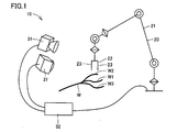
図1において、線状物把持方法を実施するための全体システム10は、ロボット20と、三次元カメラ31と、制御装置32とを有する。作業空間には、電線W1、電線W2、電線W3から構成されるワイヤーハーネスWが配置されている。
1, the overall system 10 for carrying out the linear object gripping method includes a robot 20, a three-dimensional camera 31, and a control device 32. In the work space, a wire harness W composed of an electric wire W1, an electric wire W2, and an electric wire W3 is disposed.
ロボット20としては、公知の多関節ロボットを好適に利用することができる。ロボットのアーム21の先端にはロボットハンド22が備えられており、ロボットハンドの一対の把持部23、23で線状物を把持する。
As the robot 20, a known articulated robot can be suitably used. A robot hand 22 is provided at the tip of the robot arm 21, and a linear object is gripped by a pair of gripping portions 23, 23 of the robot hand.
三次元カメラ31は、電線W1、電線W2、電線W3の三次元形状を計測できるものであれば特に限定されない。好ましくはステレオカメラを用いる。ステレオカメラは線状物の三次元形状を高速に計測するのに好ましい。
The three-dimensional camera 31 is not particularly limited as long as it can measure the three-dimensional shape of the electric wire W1, the electric wire W2, and the electric wire W3. A stereo camera is preferably used. The stereo camera is preferable for measuring the three-dimensional shape of the linear object at high speed.
ステレオカメラは2台のカメラを含み、異なる視点から撮像された2枚の画像上で計測したい点の対応点を求め、2台のカメラの位置関係から3角測量の原理によって計測点の三次元位置を算出する。ステレオ方式による線状物の三次元計測に関しては、たとえば、特開平2-309202号公報には、多数の線状物を2台のカメラで撮像し、2つの画像中の輝線の傾きと輝線間の距離を特徴として照合することにより対応点を決定することが記載されており、これによって、対応点の決定にかかる処理時間を短縮できるとされる。
The stereo camera includes two cameras, and finds corresponding points of points to be measured on two images taken from different viewpoints, and determines the three-dimensional measurement points based on the principle of triangulation from the positional relationship of the two cameras. Calculate the position. Regarding the three-dimensional measurement of a linear object by the stereo method, for example, Japanese Patent Laid-Open No. 2-309202 discloses that a large number of linear objects are picked up by two cameras, and the inclination of the bright lines in the two images and the distance between the bright lines are measured. It is described that the corresponding point is determined by collating the distances as features, and the processing time for determining the corresponding point can be shortened.
ステレオ方式において、一方の画像の視点と計測点を結ぶ直線を他方の画像上に(特願2017―221045号参照)投影した直線をエピポーラ線といい、一方の画像上の点に対応する他方の画像上の対応点は必ず他方の画像上のエピポーラ線上に投影されている。
In the stereo system, a straight line obtained by projecting a line connecting the viewpoint of one image and a measurement point onto the other image (see Japanese Patent Application No. 2017-221405) is called an epipolar line, and the other line corresponding to the point on one image The corresponding point on the image is always projected on the epipolar line on the other image.
このことを利用して、線状物の上のある点の対応点を求めるには、他方の画像上で線状物とエピポーラ線の交点を求めればよく、高速に線状物の三次元形状を計測できる。線状物が互いに異なる色に色分けされている場合には、カラーカメラを用いることにより、画像から該当する色を抽出してから対応点を求めることで、各線状物の三次元形状をより高速に求めることができる。
Using this, the corresponding point of a certain point on the linear object can be obtained by finding the intersection of the linear object and the epipolar line on the other image, and the three-dimensional shape of the linear object can be obtained at high speed. Can be measured. If the linear objects are color-coded in different colors, the color camera can be used to extract the corresponding color from the image and then obtain the corresponding points, thereby making the three-dimensional shape of each linear object faster. Can be requested.
制御装置32は、図示しない通信部によって三次元カメラ31と通信し、ステレオカメラから電線W1、電線W2、電線W3の三次元形状を取得する。制御装置は図示しない演算部によって、ステレオカメラから取得した三次元形状に基づいて、ロボットハンド22が線状物を把持する際に他の線状物と干渉するか否かを判定し、把持すべき目標線状物を決定するための各種演算を行なう。
The control device 32 communicates with the three-dimensional camera 31 through a communication unit (not shown), and acquires the three-dimensional shapes of the electric wire W1, the electric wire W2, and the electric wire W3 from the stereo camera. The control device determines whether or not the robot hand 22 interferes with another linear object when the robot hand 22 grips the linear object, based on the three-dimensional shape acquired from the stereo camera, by an arithmetic unit (not shown). Various calculations are performed to determine the target linear object.
制御装置は上記通信部を介して、演算結果に基づいて、把持すべき目標線状物の把持位置をロボット20に通知する。把持位置をロボット20に直接通知するだけでなく、制御装置32とロボット20との間にロボットの動作を制御する別の装置(たとえば、ロボットコントローラや制御用パソコン等)を設け、それらの装置に対して通知しても良い。
The control device notifies the robot 20 of the gripping position of the target linear object to be gripped based on the calculation result via the communication unit. In addition to notifying the gripping position directly to the robot 20, another device (for example, a robot controller or a control personal computer) for controlling the operation of the robot is provided between the control device 32 and the robot 20. Notification may be made.
図2を参照して、本関連技術の線状物把持方法を以下に説明する。この関連技術の線状物把持方法は、複数の電線W1、電線W2、電線W3の三次元形状を計測する工程(S1)、計測された三次元形状に基づいてロボットハンド22が線状物を把持する際に他の線状物が干渉するか否かを判定する判定工程(S2)、判定工程S2における判定結果に基づいて決定された目標線状物を把持する工程(S3)を含む。
Referring to FIG. 2, the linear object gripping method of the related technology will be described below. The related-art linear object gripping method includes a step (S1) of measuring a three-dimensional shape of a plurality of electric wires W1, electric wires W2, and electric wires W3, and the robot hand 22 detects a linear object based on the measured three-dimensional shape. A determination step (S2) for determining whether or not another linear object interferes when gripping, and a step (S3) for gripping the target linear object determined based on the determination result in the determination step S2.
複数の電線W1、電線W2、電線W3の三次元形状を計測する工程S1は三次元カメラ31によって実施される。ステレオカメラは線状物のある作業空間を撮像し、2枚の画像を演算処理して電線W1、電線W2、電線W3のそれぞれの三次元形状を取得する。線状物の三次元形状は、直交座標系または斜交座標系で表され、好ましくは直交座標で表される。
The step S1 for measuring the three-dimensional shape of the plurality of electric wires W1, the electric wires W2, and the electric wires W3 is performed by the three-dimensional camera 31. The stereo camera captures a work space with a linear object, and performs arithmetic processing on the two images to acquire the three-dimensional shapes of the electric wires W1, W2, and W3. The three-dimensional shape of the linear object is represented by an orthogonal coordinate system or an oblique coordinate system, and is preferably represented by an orthogonal coordinate.
判定工程S2は制御装置32によって実施される。判定工程については詳細を後述する。
Determination step S2 is performed by the control device 32. Details of the determination step will be described later.
目標線状物を把持する工程S3はロボット20によって実施される。ロボットは、把持すべき目標線状物の把持位置を制御装置32から通知され、ロボットアーム21およびロボットハンド22を移動させて把持動作を実行する。
The step S3 for gripping the target linear object is performed by the robot 20. The robot is notified of the gripping position of the target linear object to be gripped from the control device 32, and moves the robot arm 21 and the robot hand 22 to execute a gripping operation.
以下に判定工程S2を詳細に説明する。
図3を参照して、本関連技術の判定工程S2では、線状物の三次元形状の取得(S21)、注目線状物の選択(S22)、注目線状物の把持位置の決定(S23)、ロボットハンド待機位置の取得(S24)、各種干渉領域の設定(S51~S54)と各種干渉判定(S61~S64)を実施する。
The determination step S2 will be described in detail below.
Referring to FIG. 3, in the determination step S2 of the related technology, the three-dimensional shape of the linear object is acquired (S21), the target linear object is selected (S22), and the grip position of the target linear object is determined (S23). ), Obtaining the robot hand standby position (S24), setting various interference areas (S51 to S54), and various interference determinations (S61 to S64).
制御装置32はまず、三次元カメラ31から電線W1、電線W2、電線W3の三次元形状を取得する(S21)。
First, the control device 32 acquires the three-dimensional shapes of the electric wires W1, W2, and W3 from the three-dimensional camera 31 (S21).
次に、制御装置32は、ロボットハンド22で把持しようとする注目線状物を選択する(S22)。以下において、電線W1を把持しようとする注目線状物、電線W2と電線W3を注目線状物以外の線状物(他の線状物)として説明する。制御装置は、電線の色などの指定を外部から受けて、その指示に基づいて注目線状物を決定してもよい。好ましくは、制御装置は自律的(特願2017―221045号参照)に注目線状物を選択する。
Next, the control device 32 selects a line-of-interest to be gripped by the robot hand 22 (S22). In the following description, the wire of interest W1, the wire W2 and the wire W3, which are intended to grip the electric wire W1, will be described as a wire (other wire) other than the wire of interest. The control device may receive a designation such as the color of the electric wire from the outside and determine the target linear object based on the instruction. Preferably, the control device autonomously selects the line-of-interest (see Japanese Patent Application No. 2017-221405).
たとえば、電線W1、電線W2、電線W3が台の上に置かれている場合、取得した三次元形状に基づいて最も高い位置、すなわち最も上にある線状物を注目線状物として選択することができる。線状物が重なり合って置かれている場合でも、上にある線状物ほど、その線状物を把持するときに他の線状物が干渉する確率が低いからである。
For example, when the electric wire W1, the electric wire W2, and the electric wire W3 are placed on a table, the highest position, that is, the uppermost linear object is selected as the attention linear object based on the acquired three-dimensional shape. Can do. This is because even when linear objects are placed in an overlapping manner, the higher the linear object, the lower the probability that another linear object will interfere when the linear object is gripped.
次に、制御装置32は、注目すべき電線W1の把持位置を決定する(S23)。たとえば、注目線状物の先端から何mmというような予め定められた条件に基づいて、制御装置が注目線状物の把持位置を三次元座標として算出する。
Next, the control device 32 determines a gripping position of the wire W1 to be noted (S23). For example, based on a predetermined condition such as how many mm from the tip of the noticeable linear object, the control device calculates the grip position of the noticeable linear object as three-dimensional coordinates.
次に、制御装置32は、ロボットハンド22の待機位置を取得する(S24)。ロボットハンド22の待機位置が予め定められている場合は、その座標を待機位置として取得する。待機位置を線状物の三次元形状に基づいて決定する場合、たとえば線状物から所定距離離れた上方に決定するなどの場合は、演算により待機位置を取得する。
Next, the control device 32 acquires the standby position of the robot hand 22 (S24). If the standby position of the robot hand 22 is predetermined, the coordinates are acquired as the standby position. When the standby position is determined based on the three-dimensional shape of the linear object, for example, when it is determined above a predetermined distance from the linear object, the standby position is obtained by calculation.
制御装置32はロボットハンド22の現在位置をロボット20から取得し、ロボットハンド22の現在位置が待機位置と異なる場合は、ロボットハンド22を待機位置に移動させる。ロボットハンド22の待機位置と電線W1の把持位置を結ぶ線分が、ロボットハンド22が把持動作を実行するときのおおよその移動経路を与える。
The control device 32 acquires the current position of the robot hand 22 from the robot 20 and moves the robot hand 22 to the standby position when the current position of the robot hand 22 is different from the standby position. A line segment connecting the standby position of the robot hand 22 and the gripping position of the electric wire W1 provides an approximate movement path when the robot hand 22 executes the gripping operation.
次に、制御装置32は、ロボットハンド22と他の電線W2、電線W3との干渉判定のために、注目線状物の把持位置を含むいくつかの干渉領域を設定する。図3では、第1干渉領域、第1拡張干渉領域、第2干渉領域、第2拡張干渉領域の順に設定している。すべての他の線状物の1本毎に、当該他の線状物が上記それぞれの干渉領域に含まれるか否かを判定する干渉判定を行なう。
Next, the control device 32 sets several interference areas including the gripping position of the target linear object in order to determine the interference between the robot hand 22 and the other electric wires W2 and W3. In FIG. 3, the first interference area, the first extended interference area, the second interference area, and the second extended interference area are set in this order. For each one of all other linear objects, interference determination is performed to determine whether or not the other linear object is included in each of the interference regions.
各線状物についての干渉判定は、線状物上の点または線分を長さ方向にずらしながら、その点が干渉領域内にあるかまたはその線分が干渉領域と交差するかを判定することによって行なうことができる。図3では、第2拡張干渉領域に対する第2予備判定、第2干渉領域に対する第2判定、第1拡張干渉領域に対する第1予備判定、第1干渉領域に対する第1判定の順に実施している。以下に、図3の順番とは異なるが、各干渉領域とその領域に対する干渉判定とについて説明する。
Interference judgment for each linear object is to determine whether the point is in the interference area or whether the line segment intersects the interference area while shifting the point or line segment on the linear object in the length direction. Can be done. In FIG. 3, the second preliminary determination for the second extended interference region, the second determination for the second interference region, the first preliminary determination for the first extended interference region, and the first determination for the first interference region are performed in this order. Hereinafter, although different from the order of FIG. 3, each interference region and interference determination for the region will be described.
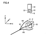
図4を参照して、第1干渉領域51に対する第1判定工程S61は、ロボットハンド22が電線W1を把持するときに他の電線W2、W3と干渉するか否かを判定する。
Referring to FIG. 4, in the first determination step S61 for the first interference region 51, it is determined whether or not the robot hand 22 interferes with the other electric wires W2 and W3 when holding the electric wire W1.
第1干渉領域51は、電線W1の把持位置Pを含み、所定の形状および所定の大きさを有する平面状の領域である。第1干渉領域は、その中心に把持位置Pを含むことが好ましい。第1干渉領域の形状は特に限定されないが、好ましくは、多角形、円または楕円とする。第1干渉領域が多角形の場合は、好ましくは4角形、より好ましくは正方形である。計算の負荷が軽くなり、高速な判定が可能となるからである。第1干渉領域が多角形の場合、線状物の三次元形状を表す座標系(以下、単に「座標系」という)のいずれか2本の軸がなす平面に平行な辺を有する正方形を第1干渉領域とするのが特に好ましい。
The first interference area 51 is a planar area including the gripping position P of the electric wire W1 and having a predetermined shape and a predetermined size. The first interference region preferably includes the grip position P at the center thereof. The shape of the first interference region is not particularly limited, but is preferably a polygon, a circle, or an ellipse. When the first interference region is a polygon, it is preferably a quadrangle, more preferably a square. This is because the calculation load is reduced and high-speed determination is possible. When the first interference region is a polygon, a square having sides parallel to a plane formed by any two axes of a coordinate system (hereinafter simply referred to as a “coordinate system”) representing the three-dimensional shape of the linear object is One interference region is particularly preferable.
後述する第1拡張干渉領域をより小さくして第1予備判定の効率を向上できるからである。第1干渉領域が多角形でない場合は、好ましくは円である。同じく、計算の負荷が軽くなり、高速な判定が可能となるからである。
This is because the efficiency of the first preliminary determination can be improved by reducing the first extended interference region described later. If the first interference area is not a polygon, it is preferably a circle. Similarly, the calculation load is reduced and high-speed determination is possible.
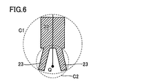
第1干渉領域51の大きさは、大きすぎると実際には干渉しないのに干渉すると誤判定する確率が増大する。図6を参照して、ロボットハンド22の最大断面に外接する最小の円を円C1とすると、第1干渉領域は、好ましくは、円C1の2.0倍の直径を有する円に内包される大きさであり、より好ましくは、円C1と同じ大きさの円に内包される大きさである。
If the size of the first interference area 51 is too large, the probability of misjudgment that interference does not actually occur increases. Referring to FIG. 6, when the smallest circle circumscribing the largest cross section of the robot hand 22 is defined as a circle C1, the first interference region is preferably included in a circle having a diameter 2.0 times that of the circle C1. More preferably, the size is contained in a circle having the same size as the circle C1.
一方、第1干渉領域が小さすぎると、実施には干渉するのに干渉しないと誤判定する確率が増大する。図6を参照して、ロボットハンド22が線状物を把持するために動作させる把持部23の最大断面に外接する最小の円を円C2とすると、第1干渉領域は、好ましくは、円C2(特願2017―221045号参照)と同じ大きさの円を内包できる大きさである。
On the other hand, if the first interference area is too small, the probability of misjudging that it does not interfere increases although it interferes with implementation. Referring to FIG. 6, when the minimum circle circumscribing the maximum cross section of the grip portion 23 that is operated by the robot hand 22 to grip the linear object is a circle C2, the first interference region is preferably a circle C2. It is a size that can contain a circle of the same size as that of Japanese Patent Application No. 2017-221405.
第1干渉領域51は、好ましくは、電線W1と直交する。第1干渉領域が注目線状物と直交するとは、把持位置Pにおいて注目線状物が伸びる方向が第1干渉領域と直角をなすことをいう。第1干渉領域を含む平面の方程式が容易に求められるからである。また、ロボットハンド22で線状物を把持する場合、線状物を真横から、つまり線状物と直角の方向から把持することが多いからである。注目線状物と直交する第1干渉領域内に他の線状物が存在する場合には、ロボットハンド22が注目線状物を真横から把持しない場合であっても、ロボットハンド22が当該他の線状物と干渉する蓋然性が高いからである。
The first interference region 51 is preferably orthogonal to the electric wire W1. That the first interference region is orthogonal to the target linear object means that the direction in which the target linear object extends at the gripping position P is perpendicular to the first interference region. This is because a plane equation including the first interference region can be easily obtained. In addition, when a linear object is gripped by the robot hand 22, the linear object is often gripped from the side, that is, from a direction perpendicular to the linear object. If there is another linear object in the first interference region orthogonal to the target linear object, even if the robot hand 22 does not grip the target linear object from the side, the robot hand 22 This is because there is a high probability of interference with the linear object.
図7を参照して、第1判定工程S61は、対象とする他の電線W2上の線分Lと第1干渉領域51との交差判定によって行なうことができる。線分Lは、電線W2の三次元形状を表す点群のうち隣り合う2点S、T間の線分とすることができる。線分Lが第1干渉領域と交差するなら、線分L上のどこかの点が第1干渉領域に含まれる。交差判定は公知の方法で行なうことができる。たとえば、第1干渉領域51を含む平面Uの法線ベクトルNと、把持位置Pから線分Lの両端S、TへのベクトルPSおよびPTとの内積を取り、2つの内積の符号が異なる場合は線分Lは平面Uと交差する。線分Lと平面Uが交差する場合は、その交点が第1干渉領域51内にあるか否かを判定すればよい。
Referring to FIG. 7, the first determination step S <b> 61 can be performed by determining the intersection of the line segment L on the other target electric wire W <b> 2 and the first interference region 51. The line segment L can be a line segment between two adjacent points S and T in the point group representing the three-dimensional shape of the electric wire W2. If the line segment L intersects the first interference area, some point on the line segment L is included in the first interference area. The intersection determination can be performed by a known method. For example, when the inner product of the normal vector N of the plane U including the first interference region 51 and the vectors PS and PT from the gripping position P to both ends S and T of the line segment L is taken, the signs of the two inner products are different The line segment L intersects the plane U. When the line segment L and the plane U intersect, it may be determined whether or not the intersection is in the first interference region 51.
図4を参照して、第1拡張干渉領域52に対する第1予備判定工程S62は、第1判定に先だって実施され、ロボットハンド22と他の電線W2、W3が干渉しない場合を、より高速な計算で発見するために行なう。
Referring to FIG. 4, the first preliminary determination step S62 for the first extended interference region 52 is performed prior to the first determination, and faster calculation is performed when the robot hand 22 does not interfere with the other electric wires W2, W3. To find out.
第1拡張干渉領域52は第1干渉領域51を内包する空間領域である。第1拡張干渉領域の形状や大きさは特に限定されないが、好ましくは、第1干渉領域を内包し、すべての辺が座標系のいずれかの軸に平行な6面体のうち最小のものを第1拡張干渉領域として設定する。座標系が直交座標系の場合は、この6面体は直方体である。これにより、座標の大小比較を行なうだけで、第1予備判定が実施できる。
The first extended interference region 52 is a spatial region that includes the first interference region 51. The shape and size of the first extended interference region are not particularly limited, but preferably the smallest one of the hexahedrons including the first interference region and having all sides parallel to any axis of the coordinate system is the first. Set as one extended interference area. When the coordinate system is an orthogonal coordinate system, the hexahedron is a rectangular parallelepiped. Thus, the first preliminary determination can be performed only by comparing the coordinates.
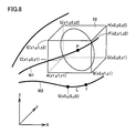
具体的には、図8を参照して、第1拡張干渉領域52の8つの頂点A~Hの座標を図8のとおりとし、線分Lの一方の端点Sの座標を(xS,yS,zS)とすると、x1≦xS≦x2、かつ、y1≦yS≦y2、かつ、z1≦zS≦z2、であれば点Sは第1拡張干渉領域内にあり、そうでなければ点Sは第1拡張干渉領域外にある。
Specifically, referring to FIG. 8, the coordinates of the eight vertices A to H of the first extended interference region 52 are as shown in FIG. 8, and the coordinates of one end point S of the line segment L are (xS, yS, zS), if x1 ≦ xS ≦ x2, y1 ≦ yS ≦ y2, and z1 ≦ zS ≦ z2, the point S is in the first extended interference region; otherwise, the point S is 1 Outside the extended interference area.
第1拡張干渉領域52が第1干渉領域51を内包するので、第1予備判定によってハンドと他の線状物が干渉しないとの結果が得られた場合は、第1判定を省略できる。
Since the first extended interference region 52 includes the first interference region 51, the first determination can be omitted if the result of the first preliminary determination indicates that the hand and other linear objects do not interfere with each other.
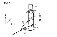
図5を参照して、第2干渉領域53に対する第2判定工程(S63)は、ロボットハンド22が電線W1の把持位置Pまで移動する経路で、他の電線W2、電線W3と干渉するか否かを判定する。
Referring to FIG. 5, in the second determination step (S63) for the second interference region 53, whether or not the robot hand 22 interferes with the other electric wires W2 and W3 on the path along which the robot hand 22 moves to the gripping position P of the electric wires W1. Determine whether.
第2干渉領域53は、電線W1の把持位置Pとロボットハンド22の待機位置Qとを結ぶ線分PQを含み、線分PQの両側に広がり所定の幅を有する平面状の領域である。第2干渉領域は、その幅方向の中心に線分PQを含むことが好ましい。第2干渉領域の形状は、特に限定されないが、好ましくは長方形または平行四辺形であり、より好ましくは、線分PQを線対称の対称軸とする長方形である。計算の負荷を軽くして、より高速に判定するためである。
The second interference region 53 is a planar region that includes a line segment PQ that connects the gripping position P of the electric wire W1 and the standby position Q of the robot hand 22, and has a predetermined width extending on both sides of the line segment PQ. The second interference region preferably includes a line segment PQ at the center in the width direction. The shape of the second interference region is not particularly limited, but is preferably a rectangle or a parallelogram, and more preferably a rectangle having a line segment PQ as an axis of symmetry of line symmetry. This is because the calculation load is reduced and the determination is made at a higher speed.
第2干渉領域53の幅は、広すぎると実際には干渉しないのに干渉すると誤判定する確率が増大する。第2干渉領域の幅は、好ましくは、図6の円C1の直径以下である。一方、第2干渉領域の幅が狭すぎると、実施には干渉するのに干渉しないと誤判定する確率が(特願2017―221045号参照)増大する。第2干渉領域の幅は、好ましくは、図6の円C2の直径以上である。
If the width of the second interference region 53 is too wide, the probability of misjudgment that interference does not actually occur increases. The width of the second interference region is preferably equal to or smaller than the diameter of the circle C1 in FIG. On the other hand, if the width of the second interference region is too narrow, the probability of misjudgment that it interferes with the implementation but does not interfere increases (see Japanese Patent Application No. 2017-221405). The width of the second interference region is preferably equal to or larger than the diameter of the circle C2 in FIG.
第2干渉領域53は、好ましくは、電線W1との交角が最大となるように設定される。ロボットハンド22が電線W1に接近する際に、把持部23、23がそのような平面内を進むことが多いからである。
The second interference region 53 is preferably set so that the intersection angle with the electric wire W1 is maximized. This is because, when the robot hand 22 approaches the electric wire W1, the gripping portions 23 and 23 often travel in such a plane.
第2判定工程S63は、第1判定工程S61と同様に、対象とする他の電線W2上の線分Lと第2干渉領域53との交差判定によって行なうことができる。
2nd determination process S63 can be performed by the intersection determination of the line segment L on the other electric wire W2 made into object, and the 2nd interference area | region 53 similarly to 1st determination process S61.
第2拡張干渉領域54に対する第2予備判定工程(S64)は、第2判定に先だって実施され、ロボットハンド22と他の電線W2、電線W3が干渉しない場合を、より高速な計算で発見するために行なう。
The second preliminary determination step (S64) for the second extended interference area 54 is performed prior to the second determination, and the case where the robot hand 22 does not interfere with the other electric wires W2 and W3 is found by faster calculation. To do.
第2拡張干渉領域54は第2干渉領域53を内包する空間領域である。第2拡張干渉領域の形状や大きさは特に限定されないが、好ましくは、第2干渉領域を内包し、すべての辺が座標系のいずれかの軸に平行な6面体のうち最小のものを第2拡張干渉領域として設定する。座標系が直交座標系の場合は、この6面体は直方体である。これにより、座標の大小比較を行なうだけで、第2予備判定が実施できる。
The second extended interference area 54 is a spatial area that includes the second interference area 53. The shape and size of the second extended interference region are not particularly limited, but preferably the smallest one of the hexahedrons including the second interference region and having all sides parallel to any axis of the coordinate system is the second. 2 Set as an extended interference area. When the coordinate system is an orthogonal coordinate system, the hexahedron is a rectangular parallelepiped. Thereby, the second preliminary determination can be performed only by comparing the size of the coordinates.
第2拡張干渉領域54が第2干渉領域53を内包するので、第2予備判定によってハンドと他の線状物が干渉しないとの結果が得られた場合は、第2判定を省略できる。
Since the second extended interference region 54 includes the second interference region 53, the second determination can be omitted when the second preliminary determination shows that the hand and other linear objects do not interfere with each other.
判定の対象とする線分Lを電線W2の長さ方向にずらしながら上記判定工程S61~S64を繰り返して、他の電線W2との干渉判定が完了したら、次の他の電線W3について同じ処理を行なう。
The above determination steps S61 to S64 are repeated while shifting the line segment L to be determined in the length direction of the electric wire W2, and when the interference determination with the other electric wire W2 is completed, the same processing is performed for the next other electric wire W3. Do.
すべての他の電線W2、W3が干渉領域51~54に含まれないと判定された場合は、制御装置32は電線W1の把持位置をロボットハンド22で把持する際に他の線状物の干渉がないと判定する。その後、電線W1を目標線状物として、その把持位置をロボット20に通知する。
When it is determined that all the other electric wires W2 and W3 are not included in the interference areas 51 to 54, the control device 32 interferes with other linear objects when the robot hand 22 holds the holding position of the electric wire W1. Judge that there is no. Then, the electric wire W1 is set as the target linear object, and the grip position is notified to the robot 20.
いずれかの第1判定または第2判定で線分Lが第1干渉領域または第2干渉領域に含まれると判定された場合は、制御装置32は電線W1の把持位置をロボットハンド22で把持する際に他の線状物の干渉があると判定する。以後の判定工程を省略して工程S22に戻り、注目線状物を変えて同じ処理を繰り返す。制御装置32が自律的に次の注目線状物を選択する場合は、たとえば、先に三次元カメラ31から取得した電線W1~W3の三次元形状に基づいて、次に高い位置にある線状物を注目線状物として選択することができる。
When it is determined by any of the first determination or the second determination that the line segment L is included in the first interference region or the second interference region, the control device 32 grips the gripping position of the electric wire W1 with the robot hand 22. It is determined that there is interference from other linear objects. The subsequent determination process is omitted, and the process returns to step S22, and the same processing is repeated while changing the target linear object. When the control device 32 autonomously selects the next linear object of interest, for example, based on the three-dimensional shape of the electric wires W1 to W3 previously obtained from the three-dimensional camera 31, the linear object at the next higher position is used. An object can be selected as a noticeable linear object.
何れの線状物に注目しても他の線状物と「干渉あり」と判定された場合は、線状物全体を回転させて向きを変えたり、線状物を振ったり振動させたりして線状物同士の位置関係を変化させてから、再度各工程を実施してもよい。各注目線状物の把持位置から最も近い他の線状物までの距離を干渉距離として計算しておき、干渉距離の長い線状物から把持するようにしてもよい。これにより、把持が成功しやすい順番で把持動作を実行するようロボットに指示することができる。干渉距離は、干渉判定における第1干渉領域または第2干渉領域と他の線状物との交点から把持位置までの距離を用いることで簡易に計算することができる。
If it is determined that there is interference with any other linear object regardless of which linear object, the entire linear object is rotated to change its orientation, or the linear object is shaken or vibrated. Then, each step may be performed again after changing the positional relationship between the linear objects. The distance from the gripping position of each target linear object to the nearest other linear object may be calculated as the interference distance, and the linear object having a long interference distance may be gripped. As a result, it is possible to instruct the robot to execute the gripping operation in the order in which gripping is likely to succeed. The interference distance can be easily calculated by using the distance from the intersection between the first interference region or the second interference region and another linear object in the interference determination to the gripping position.
以上のとおり、本関連技術の線状物把持方法によれば、線状物と他の線状物が干渉するか否かの判定結果に基づいて把持動作を実行するので、複数の線状物から1本の線状物を(特願2017―221045号参照)選んでロボットハンド22で把持することが可能となる。
As described above, according to the linear object gripping method of the related technology, since the gripping operation is executed based on the determination result of whether or not the linear object and other linear objects interfere, a plurality of linear objects Thus, it is possible to select one linear object (see Japanese Patent Application No. 2017-221405) and grip it with the robot hand 22.
ロボットハンド22の他の線状物との干渉の有無は、ロボットハンド22側のCADデータと線状物の三次元形状データを用いて、多面体との交差の有無を計算することによって実施してもよい。しかしこの方法は判定の正確さにおいて優れるが、時間のかかる処理である。
The presence or absence of interference with other linear objects of the robot hand 22 is implemented by calculating the presence or absence of intersection with the polyhedron using the CAD data on the robot hand 22 side and the three-dimensional shape data of the linear object. Also good. However, this method is excellent in accuracy of determination, but is a time-consuming process.
この関連技術では、注目線状物以外の線状物が第1干渉領域内に存在するか否かを、平面状の第1干渉領域と線状物との交差判定によって判定できるので、計算量が少なく、干渉の有無を高速に判定できる。第1干渉領域内に注目線状物以外の線状物が存在しない場合は、ロボットハンド22が他の線状物と干渉しないで注目線状物を把持できる蓋然性が高い。第2干渉領域についても同様である。
In this related technique, whether or not a linear object other than the target linear object exists in the first interference region can be determined by the intersection determination between the planar first interference region and the linear object. And the presence or absence of interference can be determined at high speed. When there is no linear object other than the target linear object in the first interference region, there is a high probability that the robot hand 22 can grip the target linear object without interfering with other linear objects. The same applies to the second interference region.
各判定工程を実施する順番は、第1予備判定を第1判定に先立って行ない、第2予備判定を第2判定に先立って行なう以外は、特に限定されない。上記実施形態では、第2判定工程を先に、第1判定工程を後で実施したが、この順番を逆にしてもよい。上記関連技術では、線分Lを線状物の長さ方向にずらしながら、1つの線分毎にすべての判定工程を実施したが、ある線状物について一つの判定工程(たとえば第2予備判定工程)を終えてから、改めて同じ線状物について他の判定工程(たとえば第2判定工程)を実施してもよい。
The order of performing each determination step is not particularly limited, except that the first preliminary determination is performed prior to the first determination and the second preliminary determination is performed prior to the second determination. In the said embodiment, although the 1st determination process was implemented after the 2nd determination process first, you may reverse this order. In the related technology, all determination processes are performed for each line segment while shifting the line segment L in the length direction of the linear object. However, one determination process (for example, the second preliminary determination) is performed for a certain linear object. After completing the step, another determination step (for example, a second determination step) may be performed on the same linear object.
上記関連技術では、ロボットハンド22の待機位置取得(S24)に先立って注目線状物を選択したが(S22)、先にロボットハンド22の待機位置を取得し、その待機位置に基づいて注目線状物を選択してもよい。その場合は、注目線状物として最も待機位置側にある線状物を選択できる。最も待機位置側にある線状物として、待機位置の座標と当該線状物の把持位置の座標との距離が最も短い線状物を選択してもよい。これにより、把持する際に他の線状物と干渉する可能性の低い線状物を優先的に選択できる点で好ましい。
In the related technology, the attention linear object is selected prior to the acquisition of the standby position of the robot hand 22 (S24) (S22), but the standby position of the robot hand 22 is acquired first, and the attention line is based on the standby position. A shape may be selected. In this case, the linear object that is closest to the standby position can be selected as the target linear object. As the linear object closest to the standby position, a linear object having the shortest distance between the coordinates of the standby position and the coordinates of the gripping position of the linear object may be selected. This is preferable in that a linear object that is unlikely to interfere with other linear objects can be preferentially selected when gripped.
ロボットハンド22が線状物を把持する際の姿勢(把持姿勢)は、把持部と線状物が略直角をなすように把持することが好ましい。把持部に対して把持位置から先端側の線状物の向きが略垂直であれば、把持した後に加工機等に挿入する際もロボットの制御が容易になるからである。好ましくは、待機位置において、把持した際に把持部と線状物とが直角をなす向きになるように、ロボットハンド22の姿勢を調整する。その後、ロボットハンド22は、待機位置から把持位置に向かって第2干渉領域に沿って移動する。これにより、ロボットハンド22の姿勢、ロボットハンド22の移動方向、ならびに第1および第2干渉領域の平面の向きが一致するため、高精度な干渉判定が可能となる。
The posture (gripping posture) when the robot hand 22 grips the linear object is preferably gripped so that the grip portion and the linear object are substantially perpendicular. This is because if the orientation of the linear object from the gripping position to the gripping portion is substantially perpendicular to the gripping part, the robot can be easily controlled even when it is inserted into a processing machine after gripping. Preferably, at the standby position, the posture of the robot hand 22 is adjusted so that the gripping portion and the linear object are oriented at right angles when gripped. Thereafter, the robot hand 22 moves along the second interference region from the standby position toward the gripping position. Thereby, since the posture of the robot hand 22, the moving direction of the robot hand 22, and the orientation of the planes of the first and second interference areas coincide, it is possible to perform highly accurate interference determination.
本発明によって線状物を把持したロボットハンド22が当該線状物を種々の製造装置・加工装置まで搬送してもよい。たとえば、把持した電線の先端をロボットハンド22によって移動させ、被膜剥き加工機や端子圧着装置等に挿入してもよい。電線の先端をコネクタ等の各種部品に挿入しワイヤーハーネスを製造する工程に用いてもよい。
The robot hand 22 holding the linear object according to the present invention may convey the linear object to various manufacturing apparatuses and processing apparatuses. For example, the tip of the gripped electric wire may be moved by the robot hand 22 and inserted into a film peeling machine or a terminal crimping device. You may use for the process of inserting the front-end | tip of an electric wire into various components, such as a connector, and manufacturing a wire harness.
(実施の形態:線状物の先端移動方法、制御装置、および、三次元カメラ)
次に、上記のように説明した、ロボット20に設けられたロボットハンド22が当該線状物を種々の製造装置・加工装置まで搬送する場合について検討する。具体的には、制御装置32(図1参照)により、ロボット20に設けられたロボットハンド22による線状物W1の移動を制御する。制御装置32は、線状物W1の三次元形状を取得する三次元カメラ31から線状物W1の三次元形状を取得し、この三次元形状から線状物W1の先端の位置を取得し、線状物W1の先端W1sの位置に基づき、先端W1sを目標位置に移動させるための情報をロボットハンド22を有するロボット20に通知することを想定している。
(Embodiment: Method for moving tip of linear object, control device, and three-dimensional camera)
Next, the case where the robot hand 22 provided in the robot 20 described above conveys the linear object to various manufacturing apparatuses and processing apparatuses will be considered. Specifically, the movement of the linear object W1 by the robot hand 22 provided in the robot 20 is controlled by the control device 32 (see FIG. 1). The control device 32 acquires the three-dimensional shape of the linear object W1 from the three-dimensional camera 31 that acquires the three-dimensional shape of the linear object W1, acquires the position of the tip of the linear object W1 from the three-dimensional shape, It is assumed that information for moving the tip W1s to the target position is notified to the robot 20 having the robot hand 22 based on the position of the tip W1s of the linear object W1.
図1に示した全体システム10においては、ロボットハンド22を有するロボット20、三次元カメラ31、および、制御装置32を有する構成としている。この制御装置32は、ロボット20および三次元カメラ31から独立した制御装置、ロボット20が備える制御装置、および、三次元カメラ31が備える制御装置のいずれであってもよい。
1 is configured to include a robot 20 having a robot hand 22, a three-dimensional camera 31, and a control device 32. The control device 32 may be any of a control device independent of the robot 20 and the three-dimensional camera 31, a control device provided in the robot 20, and a control device provided in the three-dimensional camera 31.
上記したように、ロボットハンド22が線状物を把持する際の姿勢(把持姿勢)は、把持部と線状物が略直角をなすように把持することが好ましい。しかしながら、ある程度の柔軟性を有する線状物を用いた場合には、ロボットハンド22で把持した線状物の先端側が真っ直ぐに延びておらず、曲がっている場合が想定される。
As described above, the posture (gripping posture) when the robot hand 22 grips the linear object is preferably gripped so that the grip portion and the linear object are substantially perpendicular. However, when a linear object having a certain degree of flexibility is used, it is assumed that the tip side of the linear object gripped by the robot hand 22 does not extend straight but is bent.
このような場合に、ロボットハンド22側が、線状物の先端側の曲りを認識しないまま線状物を搬送した場合には、所定の目標位置に線状物の先端を搬送できない状況となる。
In such a case, when the robot hand 22 side transports the linear object without recognizing the bending of the front end side of the linear object, the leading end of the linear object cannot be transported to a predetermined target position.
そこで、制御装置32は、線状物の三次元形状から線状物の先端の向きを計測し、線状物の先端の向きを所定の向きに一致させて目標位置まで移動させるための情報をロボットハンドを有するロボットに通知するようにするとよい。
Therefore, the control device 32 measures the direction of the tip of the linear object from the three-dimensional shape of the linear object, and matches the direction of the tip of the linear object with a predetermined direction to move the information to the target position. The robot having the robot hand may be notified.
以下の実施の形態においては、線状物を把持したロボットハンド22による線状物を所定位置に搬送する場合の、線状物の先端曲り量計測方法について以下説明する。以下の説明では、所定位置への搬送の一例として、ターゲットTGに設けられた孔TGHに、線状物として電線W1の先端W1sを挿入させる場合について説明する。
In the following embodiment, a method for measuring the amount of bending of the tip of a linear object when the linear object is conveyed to a predetermined position by the robot hand 22 holding the linear object will be described below. In the following description, a case where the tip W1s of the electric wire W1 is inserted as a linear object into the hole TGH provided in the target TG will be described as an example of conveyance to a predetermined position.
ここで、線状物の直径は、三次元カメラで認識できる範囲であればよく、好ましくは0.01mm~10cmである。ターゲットTGに設けられた孔TGHは、線状物を挿入することができる大きさであればよく、好ましくは直径が0.01mm~15cm、孔深さは線状物の直径の2倍以上が好ましい。
Here, the diameter of the linear object may be in a range that can be recognized by a three-dimensional camera, and is preferably 0.01 mm to 10 cm. The hole TGH provided in the target TG has only to have a size capable of inserting a linear object, and preferably has a diameter of 0.01 mm to 15 cm and a hole depth of at least twice the diameter of the linear object. preferable.
図9を参照して、ロボットハンド22により電線W1を把持した状態を示している。さらに電線W1の先端W1sは、ロボットハンド22に対して略直角をなすように延びておらず曲がった状態となっている。
Referring to FIG. 9, a state in which the electric wire W1 is gripped by the robot hand 22 is shown. Furthermore, the tip W1s of the electric wire W1 is not extended so as to be substantially perpendicular to the robot hand 22, but is bent.
ロボットハンド22により把持された電線W1の先端W1sの位置を計測する。この時、ロボットハンド22に対して略直角に延びる方向をL1とした場合に、電線W1の先端W1sがL1に対してどれだけずれているかの先端曲り量を計測してもよい。先端W1sの位置の計測においては、上述した三次元カメラ31を用いて三次元形状を計測できる。これにより、先端W1sの位置やズレ量X1を知ることができる。
Measure the position of the tip W1s of the electric wire W1 gripped by the robot hand 22. At this time, when the direction extending substantially perpendicular to the robot hand 22 is L1, the tip bending amount of how much the tip W1s of the electric wire W1 is shifted from L1 may be measured. In the measurement of the position of the tip W1s, the three-dimensional shape can be measured using the three-dimensional camera 31 described above. As a result, the position of the tip W1s and the displacement amount X1 can be known.
さらに、電線W1の先端W1sから所定距離位置(図9中の距離D1)までの形状を測定し、平均ベクトルを求めることで、電線W1の先端の延びる向きを決定することができる。また、電線W1の先端W1sと、先端W1sから孔への挿入長さの位置とを結ぶベクトルを先端の向きとしてもよい。
Furthermore, the extending direction of the tip of the electric wire W1 can be determined by measuring the shape from the tip W1s of the electric wire W1 to a predetermined distance position (distance D1 in FIG. 9) and obtaining an average vector. Alternatively, the direction of the tip may be a vector connecting the tip W1s of the electric wire W1 and the position of the insertion length from the tip W1s to the hole.
これにより、ターゲットTGに設けられた孔TGHに先端W1sを挿入する際の適切な姿勢の向きが判定できる。電線W1の先端W1sから所定距離位置(図9中の距離D1)は、好ましくはターゲットTGに設けられた孔TGHの孔深さの0.3~10倍、より好ましくは、0.5~5倍である。先端からの曲り量を計測し、急峻に変化する点までをD1としてもよい。次に、電線W1の先端W1sの位置や先端曲り量の計測を終えると、その位置や先端曲り量をロボットハンド22の移動制御にフィードバックする。
Thereby, it is possible to determine the orientation of an appropriate posture when the tip W1s is inserted into the hole TGH provided in the target TG. The predetermined distance position (distance D1 in FIG. 9) from the tip W1s of the electric wire W1 is preferably 0.3 to 10 times the hole depth of the hole TGH provided in the target TG, more preferably 0.5 to 5 Is double. The amount of bending from the tip may be measured, and a point up to a sharp change may be set as D1. Next, when the measurement of the position of the tip W1s and the tip bending amount of the electric wire W1 is finished, the position and the tip bending amount are fed back to the movement control of the robot hand 22.
図9に示すように、先端W1sの位置や先端曲り量からフィードバック量を与えることで、先端W1sをターゲットTGに設けられた孔TGHに移動させることが可能である。この場合、孔TGHの孔深さが浅い場合には問題が生じることは少ない。しかし、孔TGHの孔深さが深い場合や孔TGHの直径が小さく電線W1の直径とあまり変わりない場合には、電線を孔に挿入できるような所定の向きに先端W1sの向きを一致させて移動させる必要がある。具体的には、孔TGHの中心軸TG-Aの延びる方向に沿って先端W1sを移動させる必要がある。
As shown in FIG. 9, the tip W1s can be moved to the hole TGH provided in the target TG by giving a feedback amount from the position of the tip W1s and the tip bending amount. In this case, when the hole depth of the hole TGH is shallow, there is little problem. However, when the hole TGH has a deep hole depth or when the hole TGH has a small diameter and does not differ much from the diameter of the electric wire W1, the direction of the tip W1s is made to coincide with a predetermined direction so that the electric wire can be inserted into the hole. Must be moved. Specifically, it is necessary to move the tip W1s along the direction in which the central axis TG-A of the hole TGH extends.
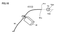
そこで、図10に示すように、孔TGHの中心軸TG-Aの延長線上に位置する手前位置P11を予め定めておき、手前位置P11に先端W1sを移動させるとともに、孔TGHの中心軸TG-Aの方向と、電線W1の先端の向きとを一致させる移動を行なう。
Therefore, as shown in FIG. 10, a near position P11 located on the extension line of the center axis TG-A of the hole TGH is determined in advance, the tip W1s is moved to the near position P11, and the center axis TG- of the hole TGH is set. Movement is performed so that the direction A matches the direction of the tip of the electric wire W1.
移動方法は、先端W1sを手前位置P11に移動させながら向きを一致させてもよいし、先端W1sを手前位置まで平行移動させてから、手前位置で向きを一致させるように電線W1を回転させてもよい。手前位置は、目標位置付近であることが好ましく、目標位置が孔である場合は、孔の中心軸の延びる線上であることが好ましい。目標位置が溝である場合は、溝の直上であることが好ましい。目標位置が端子台である場合は、端子をつなげる位置から端子をつなげる方向に延びる線上であることが好ましい。
The moving method may be to match the direction while moving the tip W1s to the near position P11, or after moving the tip W1s to the near position and then rotating the electric wire W1 to match the direction at the near position. Also good. The near position is preferably near the target position, and when the target position is a hole, it is preferably on a line extending the central axis of the hole. When the target position is a groove, it is preferable to be directly above the groove. When the target position is a terminal block, it is preferable that the target position is on a line extending in a direction in which the terminals are connected from a position where the terminals are connected.
その後、中心軸TG-Aの延びる線上に沿って先端W1sを移動させることにより、孔TGHの孔深さが深い場合や孔TGHの直径が小さい場合であっても、先端W1sを孔TGHの内部に挿通させることが可能となる。
Thereafter, by moving the tip W1s along the line extending the central axis TG-A, the tip W1s is moved into the hole TGH even when the hole TGH is deep or the hole TGH has a small diameter. It becomes possible to let it pass through.
なお、孔TGHに電線W1を挿入できたかどうかをセンサ等で判断し、挿入に失敗していた場合には、電線W1を手前位置P11に戻して、再度電線W1の先端W1s位置と向きを計測し、孔TGHの中心軸TG-Aの延びる方向と電線W1の先端の向きとを合わせて、先端W1sを孔TGHに移動させてもよい。
In addition, it is judged by a sensor or the like whether or not the electric wire W1 has been inserted into the hole TGH. If the insertion has failed, the electric wire W1 is returned to the front position P11 and the position and orientation of the tip W1s of the electric wire W1 are measured again. Then, the tip W1s may be moved to the hole TGH by matching the direction in which the central axis TG-A of the hole TGH extends and the direction of the tip of the electric wire W1.
具体的な、電線W1の電線先端曲り量計測方法について以下説明する。たとえば、ロボットハンド22から長さ100mmの電線W1が出た状態と仮定する。
A specific method for measuring the bending amount of the wire tip of the wire W1 will be described below. For example, it is assumed that an electric wire W1 having a length of 100 mm comes out from the robot hand 22.
[目標位置のティーチング]
事前に、ロボット座標系における目標位置の座標を登録する。ロボットハンド22に電線W1ではなく、100mmのまっすぐな棒B(図9参照)を把持させる。ロボットハンド22は、適当な位置をつかんでいるので、棒Bの突出長さは100±数mmである。この棒Bは、電線と同一直径にする。その後、上記の棒Bを三次元カメラでスキャンする。
[Teaching the target position]
The coordinates of the target position in the robot coordinate system are registered in advance. The robot hand 22 is caused to grip the 100 mm straight bar B (see FIG. 9) instead of the electric wire W1. Since the robot hand 22 holds an appropriate position, the protruding length of the bar B is 100 ± several mm. This bar B has the same diameter as the electric wire. Thereafter, the bar B is scanned with a three-dimensional camera.
次に、ロボットハンド22から棒Bの先端の相対座標が計算できる。これをたとえば、P1のように基準データとして保持する。
Next, the relative coordinates of the tip of the rod B can be calculated from the robot hand 22. This is held as reference data, for example, P1.
棒の先端を、電線W1を挿入したい孔位置まで移動させる。移動させた時の棒の先端位置が目標位置となる。目標位置は、孔の中に設定してもよいし、孔の入り口付近に設定してもよい。移動させた棒の先端のロボット座標系における座標を目標位置として登録する。これは、ロボットハンドの座標にP1を足すことで計算できる。この位置をP0と登録する。以上で目標位置のティーチングが終了する。
移動 Move the tip of the rod to the hole position where you want to insert the wire W1. The tip position of the rod when moved is the target position. The target position may be set in the hole or may be set near the entrance of the hole. The coordinates of the tip of the moved bar in the robot coordinate system are registered as the target position. This can be calculated by adding P1 to the coordinates of the robot hand. This position is registered as P0. This completes teaching of the target position.
[電線の移動]
ロボットハンド22に移動したい電線W1を把持させる。その後、電線W1を三次元カメラでスキャンする。
[Move wire]
The robot hand 22 grips the electric wire W1 to be moved. Thereafter, the electric wire W1 is scanned with a three-dimensional camera.
ロボットハンド22から電線W1の先端W1sまでの相対座標が計算できる。これをたとえば、P2とすると、P0―P2で計算されるベクトルを移動ベクトルとしてロボットに通知し、ロボットが電線を移動させる。
The relative coordinates from the robot hand 22 to the tip W1s of the electric wire W1 can be calculated. If this is P2, for example, the vector calculated in P0-P2 is notified to the robot as a movement vector, and the robot moves the electric wire.
これにより、先端W1sと孔TGHとの位置が合うこととなる。
[電線の移動+方向変更]
ここで、P2は先端座標であることから、これに先端方向(Rx,Ry,Rz)を同時に計算すれば、上記したように、孔TGHの中心軸TG-Aの延びる方向と、電線W1の先端の延びる方向とを一致させることが可能となる。先端W1sの移動方法は、上記したように予め定めた手前位置P11まで平行移動させ、手前位置P11で電線W1の先端の向きを孔TGHの中心軸TG-Aの方向に一致させるよう回転し、その後、中心軸TG-Aの延びる線上に沿って先端W1sを移動させてもよい。また、手前位置P11を定めずに、電線W1の先端の延びる方向を孔TGHの中心軸TG-Aの延びる方向に一致させるよう回転させながら、初期位置から孔TGHへ移動させてもよい。先端W1sが目標位置P0に到達する際、先端W1sの向きが所定の向きに一致するように、線状物W1の先端W1sを所定位置に移動させる移動方法であればよい。
Thereby, the position of the front-end | tip W1s and the hole TGH will correspond.
[Move wire + change direction]
Here, since P2 is the tip coordinate, if the tip direction (Rx, Ry, Rz) is calculated at the same time, as described above, the direction in which the central axis TG-A of the hole TGH extends and the wire W1 It is possible to match the direction in which the tip extends. As described above, the tip W1s is moved in parallel to a predetermined near position P11 as described above, and rotated so that the direction of the tip of the electric wire W1 coincides with the direction of the central axis TG-A of the hole TGH at the near position P11. Thereafter, the tip W1s may be moved along a line extending the central axis TG-A. Further, without defining the near position P11, the wire W1 may be moved from the initial position to the hole TGH while being rotated so that the extending direction of the tip of the electric wire W1 coincides with the extending direction of the central axis TG-A of the hole TGH. Any moving method that moves the tip W1s of the linear object W1 to a predetermined position so that the direction of the tip W1s matches a predetermined direction when the tip W1s reaches the target position P0 may be used.
線状物を所定位置へ搬送する一例として、ターゲットTGに設けられた孔TGHに、線状物として電線W1の先端W1sを挿入させる場合について説明したが、線状物および目標位置はこれに限定されない。目標位置が孔である具体例としては、電線の先端を検査する検査装置、電線の被膜を剥くワイヤーストリッパー、電線とコネクタを接続する加工機、電線の先端に圧着端子をかしめる加工装置などの所定位置が挙げられる。
As an example of conveying a linear object to a predetermined position, the case where the tip W1s of the electric wire W1 is inserted as a linear object into the hole TGH provided in the target TG has been described. However, the linear object and the target position are limited to this. Not. Specific examples where the target position is a hole include an inspection device that inspects the tip of the wire, a wire stripper that strips the coating of the wire, a processing machine that connects the wire and the connector, and a processing device that crimps a crimp terminal on the tip of the wire. A predetermined position is mentioned.
その他の実施例として、例えば、基板に配線をはんだ付けする場合、配線の向きや他の部品の位置に応じて、はんだの向きを制御する必要がある。この場合、線状物をはんだとして、目標位置をはんだ付けしたい基板の所定箇所または基板の所定箇所の直上付近として本発明を利用できる。
As another example, for example, when soldering a wiring to a substrate, it is necessary to control the direction of the solder according to the direction of the wiring and the position of other components. In this case, the present invention can be used as a solder where the linear object is a solder and the target position is a predetermined position of the substrate to be soldered or a position immediately above the predetermined position of the substrate.
また、端子付きの電線を端子台に移動させる場合には、端子を端子台につなげる向きに制約があるため、端子付き電線の向きを端子台につなげられる所定の向きに一致させるように移動させる必要がある。この場合、線状物は端子付きの電線、目標位置は端子台の所定箇所または所定箇所付近として本実施の形態を利用することができる。このように、目標位置は、孔に限定されず、所定の検査位置、加工作業位置、面や溝、またはこれらの直上付近の所定箇所でもよい。
Also, when moving the electric wire with terminal to the terminal block, there are restrictions on the direction in which the terminal is connected to the terminal block, so the direction of the electric wire with terminal is moved to match the predetermined direction connected to the terminal block. There is a need. In this case, the present embodiment can be used by assuming that the linear object is an electric wire with a terminal, and the target position is a predetermined position or a vicinity of the predetermined position of the terminal block. As described above, the target position is not limited to the hole, and may be a predetermined inspection position, a processing work position, a surface or a groove, or a predetermined location in the vicinity thereof.
今回開示された実施の形態はすべての点で例示であって制限的なものではないと考えられるべきである。本発明の範囲は上記した説明ではなくて請求の範囲によって示され、請求の範囲と均等の意味および範囲内でのすべての変更が含まれることが意図される。
The embodiment disclosed this time should be considered as illustrative in all points and not restrictive. The scope of the present invention is defined by the terms of the claims, rather than the description above, and is intended to include any modifications within the scope and meaning equivalent to the terms of the claims.