WO2019159550A1 - 旋回式作業機械 - Google Patents
旋回式作業機械 Download PDFInfo
- Publication number
- WO2019159550A1 WO2019159550A1 PCT/JP2018/048015 JP2018048015W WO2019159550A1 WO 2019159550 A1 WO2019159550 A1 WO 2019159550A1 JP 2018048015 W JP2018048015 W JP 2018048015W WO 2019159550 A1 WO2019159550 A1 WO 2019159550A1
- Authority
- WO
- WIPO (PCT)
- Prior art keywords
- turning
- capacity
- motor
- pressure
- swing
- Prior art date
Links
Images


Classifications
-
- E—FIXED CONSTRUCTIONS
- E02—HYDRAULIC ENGINEERING; FOUNDATIONS; SOIL SHIFTING
- E02F—DREDGING; SOIL-SHIFTING
- E02F9/00—Component parts of dredgers or soil-shifting machines, not restricted to one of the kinds covered by groups E02F3/00 - E02F7/00
- E02F9/08—Superstructures; Supports for superstructures
- E02F9/10—Supports for movable superstructures mounted on travelling or walking gears or on other superstructures
- E02F9/12—Slewing or traversing gears
- E02F9/121—Turntables, i.e. structure rotatable about 360°
- E02F9/128—Braking systems
-
- E—FIXED CONSTRUCTIONS
- E02—HYDRAULIC ENGINEERING; FOUNDATIONS; SOIL SHIFTING
- E02F—DREDGING; SOIL-SHIFTING
- E02F9/00—Component parts of dredgers or soil-shifting machines, not restricted to one of the kinds covered by groups E02F3/00 - E02F7/00
- E02F9/08—Superstructures; Supports for superstructures
- E02F9/10—Supports for movable superstructures mounted on travelling or walking gears or on other superstructures
- E02F9/12—Slewing or traversing gears
- E02F9/121—Turntables, i.e. structure rotatable about 360°
- E02F9/123—Drives or control devices specially adapted therefor
-
- E—FIXED CONSTRUCTIONS
- E02—HYDRAULIC ENGINEERING; FOUNDATIONS; SOIL SHIFTING
- E02F—DREDGING; SOIL-SHIFTING
- E02F9/00—Component parts of dredgers or soil-shifting machines, not restricted to one of the kinds covered by groups E02F3/00 - E02F7/00
- E02F9/20—Drives; Control devices
- E02F9/22—Hydraulic or pneumatic drives
- E02F9/2221—Control of flow rate; Load sensing arrangements
- E02F9/2232—Control of flow rate; Load sensing arrangements using one or more variable displacement pumps
- E02F9/2235—Control of flow rate; Load sensing arrangements using one or more variable displacement pumps including an electronic controller
-
- E—FIXED CONSTRUCTIONS
- E02—HYDRAULIC ENGINEERING; FOUNDATIONS; SOIL SHIFTING
- E02F—DREDGING; SOIL-SHIFTING
- E02F9/00—Component parts of dredgers or soil-shifting machines, not restricted to one of the kinds covered by groups E02F3/00 - E02F7/00
- E02F9/20—Drives; Control devices
- E02F9/22—Hydraulic or pneumatic drives
- E02F9/2278—Hydraulic circuits
- E02F9/2285—Pilot-operated systems
-
- E—FIXED CONSTRUCTIONS
- E02—HYDRAULIC ENGINEERING; FOUNDATIONS; SOIL SHIFTING
- E02F—DREDGING; SOIL-SHIFTING
- E02F9/00—Component parts of dredgers or soil-shifting machines, not restricted to one of the kinds covered by groups E02F3/00 - E02F7/00
- E02F9/20—Drives; Control devices
- E02F9/22—Hydraulic or pneumatic drives
- E02F9/2278—Hydraulic circuits
- E02F9/2296—Systems with a variable displacement pump
-
- F—MECHANICAL ENGINEERING; LIGHTING; HEATING; WEAPONS; BLASTING
- F15—FLUID-PRESSURE ACTUATORS; HYDRAULICS OR PNEUMATICS IN GENERAL
- F15B—SYSTEMS ACTING BY MEANS OF FLUIDS IN GENERAL; FLUID-PRESSURE ACTUATORS, e.g. SERVOMOTORS; DETAILS OF FLUID-PRESSURE SYSTEMS, NOT OTHERWISE PROVIDED FOR
- F15B11/00—Servomotor systems without provision for follow-up action; Circuits therefor
- F15B11/02—Systems essentially incorporating special features for controlling the speed or actuating force of an output member
- F15B11/04—Systems essentially incorporating special features for controlling the speed or actuating force of an output member for controlling the speed
- F15B11/046—Systems essentially incorporating special features for controlling the speed or actuating force of an output member for controlling the speed depending on the position of the working member
- F15B11/048—Systems essentially incorporating special features for controlling the speed or actuating force of an output member for controlling the speed depending on the position of the working member with deceleration control
-
- F—MECHANICAL ENGINEERING; LIGHTING; HEATING; WEAPONS; BLASTING
- F15—FLUID-PRESSURE ACTUATORS; HYDRAULICS OR PNEUMATICS IN GENERAL
- F15B—SYSTEMS ACTING BY MEANS OF FLUIDS IN GENERAL; FLUID-PRESSURE ACTUATORS, e.g. SERVOMOTORS; DETAILS OF FLUID-PRESSURE SYSTEMS, NOT OTHERWISE PROVIDED FOR
- F15B11/00—Servomotor systems without provision for follow-up action; Circuits therefor
- F15B11/16—Servomotor systems without provision for follow-up action; Circuits therefor with two or more servomotors
-
- F—MECHANICAL ENGINEERING; LIGHTING; HEATING; WEAPONS; BLASTING
- F15—FLUID-PRESSURE ACTUATORS; HYDRAULICS OR PNEUMATICS IN GENERAL
- F15B—SYSTEMS ACTING BY MEANS OF FLUIDS IN GENERAL; FLUID-PRESSURE ACTUATORS, e.g. SERVOMOTORS; DETAILS OF FLUID-PRESSURE SYSTEMS, NOT OTHERWISE PROVIDED FOR
- F15B2211/00—Circuits for servomotor systems
- F15B2211/20—Fluid pressure source, e.g. accumulator or variable axial piston pump
- F15B2211/205—Systems with pumps
- F15B2211/20576—Systems with pumps with multiple pumps
-
- F—MECHANICAL ENGINEERING; LIGHTING; HEATING; WEAPONS; BLASTING
- F15—FLUID-PRESSURE ACTUATORS; HYDRAULICS OR PNEUMATICS IN GENERAL
- F15B—SYSTEMS ACTING BY MEANS OF FLUIDS IN GENERAL; FLUID-PRESSURE ACTUATORS, e.g. SERVOMOTORS; DETAILS OF FLUID-PRESSURE SYSTEMS, NOT OTHERWISE PROVIDED FOR
- F15B2211/00—Circuits for servomotor systems
- F15B2211/60—Circuit components or control therefor
- F15B2211/63—Electronic controllers
- F15B2211/6303—Electronic controllers using input signals
- F15B2211/6306—Electronic controllers using input signals representing a pressure
- F15B2211/6309—Electronic controllers using input signals representing a pressure the pressure being a pressure source supply pressure
-
- F—MECHANICAL ENGINEERING; LIGHTING; HEATING; WEAPONS; BLASTING
- F15—FLUID-PRESSURE ACTUATORS; HYDRAULICS OR PNEUMATICS IN GENERAL
- F15B—SYSTEMS ACTING BY MEANS OF FLUIDS IN GENERAL; FLUID-PRESSURE ACTUATORS, e.g. SERVOMOTORS; DETAILS OF FLUID-PRESSURE SYSTEMS, NOT OTHERWISE PROVIDED FOR
- F15B2211/00—Circuits for servomotor systems
- F15B2211/60—Circuit components or control therefor
- F15B2211/63—Electronic controllers
- F15B2211/6303—Electronic controllers using input signals
- F15B2211/6306—Electronic controllers using input signals representing a pressure
- F15B2211/6313—Electronic controllers using input signals representing a pressure the pressure being a load pressure
-
- F—MECHANICAL ENGINEERING; LIGHTING; HEATING; WEAPONS; BLASTING
- F15—FLUID-PRESSURE ACTUATORS; HYDRAULICS OR PNEUMATICS IN GENERAL
- F15B—SYSTEMS ACTING BY MEANS OF FLUIDS IN GENERAL; FLUID-PRESSURE ACTUATORS, e.g. SERVOMOTORS; DETAILS OF FLUID-PRESSURE SYSTEMS, NOT OTHERWISE PROVIDED FOR
- F15B2211/00—Circuits for servomotor systems
- F15B2211/60—Circuit components or control therefor
- F15B2211/63—Electronic controllers
- F15B2211/6303—Electronic controllers using input signals
- F15B2211/6336—Electronic controllers using input signals representing a state of the output member, e.g. position, speed or acceleration
-
- F—MECHANICAL ENGINEERING; LIGHTING; HEATING; WEAPONS; BLASTING
- F15—FLUID-PRESSURE ACTUATORS; HYDRAULICS OR PNEUMATICS IN GENERAL
- F15B—SYSTEMS ACTING BY MEANS OF FLUIDS IN GENERAL; FLUID-PRESSURE ACTUATORS, e.g. SERVOMOTORS; DETAILS OF FLUID-PRESSURE SYSTEMS, NOT OTHERWISE PROVIDED FOR
- F15B2211/00—Circuits for servomotor systems
- F15B2211/60—Circuit components or control therefor
- F15B2211/665—Methods of control using electronic components
-
- F—MECHANICAL ENGINEERING; LIGHTING; HEATING; WEAPONS; BLASTING
- F15—FLUID-PRESSURE ACTUATORS; HYDRAULICS OR PNEUMATICS IN GENERAL
- F15B—SYSTEMS ACTING BY MEANS OF FLUIDS IN GENERAL; FLUID-PRESSURE ACTUATORS, e.g. SERVOMOTORS; DETAILS OF FLUID-PRESSURE SYSTEMS, NOT OTHERWISE PROVIDED FOR
- F15B2211/00—Circuits for servomotor systems
- F15B2211/70—Output members, e.g. hydraulic motors or cylinders or control therefor
- F15B2211/705—Output members, e.g. hydraulic motors or cylinders or control therefor characterised by the type of output members or actuators
- F15B2211/7058—Rotary output members
-
- F—MECHANICAL ENGINEERING; LIGHTING; HEATING; WEAPONS; BLASTING
- F15—FLUID-PRESSURE ACTUATORS; HYDRAULICS OR PNEUMATICS IN GENERAL
- F15B—SYSTEMS ACTING BY MEANS OF FLUIDS IN GENERAL; FLUID-PRESSURE ACTUATORS, e.g. SERVOMOTORS; DETAILS OF FLUID-PRESSURE SYSTEMS, NOT OTHERWISE PROVIDED FOR
- F15B2211/00—Circuits for servomotor systems
- F15B2211/70—Output members, e.g. hydraulic motors or cylinders or control therefor
- F15B2211/71—Multiple output members, e.g. multiple hydraulic motors or cylinders
- F15B2211/7135—Combinations of output members of different types, e.g. single-acting cylinders with rotary motors
-
- F—MECHANICAL ENGINEERING; LIGHTING; HEATING; WEAPONS; BLASTING
- F15—FLUID-PRESSURE ACTUATORS; HYDRAULICS OR PNEUMATICS IN GENERAL
- F15B—SYSTEMS ACTING BY MEANS OF FLUIDS IN GENERAL; FLUID-PRESSURE ACTUATORS, e.g. SERVOMOTORS; DETAILS OF FLUID-PRESSURE SYSTEMS, NOT OTHERWISE PROVIDED FOR
- F15B2211/00—Circuits for servomotor systems
- F15B2211/70—Output members, e.g. hydraulic motors or cylinders or control therefor
- F15B2211/715—Output members, e.g. hydraulic motors or cylinders or control therefor having braking means
-
- F—MECHANICAL ENGINEERING; LIGHTING; HEATING; WEAPONS; BLASTING
- F15—FLUID-PRESSURE ACTUATORS; HYDRAULICS OR PNEUMATICS IN GENERAL
- F15B—SYSTEMS ACTING BY MEANS OF FLUIDS IN GENERAL; FLUID-PRESSURE ACTUATORS, e.g. SERVOMOTORS; DETAILS OF FLUID-PRESSURE SYSTEMS, NOT OTHERWISE PROVIDED FOR
- F15B2211/00—Circuits for servomotor systems
- F15B2211/70—Output members, e.g. hydraulic motors or cylinders or control therefor
- F15B2211/755—Control of acceleration or deceleration of the output member
-
- F—MECHANICAL ENGINEERING; LIGHTING; HEATING; WEAPONS; BLASTING
- F15—FLUID-PRESSURE ACTUATORS; HYDRAULICS OR PNEUMATICS IN GENERAL
- F15B—SYSTEMS ACTING BY MEANS OF FLUIDS IN GENERAL; FLUID-PRESSURE ACTUATORS, e.g. SERVOMOTORS; DETAILS OF FLUID-PRESSURE SYSTEMS, NOT OTHERWISE PROVIDED FOR
- F15B2211/00—Circuits for servomotor systems
- F15B2211/70—Output members, e.g. hydraulic motors or cylinders or control therefor
- F15B2211/76—Control of force or torque of the output member
- F15B2211/763—Control of torque of the output member by means of a variable capacity motor, i.e. by a secondary control on the motor
-
- F—MECHANICAL ENGINEERING; LIGHTING; HEATING; WEAPONS; BLASTING
- F15—FLUID-PRESSURE ACTUATORS; HYDRAULICS OR PNEUMATICS IN GENERAL
- F15B—SYSTEMS ACTING BY MEANS OF FLUIDS IN GENERAL; FLUID-PRESSURE ACTUATORS, e.g. SERVOMOTORS; DETAILS OF FLUID-PRESSURE SYSTEMS, NOT OTHERWISE PROVIDED FOR
- F15B2211/00—Circuits for servomotor systems
- F15B2211/70—Output members, e.g. hydraulic motors or cylinders or control therefor
- F15B2211/78—Control of multiple output members
-
- F—MECHANICAL ENGINEERING; LIGHTING; HEATING; WEAPONS; BLASTING
- F15—FLUID-PRESSURE ACTUATORS; HYDRAULICS OR PNEUMATICS IN GENERAL
- F15B—SYSTEMS ACTING BY MEANS OF FLUIDS IN GENERAL; FLUID-PRESSURE ACTUATORS, e.g. SERVOMOTORS; DETAILS OF FLUID-PRESSURE SYSTEMS, NOT OTHERWISE PROVIDED FOR
- F15B2211/00—Circuits for servomotor systems
- F15B2211/80—Other types of control related to particular problems or conditions
- F15B2211/85—Control during special operating conditions
- F15B2211/853—Control during special operating conditions during stopping
Definitions
- the present invention relates to a swivel work machine such as a hydraulic excavator.
- the swivel work machine is generally a lower traveling body, an upper revolving body that is turnably mounted on the lower traveling body, an attachment that is attached to the upper revolving body, and a hydraulic motor that revolves the upper revolving body.
- the turning control valve opens and closes according to the operation of the turning operation lever by the operator, and changes the flow rate of the hydraulic oil supplied to the turning motor among the hydraulic oil discharged from the hydraulic pump.
- the hydraulic oil discharged from the hydraulic pump is often used not only for the swing motor but also for other hydraulic actuators (for example, boom cylinders).
- the other hydraulic actuator is connected to the hydraulic pump via a dedicated control valve different from the turning control valve. That is, the hydraulic pump is used both for supplying hydraulic oil to the swing motor and for supplying hydraulic oil to the other hydraulic actuators.
- Patent Document 1 discloses a hydraulic device that supplies hydraulic oil from a single hydraulic pump to a boom cylinder and a turning hydraulic motor to drive them.
- the operation of the turning hydraulic motor and other actuators is controlled by adjusting the tilting capacity of the turning motor.
- the braking characteristics of the swing motor at the time of the swing deceleration change according to the motor capacity, so that stable deceleration operation cannot be performed.
- it is desired that the braking characteristics during deceleration are stable for safety.
- An object of the present invention is to provide a swivel work machine capable of obtaining a stable brake characteristic when the turning of the upper swing body is decelerated while the motor capacity is set to a capacity suitable for the complex operation during the complex operation. There is.
- a swivel work machine comprising a base, an upper swivel mounted so as to be able to swivel on the base, an attachment mounted on the upper swivel, and hydraulic oil.
- a revolving hydraulic pump comprising a discharge hydraulic pump and a variable displacement hydraulic motor, which operates to revolve the upper revolving body upon receiving the supply of the hydraulic oil discharged from the hydraulic pump, and is discharged from the hydraulic pump
- An actuator that operates to operate the attachment in response to supply of the hydraulic oil, a brake circuit that brakes the swing motor to decelerate the swing of the upper swing body, and the swing of the upper swing body decelerates
- a turning state determination unit that determines whether or not the vehicle is in a state
- a capacity control unit that controls a motor capacity that is a capacity of the turning motor that constitutes the turning motor.
- the capacity control unit sets the motor capacity to a capacity set for the composite operation during a composite operation in which an operation for turning the upper swing body and an operation for operating the attachment are performed simultaneously.
- the motor capacity is set to a preset default capacity even during the combined operation. It is configured.
- FIG. 5 is a side view which shows the turning type working machine which concerns on embodiment of this invention. It is a figure which shows the hydraulic circuit mounted in the turning type work machine which concerns on embodiment. 5 is a graph showing the relationship between the tilt switching pressure of the swing motor and the tilt capacity in the swing type work machine according to the embodiment. It is a block diagram which shows the functional structure of the turning type work machine which concerns on embodiment. 5 is a graph showing a setting example of a target motor capacity of a swing motor in the swing work machine according to the embodiment. It is a flowchart which shows the example of control in the turning type work machine which concerns on embodiment.
- FIG. 1 is a side view showing a hydraulic excavator as a turning work machine 100 according to an embodiment of the present invention.
- the swivel work machine 100 includes a crawler-type lower traveling body 1 that constitutes a base, an upper revolving body 2 that is a revolving body mounted so as to be pivotable about a swivel center axis Z perpendicular to the traveling surface, An attachment attached to the upper swing body 2 and a hydraulic actuator for operating the attachment are provided.
- the attachment includes a boom 4 that is mounted on the upper swing body 2 so as to be raised and lowered, an arm 5 attached to the tip of the boom 4, and a bucket 6 attached to the tip of the arm 5.
- the hydraulic actuator includes a boom cylinder 7 for operating the boom 4, an arm cylinder 8 for operating the arm 5, and a bucket cylinder 9 for operating the bucket 6.
- the turning work machine according to the present invention is not limited to the hydraulic excavator as described above.
- the present invention can be applied to various revolving work machines (for example, revolving cranes) including the lower traveling body 1 and the upper revolving body 2 that is rotatably mounted on the lower traveling body 1. Therefore, the attachment and the hydraulic actuator are appropriately selected according to the type of the turning work machine.
- the base body is not limited to the base body that can travel like the lower traveling body 1, and may be a base that is installed at a specific place and supports the revolving body.
- FIG. 2 is a diagram illustrating a hydraulic circuit mounted on the swing work machine 100 according to the embodiment.
- This hydraulic circuit shows a part related to the turning drive of the upper turning body 2 and the raising / lowering drive of the boom 4.
- the hydraulic circuit is connected to a swing motor 10 which is a hydraulic motor for driving the upper swing body 2 to swing, a hydraulic actuator 7 (boom cylinder 7) for driving the boom 4 up and down, and an output shaft of the engine 101.
- a hydraulic pump 30 and a pilot pump 33, and a control valve unit 40 is a control valve unit 40.
- the turning motor 10 has an output shaft 10c that rotates upon receiving the supply of hydraulic oil, and the output shaft 10c is connected to the upper turning body 2 so as to turn the upper turning body 2 left and right.
- the turning motor 10 has a first port 10a and a second port 10b, and the supply of hydraulic oil to one of the ports causes the output shaft 10c to move in a direction corresponding to the one port.
- the hydraulic oil is discharged from the other port while rotating.
- the boom cylinder 7 is interposed between the boom 4 and the upper swing body 2 so as to move the boom 4 in the raising direction and the lowering direction by extension and contraction, respectively.
- the hydraulic pump 30 discharges hydraulic oil for operating the turning motor 10 and the boom cylinder 7.
- the hydraulic pump 30 includes a plurality of hydraulic pumps, specifically, a first hydraulic pump 31 and a second hydraulic pump 32.
- the hydraulic pump 30 may be configured by only one hydraulic pump.
- the first hydraulic pump 31, the second hydraulic pump 32, and the pilot pump 33 are all driven by the engine 101, thereby discharging hydraulic oil in a tank (not shown). Specifically, the first and second hydraulic pumps 31 and 32 discharge hydraulic oil for operating the boom cylinder 7.
- the second hydraulic pump 32 discharges hydraulic oil for operating the turning motor 10. That is, the turning motor 10 for turning the upper turning body 2 and the boom cylinder 7 for operating the boom 4 are connected to a common second hydraulic pump 32.
- the pilot pump 33 discharges pilot oil for supplying a pilot pressure for opening and closing these valves to a plurality of control valves provided in the control valve unit 40 described later.
- the control valve unit 40 is interposed between the hydraulic pump 30 and the swing motor 10 and operates so as to change the direction and flow rate of hydraulic oil supplied from the hydraulic pump 30 to the swing motor 10.
- the control valve unit 40 is interposed between the hydraulic pump 30 and the boom cylinder 7 and operates so as to change the direction and flow rate of the hydraulic oil supplied from the hydraulic pump 30 to the boom cylinder 7.
- the control valve unit 40 only needs to have such a function, and the specific configuration is not particularly limited.
- An example of the control valve unit 40 is as follows.
- the control valve unit 40 includes, for example, an unillustrated boom first speed control valve, a boom second speed control valve, and a turning control valve.
- the boom first speed control valve is interposed between the first hydraulic pump 31 and the boom cylinder 7, and guides hydraulic oil for driving the boom cylinder 7 from the first hydraulic pump 31 to the boom cylinder 7. It is a control valve for controlling the direction and flow rate.
- the boom second speed control valve is interposed between the second hydraulic pump 32 and the boom cylinder 7 and increases the speed of the boom 4 in addition to the hydraulic oil supplied to the boom cylinder 7 through the boom first speed control valve. It is a control valve for controlling the direction and flow rate of the hydraulic oil while guiding the hydraulic oil for the operation from the second hydraulic pump 32 to the boom cylinder 7.
- the turning control valve is interposed between the second hydraulic pump 32 and the turning motor 10, and hydraulic oil for driving the turning motor 10 is supplied from the second hydraulic pump 32 to the first port 10 a and the second port of the turning motor 10. Lead to either port 10b. That is, the turning control valve is a control valve for controlling the direction and flow rate of the hydraulic oil supplied to the turning motor 10.
- Each of these control valves is composed of a pilot operated hydraulic switching valve, which is supplied with pilot pressure from the pilot pump 33 to the pilot port of each control valve, and is opened at a stroke corresponding to the magnitude of the pilot pressure. By doing this, hydraulic oil is allowed to be supplied to the turning motor 10 or the boom cylinder 7 at a flow rate corresponding to the stroke. Therefore, the flow rate can be controlled by changing the pilot pressure.
- the hydraulic circuit shown in FIG. 2 includes a turning operation device 12, a right turning pipeline 14, a left turning pipeline 15, a relief valve circuit 18, a check valve circuit 21, a communication passage 22, and a makeup line 23. And further including.
- the turning operation device 12 includes a turning operation lever 12a and a pilot valve 12b.
- the turning operation lever 12a is an operation member, and is turned in the direction when a turning command operation is given from the operator to the turning operation lever 12a.
- the pilot valve 12b has an unillustrated inlet port connected to the pilot pump 33 and a pair of outlet ports. The pair of outlet ports are connected to a right turn pilot port and a left turn pilot port (not shown) in the turn control valve of the control valve unit 40 via a right turn pilot line and a left turn pilot line (not shown), respectively.
- the pilot valve 12b is connected to the turning operation lever 12a.
- the pilot valve 12b has a magnitude of the turning command operation from the pilot pump 33 to the pilot port corresponding to the direction of the turning command operation given to the turning operation lever 12a among the right turning pilot port and the left turning pilot port.
- the valve is opened so as to allow the pilot pressure corresponding to to be supplied.
- the turning operation device 12 is shown at the position shown in FIG. 2 for convenience, it is actually interposed between the pilot pump 33 and the control valve unit 40 (specifically, the turning control valve).
- the relief valve circuit 18, the check valve circuit 21, the communication path 22 and the make-up line 23 constitute a brake circuit for braking the turning motor 10.
- the brake circuit for braking the turning motor 10 is not limited to the configuration shown in FIG.
- the relief valve circuit 18 bypasses the turning motor 10 and connects the right turning pipeline 14 and the left turning pipeline 15 to each other.
- the relief valve circuit 18 includes a left turn relief valve 16 and a right turn relief valve 17.
- the inlet port of the left turning relief valve 16 is connected to the right turning pipeline 14, and the inlet port of the right turning relief valve 17 is connected to the left turning pipeline 15.
- the outlet ports of both relief valves 16, 17 are arranged so as to be connected to each other.
- the check valve circuit 21 connects the two turning conduits 14 and 15 to each other at a position closer to the turning motor 10 than the relief valve circuit 18.
- the check valve circuit 21 includes a left turn check valve 19 and a right turn check valve 20.
- the left turning check valve 19 is arranged in a direction to block the inflow of hydraulic oil from the right turning pipe line 14, and the right turning check valve 20 is arranged in a direction to block the inflow of working oil from the left turning pipe line 15. Is done.
- the communication passage 22 is located in the relief valve circuit 18 between the left turn relief valve 16 and the right turn relief valve 17, and the left turn check valve 19 and the right turn check valve 20 in the check valve circuit 21.
- the part located between each other is connected.
- the makeup line 23 allows the hydraulic fluid to be sucked from the tank 24 to the communication path 22 through the makeup line 23 when the communication path 22 becomes negative pressure, and prevents the cavitation.
- the tank 24 is connected to each other.
- the makeup line 23 is provided with a back pressure valve (not shown).
- the hydraulic circuit shown in FIG. 2 further includes a capacity operation unit 50, a hydraulic pressure supply control unit 60, a capacity pilot line 69, a pilot pressure operation valve 68, a control device 70, a turning parking brake 90, and a plurality of sensors.
- the plurality of sensors include hydraulic pressure detectors 81A and 81B, swing operation detectors 82A and 82B, a swing speed detector 83, and a pump operating pressure detector 84.
- the hydraulic pressure detectors 81 ⁇ / b> A and 81 ⁇ / b> B include a first motor pressure sensor 81 ⁇ / b> A that generates a first motor pressure detection signal corresponding to the pressure of hydraulic oil in the first port 10 a of the swing motor 10, and a second port 10 b of the swing motor 10. And a second motor pressure sensor 81B that generates a second motor pressure detection signal corresponding to the pressure of the hydraulic oil.
- the hydraulic pressure detectors 81 ⁇ / b> A and 81 ⁇ / b> B input a motor pressure detection signal to the control device 70.
- the turning operation detectors 82A and 82B are a right turning pilot pressure sensor 82A and a left turning pilot pressure that generate turning pilot pressure detection signals respectively corresponding to the turning pilot pressures input to the pair of turning pilot ports of the turning control valve.
- the sensor 82B is used.
- the right turn pilot pressure sensor 82A and the left turn pilot pressure sensor 82B generate pilot pressure detection signals corresponding to the right turn pilot pressure and the left turn pilot pressure in the right turn pilot line 26A and the left turn pilot line 26B, respectively. This is input to the control device 70. Therefore, the right turn pilot pressure sensor 82A and the left turn pilot pressure sensor 82B detect that the turn command operation is given to the turn operation lever 12a of the turn operation device 12, and give the information to the control device 70.
- the turning speed detector 83 is a sensor that can detect the turning speed magnitude and turning direction of the upper turning body 2.
- the turning speed detector 83 for example, an encoder, a resolver, a gyro sensor, or the like that can detect the operation of the upper turning body 2 can be used.
- the turning speed detector 83 converts the detected turning speed magnitude, turning direction, and the like of the upper turning body 2 into an electrical signal (turning speed detection signal) and inputs the electrical signal to the control device 70.
- the pump operating pressure detector 84 generates an operating pressure detection signal corresponding to the operating pressure of the hydraulic pump 30 (second hydraulic pump 32) and inputs it to the control device 70.
- the turning parking brake 90 is a brake for applying a mechanical stop holding force to the upper turning body 2 so as to keep the upper turning body 2 in a stopped state when the upper turning body 2 is not driven by the turning motor 10. Device.
- the turning parking brake 90 can be switched between a braking state in which the holding force is applied to the upper turning body 2 and a brake release state in which the upper turning body 2 is released so that the upper turning body 2 can turn. It is.
- the capacity operation unit 50 and the hydraulic pressure supply control unit 60 together with the control device 70 constitute a capacity control device.
- the capacity control device controls the capacity of the turning motor 10, that is, the displacement volume by hydraulic pressure in accordance with a turning command operation given to the turning operation lever 12a.
- the displacement operation unit 50 receives the supply of displacement operation hydraulic pressure controlled by the hydraulic supply control unit 60 and changes the displacement of the turning motor 10.
- the capacity operation unit 50 includes a capacity operation cylinder 52 that surrounds the piston chamber, and a capacity operation piston 54 that is loaded into the piston chamber of the capacity operation cylinder 52.
- the capacity operation piston 54 can be displaced in the axial direction in the piston chamber, and can slide with respect to the inner peripheral surface of the capacity operation cylinder 52.
- the capacity operation piston 54 is connected to the swing motor 10 so as to change the motor capacity of the swing motor 10 by the displacement in the axial direction. For example, when the turning motor 10 is of an axial piston type, the inclination of the swash plate is changed.
- the capacity operation piston 54 is connected to the turning motor 10 via a rod 53 extending from the capacity operation piston 54 so as to penetrate the first hydraulic chamber 55.
- the displacement operation piston 54 divides the inside of the piston chamber 52 into a first hydraulic chamber 55 and a second hydraulic chamber 56, and is displaced in a direction to increase the volume of the first hydraulic chamber 55 (displacement to the right in FIG. 1). Accordingly, the capacity of the turning motor 10 is increased.
- the axial position of the displacement operation piston 54 is determined by the balance between the first displacement operation hydraulic pressure supplied to the first hydraulic chamber 55 and the second displacement operation hydraulic pressure supplied to the second hydraulic chamber 56. . That is, as the second displacement operation oil pressure is lower than the first displacement operation oil pressure, the displacement operation piston 54 is displaced in a direction that increases the displacement of the turning motor 10 (rightward in FIG. 1).
- the pressure receiving area which is the area in which the capacity operating piston 54 receives the capacity operating hydraulic pressure, is smaller than the pressure receiving area in the second hydraulic chamber 56 by the cross-sectional integral of the rod 53.
- This difference in cross-sectional area indicates that the capacity operating piston 54 is located at the position where the volume of the second hydraulic chamber 56 is maximum when the first capacity operating hydraulic pressure and the second hydraulic operating hydraulic pressure are equal, that is, the capacity of the swing motor 10. It is possible to hold at the position where the minimum capacity is required (the leftmost position in FIG. 1).
- the hydraulic pressure supply control unit 60 controls the position of the capacity operation piston 54 by changing the magnitude balance between the first capacity operation oil pressure and the second capacity operation oil pressure, and thereby the capacity of the swing motor 10 corresponding to the position. To control.
- the supply control unit 60 uses the hydraulic oil from the right turning pipeline 14 or the left turning pipeline 15 to supply the displacement operation hydraulic pressure to the displacement operation unit 50 and the displacement operation hydraulic pressure. Make changes.
- the supply control unit 60 includes a hydraulic pressure supply line 61 as shown in FIG. 2, a first branch line 61 ⁇ / b> A and a second branch line 61 ⁇ / b> B, a hydraulic pressure supply control valve 62, and a shuttle valve 29.
- the hydraulic pressure supply line 61 connects the shuttle valve 29 and the hydraulic pressure supply control valve 62.
- the hydraulic pressure supply line 61 branches at a position between the shuttle valve 29 and the hydraulic pressure supply control valve 62, thereby connecting the shuttle valve 29 and the capacity operation unit 50.
- the first branch line 61 ⁇ / b> A connects the right turning pipeline 14 and the first input portion 29 a of the shuttle valve 29.
- the second branch line 61 ⁇ / b> B connects the left turning pipeline 15 and the second input portion 29 b of the shuttle valve 29.
- the shuttle valve 29 communicates the high pressure side of the first input unit 29a and the second input unit 29b with the hydraulic pressure supply line 61, and shuts off the low pressure side and the hydraulic pressure supply line 61. Therefore, by guiding the hydraulic oil discharged from the higher pressure side of the right turning pipe 14 and the left turning pipe 15 to the capacity operating section 50 through the branch line, the first of the capacity operating section 50 is set. The hydraulic pressure for capacity operation is supplied to the hydraulic chamber 55 and the second hydraulic chamber 56.
- the hydraulic pressure supply line 61 branches into a first hydraulic line 65 connected to the first hydraulic chamber 55 and a second hydraulic line 66 connected to the second hydraulic chamber 56.
- the hydraulic pressure supply control valve 62 is provided in the middle of the second hydraulic pressure line 66.
- the hydraulic pressure supply control valve 62 supplies the second capacity operation hydraulic pressure supplied to the second hydraulic pressure chamber 56 through the second hydraulic pressure line 66 at a degree corresponding to the magnitude of the capacity pilot pressure applied to the hydraulic pressure supply control valve 62.
- the first hydraulic capacity hydraulic pressure supplied to the first hydraulic chamber 55 through the first hydraulic line 65 is relatively lowered.
- the hydraulic pressure supply control valve 62 is a pilot-operated servo valve, and includes a sleeve 62a, a spool 62b slidably loaded in the sleeve 62a, and both axial sides of the spool 62b. Each has a spring 63 and a pilot port 64 arranged.
- the capacity pilot pressure is not supplied to the pilot port 64, the spool 62b is held in the fully open position (left side position in FIG. 2) that opens the second hydraulic line 66 with the maximum opening area by the spring force of the spring 63.
- the displacement pilot pressure is supplied to the pilot port 64, the spool 62b is displaced in the closing direction (leftward in FIG. 2) from the fully open position with a stroke corresponding to the magnitude of the displacement pilot pressure.
- the second capacity operation hydraulic pressure supplied to the first hydraulic pressure chamber 55 is lowered relative to the first capacity operation hydraulic pressure supplied to the first hydraulic chamber 55.
- the displacement pilot line 69 supplies displacement pilot pressure to the pilot port 64 by guiding the hydraulic oil discharged from the pilot pump 33 to the pilot port 64 of the hydraulic pressure supply control valve 62.
- the pilot pressure operation valve 68 is provided in the middle of the capacity pilot line 69, and receives a capacity command from the control device 70 to open at an opening corresponding to the magnitude of the capacity command.
- the capacity pilot pressure supplied to the engine is increased.
- the pilot pressure operation valve 68 according to this embodiment is an electromagnetic proportional valve having a solenoid 67.
- the solenoid 67 is supplied with an excitation current as the capacity command.
- the pilot pressure operation valve 68 When the exciting current is not supplied to the solenoid 67 (that is, when a capacity command is not input), the pilot pressure operation valve 68 is closed so that the capacity pilot line 69 is shut off, thereby the capacity pilot to the pilot port 64 is closed. Block pressure supply.
- the pilot pressure operation valve 68 opens the capacity pilot line 69 with an opening corresponding to the magnitude of the excitation current. Then, the valve is opened so as to allow a capacity pilot pressure having a magnitude corresponding to the opening degree to be supplied to the pilot port 64.
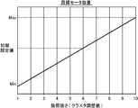
- FIG. 3 is a graph showing the relationship between the tilt switching pressure of the swing motor 10 and the tilt capacity in the swing work machine 100 according to the embodiment.
- the turning motor 10 in FIG. 3 is a swash plate type axial piston motor whose motor capacity changes as the tilt angle of the swash plate changes.
- the turning motor 10 is not limited to this type of motor.
- the motor capacity of the turning motor 10 is set to a preset default capacity when the capacity pilot pressure supplied to the pilot port 64 is the pressure Pb.
- the motor capacity of the swing motor 10 is set to a minimum capacity smaller than the default capacity when the capacity pilot pressure is equal to or lower than the pressure Pa, and is larger than the default capacity when the capacity pilot pressure is equal to or higher than the pressure Pc. Set to maximum capacity.
- the motor capacity of the swing motor 10 can be set to any value from the minimum capacity to the maximum capacity by changing the capacity pilot pressure between the pressure Pa and the pressure Pc.
- the default capacity is a preset value for the motor capacity of the turning motor 10.
- the default capacity is a value set in advance for the deceleration of the turning of the upper turning body.
- the default capacity is a motor capacity that is used when the turning of the upper-part turning body 2 is in a deceleration state.
- the default capacity is a value smaller than the maximum capacity of the motor capacity and larger than the minimum capacity.
- the default capacity is a motor capacity set in advance so as to reduce both the load on the equipment due to overtorque and insufficient brake torque when braking the swing motor 10 by the brake circuit described above, and is based on the characteristics of the swing work machine 100. Is set as appropriate. Data corresponding to the default capacity is stored in the control device 70.
- the control device 70 is constituted by a microcomputer, for example.
- the control device 70 includes a central processing unit (Central Processing Unit), a ROM (Read Only Memory) that stores various control programs, a RAM (Random Access Memory) used as a work area of the CPU, and the like.
- Central Processing Unit Central Processing Unit
- ROM Read Only Memory
- RAM Random Access Memory
- FIG. 4 is a block diagram showing a functional configuration of the revolving work machine 100 according to the embodiment.
- the control device 70 includes a differential pressure calculation unit 71, a capacity control unit 72, and a turning state determination unit 73 as functions.
- the control device 70 operates such that the differential pressure calculation unit 71, the capacity control unit 72, and the turning state determination unit 73 are functionally configured by the CPU executing the control program.
- the control device 70 executes the control program based on signals input from the operating oil pressure detectors 81A and 81B, the turning operation detectors 82A and 82B, the turning speed detector 83, the pump operating pressure detector 84, and the like.
- the operation of the turning work machine 100 (the operation of the turning motor 10 and the like) is controlled.
- the differential pressure calculation unit 71 has a function of calculating a motor differential pressure ⁇ P (effective differential pressure ⁇ P) of the swing motor 10 based on detection values detected by the hydraulic pressure detectors 81A and 81B. Specifically, it is as follows.
- the turning state determination unit 73 has a function of determining the turning state of the upper turning body 2. The function of the turning state determination unit 73 will be described later based on the flowchart shown in FIG.
- the capacity control unit 72 has a function of controlling the motor capacity of the turning motor 10.
- the capacity control unit 72 controls the motor capacity so that the motor capacity of the turning motor 10 becomes a set capacity during the combined operation. Thereby, the turning operation of the upper turning body 2 becomes suitable for the preference of the operator during the combined operation.
- the capacity control unit 72 sets the motor capacity to the default regardless of whether the combined operation is being performed.
- the motor capacity is controlled so as to be the capacity. This is due to over-torque that may occur when the motor capacity of the swing motor 10 is set to a preset first set capacity larger than the default capacity when the upper swing body 2 is decelerated.
- the set capacity is a capacity of the motor set for the combined operation.
- the set capacity may be a preset value.
- the set capacity is a value set according to, for example, the load of the swing operation of the upper swing body 2, the load of the attachment (for example, the boom 4), the posture of the swing work machine 100, etc. It may be a fluctuation value that fluctuates according to the state). Specific examples are as follows.
- the capacity control unit 72 can set, for example, the motor capacity at the time of composite operation based on a preset target motor capacity as follows.
- FIG. 5 is a graph illustrating a setting example of the target motor capacity of the swing motor 10 in the swing work machine 100 according to the embodiment.
- the vertical axis represents the motor capacity of the turning motor 10 and the horizontal axis represents the turning strength (cluster adjustment value) of the turning motor 10.
- the turning strength of the horizontal axis in FIG. 5 indicates that the operator can select the turning acceleration of the upper turning body 2 according to his / her preference during the combined operation in which the turning action of the upper turning body 2 and the raising / lowering action of the boom 4 are performed simultaneously. It is.
- the turning strength is divided into a plurality of levels (for example, 10 levels).
- the revolving operation of the upper revolving structure 2 and the raising / lowering operation of the boom 4 should be given priority to the revolving operation of the upper revolving structure 2 according to workability, work application, operation skill, etc.
- each operator may have a preference for operation, for example, when priority is given to the hoisting operation of the boom 4. For example, when the operator wants to prioritize the turning motion of the upper swing body 2 during the combined operation, the operator selects a higher step from the 10 steps, and when the operator wants to prioritize the hoisting operation of the boom 4 during the combined operation. Select the lowest step from the list.
- the operator selects a turning strength level from 10 levels using an operation panel (not shown).
- a signal corresponding to the selected level is input to the control device 70.
- the control device 70 a motor capacity corresponding to the turning strength at each stage is stored in advance.
- the motor capacity is set and controlled as follows, for example. That is, the capacity setting unit provided as a function of the control device 70 has a capacity corresponding to the turning strength selected by the operator from among the motor capacities corresponding to a plurality of steps of turning strength stored in the control device 70 in advance. Is set to the set capacity (target motor capacity) at the time of the composite operation, and the control device 70 stores the set capacity. And the capacity
- the capacity control unit 72 adjusts the capacity pilot pressure supplied to the pilot port 64 by controlling the pilot pressure operation valve 68 so that the motor capacity becomes the set capacity.
- the motor capacity of the swing motor 10 is automatically set to the set capacity during the combined operation in which the swing operation of the upper swing body 2 and the raising / lowering operation of the boom 4 are performed simultaneously.
- the “initial setting value” on the vertical axis in FIG. 5 is an initial value of the motor capacity that is automatically set when the turning work machine 100 is started. Further, “MAX” on the vertical axis in FIG. 5 is a motor capacity corresponding to the maximum capacity in FIG. 3, and “Min” on the vertical axis is a motor capacity corresponding to the minimum capacity in FIG. Therefore, when the operator does not set the turning strength level or before setting the turning strength level, the motor capacity is set to the initial setting value.
- the initial setting value of the motor capacity in FIG. 5 is the same value as the default capacity in FIG. However, the initial setting value may be a value different from the default capacity.
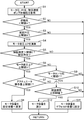
- FIG. 6 is a flowchart showing an example of control in the swing work machine 100 according to the embodiment.
- the control device 70 reads various detection signals input thereto (step S1). Specifically, the control device 70 detects the first motor pressure detection signal and the second motor pressure detection signal detected by the operating oil pressure detectors 81A and 81B, and the turning pilot pressure detected by the turning operation detection units 82A and 82B. The detection signal, the turning speed detection signal corresponding to the turning speed of the upper turning body 2 detected by the turning speed detector 83, the turning direction, and the second hydraulic pump detected by the pump operating pressure detector 84 The operating pressure detection signal corresponding to the operating pressure of 32 is acquired. The control device 70 stores data relating to these signals.
- the control device 70 determines whether or not the operating pressure of the second hydraulic pump 32 is less than a preset threshold A based on the operating pressure detection signal (step S2).
- the capacity control unit 72 sets the motor capacity of the turning motor 10 to a default capacity (step S11). That is, by setting the motor capacity of the swing motor 10 to the default capacity when the operating pressure of the second hydraulic pump 32 is a large pressure equal to or higher than the threshold A, the swing torque of the swing motor 10 is prevented from becoming too large. Can do.
- the turning state determination unit 73 determines that the turning pilot pressure is equal to or higher than the preset threshold value B based on the turning pilot pressure detection signal. It is determined whether or not (step S3).
- the capacity control unit 72 sets the motor capacity of the turning motor 10 to the default capacity (step S11). ).
- the differential pressure calculation unit 71 is detected by the hydraulic pressure detectors 81A and 81B. Based on the motor pressure detection signal corresponding to the value, the motor differential pressure ⁇ P (effective differential pressure ⁇ P) of the swing motor 10 is calculated (step S4).
- the control device 70 stores the calculation result.
- the turning state determination unit 73 determines the turning speed (upper turning) of the turning motor 10 based on the turning speed detection signal corresponding to the turning speed of the upper turning body 2 detected by the turning speed detector 83 and the turning direction. It is determined whether or not the turning speed of the body 2 exceeds a preset threshold C, and the turning direction of the turning motor 10 (the turning direction of the upper turning body 2) is the turning operation of the turning operation lever 12a by the operator. It is determined whether or not the direction matches (step S5).
- the capacity control unit 72 turns The motor capacity of the motor 10 is set to a default capacity (step S11).
- the turning direction of the turning motor 10 is opposite to the direction of the turning operation by the operator (NO in step S5), that is, when the operator is operating the turning operation lever 12a in the direction of the so-called reverse lever.
- the capacity control unit 72 sets the motor capacity of the turning motor 10 to the default capacity (step S11).
- the turning state is determined.
- the unit 73 determines whether or not the motor differential pressure ⁇ P is greater than or equal to a preset threshold value D (step S6). That is, when the upper swing body 2 is swinging and the operator operates the swing operation lever 12a in the same direction as the swing direction of the upper swing body 2 (when turning in the operation direction), the swing state The determination unit 73 determines whether or not the motor differential pressure ⁇ P is greater than or equal to a preset threshold value D (step S6).
- control device 70 When motor differential pressure ⁇ P is greater than or equal to threshold value D (YES in step S6), control device 70 has an operation amount of the operating lever by the operator for operating boom cylinder 7 (actuator) greater than or equal to preset threshold value E. It is determined whether or not there is (step S7).
- step S7 When the operation amount regarding the boom cylinder 7 is equal to or greater than the threshold value E (YES in step S7), that is, a combined operation in which the turning operation for operating the turning motor 10 and the undulation operation for operating the boom cylinder 7 is performed simultaneously. If so, the capacity control unit 72 changes the motor capacity to the set capacity (step S8). Then, the control device 70 repeats the above series of flows (steps S1 to S12).
- the set capacity does not necessarily have to be set based on the motor capacity setting example shown in FIG. 5 described above, and can be set by various methods. When the set capacity is set based on, for example, the setting example of the motor capacity shown in FIG. 5, the level of the turning strength selected in advance before the operator operates the turning work machine 100 (see FIG. 5). ) Is the set capacity.
- step S7 If the operation amount related to the boom cylinder 7 is less than the threshold value E (NO in step S7), the capacity control unit 72 performs control to set the motor capacity to the default capacity (step S11). That is, when an operation in which only the turning operation for operating the turning motor 10 is performed (during the turning operation alone), the capacity control unit 72 performs control to set the motor capacity to the default capacity (step S11). Then, the control device 70 repeats the above series of flows (steps S1 to S12).
- the condition that the motor differential pressure ⁇ P is less than the threshold value D can be an index indicating that the rotation speed of the swing motor 10 is decreased, and can be an index indicating the possibility of cavitation. sell. Therefore, when the motor differential pressure ⁇ P is less than the threshold value D, the turning state determination unit 73 determines the meter-out side pressure (M / O pressure), that is, the port on the side from which the working oil of the turning motor 10 is discharged. It is determined whether or not the hydraulic oil pressure is less than a preset threshold value F (step S9).
- the turning state determination unit 73 determines that the turning speed of the turning motor 10 is based on the turning speed detection signal detected by the turning speed detector 83. It is determined whether or not it is equal to or higher than the turning speed of the turning motor 10 detected last time (step S10). That is, when no brake pressure is generated in the pipe line (the pipe line 14 or the pipe line 15) connected to the port on the side from which the hydraulic oil of the turning motor 10 is discharged, the turning state determination unit 73 detects the turning speed.
- the turning speed of the turning motor 10 is equal to or higher than the turning speed of the turning motor 10 detected last time based on the turning speed detection signal corresponding to the magnitude of the turning speed of the upper turning body 2 and the turning direction detected by the device 83. It is determined whether or not there is (step S10).
- step S10 When the turning speed of the turning motor 10 is equal to or higher than the turning speed of the turning motor 10 detected last time (YES in step S10), that is, when the turning speed of the upper turning body 2 has not decreased, the capacity control unit 72 Control to reduce the motor capacity is performed (step S12). Then, the control device 70 repeats the above series of flows (steps S1 to S12).
- the deceleration determination condition regarding the direction of the turning operation detected by the turning operation detectors 82A and 82B, the turning speed detected by the turning speed detector 83, and the differential pressure ⁇ P calculated by the differential pressure calculator 71. Is preset. In the present embodiment, even when the deceleration determination condition is satisfied and it is determined that the upper-part turning body 2 is in a deceleration state (YES in step S3, YES in step S5, NO in step S6), Further, the pressure of the hydraulic oil at the port from which the hydraulic oil is discharged is less than a preset threshold value F (YES in step S9), and the turning speed of the upper swing body 2 has not decreased (YES in step S10). ) Is satisfied, the capacity control unit 72 controls the motor capacity so that the capacity of the turning motor 10 decreases (step S12). Thereby, it is possible to suppress the occurrence of cavitation.
- the capacity control unit 72 can perform control to gradually decrease the motor capacity of the turning motor 10 from the set capacity or the default capacity toward the minimum capacity. Then, while the control device 70 repeats the above series of flows (steps S1 to S12), when the cavitation determination condition is not satisfied in the hydraulic circuit, the capacity control unit 72 decreases the motor capacity of the swing motor 10. The control to be stopped can be stopped. Further, when the cavitation determination condition is satisfied, for example, the capacity control unit 72 reduces the motor capacity of the turning motor 10 in one step from the set capacity or the default capacity to the minimum capacity instead of stepwise as described above. May be.
- the capacity control unit 72 performs control to set the motor capacity to the default capacity (step S11). That is, when the brake pressure is generated in the pipe line (the pipe line 14 or the pipe line 15) connected to the port on the side from which the hydraulic oil of the swing motor 10 is discharged (when the upper swing body 2 is in the deceleration state) ), The capacity control unit 72 performs control to set the motor capacity to the default capacity (step S11). Then, the control device 70 repeats the above series of flows (steps S1 to S12).
- the capacity control unit 72 performs control to set the motor capacity to the default capacity (step S11). That is, when no brake pressure is generated in the pipe line connected to the port on the hydraulic oil discharge side of the turning motor 10 and the turning speed of the upper turning body 2 is reduced, the capacity control unit 72 performs control to set the motor capacity to the default capacity (step S11). Then, the control device 70 repeats the above series of flows (steps S1 to S12).
- the capacity control unit 72 is configured to be able to control the motor capacity to the set capacity so that the capacity is different from the default capacity during the combined operation. 4 can be operated in a state that matches the situation of the complex operation and the operator's preference.
- the capacity control unit 72 determines the motor capacity regardless of whether or not the combined operation is being performed.
- the motor capacity is controlled to be the default capacity. This can reduce the load on the equipment due to overtorque that occurs when the motor capacity of the swing motor 10 is a first capacity larger than the default capacity when the upper swing body 2 is decelerated.
- the upper swing body 2 performs the swing operation based on the swing pilot pressure detected by the swing operation detection units 82A and 82B and the swing speed of the upper swing body 2 detected by the swing speed detector 83. It can be determined whether or not the vehicle is turning in the operation direction. That the effective differential pressure ⁇ P detected by the operating oil pressure detectors 81A and 81B is less than a preset threshold value D can be an index indicating that the rotational speed of the swing motor 2 is reduced. Therefore, even if it is determined that the upper swing body 2 is turning in the operation direction of the swing operation, if the condition that the effective differential pressure ⁇ P is less than the threshold D is satisfied, the upper swing body 2 It can be determined that there is a possibility of the deceleration state.
- the present embodiment not only the above-described determination of the deceleration state of the turning of the upper-part turning body 2 but also the possibility of cavitation can be determined.
- the motor capacity By controlling the motor capacity based on the determination of cavitation, it is possible to suppress the occurrence of cavitation.
- a preset threshold F is connected to the port. This can be an index indicating that no brake pressure is generated in the pipe line 14 or the pipe line 15.
- cavitation may occur in the hydraulic circuit.
- the upper revolving body 2 may turn while increasing the turning speed in the direction in which the gravity acts due to gravity.
- the absorption flow rate of the hydraulic oil supplied to the turning motor 10 is smaller than the flow rate corresponding to the actual turning speed of the upper turning body 2, cavitation may occur in the hydraulic circuit. There is sex.
- the pressure on the meter-out side is less than the threshold value F, and
- the capacity control unit 72 determines that the turning motor 72 The motor capacity is controlled so that the capacity of 10 decreases. Thereby, it is possible to suppress the occurrence of cavitation.
- the deceleration determination condition described above that is, the direction of the turning operation detected by the turning operation detectors 82A and 82B, the turning speed detected by the turning speed detector 83, and the differential pressure differential pressure calculator 71. Is set in advance as to the deceleration determination condition regarding the differential pressure ⁇ P of the swing motor calculated by the above.
- the capacity control unit 72 turns the turning motor so that the motor capacity becomes the default capacity. 10 capacity is controlled. Accordingly, it is possible to always obtain a stable braking performance (stopping performance) by the brake circuit when decelerating the turning of the upper swing body 2 while improving the accuracy of determining the deceleration state of the upper swing body 2.
- the fact that the pressure on the meter-out side is less than the threshold value F indicates that the pipe line 14 connected to the port on the side from which the hydraulic oil of the swing motor 10 is discharged or as described above. This can be an index indicating that no brake pressure is generated in the pipe line 15.
- the fact that the pressure on the meter-out side is less than the threshold value F can be an index indicating that the brake pressure tends to increase but the brake pressure has not yet reached the threshold value F. Therefore, in the present embodiment, the pressure on the meter-out side is less than the threshold value F, and the turning state determination unit 73 compares the turning speeds detected by the turning speed detector 83 a plurality of times to compare the upper turning body.
- the capacity control unit 72 controls the capacity of the turning motor 10 so that the motor capacity becomes the default capacity. That is, in such a case, the meter-out side pressure, that is, the brake pressure, does not reach the threshold value F, but the turning speed of the upper swing body 2 is actually decreasing, so the swing of the upper swing body 2 is decelerated. It is determined that it is in a state. In such a case, the capacity control unit 72 controls the capacity of the turning motor 10 so that the motor capacity becomes the default capacity. Accordingly, it is possible to always obtain a stable braking performance (stopping performance) by the brake circuit when decelerating the turning of the upper swing body 2 while improving the accuracy of determining the deceleration state of the upper swing body 2.
- the operator selects the turning strength according to his / her preference, and the motor capacity of the turning motor 10 is set to the selected target motor capacity (set capacity) at the time of composite operation.
- the present invention is not limited to this.
- the set capacity related to the motor capacity of the swing motor 10 during the combined operation is changed according to, for example, the load of the swing operation of the upper swing body 2, the load of the attachment (for example, the boom 4), the posture of the swing work machine 100, and the like. May be.
- step S7 of the flowchart shown in FIG. 6 when an operation in which only the turning operation for operating the turning motor 10 is performed (during the turning single operation), the capacity control unit 72 sets the motor capacity.
- the motor capacity may be set to a preset set capacity for a single turn operation that is different from the default capacity.
- the turning state determination unit 73 determines whether or not the turning speed of the turning motor 10 is equal to or higher than the turning speed of the turning motor 10 detected last time. Although it is determined whether or not the turning speed of the upper swing body 2 is decreasing, the present invention is not limited to this.
- the turning state determination unit 73 may compare three or more turning speeds detected by the turning speed detector 83 to determine whether or not the turning speed of the upper turning body 2 is decreasing.
- the turning operation detectors 82A and 82B are configured by the right turning pilot pressure sensor 82A and the left turning pilot pressure sensor 82B is illustrated, but the present invention is not limited thereto.
- the turning operation detection unit is included in the control device. You may comprise as a turning operation detection function.
- a turning work machine capable of obtaining a stable brake characteristic when the turning of the upper turning body is decelerated while the motor capacity is set to a capacity suitable for the combined operation during the combined operation.
- the provided swivel work machine includes a base, an upper swing body mounted on the base so as to be rotatable, an attachment mounted on the upper swing body, and a hydraulic pump that discharges hydraulic oil.
- a swiveling motor comprising a variable displacement hydraulic motor that operates to swivel the upper swivel body in response to the supply of the hydraulic oil discharged from the hydraulic pump; and the hydraulic oil discharged from the hydraulic pump.
- An actuator that operates to operate the attachment in response to the supply; a brake circuit that brakes the swing motor to decelerate the swing of the upper swing body; and whether the swing of the upper swing body is in a deceleration state
- a turning state determining unit for determining whether or not, and a capacity control unit for controlling a motor capacity that is a capacity of the turning motor constituting the turning motor.
- the capacity control unit sets the motor capacity to a capacity set for the composite operation during a composite operation in which an operation for turning the upper swing body and an operation for operating the attachment are performed simultaneously.
- the turning state determination unit determines that the turning of the upper turning body is in a deceleration state, the motor capacity is set to a preset default capacity even during the combined operation. It is configured.
- the capacity control unit sets the motor capacity to the capacity set for the composite operation during the composite operation, so that the upper swing body and the attachment can be adjusted to the situation of the composite operation and the operator's preference.
- the turning state determination unit determines that the turning of the upper-part turning body is in a decelerating state, regardless of whether the combined operation is being performed or not.
- the brake characteristics can be kept constant. Therefore, the operator can safely stop the upper swing body by decelerating the swing of the upper swing body with stable brake characteristics.
- the swing motor has a first port and a second port, and receives supply of the hydraulic oil to one of the first port and the second port.
- the turning work machine is configured to rotate in a direction corresponding to the one port and to discharge the hydraulic oil from the other port.
- An operation device a turning operation detection unit for detecting a direction of the turning operation given to the turning operation device, a turning speed detector for detecting a turning speed of the upper turning body, and the hydraulic oil in the first port.
- a hydraulic pressure detector for detecting a pressure and a pressure of the hydraulic oil in the second port; and the swing speed and the hydraulic pressure detector detected by the swing speed detector Therefore, based on the detected hydraulic oil pressure, a differential pressure for calculating a differential pressure of the swing motor, which is a difference between the hydraulic oil pressure at the first port and the hydraulic oil pressure at the second port.
- a calculation unit, and the turning state determination unit includes a direction of the turning operation detected by the turning operation detection unit, the turning speed detected by the turning speed detector, and the differential pressure calculation unit. It is preferable to determine whether or not the turning of the upper-part turning body is in a decelerating state based on the calculated differential pressure.
- the turning state determination unit is configured to turn the upper turn based on the direction of the turning operation detected by the turning operation detection unit and the turning speed detected by the turning speed detector. It is determined whether the body is turning in the operation direction of the turning operation, the upper turning body is turning in the operation direction of the turning operation, and the difference calculated by the differential pressure calculation unit It is preferable that when the pressure is less than a preset threshold value, it is determined that the turning of the upper turning body is in a deceleration state.
- the turning speed detector can detect the turning speed of the upper turning body, that is, the magnitude of the turning speed and the turning direction. Therefore, the turning state determination unit performs the turning operation of the upper turning body based on the direction of the turning operation detected by the turning operation detection unit and the turning speed (size and direction) of the upper turning body detected by the turning speed detector. It can be determined whether or not the vehicle is turning in the direction of.
- the differential pressure (effective differential pressure) of the swing motor calculated by the differential pressure calculation unit is small, that is, when the differential pressure is less than a preset threshold value, the rotational speed of the swing motor decreases. It can be an indicator to represent. Therefore, the turning state determination unit can determine the possibility of a deceleration state of the upper turning body based on the differential pressure when the upper turning body is turning in the operation direction of the turning operation.
- the capacity control unit may be configured such that the hydraulic oil is discharged even when the turning state determination unit determines that the turning of the upper revolving body is in a deceleration state.
- the motor capacity is set so that the capacity of the swing motor decreases. It is preferable to control.
- the capacity control unit is further configured to satisfy the cavitation determination condition.
Abstract
旋回式作業機械(100)は、上部旋回体(2)の旋回が減速状態にあるか否かを判定する旋回状態判定部(73)と、モータ容量を制御する容量制御部(72)を備える。容量制御部(72)は、上部旋回体(2)を旋回させるための操作とアタッチメント(4)を動作させるための操作とが同時に行われる複合操作時には、前記モータ容量を前記複合操作のために設定される容量にする一方で、旋回状態判定部(73)によって上部旋回体(2)の旋回が減速状態にあると判定された場合には、前記複合操作時であっても前記モータ容量を予め設定されたデフォルト容量にするように構成されている。
Description
本発明は、油圧ショベル等の旋回式作業機械に関するものである。
旋回式作業機械は、一般に、下部走行体と、当該下部走行体に旋回可能に搭載される上部旋回体と、上部旋回体に装着されるアタッチメントと、前記上部旋回体を旋回させる油圧モータである旋回モータと、当該旋回モータに供給されるべき作動油を吐出する油圧ポンプと、当該油圧ポンプと前記旋回モータとの間に介在する旋回制御弁と、を備える。旋回制御弁は、オペレータによる旋回操作レバーの操作に応じて開閉作動し、前記油圧ポンプから吐出される作動油のうち前記旋回モータに供給される作動油の流量を変化させる。
前記油圧ポンプが吐出する作動油は、前記旋回モータだけでなくそれ以外の他の油圧アクチュエータ(例えばブームシリンダ)にも用いられる場合が多い。この場合、当該他の油圧アクチュエータは前記旋回制御弁とは別の専用のコントロールバルブを介して前記油圧ポンプに接続される。すなわち、前記油圧ポンプは前記旋回モータへの作動油の供給と前記他の油圧アクチュエータへの作動油の供給とに兼用される。
このようなタイプの作業機械では、旋回モータを作動させる旋回操作と前記他の油圧アクチュエータを作動させる操作とが同時に行われる時すなわち複合操作時において、前記油圧ポンプから前記旋回モータ及び前記他の油圧アクチュエータに供給される作動油の流量の分配が重要となる。例えば特許文献1は、1台の油圧ポンプからブームシリンダと旋回用油圧モータに作動油を供給してこれらを駆動する油圧装置を開示している。特許文献1の油圧装置では、旋回モータの傾転容量を調整することにより、旋回用油圧モータと他のアクチュエータの作動を制御している。
前記のように複合操作時に旋回モータのモータ容量を変化させる制御が行われると、旋回減速時における前記旋回モータの制動特性がそのモータ容量に応じて変わるので、安定した減速動作ができなくなる。これに関し、減速時のブレーキ特性は安全上安定したものであることが望まれる。
本発明の目的は、複合操作時にはモータ容量を当該複合操作に適した容量にする一方で、上部旋回体の旋回が減速するときには安定したブレーキ特性を得ることが可能な旋回式作業機械を提供することにある。
提供されるのは、旋回式作業機械であって、基体と、前記基体の上に旋回可能となるように搭載される上部旋回体と、前記上部旋回体に搭載されるアタッチメントと、作動油を吐出する油圧ポンプと、可変容量型油圧モータからなり、前記油圧ポンプから吐出される前記作動油の供給を受けて前記上部旋回体を旋回させるように作動する旋回モータと、前記油圧ポンプから吐出される前記作動油の供給を受けて前記アタッチメントを動作させるように作動するアクチュエータと、前記上部旋回体の旋回を減速させるように前記旋回モータを制動するブレーキ回路と、前記上部旋回体の旋回が減速状態にあるか否かを判定する旋回状態判定部と、前記旋回モータを構成する前記旋回モータの容量であるモータ容量を制御する容量制御部と、を備える。前記容量制御部は、前記上部旋回体を旋回させるための操作と前記アタッチメントを動作させるための操作とが同時に行われる複合操作時には、前記モータ容量を前記複合操作のために設定された容量にする一方で、前記旋回状態判定部によって前記上部旋回体の旋回が減速状態にあると判定された場合には、前記複合操作時であっても前記モータ容量を予め設定されたデフォルト容量にするように構成されている。
本発明の好ましい実施の形態を、図面を参照しながら説明する。
図1は、本発明の実施形態に係る旋回式作業機械100としての油圧ショベルを示す側面図である。旋回式作業機械100は、基体を構成するクローラ式の下部走行体1と、その走行面に対して垂直な旋回中心軸Zまわりに旋回自在に搭載される旋回体である上部旋回体2と、この上部旋回体2に装着されるアタッチメントと、当該アタッチメントを動作させるための油圧アクチュエータと、を備える。
本実施形態では、前記アタッチメントは、上部旋回体2に起伏可能に装着されるブーム4と、このブーム4の先端に取付けられたアーム5と、このアーム5の先端に取付けられたバケット6とを含む。前記油圧アクチュエータは、ブーム4を動作させるためのブームシリンダ7と、アーム5を動作させるためのアームシリンダ8と、バケット6を動作させるためのバケットシリンダ9とを含む。
本発明に係る旋回式作業機械は上記のような油圧ショベルに限定されない。本発明は、下部走行体1及びこれに旋回可能に搭載される上部旋回体2を含む種々の旋回式作業機械(例えば旋回式クレーン)に適用されることが可能である。したがって、前記アタッチメント及び前記油圧アクチュエータは、旋回式作業機械の種類に応じて適宜選定される。また、前記基体は下部走行体1のように走行可能なものに限定されず、特定の場所に設置されて旋回体を支持する基台であってもよい。
図2は、実施形態に係る旋回式作業機械100に搭載された油圧回路を示す図である。この油圧回路は、上部旋回体2の旋回駆動及びブーム4の起伏駆動に関与する部分を示す。当該油圧回路は、上部旋回体2を旋回駆動させるための油圧モータである旋回モータ10と、ブーム4を起伏駆動させるための油圧アクチュエータ7(ブームシリンダ7)と、エンジン101の出力軸に連結される油圧ポンプ30及びパイロットポンプ33と、コントロールバルブユニット40と、を備える。
旋回モータ10は、作動油の供給を受けて回転する出力軸10cを有し、当該出力軸10cは上部旋回体2を左右双方向に旋回させるように上部旋回体2に連結されている。具体的に、旋回モータ10は、第1ポート10a及び第2ポート10bを有し、そのうちの一方のポートへの作動油の供給を受けることにより当該一方のポートに対応する方向に出力軸10cが回転するとともに他方のポートから作動油を排出する。
ブームシリンダ7は、その伸長及び収縮によりブーム4を上げ方向及び下げ方向にそれぞれ動かすように当該ブーム4と上部旋回体2との間に介在する。
油圧ポンプ30は、旋回モータ10及びブームシリンダ7を動作させるための作動油を吐出する。本実施形態では、油圧ポンプ30は、複数の油圧ポンプ、具体的には第1油圧ポンプ31と、第2油圧ポンプ32とを含む。ただし、油圧ポンプ30は、1つの油圧ポンプのみによって構成されていてもよい。
第1油圧ポンプ31、第2油圧ポンプ32及びパイロットポンプ33は、いずれもエンジン101によって駆動され、これにより図略のタンク内の作動油を吐出する。具体的には、第1及び第2油圧ポンプ31,32は、ブームシリンダ7を動作させるための作動油を吐出する。また、第2油圧ポンプ32は、旋回モータ10を動作させるための作動油を吐出する。すなわち、上部旋回体2を旋回させる旋回モータ10と、ブーム4を動作させるブームシリンダ7とが共通の第2油圧ポンプ32に接続されている。
パイロットポンプ33は、後述するコントロールバルブユニット40に設けられる複数の制御弁にこれらを開閉作動させるためのパイロット圧を供給するためのパイロット油を吐出する。
コントロールバルブユニット40は、油圧ポンプ30と旋回モータ10との間に介在し、油圧ポンプ30から旋回モータ10に供給される作動油の方向及び流量を変化させるように作動する。また、コントロールバルブユニット40は、油圧ポンプ30とブームシリンダ7との間に介在し、油圧ポンプ30からブームシリンダ7に供給される作動油の方向及び流量を変化させるように作動する。コントロールバルブユニット40は、このような機能を有していればよく、具体的な構成は特に限定されるものではない。コントロールバルブユニット40の一例を挙げると次の通りである。
コントロールバルブユニット40は、例えば、図略のブーム1速制御弁と、ブーム2速制御弁と、旋回制御弁とを含む。
前記ブーム1速制御弁は、第1油圧ポンプ31とブームシリンダ7との間に介在し、ブームシリンダ7を駆動するための作動油を第1油圧ポンプ31からブームシリンダ7に導くとともに当該作動油の方向及び流量を制御するための制御弁である。
前記ブーム2速制御弁は、第2油圧ポンプ32とブームシリンダ7の間に介在し、ブーム1速制御弁を通じてブームシリンダ7に供給される作動油に加え、ブーム4の駆動に関してその増速のための作動油を第2油圧ポンプ32からブームシリンダ7に導くとともに当該作動油の方向及び流量を制御するための制御弁である。
前記旋回制御弁は、第2油圧ポンプ32と旋回モータ10との間に介在し、旋回モータ10を駆動するための作動油を第2油圧ポンプ32から旋回モータ10の第1ポート10a及び第2ポート10bの何れか一方に導く。すなわち、前記旋回制御弁は、当該旋回モータ10に供給される作動油の方向及び流量を制御するための制御弁である。
これらの制御弁のそれぞれは、パイロット操作式の油圧切換弁からなり、各制御弁のパイロットポートにパイロットポンプ33からのパイロット圧の供給を受け、当該パイロット圧の大きさに対応したストロークで開弁することにより、当該ストロークに対応した流量で旋回モータ10又はブームシリンダ7に作動油が供給されることを許容する。従って、当該パイロット圧を変えることによって前記流量の制御が可能である。
図2に示す油圧回路は、旋回操作装置12と、右旋回管路14と、左旋回管路15と、リリーフ弁回路18と、チェック弁回路21と、連通路22と、メイクアップライン23とをさらに含む。
旋回操作装置12は、旋回操作レバー12aと、パイロット弁12bと、を有する。旋回操作レバー12aは、操作部材であり、当該旋回操作レバー12aに対してオペレータから旋回指令操作が与えられることによりその向きに回動する。パイロット弁12bは、パイロットポンプ33に接続される図略の入口ポートと、一対の出口ポートと、を有する。当該一対の出口ポートは、図略の右旋回パイロットライン及び左旋回パイロットラインをそれぞれ介して前記コントロールバルブユニット40の旋回制御弁における図略の右旋回パイロットポート及び左旋回パイロットポートに接続される。パイロット弁12bは、旋回操作レバー12aに連結されている。パイロット弁12bは、前記右旋回パイロットポート及び前記左旋回パイロットポートのうち旋回操作レバー12aに与えられる旋回指令操作の向きに対応するパイロットポートに対してパイロットポンプ33から当該旋回指令操作の大きさに対応したパイロット圧が供給されることを許容するように開弁する。なお、旋回操作装置12は、便宜上図2に示す位置に記載されているが、実際にはパイロットポンプ33とコントロールバルブユニット40(具体的には旋回制御弁)との間に介在する。
リリーフ弁回路18、チェック弁回路21、連通路22及びメイクアップライン23は、旋回モータ10を制動させるためのブレーキ回路を構成する。なお、旋回モータ10を制動させるためのブレーキ回路は、図2に示す構成に限られない。
リリーフ弁回路18は、旋回モータ10をバイパスして右旋回管路14と左旋回管路15とを相互に接続する。リリーフ弁回路18は、左旋回リリーフ弁16及び右旋回リリーフ弁17を含む。左旋回リリーフ弁16及び右旋回リリーフ弁17は、左旋回リリーフ弁16の入口ポートが右旋回管路14に接続され、右旋回リリーフ弁17の入口ポートが左旋回管路15に接続され、かつ両リリーフ弁16,17の出口ポートが相互に接続されるように、配置される。
チェック弁回路21は、リリーフ弁回路18よりも旋回モータ10に近い位置で両旋回管路14,15同士を相互に接続する。当該チェック弁回路21は、左旋回チェック弁19及び右旋回チェック弁20を含む。左旋回チェック弁19は右旋回管路14からの作動油の流入を阻止する向きに配置され、右旋回チェック弁20は左旋回管路15からの作動油の流入を阻止する向きに配置される。
連通路22は、リリーフ弁回路18のうち左旋回リリーフ弁16及び右旋回リリーフ弁17同士の間に位置する部位と、チェック弁回路21のうち左旋回チェック弁19及び右旋回チェック弁20同士の間に位置する部位とを接続する。メイクアップライン23は、連通路22が負圧になったときに当該メイクアップライン23を通じてタンク24から連通路22に作動油が吸い上げられることを許容してキャビテーションを防止するように連通路22とタンク24とを相互に接続する。当該メイクアップライン23には図略の背圧弁が設けられている。
この油圧回路において、例えば右旋回駆動中に旋回操作レバー12aが中立位置に戻されてコントロールバルブユニット40の旋回制御弁がそれまでの右旋回位置から中立位置に復帰すると、当該旋回制御弁が両旋回管路14,15と油圧ポンプ30(具体的には第2油圧ポンプ32)との間を遮断するが、旋回モータ10は上部旋回体2の慣性によって右旋回方向の回転を続ける。このため、メータアウト側である左旋回管路15の圧力が上昇する。当該圧力が右旋回リリーフ弁17の設定圧に達すると当該右旋回リリーフ弁17が開弁して左旋回管路15の作動油が右旋回リリーフ弁17、連通路22、左旋回チェック弁19及び右旋回管路14を通じて旋回モータ10に流入することを許容する。このことは、前記慣性により回転を続ける旋回モータ10にリリーフ弁17の作用によるブレーキ力を与え、これにより当該旋回モータ10を減速させ、停止させる。左旋回からの減速時及び停止時もこれと同じである。
図2に示す油圧回路は、さらに、容量操作部50と、油圧供給制御部60と、容量パイロットライン69と、パイロット圧操作弁68と、制御装置70と、旋回パーキングブレーキ90と、複数のセンサとを備える。
複数のセンサは、作動油圧検出器81A,81Bと、旋回操作検出部82A,82Bと、旋回速度検出器83と、ポンプ作動圧検出器84とを含む。
作動油圧検出器81A,81Bは、旋回モータ10の第1ポート10aにおける作動油の圧力に対応する第1モータ圧検出信号を生成する第1モータ圧センサ81Aと、旋回モータ10の第2ポート10bにおける作動油の圧力に対応する第2モータ圧検出信号を生成する第2モータ圧センサ81Bとによって構成されている。作動油圧検出器81A,81Bは、モータ圧検出信号を制御装置70に入力する。
旋回操作検出部82A,82Bは、前記旋回制御弁の一対の旋回パイロットポートに入力される旋回パイロット圧にそれぞれ対応する旋回パイロット圧検出信号を生成する右旋回パイロット圧センサ82A及び左旋回パイロット圧センサ82Bによって構成されている。右旋回パイロット圧センサ82A及び左旋回パイロット圧センサ82Bは、それぞれ、右旋回パイロットライン26A及び左旋回パイロットライン26Bにおける右旋回パイロット圧及び左旋回パイロット圧に対応するパイロット圧検出信号を生成し、これを制御装置70に入力する。従って、当該右旋回パイロット圧センサ82A及び左旋回パイロット圧センサ82Bは、旋回操作装置12の旋回操作レバー12aに旋回指令操作が与えられたことを検出してその情報を制御装置70に与える。
旋回速度検出器83は、上部旋回体2の旋回速度の大きさ及び旋回の方向を検出することができるセンサである。旋回速度検出器83としては、例えば上部旋回体2の動作を検出可能なエンコーダ、レゾルバ、ジャイロセンサなどを用いることができる。旋回速度検出器83は、検出された上部旋回体2の旋回速度の大きさ、旋回方向などを電気的信号(旋回速度検出信号)に変換し、制御装置70に入力する。
ポンプ作動圧検出器84は、油圧ポンプ30(第2油圧ポンプ32)の作動圧に対応する作動圧検出信号を生成し、制御装置70に入力する。
旋回パーキングブレーキ90は、上部旋回体2が旋回モータ10により駆動されていないときに前記上部旋回体2を停止状態に保つように当該上部旋回体2に機械的な停止保持力を与えるためのブレーキ装置である。当該旋回パーキングブレーキ90は、前記上部旋回体2に前記停止保持力を与えるブレーキ状態と、当該上部旋回体2が旋回可能となるように当該上部旋回体2を解放するブレーキ解除状態とに切換可能である。
容量操作部50及び油圧供給制御部60は、制御装置70とともに容量制御装置を構成する。当該容量制御装置は、旋回操作レバー12aに与えられる旋回指令操作に応じて旋回モータ10の容量すなわち押しのけ容積を油圧によって制御するものである。
容量操作部50は、油圧供給制御部60により制御される容量操作用油圧の供給を受けて旋回モータ10の容量を変化させる。容量操作部50は、ピストン室を囲む容量操作シリンダ52と、当該容量操作シリンダ52の当該ピストン室に装填される容量操作ピストン54と、を有する。当該容量操作ピストン54は、前記ピストン室内において軸方向に変位することが可能であり、容量操作シリンダ52の内周面に対して摺動することが可能である。容量操作ピストン54は、当該軸方向の変位によって旋回モータ10のモータ容量を変化させるように旋回モータ10に連結される。例えば、旋回モータ10がアキシャルピストン型のものである場合、その斜板の傾きを変化させる。
具体的に、容量操作ピストン54は、容量操作ピストン54から第1油圧室55を貫くように延びるロッド53を介して旋回モータ10に連結される。容量操作ピストン54は、ピストン室52内を第1油圧室55と第2油圧室56とに区画し、当該第1油圧室55の容積を増加させる方向の変位(図1では右側への変位)に伴って旋回モータ10の容量を増大させる。当該容量操作ピストン54の軸方向の位置は、第1油圧室55に供給される第1容量操作用油圧と第2油圧室56に供給される第2容量操作用油圧とのバランスによって決定される。すなわち、第1容量操作用油圧に対して第2容量操作用油圧が低いほど容量操作ピストン54は旋回モータ10の容量を増大させる向き(図1では右向き)に変位する。
第1油圧室55において容量操作ピストン54が容量操作用油圧を受ける面積である受圧面積は前記ロッド53の断面積分だけ第2油圧室56における受圧面積よりも小さい。この断面積の差は、第1容量操作用油圧と第2油圧操作用油圧が同等のときに容量操作ピストン54を第2油圧室56の容積が最大となる位置、つまり旋回モータ10の容量を最小容量にする位置(図1では最も左側に位置)に保持することを可能にする。
油圧供給制御部60は、第1容量操作用油圧と第2容量操作用油圧の大小バランスを変えることにより容量操作ピストン54の位置を制御し、これにより、当該位置に対応する旋回モータ10の容量を制御する。
この実施形態に係る供給制御部60は、右旋回管路14又は左旋回管路15からの作動油を利用して容量操作部50に対する容量操作用油圧の供給と、当該容量操作用油圧の変更とを行う。供給制御部60は、図2に示されるような油圧供給ライン61と、第1分岐ライン61A及び第2分岐ライン61Bと、油圧供給制御弁62と、シャトル弁29とを含む。
油圧供給ライン61は、シャトル弁29と油圧供給制御弁62とを接続する。油圧供給ライン61は、シャトル弁29と油圧供給制御弁62との間の位置で分岐することにより、シャトル弁29と容量操作部50とを接続している。第1分岐ライン61Aは、右旋回管路14とシャトル弁29の第1入力部29aとを接続している。第2分岐ライン61Bは、左旋回管路15とシャトル弁29の第2入力部29bとを接続している。
シャトル弁29は、第1入力部29aおよび第2入力部29bのうち圧力が高い側と油圧供給ライン61とを連通させ、かつ、圧力が低い側と油圧供給ライン61とを遮断する。したがって、右旋回管路14及び左旋回管路15のうち圧力の高い側の管路から吐出される作動油を分岐ラインを通じて容量操作部50に導くことにより、当該容量操作部50の第1油圧室55及び第2油圧室56に容量操作用油圧を供給する。
具体的に、油圧供給ライン61は、第1油圧室55に接続される第1油圧ライン65と、第2油圧室56に接続される第2油圧ライン66と、に分岐している。油圧供給制御弁62は、第2油圧ライン66の途中に設けられている。油圧供給制御弁62は、当該油圧供給制御弁62に与えられる容量パイロット圧の大きさに対応した度合いで、第2油圧ライン66を通じて第2油圧室56に供給される第2容量操作用油圧を、第1油圧ライン65を通じて第1油圧室55に供給される第1容量操作用油圧に対して相対的に低下させる。
この実施形態に係る油圧供給制御弁62は、パイロット操作式のサーボ弁からなり、スリーブ62aと、当該スリーブ62a内に摺動可能に装填されるスプール62bと、当該スプール62bの軸方向の両側にそれぞれ配置されるバネ63及びパイロットポート64と、を有する。スプール62bは、パイロットポート64に容量パイロット圧が供給されないときはバネ63のバネ力により最大開口面積で第2油圧ライン66を開通する全開位置(図2の左側位置)に保持される。一方、スプール62bは、パイロットポート64に容量パイロット圧が供給されると当該容量パイロット圧の大きさに対応したストロークで全開位置から閉じ方向(図2では左向き)に変位して第2油圧室56に供給される第2容量操作用油圧を第1油圧室55に供給される第1容量操作用油圧に対して相対的に低下させる。
容量パイロットライン69は、パイロットポンプ33が吐出する作動油を油圧供給制御弁62のパイロットポート64に導くことにより当該パイロットポート64に容量パイロット圧を供給する。
パイロット圧操作弁68は、容量パイロットライン69の途中に設けられ、容量指令の入力を制御装置70から受けることにより当該容量指令の大きさに対応した開度で開弁し、これによりパイロットポート64に供給される容量パイロット圧を増大させる。この実施形態に係るパイロット圧操作弁68は、ソレノイド67を有する電磁比例弁からなる。ソレノイド67は、前記容量指令としての励磁電流の供給を受ける。
パイロット圧操作弁68は、ソレノイド67に前記励磁電流が供給されない(つまり容量指令が入力されない)ときは、容量パイロットライン69を遮断するように閉弁することにより当該パイロットポート64への前記容量パイロット圧の供給を阻止する。一方、パイロット圧操作弁68は、ソレノイド67に前記励磁電流が供給された(つまり容量指令が入力された)ときは、その励磁電流の大きさに対応した開度で前記容量パイロットライン69を開通して当該開度に対応した大きさの容量パイロット圧がパイロットポート64に供給されることを許容するように開弁する。
図3は、実施形態に係る旋回式作業機械100において、旋回モータ10の傾転切換圧と、傾転容量との関係を示すグラフである。図3における旋回モータ10は、斜板の傾転角が変わるとモータ容量が変わる斜板形アキシャルピストンモータである。ただし、旋回モータ10はこのタイプのモータに限られない。
旋回モータ10のモータ容量は、パイロットポート64に供給される容量パイロット圧が圧力Pbのときに、予め設定されているデフォルト容量に設定される。また、旋回モータ10のモータ容量は、容量パイロット圧が圧力Pa以下のときに、前記デフォルト容量よりも小さい最小容量に設定され、容量パイロット圧が圧力Pc以上のときに、前記デフォルト容量よりも大きい最大容量に設定される。このように旋回モータ10のモータ容量は、容量パイロット圧を圧力Paから圧力Pcの間で変えることにより、最小容量から最大容量までの任意の値に設定可能である。
デフォルト容量は、旋回モータ10のモータ容量に関して予め設定された値である。デフォルト容量は、上部旋回体の旋回の減速のために予め設定された値である。言い換えると、デフォルト容量は、上部旋回体2の旋回が減速状態にあるときに使用されるモータ容量である。本実施形態では、デフォルト容量は、モータ容量の最大容量よりも小さく最小容量よりも大きい値である。デフォルト容量は、上述したブレーキ回路による旋回モータ10の制動時にオーバートルクによる機器への負荷とブレーキトルク不足をともに軽減できるように予め設定されたモータ容量であり、旋回式作業機械100の特性に基づいて適宜設定される。デフォルト容量に相当するデータは、制御装置70に記憶されている。
制御装置70は、例えばマイクロコンピュータにより構成される。制御装置70は、中央処理装置(Central Processing Unit)、種々の制御プログラムを記憶するROM(Read Only Memory)、CPUの作業領域として使用されるRAM(Random Access Memory)などから構成される。
図4は、実施形態に係る旋回式作業機械100の機能的構成を示すブロック図である。図4に示すように、制御装置70は、差圧演算部71と、容量制御部72と、旋回状態判定部73とを機能として備える。制御装置70は、CPUが前記制御プログラムを実行することにより、差圧演算部71と、容量制御部72と、旋回状態判定部73とを機能的に構成するように動作する。制御装置70は、作動油圧検出器81A,81B、旋回操作検出部82A,82B、旋回速度検出器83、ポンプ作動圧検出器84などから入力される信号に基づいて、前記制御プログラムを実行することにより、旋回式作業機械100の動作(旋回モータ10などの動作)を制御する。
差圧演算部71は、作動油圧検出器81A,81Bによって検出される検出値に基づいて旋回モータ10のモータ差圧ΔP(有効差圧ΔP)を演算する機能を有する。具体的には次の通りである。
旋回モータ10の第1ポート10aにおける作動油の圧力を圧力MAとし、第2ポート10bにおける作動油の圧力を圧力MBとする。差圧演算部71は、上部旋回体2が右旋回中のときに作動油が第1ポート10aに供給されて第2ポート10bから排出される場合、ΔP=MA-MBの数式に基づいてモータ差圧ΔPを演算する。また、差圧演算部71は、上部旋回体2が左旋回中のときに作動油が第2ポート10bに供給されて第1ポート10aから排出される場合、ΔP=MB-MAの数式に基づいてモータ差圧ΔPを演算する。
旋回状態判定部73は、上部旋回体2の旋回の状態を判定する機能を有する。旋回状態判定部73の機能については、図6に示すフローチャートに基づいて後述する。
容量制御部72は、旋回モータ10のモータ容量を制御する機能を有する。容量制御部72は、複合操作時に、旋回モータ10のモータ容量が設定容量になるようにモータ容量を制御する。これにより、複合操作時には上部旋回体2の旋回動作がオペレータの好みに適したものになる。その一方で、容量制御部72は、旋回状態判定部73によって上部旋回体2の旋回が減速状態であると判定された場合に、複合操作中であるか否かにかかわらず、モータ容量がデフォルト容量になるようにモータ容量を制御する。このことは、上部旋回体2の旋回の減速時において、旋回モータ10のモータ容量がデフォルト容量よりも大きく予め設定された第1設定容量に設定されている場合に発生することがあるオーバートルクによる機器への負荷を軽減することができ、また、モータ容量がデフォルト容量よりも小さく予め設定された第2設定容量に設定されている場合に生じることがあるブレーキトルク不足を回避することができる。これにより、上部旋回体2の旋回の減速時には、ブレーキ回路によって常に安定したブレーキ性能(停止性能)を得ることができる。前記設定容量は、前記複合操作のために設定されたモータの容量である。当該設定容量は、予め設定された値であってもよい。また、前記設定容量は、例えば上部旋回体2の旋回動作の負荷、アタッチメント(例えばブーム4)の動作の負荷、旋回式作業機械100の姿勢などに応じて設定された値(旋回式作業機械の状態に応じて変動する変動値)であってもよい。具体例を挙げると以下の通りである。
容量制御部72は、例えば、複合操作時におけるモータ容量を次のように予め設定された目標モータ容量に基づいて設定することができる。図5は、実施形態に係る旋回式作業機械100において、旋回モータ10の目標モータ容量の設定例を示すグラフである。
図5において、縦軸は旋回モータ10のモータ容量を示しており、横軸は旋回モータ10の旋回強さ(クラスタ調整値)を示している。図5における横軸の旋回強さは、上部旋回体2の旋回動作とブーム4の起伏動作とが同時に行われる複合操作時に上部旋回体2の旋回加速をオペレータがその好みに応じて選択できるものである。当該旋回強さは、複数のレベル(例えば10段階)に分けられている。オペレータが旋回式作業機械100を操作するに際して、上部旋回体2の旋回動作とブーム4の起伏動作について、作業性、作業用途、操作技量などに応じて上部旋回体2の旋回動作を優先させたい場合やブーム4の起伏動作を優先させたい場合など、オペレータそれぞれが動作の好みを有している場合がある。オペレータは、例えば、複合操作時に上部旋回体2の旋回動作を優先させたい場合には10段階のうちから高い段階を選択し、複合操作時にブーム4の起伏動作を優先させたい場合には10段階のうちから低い段階を選択する。具体的には、オペレータは、例えば、旋回式作業機械100を操作する前に、図略の操作パネルを用いて旋回強さのレベルを10段階の中から選択する。選択されたレベルに相当する信号は、制御装置70に入力される。制御装置70には、各段階の旋回強さに対応するモータ容量が予め記憶されている。
上記のような図5に示す目標モータ容量の設定例に基づいて、モータ容量は、例えば次のようにして設定され、制御される。すなわち、制御装置70が機能として備える容量設定部は、制御装置70に予め記憶されている複数段階の旋回強さに対応するモータ容量の中から、オペレータによって選択された旋回強さに相当する容量を、複合操作時の設定容量(目標モータ容量)に設定し、制御装置70は、その設定容量を記憶する。そして、容量制御部72は、複合操作時には、容量設定部によって設定された設定容量になるように旋回モータ10のモータ容量を制御する。具体的には、容量制御部72は、モータ容量が設定容量になるようにパイロット圧操作弁68を制御してパイロットポート64に供給される容量パイロット圧を調節する。これにより、上部旋回体2の旋回動作とブーム4の起伏動作とが同時に行われる複合操作時には、旋回モータ10のモータ容量は、設定容量に自動的に設定される。
なお、図5における縦軸の「初期設定値」は、旋回式作業機械100の始動時に自動的に設定されるモータ容量の初期値である。また、図5における縦軸の「MAX」は、図3における最大容量に相当するモータ容量であり、当該縦軸の「Min」は、図3における最小容量に相当するモータ容量である。したがって、オペレータが旋回強さのレベルを設定しない場合や、旋回強さのレベルを設定する前には、モータ容量は初期設定値に設定されている。本実施形態では、図5におけるモータ容量の初期設定値は、図3におけるデフォルト容量と同じ値である。ただし、初期設定値は、前記デフォルト容量と異なる値であってもよい。
図6は、実施形態に係る旋回式作業機械100における制御例を示すフローチャートである。
制御装置70は、これに入力される各種検出信号を読み込む(ステップS1)。具体的には、制御装置70は、作動油圧検出器81A,81Bによって検出される第1モータ圧検出信号及び第2モータ圧検出信号と、旋回操作検出部82A,82Bによって検出される旋回パイロット圧検出信号と、旋回速度検出器83によって検出される上部旋回体2の旋回速度の大きさ、旋回方向などに相当する旋回速度検出信号と、ポンプ作動圧検出器84によって検出される第2油圧ポンプ32の作動圧に対応する作動圧検出信号とを取得する。制御装置70は、これらの信号に係るデータを記憶する。
制御装置70は、作動圧検出信号に基づいて、第2油圧ポンプ32の作動圧が予め設定された閾値A未満であるか否かを判定する(ステップS2)。第2油圧ポンプ32の作動圧が閾値A以上の場合(ステップS2においてNO)、容量制御部72は、旋回モータ10のモータ容量をデフォルト容量に設定する(ステップS11)。すなわち、第2油圧ポンプ32の作動圧が閾値A以上の大きな圧力である場合に旋回モータ10のモータ容量をデフォルト容量に設定することにより、旋回モータ10の旋回トルクが大きくなりすぎることを防ぐことができる。一方、第2油圧ポンプ32の作動圧が閾値A未満の場合(ステップS2においてYES)、旋回状態判定部73は、旋回パイロット圧検出信号に基づいて、旋回パイロット圧が予め設定された閾値B以上であるか否かを判定する(ステップS3)。
旋回パイロット圧が閾値B未満である場合(ステップS3においてNO)、すなわち、オペレータによって旋回操作がなされていない場合、容量制御部72は、旋回モータ10のモータ容量をデフォルト容量に設定する(ステップS11)。一方、旋回パイロット圧が閾値B以上である場合(ステップS3においてYES)、すなわち、オペレータによって旋回操作がなされている場合、差圧演算部71は、作動油圧検出器81A,81Bによって検出される検出値に相当するモータ圧検出信号に基づいて旋回モータ10のモータ差圧ΔP(有効差圧ΔP)を演算する(ステップS4)。制御装置70は演算結果を記憶する。
旋回状態判定部73は、旋回速度検出器83によって検出される上部旋回体2の旋回速度の大きさ、旋回方向などに相当する旋回速度検出信号に基づいて、旋回モータ10の旋回速度(上部旋回体2の旋回速度)が予め設定された閾値Cを超えているか否かを判定するとともに、旋回モータ10の旋回方向(上部旋回体2の旋回方向)がオペレータによる旋回操作レバー12aの旋回操作の方向と一致するか否かについて判定する(ステップS5)。
旋回モータ10の旋回速度の大きさが予め設定された閾値C以下である場合(ステップS5においてNO)、すなわち、上部旋回体2が実質的に旋回していない場合、容量制御部72は、旋回モータ10のモータ容量をデフォルト容量に設定する(ステップS11)。また、旋回モータ10の旋回方向がオペレータによる旋回操作の方向とは反対方向である場合(ステップS5においてNO)、すなわち、オペレータが旋回操作レバー12aをいわゆる逆レバーの方向に操作している場合、容量制御部72は、旋回モータ10のモータ容量をデフォルト容量に設定する(ステップS11)。
一方、旋回モータ10の旋回速度の大きさが閾値Cを超えており、かつ、旋回モータ10の旋回方向がオペレータによる旋回操作の方向と一致している場合(ステップS5においてYES)、旋回状態判定部73は、モータ差圧ΔPが予め設定された閾値D以上であるか否かを判定する(ステップS6)。すなわち、上部旋回体2が旋回動作しており、かつ、オペレータが旋回操作レバー12aを上部旋回体2の旋回方向と同じ方向に操作している場合(操作方向に旋回中の場合)、旋回状態判定部73は、モータ差圧ΔPが予め設定された閾値D以上であるか否かを判定する(ステップS6)。
モータ差圧ΔPが閾値D以上である場合(ステップS6においてYES)、制御装置70は、ブームシリンダ7(アクチュエータ)を動作させるためのオペレータによる操作レバーの操作量が予め設定された閾値E以上であるか否かを判定する(ステップS7)。
ブームシリンダ7に関する操作量が閾値E以上である場合(ステップS7においてYES)、すなわち、旋回モータ10を作動させる旋回操作と、ブームシリンダ7を作動させる起伏操作とが同時に行われる複合操作がなされている場合、容量制御部72は、モータ容量を設定容量へ変更する(ステップS8)。そして、制御装置70は上記の一連のフロー(ステップS1~S12)を繰り返す。当該設定容量は、必ずしも上述した図5に示すモータ容量の設定例に基づいて設定されなくてもよく、種々の方法によって設定されることが可能である。なお、当該設定容量が例えば図5に示すモータ容量の設定例に基づいて設定される場合には、オペレータが旋回式作業機械100を操作する前に予め選択した旋回強さのレベル(図5参照)に対応するモータ容量が当該設定容量になる。
また、ブームシリンダ7に関する操作量が閾値E未満である場合(ステップS7においてNO)、容量制御部72は、モータ容量をデフォルト容量に設定する制御を行う(ステップS11)。すなわち、旋回モータ10を作動させる旋回操作のみが行われる操作がなされている場合(旋回単独操作時)、容量制御部72は、モータ容量をデフォルト容量に設定する制御を行う(ステップS11)。そして、制御装置70は上記の一連のフロー(ステップS1~S12)を繰り返す。
一方、モータ差圧ΔPが閾値D未満であるという条件(ステップS6においてNO)は、旋回モータ10の回転数が低下することを表す指標となりうるとともに、キャビテーションの可能性があることを表す指標となりうる。したがって、モータ差圧ΔPが閾値D未満である場合に、旋回状態判定部73は、メータアウト側の圧力(M/O圧)、すなわち、旋回モータ10の作動油が排出される側のポートにおける作動油の圧力が予め設定された閾値F未満であるか否かを判定する(ステップS9)。
メータアウト側の圧力が閾値F未満である場合(ステップS9においてYES)、旋回状態判定部73は、旋回速度検出器83によって検出される旋回速度検出信号に基づいて、旋回モータ10の旋回速度が前回検出された旋回モータ10の旋回速度以上であるか否かを判定する(ステップS10)。すなわち、旋回モータ10の作動油が排出される側のポートに接続されている管路(管路14又は管路15)においてブレーキ圧が生じていない場合、旋回状態判定部73は、旋回速度検出器83によって検出される上部旋回体2の旋回速度の大きさ、旋回方向などに相当する旋回速度検出信号に基づいて、旋回モータ10の旋回速度が前回検出された旋回モータ10の旋回速度以上であるか否かを判定する(ステップS10)。
旋回モータ10の旋回速度が前回検出された旋回モータ10の旋回速度以上である場合(ステップS10においてYES)、すなわち、上部旋回体2の旋回速度が減少していない場合、容量制御部72は、モータ容量を減少させる制御を行う(ステップS12)。そして、制御装置70は上記の一連のフロー(ステップS1~S12)を繰り返す。
本実施形態では、旋回操作検出部82A,82Bによって検出される旋回操作の方向、旋回速度検出器83によって検出される旋回速度、及び差圧演算部71によって演算される差圧ΔPに関する減速判定条件が予め設定されている。そして、本実施形態では、当該減速判定条件が満たされて上部旋回体2が減速状態にあると判定された場合(ステップS3においてYES,ステップS5においてYES,ステップS6においてNO)であっても、さらに、作動油が排出されるポートにおける作動油の圧力が予め設定された閾値F未満であり(ステップS9においてYES)、かつ、上部旋回体2の旋回速度が減少していない(ステップS10においてYES)というキャビテーション判定条件が満たされる場合には、容量制御部72は旋回モータ10の容量が減少するようにモータ容量を制御する(ステップS12)。これにより、キャビテーションが発生するのを抑制することができる。
キャビテーション判定条件が満たされる場合に、容量制御部72は、例えば、旋回モータ10のモータ容量を、設定容量やデフォルト容量から最小容量に向かって段階的に減少させる制御を行うことができる。そして、制御装置70が上記の一連のフロー(ステップS1~S12)を繰り返す間に、油圧回路においてキャビテーション判定条件が満たされなくなったときに、容量制御部72は、旋回モータ10のモータ容量を減少させる制御をやめることができる。また、キャビテーション判定条件が満たされる場合に、容量制御部72は、例えば、旋回モータ10のモータ容量を、上記のように段階的ではなく、設定容量やデフォルト容量から最小容量に一段階で減少させてもよい。
一方、メータアウト側の圧力が閾値F以上である場合(ステップS9においてNO)、容量制御部72は、モータ容量をデフォルト容量に設定する制御を行う(ステップS11)。すなわち、旋回モータ10の作動油が排出される側のポートに接続されている管路(管路14又は管路15)においてブレーキ圧が生じている場合(上部旋回体2が減速状態にある場合)、容量制御部72は、モータ容量をデフォルト容量に設定する制御を行う(ステップS11)。そして、制御装置70は上記の一連のフロー(ステップS1~S12)を繰り返す。
また、メータアウト側の圧力が閾値F未満である場合であり(ステップS9においてYES)、かつ、旋回モータ10の旋回速度が前回検出された旋回モータ10の旋回速度未満である場合(ステップS10においてNO)、容量制御部72は、モータ容量をデフォルト容量に設定する制御を行う(ステップS11)。すなわち、旋回モータ10の作動油が排出される側のポートに接続されている管路においてブレーキ圧が生じておらず、かつ、上部旋回体2の旋回速度が減少している場合、容量制御部72は、モータ容量をデフォルト容量に設定する制御を行う(ステップS11)。そして、制御装置70は上記の一連のフロー(ステップS1~S12)を繰り返す。
以上のように、本実施形態では、容量制御部72は、複合操作時にはデフォルト容量とは異なる容量になるようにモータ容量を設定容量に制御可能に構成されているので、上部旋回体2及びブーム4を、複合操作の状況やオペレータの好みなどに合わせた状態で動作させることが可能になる。その一方で、容量制御部72は、旋回状態判定部73によって上部旋回体2の旋回が減速状態であると判定された場合には、複合操作中であるか否かにかかわらず、モータ容量がデフォルト容量になるようにモータ容量を制御する。このことは、上部旋回体2の旋回の減速時において、旋回モータ10のモータ容量がデフォルト容量よりも大きい第1容量になっている場合に発生するオーバートルクによる機器への負荷を軽減することができ、また、モータ容量がデフォルト容量よりも小さい第2容量になっている場合に生じるブレーキトルク不足を回避することができる。これにより、上部旋回体2の旋回の減速時には、ブレーキ回路によって常に安定したブレーキ性能(停止性能)を得ることができる。
また、本実施形態では、旋回操作検出部82A,82Bによって検出される旋回パイロット圧と旋回速度検出器83によって検出される上部旋回体2の旋回速度に基づいて、上部旋回体2が旋回操作の操作方向に旋回中であるか否かを判定することができる。作動油圧検出器81A,81Bによって検出される有効差圧ΔPが予め設定された閾値D未満であることは、旋回モータ2の回転数が低下することを表す指標となりうる。よって、上部旋回体2が旋回操作の操作方向に旋回中であると判定された場合であっても、有効差圧ΔPが前記閾値D未満であるという条件を満たす場合には、上部旋回体2の減速状態の可能性があると判定することができる。
また、本実施形態では、上述したような上部旋回体2の旋回の減速状態の判定だけでなく、キャビテーションの可能性の判定も行うことができる。このキャビテーションの判定に基づいてモータ容量を制御することにより、キャビテーションが発生するのを抑制することができる。旋回式作業機械100において、メータアウト側の圧力、すなわち、旋回モータ10の作動油が排出される側のポートにおける作動油の圧力が予め設定された閾値F未満であることは、当該ポートに接続されている管路14又は管路15においてブレーキ圧が生じていないことを表す指標となりうる。したがって、上部旋回体2が減速状態にあると判定された場合であっても、メータアウト側の圧力が前記閾値F未満である場合には、油圧回路においてキャビテーションが発生する可能性がある。具体例を挙げると、旋回式作業機械100が傾斜した地盤上に位置しているときに上部旋回体2が重力によってその重力の作用する方向に旋回速度を増加させながら旋回する場合がある。このような場合には、旋回モータ10へ供給される作動油の吸収流量が、実際の上部旋回体2の旋回速度に対応する流量に比べて少なくなるために、油圧回路においてキャビテーションが発生する可能性がある。したがって、本実施形態では、上述した上部旋回体2が減速状態にあるか否かを判定する条件を満たしていることに加え、さらに、メータアウト側の圧力が前記閾値F未満であり、かつ、旋回状態判定部73が旋回速度検出器83によって複数回検出された旋回速度を比較して上部旋回体2の旋回速度が減少していないと判定した場合には、容量制御部72は、旋回モータ10の容量が減少するようにモータ容量を制御する。これにより、キャビテーションが発生するのを抑制することができる。
また、メータアウト側の圧力が予め設定された前記閾値F以上であることは、旋回モータ10の作動油が排出される側のポートに接続されている管路14又は管路15においてブレーキ圧が生じていることを表す指標となりうる。したがって、本実施形態では、上述した減速判定条件、すなわち、旋回操作検出部82A,82Bによって検出される旋回操作の方向、旋回速度検出器83によって検出される旋回速度、及び差圧差圧演算部71によって演算される旋回モータの差圧ΔPに関する減速判定条件が予め設定されている。そして、当該減速判定条件が満たされていることに加え、さらに、メータアウト側の圧力が前記閾値F以上である場合には、容量制御部72は、モータ容量がデフォルト容量になるように旋回モータ10の容量を制御する。これにより、上部旋回体2の減速状態の判定精度を高めつつ、上部旋回体2の旋回の減速時に、ブレーキ回路によって常に安定したブレーキ性能(停止性能)を得ることができる。
また、旋回式作業機械100において、メータアウト側の圧力が前記閾値F未満であることは、上述したように旋回モータ10の作動油が排出される側のポートに接続されている管路14又は管路15においてブレーキ圧が生じていないことを表す指標となりうる。しかも、メータアウト側の圧力が前記閾値F未満であることは、ブレーキ圧が増加傾向にあるが、当該ブレーキ圧がまだ前記閾値Fにまでには達していないことを表す指標ともなりうる。そこで、本実施形態では、メータアウト側の圧力が前記閾値F未満である場合であって、旋回状態判定部73が旋回速度検出器83によって複数回検出された旋回速度を比較して上部旋回体2の旋回速度が減少していると判定した場合には、容量制御部72はモータ容量がデフォルト容量になるように旋回モータ10の容量を制御する。すなわち、かかる場合には、メータアウト側の圧力、すなわちブレーキ圧が前記閾値Fに達していないが、上部旋回体2の旋回速度は実際に減少しているため、上部旋回体2の旋回は減速状態にあると判定される。かかる場合、容量制御部72はモータ容量がデフォルト容量になるように旋回モータ10の容量を制御する。これにより、上部旋回体2の減速状態の判定精度を高めつつ、上部旋回体2の旋回の減速時に、ブレーキ回路によって常に安定したブレーキ性能(停止性能)を得ることができる。
[変形例]
上記実施形態では、図5のグラフに示したように、オペレータがその好みに応じて旋回強さを選択し、複合操作時にはその選択された目標モータ容量(設定容量)に旋回モータ10のモータ容量が設定される場合を例示したが、これに限られない。前記複合操作時における旋回モータ10のモータ容量に関する設定容量は、例えば上部旋回体2の旋回動作の負荷、アタッチメント(例えばブーム4)の動作の負荷、旋回式作業機械100の姿勢などに応じて変更されてもよい。
上記実施形態では、図5のグラフに示したように、オペレータがその好みに応じて旋回強さを選択し、複合操作時にはその選択された目標モータ容量(設定容量)に旋回モータ10のモータ容量が設定される場合を例示したが、これに限られない。前記複合操作時における旋回モータ10のモータ容量に関する設定容量は、例えば上部旋回体2の旋回動作の負荷、アタッチメント(例えばブーム4)の動作の負荷、旋回式作業機械100の姿勢などに応じて変更されてもよい。
上記実施形態では、図6に示すフローチャートのステップS7において、旋回モータ10を作動させる旋回操作のみが行われる操作がなされている場合(旋回単独操作時)に、容量制御部72は、モータ容量をデフォルト容量に設定する制御を行う場合を例示したが、これに限られない。旋回単独操作時には、モータ容量をデフォルト容量とは異なる予め設定された旋回単独操作用の設定容量に設定してもよい。
上記実施形態では、図6に示すフローチャートのステップS10において、旋回状態判定部73は、旋回モータ10の旋回速度が前回検出された旋回モータ10の旋回速度以上であるか否かを判定することにより、上部旋回体2の旋回速度が減少しているか否かを判定しているが、これに限られない。旋回状態判定部73は、旋回速度検出器83によって検出された3つ以上の旋回速度を比較して上部旋回体2の旋回速度が減少しているか否かを判定してもよい。
上記実施形態では、旋回操作検出部82A,82Bが右旋回パイロット圧センサ82A及び左旋回パイロット圧センサ82Bによって構成されている場合を例示したが、これに限られない。例えば、旋回操作装置の旋回操作に関する操作信号が制御装置に入力され、入力された操作信号に基づいて前記旋回操作の方向が検出される場合には、前記旋回操作検出部は、制御装置が有する旋回操作検出機能として構成されていてもよい。
以上のように、複合操作時にはモータ容量を当該複合操作に適した容量にする一方で、上部旋回体の旋回が減速するときには安定したブレーキ特性を得ることが可能な旋回式作業機械が提供される。
提供される旋回式作業機械は、基体と、前記基体の上に旋回可能となるように搭載される上部旋回体と、前記上部旋回体に搭載されるアタッチメントと、作動油を吐出する油圧ポンプと、可変容量型油圧モータからなり、前記油圧ポンプから吐出される前記作動油の供給を受けて前記上部旋回体を旋回させるように作動する旋回モータと、前記油圧ポンプから吐出される前記作動油の供給を受けて前記アタッチメントを動作させるように作動するアクチュエータと、前記上部旋回体の旋回を減速させるように前記旋回モータを制動するブレーキ回路と、前記上部旋回体の旋回が減速状態にあるか否かを判定する旋回状態判定部と、前記旋回モータを構成する前記旋回モータの容量であるモータ容量を制御する容量制御部と、を備える。前記容量制御部は、前記上部旋回体を旋回させるための操作と前記アタッチメントを動作させるための操作とが同時に行われる複合操作時には、前記モータ容量を前記複合操作のために設定された容量にする一方で、前記旋回状態判定部によって前記上部旋回体の旋回が減速状態にあると判定された場合には、前記複合操作時であっても前記モータ容量を予め設定されたデフォルト容量にするように構成されている。
提供される旋回式作業機械は、基体と、前記基体の上に旋回可能となるように搭載される上部旋回体と、前記上部旋回体に搭載されるアタッチメントと、作動油を吐出する油圧ポンプと、可変容量型油圧モータからなり、前記油圧ポンプから吐出される前記作動油の供給を受けて前記上部旋回体を旋回させるように作動する旋回モータと、前記油圧ポンプから吐出される前記作動油の供給を受けて前記アタッチメントを動作させるように作動するアクチュエータと、前記上部旋回体の旋回を減速させるように前記旋回モータを制動するブレーキ回路と、前記上部旋回体の旋回が減速状態にあるか否かを判定する旋回状態判定部と、前記旋回モータを構成する前記旋回モータの容量であるモータ容量を制御する容量制御部と、を備える。前記容量制御部は、前記上部旋回体を旋回させるための操作と前記アタッチメントを動作させるための操作とが同時に行われる複合操作時には、前記モータ容量を前記複合操作のために設定された容量にする一方で、前記旋回状態判定部によって前記上部旋回体の旋回が減速状態にあると判定された場合には、前記複合操作時であっても前記モータ容量を予め設定されたデフォルト容量にするように構成されている。
この旋回式作業機械によれば、容量制御部は、複合操作時にはモータ容量を前記複合操作のために設定された容量にすることにより、上部旋回体及びアタッチメントを、複合操作の状況やオペレータの好みなどに合わせた状態で動作させることが可能である一方、旋回状態判定部によって上部旋回体の旋回が減速状態にあると判定された場合には、複合操作中であるか否かにかかわらず、モータ容量を予め設定されたデフォルト容量にすることにより(モータ容量をデフォルト容量に戻すことにより)、ブレーキ特性を一定に保つことができる。従って、オペレータは、安定したブレーキ特性によって上部旋回体の旋回を減速させて安全に上部旋回体を停止させることができる。
前記旋回式作業機械において、前記旋回モータは、第1ポートと第2ポートとを有し、前記第1ポート及び前記第2ポートのうちの一方のポートへの前記作動油の供給を受けることにより当該一方のポートに対応する方向に回転するとともに他方のポートから前記作動油を排出するように構成されており、前記旋回式作業機械は、前記上部旋回体を旋回させるための旋回操作を受ける旋回操作装置と、前記旋回操作装置に与えられる前記旋回操作の方向を検出する旋回操作検出部と、前記上部旋回体の旋回速度を検出する旋回速度検出器と、前記第1ポートにおける前記作動油の圧力及び前記第2ポートにおける前記作動油の圧力を検出する作動油圧検出器と、前記旋回速度検出器によって検出される前記旋回速度及び前記作動油圧検出器によって検出される前記作動油の圧力に基づいて、前記第1ポートにおける前記作動油の圧力と前記第2ポートにおける前記作動油の圧力との差である前記旋回モータの差圧を演算する差圧演算部と、をさらに備え、前記旋回状態判定部は、前記旋回操作検出部によって検出される前記旋回操作の方向、前記旋回速度検出器によって検出される前記旋回速度、及び前記差圧演算部によって演算される前記差圧に基づいて前記上部旋回体の旋回が減速状態にあるか否かを判定するように構成されているのが好ましい。
この構成では、前記旋回操作の方向、前記旋回速度、及び前記差圧に関する減速判定条件の充足を減速状態の判定条件としているので、オペレータによる旋回操作の方向、上部旋回体の実際の旋回速度及び旋回モータの差圧を考慮して適切に減速状態の判定を行うことができる。
前記旋回式作業機械において、前記旋回状態判定部は、前記旋回操作検出部によって検出される前記旋回操作の方向と、前記旋回速度検出器によって検出される前記旋回速度とに基づいて、前記上部旋回体が前記旋回操作の操作方向に旋回中であるか否かを判定し、前記上部旋回体が前記旋回操作の操作方向に旋回中であり、かつ、前記差圧演算部によって演算される前記差圧が予め設定された閾値未満である場合に、前記上部旋回体の旋回が減速状態であると判定するように構成されていることが好ましい。
この構成において、旋回速度検出器は、上部旋回体の旋回速度、すなわち、旋回速度の大きさと旋回方向を検出することができる。したがって、旋回状態判定部は、旋回操作検出部によって検出される旋回操作の方向と旋回速度検出器によって検出される上部旋回体の旋回速度(大きさと方向)に基づいて、上部旋回体が旋回操作の方向に旋回中であるか否かを判定することができる。そして、差圧演算部によって演算される旋回モータの差圧(有効差圧)が小さいこと、すなわち当該差圧が予め設定された閾値未満であることは、旋回モータの回転数が低下することを表す指標となりうる。よって、旋回状態判定部は、上部旋回体が旋回操作の操作方向に旋回中である場合において、前記差圧に基づいて上部旋回体の減速状態の可能性を判定することができる。
前記旋回式作業機械において、前記容量制御部は、前記旋回状態判定部によって前記上部旋回体の旋回が減速状態にあると判定された場合であっても、前記作動油が排出される前記他方のポートにおける前記作動油の圧力が予め設定された閾値未満であり、かつ、前記上部旋回体の前記旋回速度が減少していない場合には、前記旋回モータの容量が減少するように前記モータ容量を制御することが好ましい。
この構成では、上述した減速判定条件に基づく上部旋回体の旋回の減速状態の判定だけでなく、キャビテーションの可能性の判定も行うことができる。このキャビテーションの判定に基づいてモータ容量を制御することにより、キャビテーションが発生するのを抑制することができる。具体的には、例えば、メータアウト側の圧力と上部旋回体の旋回速度の減少有無に関するキャビテーション判定条件が満たされるか否かが判定される。この判定では、旋回モータへ供給される作動油の吸収流量が、実際の上部旋回体の旋回速度に対応する流量(具体的には、旋回速度とモータ容量に応じて決まる流量)に比べて少ない可能性があるか否かを判定することができる。したがって、本構成では、前記減速判定条件を満たして上部旋回体が減速状態にあると判定された場合であっても、さらに、前記キャビテーション判定条件を満たす場合には、容量制御部は旋回モータの容量が減少するようにモータ容量を制御することにより、キャビテーションが発生するのを抑制することができる。
Claims (4)
- 旋回式作業機械であって、
基体と、
前記基体の上に旋回可能となるように搭載される上部旋回体と、
前記上部旋回体に搭載されるアタッチメントと、
作動油を吐出する油圧ポンプと、
可変容量型油圧モータからなり、前記油圧ポンプから吐出される前記作動油の供給を受けて前記上部旋回体を旋回させるように作動する旋回モータと、
前記油圧ポンプから吐出される前記作動油の供給を受けて前記アタッチメントを動作させるように作動するアクチュエータと、
前記上部旋回体の旋回を減速させるように前記旋回モータを制動するブレーキ回路と、
前記上部旋回体の旋回が減速状態にあるか否かを判定する旋回状態判定部と、
前記旋回モータを構成する前記旋回モータの容量であるモータ容量を制御する容量制御部と、を備え、
前記容量制御部は、前記上部旋回体を旋回させるための操作と前記アタッチメントを動作させるための操作とが同時に行われる複合操作時には、前記モータ容量を前記複合操作のために設定された容量にする一方で、前記旋回状態判定部によって前記上部旋回体の旋回が減速状態にあると判定された場合には、前記複合操作時であっても前記モータ容量を予め設定されたデフォルト容量にするように構成されている、旋回式作業機械。 - 請求項1に記載の旋回式作業機械であって、
前記旋回モータは、第1ポートと第2ポートとを有し、前記第1ポート及び前記第2ポートのうちの一方のポートへの前記作動油の供給を受けることにより当該一方のポートに対応する方向に回転するとともに他方のポートから前記作動油を排出するように構成されており、
前記旋回式作業機械は、
前記上部旋回体を旋回させるための旋回操作を受ける旋回操作装置と、
前記旋回操作装置に与えられる前記旋回操作の方向を検出する旋回操作検出部と、
前記上部旋回体の旋回速度を検出する旋回速度検出器と、
前記第1ポートにおける前記作動油の圧力及び前記第2ポートにおける前記作動油の圧力を検出する作動油圧検出器と、
前記旋回速度検出器によって検出される前記旋回速度及び前記作動油圧検出器によって検出される前記作動油の圧力に基づいて、前記第1ポートにおける前記作動油の圧力と前記第2ポートにおける前記作動油の圧力との差である前記旋回モータの差圧を演算する差圧演算部と、をさらに備え、
前記旋回状態判定部は、前記旋回操作検出部によって検出される前記旋回操作の方向、前記旋回速度検出器によって検出される前記旋回速度、及び前記差圧演算部によって演算される前記差圧に基づいて前記上部旋回体の旋回が減速状態にあるか否かを判定するように構成されている、旋回式作業機械。 - 請求項2に記載の旋回式作業機械であって、
前記旋回状態判定部は、
前記旋回操作検出部によって検出される前記旋回操作の方向と、前記旋回速度検出器によって検出される前記旋回速度とに基づいて、前記上部旋回体が前記旋回操作の操作方向に旋回中であるか否かを判定し、
前記上部旋回体が前記旋回操作の操作方向に旋回中であり、かつ、前記差圧演算部によって演算される前記差圧が予め設定された閾値未満である場合に、前記上部旋回体の旋回が減速状態であると判定するように構成されている、旋回式作業機械。 - 請求項2又は3に記載の旋回式作業機械であって、
前記容量制御部は、前記旋回状態判定部によって前記上部旋回体の旋回が減速状態にあると判定された場合であっても、前記作動油が排出される前記他方のポートにおける前記作動油の圧力が予め設定された閾値未満であり、かつ、前記上部旋回体の前記旋回速度が減少していない場合には、前記旋回モータの容量が減少するように前記モータ容量を制御する、旋回式作業機械。
Priority Applications (3)
| Application Number | Priority Date | Filing Date | Title |
|---|---|---|---|
| US16/965,164 US11162242B2 (en) | 2018-02-13 | 2018-12-27 | Slewing-type work machine |
| EP18905986.8A EP3725958B1 (en) | 2018-02-13 | 2018-12-27 | Slewing-type work machine |
| CN201880086928.2A CN111615574B (zh) | 2018-02-13 | 2018-12-27 | 回转式工程机械 |
Applications Claiming Priority (2)
| Application Number | Priority Date | Filing Date | Title |
|---|---|---|---|
| JP2018-022881 | 2018-02-13 | ||
| JP2018022881A JP7006346B2 (ja) | 2018-02-13 | 2018-02-13 | 旋回式作業機械 |
Publications (1)
| Publication Number | Publication Date |
|---|---|
| WO2019159550A1 true WO2019159550A1 (ja) | 2019-08-22 |
Family
ID=67621001
Family Applications (1)
| Application Number | Title | Priority Date | Filing Date |
|---|---|---|---|
| PCT/JP2018/048015 WO2019159550A1 (ja) | 2018-02-13 | 2018-12-27 | 旋回式作業機械 |
Country Status (5)
| Country | Link |
|---|---|
| US (1) | US11162242B2 (ja) |
| EP (1) | EP3725958B1 (ja) |
| JP (1) | JP7006346B2 (ja) |
| CN (1) | CN111615574B (ja) |
| WO (1) | WO2019159550A1 (ja) |
Families Citing this family (2)
| Publication number | Priority date | Publication date | Assignee | Title |
|---|---|---|---|---|
| JP7236365B2 (ja) * | 2019-09-20 | 2023-03-09 | 日立建機株式会社 | 建設機械 |
| JP7331786B2 (ja) * | 2020-06-09 | 2023-08-23 | コベルコ建機株式会社 | 旋回式建設機械 |
Citations (4)
| Publication number | Priority date | Publication date | Assignee | Title |
|---|---|---|---|---|
| JPH11140914A (ja) * | 1997-11-07 | 1999-05-25 | Hitachi Constr Mach Co Ltd | 旋回式建設機械の油圧ポンプ制御装置 |
| JP2000145711A (ja) | 1998-11-10 | 2000-05-26 | Uchida Hydraulics Co Ltd | 旋回系油圧装置の制御方法及び制御装置 |
| JP2016148392A (ja) * | 2015-02-12 | 2016-08-18 | 株式会社神戸製鋼所 | 建設機械の油圧制御装置 |
| JP2017119975A (ja) * | 2015-12-28 | 2017-07-06 | 住友重機械工業株式会社 | ショベル |
Family Cites Families (12)
| Publication number | Priority date | Publication date | Assignee | Title |
|---|---|---|---|---|
| JP4208179B2 (ja) | 2002-10-28 | 2009-01-14 | 株式会社小松製作所 | 油圧駆動車両 |
| WO2006033399A1 (ja) * | 2004-09-24 | 2006-03-30 | Komatsu Ltd. | 旋回制御装置、旋回制御方法、および建設機械 |
| JP5247025B2 (ja) | 2006-12-28 | 2013-07-24 | 日立建機株式会社 | 油圧式走行車両の走行制御装置 |
| DE202009004071U1 (de) * | 2009-03-23 | 2010-08-12 | Liebherr-France Sas, Colmar | Antrieb für einen Hydraulikbagger |
| JP5480529B2 (ja) * | 2009-04-17 | 2014-04-23 | 株式会社神戸製鋼所 | 旋回式作業機械の制動制御装置 |
| JP5542016B2 (ja) | 2010-09-15 | 2014-07-09 | 川崎重工業株式会社 | 作業機械の駆動制御方法 |
| JP5333511B2 (ja) * | 2011-05-02 | 2013-11-06 | コベルコ建機株式会社 | 旋回式作業機械 |
| JP5797061B2 (ja) | 2011-08-24 | 2015-10-21 | 株式会社小松製作所 | 油圧ショベル |
| JP5785846B2 (ja) * | 2011-10-17 | 2015-09-30 | 株式会社神戸製鋼所 | 油圧制御装置及びこれを備えた作業機械 |
| US20140060018A1 (en) * | 2012-08-30 | 2014-03-06 | Pengfei Ma | Hydraulic control system |
| CN104812966B (zh) * | 2012-10-30 | 2018-12-21 | 住友重机械工业株式会社 | 挖土机 |
| US9951795B2 (en) * | 2015-03-25 | 2018-04-24 | Caterpillar Inc. | Integration of swing energy recovery and engine anti-idling systems |
-
2018
- 2018-02-13 JP JP2018022881A patent/JP7006346B2/ja active Active
- 2018-12-27 WO PCT/JP2018/048015 patent/WO2019159550A1/ja unknown
- 2018-12-27 US US16/965,164 patent/US11162242B2/en active Active
- 2018-12-27 CN CN201880086928.2A patent/CN111615574B/zh active Active
- 2018-12-27 EP EP18905986.8A patent/EP3725958B1/en active Active
Patent Citations (4)
| Publication number | Priority date | Publication date | Assignee | Title |
|---|---|---|---|---|
| JPH11140914A (ja) * | 1997-11-07 | 1999-05-25 | Hitachi Constr Mach Co Ltd | 旋回式建設機械の油圧ポンプ制御装置 |
| JP2000145711A (ja) | 1998-11-10 | 2000-05-26 | Uchida Hydraulics Co Ltd | 旋回系油圧装置の制御方法及び制御装置 |
| JP2016148392A (ja) * | 2015-02-12 | 2016-08-18 | 株式会社神戸製鋼所 | 建設機械の油圧制御装置 |
| JP2017119975A (ja) * | 2015-12-28 | 2017-07-06 | 住友重機械工業株式会社 | ショベル |
Non-Patent Citations (1)
| Title |
|---|
| See also references of EP3725958A4 |
Also Published As
| Publication number | Publication date |
|---|---|
| EP3725958A4 (en) | 2021-03-24 |
| US11162242B2 (en) | 2021-11-02 |
| EP3725958A1 (en) | 2020-10-21 |
| CN111615574A (zh) | 2020-09-01 |
| JP2019138064A (ja) | 2019-08-22 |
| EP3725958B1 (en) | 2022-03-30 |
| CN111615574B (zh) | 2022-05-03 |
| JP7006346B2 (ja) | 2022-01-24 |
| US20200362538A1 (en) | 2020-11-19 |
Similar Documents
| Publication | Publication Date | Title |
|---|---|---|
| JP5984165B2 (ja) | 作業機械の油圧制御装置 | |
| JP6134263B2 (ja) | 油圧駆動システム | |
| JP6842856B2 (ja) | 液圧駆動システム | |
| KR20170068471A (ko) | 쇼벨 | |
| JP5918728B2 (ja) | 作業機械の油圧制御装置 | |
| WO2019159550A1 (ja) | 旋回式作業機械 | |
| JP6891079B2 (ja) | 建設機械の油圧駆動システム | |
| JP6803194B2 (ja) | 建設機械の油圧駆動システム | |
| JP6605316B2 (ja) | 作業機械の駆動装置 | |
| JP7095287B2 (ja) | 旋回式油圧作業機械 | |
| JP6907779B2 (ja) | 建設機械 | |
| JP2015197185A (ja) | 作業機械の油圧制御装置 | |
| JP6565614B2 (ja) | 旋回式油圧作業機械 | |
| CN111601933B (zh) | 回转式液压工程机械 | |
| US20190284028A1 (en) | Control device of hydraulic winch | |
| JP2001302183A (ja) | 油圧速度制御装置、フック過巻防止装置および干渉防止装置 | |
| WO2019224877A1 (ja) | 建設機械の油圧駆動システム | |
| JP6933621B2 (ja) | 建設機械 | |
| JP7205264B2 (ja) | 作業機械の旋回駆動装置 | |
| JP7275882B2 (ja) | 建設機械の旋回制御装置 | |
| JP3705886B2 (ja) | 油圧駆動制御装置 | |
| JP3634601B2 (ja) | 旋回式建設機械の油圧ポンプ制御装置 | |
| JP2024020791A (ja) | 旋回制御装置及びこれを備えた旋回式作業機械 | |
| JP6901441B2 (ja) | 油圧駆動装置 | |
| JP2022170467A (ja) | 作業機械 |
Legal Events
| Date | Code | Title | Description |
|---|---|---|---|
| 121 | Ep: the epo has been informed by wipo that ep was designated in this application |
Ref document number: 18905986 Country of ref document: EP Kind code of ref document: A1 |
|
| NENP | Non-entry into the national phase |
Ref country code: DE |
|
| ENP | Entry into the national phase |
Ref document number: 2018905986 Country of ref document: EP Effective date: 20200716 |