WO2019155707A1 - ダイシング装置及びダイシング方法並びにダイシングテープ - Google Patents
ダイシング装置及びダイシング方法並びにダイシングテープ Download PDFInfo
- Publication number
- WO2019155707A1 WO2019155707A1 PCT/JP2018/041727 JP2018041727W WO2019155707A1 WO 2019155707 A1 WO2019155707 A1 WO 2019155707A1 JP 2018041727 W JP2018041727 W JP 2018041727W WO 2019155707 A1 WO2019155707 A1 WO 2019155707A1
- Authority
- WO
- WIPO (PCT)
- Prior art keywords
- dicing
- blade
- dicing tape
- cutting
- work table
- Prior art date
- Legal status (The legal status is an assumption and is not a legal conclusion. Google has not performed a legal analysis and makes no representation as to the accuracy of the status listed.)
- Ceased
Links
Images



Classifications
-
- B—PERFORMING OPERATIONS; TRANSPORTING
- B24—GRINDING; POLISHING
- B24B—MACHINES, DEVICES, OR PROCESSES FOR GRINDING OR POLISHING; DRESSING OR CONDITIONING OF ABRADING SURFACES; FEEDING OF GRINDING, POLISHING, OR LAPPING AGENTS
- B24B27/00—Other grinding machines or devices
- B24B27/06—Grinders for cutting-off
- B24B27/0683—Accessories therefor
-
- B—PERFORMING OPERATIONS; TRANSPORTING
- B24—GRINDING; POLISHING
- B24B—MACHINES, DEVICES, OR PROCESSES FOR GRINDING OR POLISHING; DRESSING OR CONDITIONING OF ABRADING SURFACES; FEEDING OF GRINDING, POLISHING, OR LAPPING AGENTS
- B24B27/00—Other grinding machines or devices
- B24B27/06—Grinders for cutting-off
-
- B—PERFORMING OPERATIONS; TRANSPORTING
- B24—GRINDING; POLISHING
- B24B—MACHINES, DEVICES, OR PROCESSES FOR GRINDING OR POLISHING; DRESSING OR CONDITIONING OF ABRADING SURFACES; FEEDING OF GRINDING, POLISHING, OR LAPPING AGENTS
- B24B49/00—Measuring or gauging equipment for controlling the feed movement of the grinding tool or work; Arrangements of indicating or measuring equipment, e.g. for indicating the start of the grinding operation
- B24B49/12—Measuring or gauging equipment for controlling the feed movement of the grinding tool or work; Arrangements of indicating or measuring equipment, e.g. for indicating the start of the grinding operation involving optical means
-
- B—PERFORMING OPERATIONS; TRANSPORTING
- B24—GRINDING; POLISHING
- B24B—MACHINES, DEVICES, OR PROCESSES FOR GRINDING OR POLISHING; DRESSING OR CONDITIONING OF ABRADING SURFACES; FEEDING OF GRINDING, POLISHING, OR LAPPING AGENTS
- B24B51/00—Arrangements for automatic control of a series of individual steps in grinding a workpiece
-
- H—ELECTRICITY
- H10—SEMICONDUCTOR DEVICES; ELECTRIC SOLID-STATE DEVICES NOT OTHERWISE PROVIDED FOR
- H10P—GENERIC PROCESSES OR APPARATUS FOR THE MANUFACTURE OR TREATMENT OF DEVICES COVERED BY CLASS H10
- H10P52/00—Grinding, lapping or polishing of wafers, substrates or parts of devices
-
- H—ELECTRICITY
- H10—SEMICONDUCTOR DEVICES; ELECTRIC SOLID-STATE DEVICES NOT OTHERWISE PROVIDED FOR
- H10P—GENERIC PROCESSES OR APPARATUS FOR THE MANUFACTURE OR TREATMENT OF DEVICES COVERED BY CLASS H10
- H10P54/00—Cutting or separating of wafers, substrates or parts of devices
-
- H—ELECTRICITY
- H10—SEMICONDUCTOR DEVICES; ELECTRIC SOLID-STATE DEVICES NOT OTHERWISE PROVIDED FOR
- H10P—GENERIC PROCESSES OR APPARATUS FOR THE MANUFACTURE OR TREATMENT OF DEVICES COVERED BY CLASS H10
- H10P72/00—Handling or holding of wafers, substrates or devices during manufacture or treatment thereof
- H10P72/06—Apparatus for monitoring, sorting, marking, testing or measuring
- H10P72/0604—Process monitoring, e.g. flow or thickness monitoring
-
- H—ELECTRICITY
- H10—SEMICONDUCTOR DEVICES; ELECTRIC SOLID-STATE DEVICES NOT OTHERWISE PROVIDED FOR
- H10P—GENERIC PROCESSES OR APPARATUS FOR THE MANUFACTURE OR TREATMENT OF DEVICES COVERED BY CLASS H10
- H10P74/00—Testing or measuring during manufacture or treatment of wafers, substrates or devices
- H10P74/20—Testing or measuring during manufacture or treatment of wafers, substrates or devices characterised by the properties tested or measured, e.g. structural or electrical properties
- H10P74/203—Structural properties, e.g. testing or measuring thicknesses, line widths, warpage, bond strengths or physical defects
Definitions
- the present invention relates to a dicing apparatus, a dicing method, and the like, and more particularly, to a dicing apparatus, a dicing method, and the like that divide a workpiece such as a wafer on which a semiconductor device or an electronic component is formed into individual chips.
- a dicing apparatus that divides a workpiece such as a wafer on which a semiconductor device or an electronic component is formed into individual chips, a blade that is rotated at high speed by a spindle, a work table that holds and holds the workpiece, and a work table and a blade. And an X, Y, Z, and ⁇ driving unit that changes the relative position.
- dicing processing cutting processing is performed by cutting the workpiece with the blade while relatively moving the blade and the workpiece with each driving unit.
- Patent Document 2 proposes an optical cutter set device.
- This optical cutter set device moves the blade in the Z-axis direction orthogonal to the optical axis between the light projecting means and the light receiving means, and gradually blocks the detection light with the blade, reaching a preset light reception amount.
- the blade is positioned with reference to the center position of the blade.
- the height H of the blade 90 (height from the work table surface to the center position of the blade 90) is the cutting depth D into the workpiece W. Is positioned to be larger than the thickness M of the workpiece W. Then, a work table (not shown) is cut and fed in the X direction with respect to the blade 90 rotated at a high speed, whereby a cutting groove 92 for one line is formed in the work W.
- the dicing tape thickness K1 is smaller than the dicing tape thickness K shown in FIG.
- the cut depth D1 is smaller than the cut depth D shown in FIG. That is, the blade 90 is shallowly cut with respect to the workpiece W. In this case, the blade 90 is not sufficiently cut into the workpiece W, which causes a cutting defect.
- the cutting depth D2 into the workpiece W is the cutting depth D shown in FIG. Bigger than. That is, the blade 90 is deeply cut with respect to the workpiece W. In this case, the blade 90 cuts more than necessary into the dicing tape T. For this reason, the blade 90 is likely to be clogged by an adhesive or the like on the surface of the dicing tape, which becomes a factor that deteriorates the sharpness of the blade 90.
- the blade width of the blade tends to become thinner as the number of chips per wafer increases.
- the blade abrasive grains are reduced accordingly, and the blade is likely to be clogged by the adhesive on the surface of the dicing tape, and the above-described problem becomes more prominent.
- the present invention has been made in view of such circumstances, and provides a dicing apparatus, a dicing method, and a dicing tape that can stabilize the processing quality without being affected by variations in the thickness of the dicing tape.
- the purpose is to do.
- a dicing apparatus is a dicing apparatus that performs dicing processing by relatively moving a blade rotated by a spindle and a work table in a state where the work is held on the work table via a dicing tape.
- the depth of cut into the dicing tape is A control unit that controls the height of the blade so as to be constant.
- a dicing apparatus is a dicing apparatus that performs dicing processing by relatively moving a blade rotated by a spindle and a work table in a state where the work is held on the work table via a dicing tape.
- Cutting mark detection for detecting cutting mark information formed on the surface area of the dicing tape in which unevenness is provided periodically along the direction of relative movement between the blade and the work table when no workpiece is attached
- a control unit that controls the height of the blade so that the cutting depth into the dicing tape is constant based on the cutting trace information detected by the cutting trace detection unit.
- a dicing apparatus is the plate according to the second aspect, which is disposed between the work table and the dicing tape and has irregularities formed periodically along the relative movement direction of the blade and the work table. And a concave member formed on the surface area of the dicing tape by adsorbing the dicing tape to the work table via the plate member.
- the dicing apparatus is the dicing apparatus according to the second aspect, wherein the surface of the work table is formed with irregularities periodically along the relative movement direction of the blade and the work table. By adsorbing to the table, irregularities are formed in the surface area of the dicing tape.
- 5th aspect of this invention is a dicing tape used for the dicing apparatus of 2nd aspect, Comprising: It has the unevenness
- the cutting trace detection unit calculates a cutting trace formation rate in the surface region of the dicing tape based on the cutting trace information
- the control unit controls the height of the blade based on the cutting trace formation rate calculated by the cutting trace detection unit so that the cutting trace formation rate is within a certain range.
- a dicing apparatus is a dicing apparatus that performs dicing by relatively moving a blade rotated by a spindle and a work table while holding the work on the work table via a dicing tape.
- a cutting trace formation control unit that forms a cutting trace in the surface area of the dicing tape to which no workpiece is attached, and moves the blade away from the dicing tape as the blade and the work table move relative to each other.
- the cutting trace detection unit Based on the cutting trace information detected by the cutting trace detection unit, the cutting trace detection unit that detects cutting trace information including information on the position of the cutting trace vanishing point, And a controller that controls the height of the blade so that the depth of cut into the dicing tape is constant.
- a dicing apparatus is the dicing apparatus according to any one of the first to seventh aspects, comprising an imaging device disposed at a position opposed to the work table, and the cutting mark detection unit is imaged by the imaging device. Cutting mark information is detected based on the image data of the surface area of the dicing tape.
- the imaging apparatus is constituted by an alignment camera in the eighth aspect.
- a dicing apparatus is the dicing apparatus according to any one of the first to seventh aspects, comprising a distance measuring device disposed at a position opposed to the work table, and the cutting mark detection unit is measured by the distance measuring device. Cutting mark information is detected based on distance data indicating the distance to the surface area of the dicing tape.
- a dicing method is a dicing method in which dicing is performed by relatively moving a blade rotated by a spindle and a work table while the work is held on the work table via a dicing tape.
- the detection step for detecting cutting trace information formed on the surface area of the dicing tape to which the workpiece is not attached, and the cutting depth into the dicing tape are made constant based on the cutting trace information detected in the detection step.
- a control step for controlling the height of the blade.
- a dicing method is a dicing method in which dicing is performed by relatively moving a blade rotated by a spindle and a work table in a state where the work is held on a work table via a dicing tape.
- a dicing method according to a fourteenth aspect of the present invention is the dicing method according to the thirteenth aspect, wherein unevenness is formed on the surface region of the dicing tape by providing unevenness on at least one of the base material and the adhesive layer of the dicing tape. It is.
- the dicing method according to a fifteenth aspect of the present invention is the dicing method according to the thirteenth aspect, in which a plate-like member having irregularities formed periodically along the relative movement direction of the blade and the worktable is disposed between the worktable and the dicing tape.
- the surface of the dicing tape is made uneven by adsorbing the dicing tape to the work table via the plate-like member.
- the dicing method according to a sixteenth aspect of the present invention is the dicing method according to the thirteenth aspect, wherein the surface of the work table is formed with irregularities periodically along the relative movement direction of the blade and the work table, and the dicing tape is attached to the work piece. By adsorbing to the table, irregularities are formed in the surface area of the dicing tape.
- a dicing method is a dicing method in which dicing is performed by relatively moving a blade rotated by a spindle and a work table while the work is held on the work table via a dicing tape.
- the cutting trace is formed in the surface area of the dicing tape to which the workpiece is not attached, and the cutting trace disappears by moving the blade away from the dicing tape in accordance with the relative movement of the blade and the work table.
- a dicing method is the dicing method according to the seventeenth aspect, further comprising a step of storing log data relating to the position of the blade at each time point when forming the cutting trace, and in the detection step, the cutting mark vanishing point is stored. The information regarding the position of is acquired from log data.
- a cutting mark is formed in the dicing tape region on the cut-off side of the workpiece.
- a dicing method according to a twentieth aspect of the present invention is the dicing method according to any one of the seventeenth to nineteenth aspects, wherein the forming step and the detecting step are performed at least every one processing line.
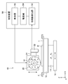
- FIG. 1 is a schematic diagram illustrating a configuration of a dicing apparatus 10 according to the first embodiment.
- the dicing apparatus 10 includes a work table 12, a ⁇ table 14, an X table 16, a blade 18, a spindle 20, a Y table (not shown), and a Z table (not shown).
- the imaging device 22 and the control device 50 are provided.
- the work table 12 holds the work W by suction.
- the workpiece W is attached to the frame F via a dicing tape ⁇ having an adhesive on the surface, and is sucked and held on the workpiece table 12.
- the frame F to which the dicing tape T is attached is held by a frame holding means (not shown) disposed on the work table 12.
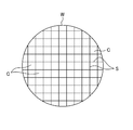
- FIG. 2 is a plan view showing the workpiece W.
- processing lines (division lines) S are formed in a lattice pattern on the surface of the workpiece W, and devices are respectively formed in a plurality of regions (device forming regions) C partitioned by these processing lines S. Is formed.
- the X table 16 is provided on the upper surface of the X base (not shown).
- the X table 16 is configured to be movable in the X direction by an X drive unit (not shown) including a motor and a ball screw.
- a ⁇ table 14 is placed on the X table 16, and a work table 12 is attached to the ⁇ table 14.
- the ⁇ table 14 is configured to be rotatable in the ⁇ direction (rotation direction about the Z axis) by a rotation drive unit (not shown) including a motor and the like.
- the Y table is provided on the side of the Y base (not shown).
- the Y table is configured to be movable in the Y direction by a Y drive unit (not shown) including a motor and a ball screw.
- a Z table (not shown) is attached to the Y table.
- the Z table is configured to be movable in the Z direction by a Z driving unit (not shown) including a motor and a ball screw.
- a high frequency motor built-in type spindle 20 with a blade 18 attached to the tip is fixed to the Z table.
- the blade 18 is indexed in the Y direction and cut and fed in the Z direction.
- the work table 12 is rotated in the ⁇ direction and cut and fed in the X direction.
- the spindle 20 is rotated at a high speed, for example, at 30,000 rpm to 60,000 rpm.
- the blade 18 is a cutting blade configured in a thin disk shape.
- an electrodeposition blade obtained by electrodepositing diamond abrasive grains or CBN (Cubic BoronrideNitride) abrasive grains with nickel, a resin blade bonded with a resin, or the like is used.
- the dimensions of the blade 18 are variously selected depending on the content of processing.
- a blade having a diameter of about 50 mm and a thickness of about 30 ⁇ m is used.
- the imaging device 22 is disposed at a position opposite to the work table 12.
- the imaging device 22 images the surface of the workpiece W in order to evaluate the alignment and processing state of the workpiece W (kerf check).
- the imaging device 22 is an example of the imaging device (alignment camera) of the present invention.
- the imaging device 22 is configured by a microscope, a camera, and the like, and images the surface of the workpiece W at a high magnification (for example, 8.0 times) or a low magnification (for example, 1.0 times) by a method such as switching a lens of the microscope. It is possible.
- An area sensor camera is used as the camera.
- the imaging device 22 is fixed to the spindle 20 via the holding member 24, and can move in the Y direction and the Z direction integrally with the spindle 20.
- the control device 50 controls the operation of each part of the dicing device 10.
- the control device 50 is realized by a general-purpose computer such as a personal computer or a microcomputer.
- the control device 50 includes a CPU (Central Processing Unit), a ROM (Read Only Memory), a RAM (Random Access Memory), a hard disk, and the like.
- various programs such as a control program stored in the ROM are expanded in the RAM, and the programs expanded in the RAM are executed by the CPU, whereby each part shown in the control device 50 in FIG. The function is realized.
- the control device 50 functions as a cutting mark detection unit 52, a storage unit 54, and a control unit 56.
- the control unit 56 controls the operation of each unit of the control device 50. Specifically, the control unit 56 controls cutting feed in the X direction of the work table 12 via the X drive unit and rotation of the work table 12 in the ⁇ direction via the ⁇ drive unit. Further, the control unit 56 controls the Y-direction index feed of the spindle 20 via the Y drive unit and the Z-direction cut feed of the spindle 20 via the Z drive unit. The control unit 56 controls the rotation operation of the spindle 20 and the imaging operation of the imaging device 22.
- the storage unit 54 stores various data necessary for the operation of the dicing apparatus 10.
- the storage unit 54 includes data on the workpiece W, data on alignment, and the thickness of the dicing tape T.
- the data relating to the workpiece W includes a product type number, material, external dimensions, thickness, chip size, and the like.
- the storage unit 54 also stores a cutting mark formation rate Q and a correction table (see FIG. 6), which will be described later.
- the cutting trace detection unit 52 receives image data captured by the imaging device 22 during dicing and detects cutting trace information to be described later by image processing or the like.
- the work W attached to the frame F via the dicing tape ⁇ is transported by a transport means (not shown) and placed on the work table 12.
- the workpiece W placed on the workpiece table 12 is imaged by the imaging device 22, and an alignment operation for performing relative alignment between the workpiece W and the blade 18 is started.
- the spindle 20 is activated and the blade 18 rotates, and cutting water and cooling water are supplied from various nozzles (not shown) provided on a wheel cover (not shown) covering the blade 18.
- the work table 12 is cut and fed in the X direction and the spindle 20 is cut and fed in the Z direction, and the work W is diced along the machining line S.
- the spindle 20 is indexed in the Y direction.
- the work table 12 is rotated 90 degrees and the work W is diced into a lattice shape.
- a cutting mark detection operation and a blade height correction operation are performed for each processing line S.
- the present invention is not limited to this, and for each processing line number specified by the user (for example, You may implement for every 5 processing lines.
- you may implement in the process line S (For example, process lines S, such as the 1st line, the 5th line, the 7th line) designated by the user.
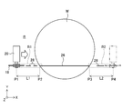
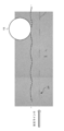
- FIG. 3 is a schematic view showing a state in which dicing processing is performed on the workpiece W.
- the blade 18 is dicing while moving relative to the workpiece W from the cutting start position P1 on one side to the cutting end position P4 on the other side with the workpiece W interposed therebetween. Processing is performed. At this time, the cutting groove 26 is formed in the workpiece W, and the cutting by the blade 18 is performed in the surface region R of the dicing tape T to which the workpiece W is not attached (hereinafter referred to as “dicing tape region R”). A mark 28 is formed.
- the blade 18 is shallowly cut. It has become. In this case, the blade 18 is not sufficiently cut into the workpiece W, which causes a cutting defect.
- the blade 18 when the cutting marks 28 in the dicing tape region R are continuously connected as a whole, the blade 18 is deeply cut. In this case, the blade 18 may become clogged due to clogging.
- the present inventor corrected the height (Z-direction position) of the blade 18 based on the cutting mark formation rate Q in the dicing tape region R in order to stabilize the processing quality.
- the cutting trace formation rate Q is the ratio of the area (length in the cutting feed direction) where the cutting trace 28 is formed in the dicing tape area R to the whole (the total length of the dicing tape area R in the cutting feed direction).
- the dicing tape region R is imaged by the imaging device 22.
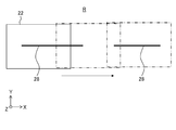
- FIG. 4 is a schematic diagram showing how the imaging device 22 images the dicing tape region R.
- the imaging device 22 images the dicing tape region R at a high magnification while shifting the position relative to the dicing tape region R in the X direction, and divides the dicing tape region R into a plurality of divided images. Capture the whole image. Image data captured by the imaging device 22 is output to the control device 50. Note that the imaging device 22 may image a wide range of the dicing tape region R at a time with a low magnification.
- an area sensor camera is used as the camera that constitutes the imaging device 22.
- the present invention is not limited to this.
- a line sensor camera may be used.
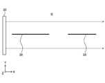
- FIG. 5 is a schematic view showing a state in which the line sensor camera 30 images the dicing tape region R.
- the line sensor camera 30 has a plurality of light receiving elements (not shown) arranged in a line in the Y direction, and images the entire dicing tape region R while scanning in the X direction. It has become.
- the cutting trace detection unit 52 detects the length of the cutting trace 28 formed in the dicing tape region R (the length in the cutting feed direction) by performing image processing on the image data captured by the imaging device 22 by a known method. To do. Further, the cutting trace detection unit 52 calculates the cutting trace formation rate Q in the dicing tape region R based on the detected length of the cutting trace 28.
- the cutting traces 28 are respectively formed in the dicing tape region R1 between the cutting start position P1 and the workpiece entry position P2, and in the dicing tape region R2 between the workpiece withdrawal position P3 and the cutting end position P4.
- the total lengths of the dicing tape regions R1 and R2 in the cutting feed direction (X direction) are L1 and L2, respectively, and the total length of the cutting marks 28 formed in the dicing tape regions R1 and R2 is l1, Let l2. For example, as shown in FIG. 3, when a plurality of cutting marks 28 are formed in the dicing tape region R1, the sum of the lengths of the respective cutting marks 28 is set to l1. The same applies to the dicing tape region R2.
- the cutting trace detection unit 52 calculates the cutting trace formation rate Q by the following formula (1).
- the cutting trace formation rate Q is stored in the storage unit 54 in association with processing line information (processing line number or the like) when the cutting trace 28 is formed.
- the unit of the cutting mark formation rate Q is%.
- the control unit 56 acquires the cutting mark formation rate Q of the reference line from the storage unit 54.
- the reference line is a processing line S in which dicing is performed immediately before the current processing line S, and the cutting trace formation rate Q has already been calculated by the above-described cutting trace detection operation.
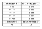
- the control unit 56 further determines a blade height correction amount G corresponding to the cutting mark formation rate Q of the reference line according to a correction table (see FIG. 6) stored in the storage unit 54. Then, the control unit 56 controls the height (Z direction position) of the blade 18 based on the determined blade height correction amount G.
- FIG. 6 is a diagram illustrating an example of the correction table.
- the correction table shows the correspondence between the cutting mark formation rate Q and the blade height correction amount G.
- This correction table also includes a target cutting mark formation rate (target formation rate) and an allowable range (target formation rate allowable range).
- target formation rate target formation rate
- allowable range target formation rate allowable range
- Each numerical value of the correction table can be appropriately set by the user via an operation unit (not shown) connected to the control device 50.
- the blade height correction amount G is a positive value
- work W becomes shallow is shown.
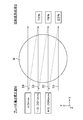
- FIG. 7 is a diagram showing a specific operation example in the present embodiment.
- the four processing lines S1 to S4 along the cutting feed direction (X direction) are diced in the order of the line numbers.
- the control unit 56 sets the blade height correction amount G to 0 and keeps the set value without correcting the height of the blade 18.
- the cutting trace detection unit 52 calculates the cutting trace formation rate (23% in this example) of the first processing line S1 based on the image data captured by the imaging device 22, and stores the calculation result in the storage unit 54.
- the control unit 56 acquires the cutting trace formation rate Q (23%) of the first processing line S1 that is the reference line from the storage unit 54. Then, the controller 56 determines the blade height correction amount G to be +0.006 mm, and controls the height of the blade 18 according to the blade height correction amount G. Further, the cutting trace detection unit 52 calculates the cutting trace formation rate (78% in this example) of the second processing line S ⁇ b> 2 based on the image data captured by the imaging device 22 and stores it in the storage unit 54.
- the control unit 56 acquires the cutting mark formation rate (78%) of the second processing line S2 that is the reference line from the storage unit 54. At this time, since the cut mark formation rate (78%) exceeds the allowable range ( ⁇ 5%) of the target ratio (70%), the control unit 56 determines the blade height correction amount G to be ⁇ 0.001 mm. Then, the height of the blade 18 is controlled according to the blade height correction amount G. In addition, the cutting trace detection unit 52 calculates the cutting trace formation rate (73% in this example) of the third processing line S3 based on the image data captured by the imaging device 22, and stores the calculation result in the storage unit 54.
- the control unit 56 acquires the cutting mark formation rate (73%) of the third processing line S3 that is the reference line from the storage unit 54. At this time, since the cut mark formation rate (73%) is within the allowable range ( ⁇ 5%) of the target ratio (70%), the control unit 56 determines the blade height correction amount G to be 0 mm, and the blade The height of the blade 18 is controlled according to the height correction amount G.
- FIG. 8 is a diagram (photograph) showing an example of an image of cutting marks.
- a plurality of cutting marks 28 are formed along the processing line S, and the cutting mark formation rate Q (Ratio in the figure) is 20%. Therefore, it can be seen that when the cutting marks 28 are formed, the lowest point in the Z direction of the blade 18 is on the + Z side of the average value of the thickness variation (unevenness) of the dicing tape T.
- the control unit 56 determines the blade height correction amount G to be +0.01 mm from the cutting mark formation rate Q (20%) of the processing line S and the correction table, and the height of the blade 18 is determined according to the blade height correction amount G. To control.
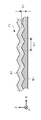
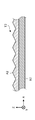
- FIG. 9 is a cross-sectional view showing a first example in which irregularities are provided on the surface of the dicing tape.
- the base material B1 of the dicing tape T1 has irregularities.
- the unevenness is periodically formed along the relative movement direction (X-axis direction) between the blade 18 and the work table 12, and extends in the Y direction.
- An adhesive layer A1 having a certain thickness is formed on the surface of the base material B1.
- the distance between the tops of the unevenness of the base material B1 (the difference in height between the tops of the peaks and the bottoms of the valleys) D1 is, for example, 5 ⁇ m to 10 ⁇ m.
- the repetition period of the unevenness in the X direction is, for example, 800 ⁇ m to 1 mm.
- the cross-sectional shape of the unevenness of the substrate B1 may be, for example, a curve (for example, a second-order or higher-order curve, a sine wave) or a triangular wave.
- a curve for example, a second-order or higher-order curve, a sine wave
- a triangular wave when the cross-sectional shape of the unevenness of the base material B1 (the shape with respect to the ZX plane) is a triangular wave, there is an advantage that the relationship between the height (cut depth) of the blade 18 and the cutting trace formation rate Q is linear. is there.
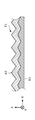
- FIG. 10 is a cross-sectional view showing a second example in which unevenness is provided on the surface of the dicing tape.
- the base material B2 of the dicing tape T2 has a constant thickness. Unevenness is periodically formed along the X-axis direction on the surface of the adhesive layer A2 formed on the surface of the base material B1.
- FIG. 11 is a cross-sectional view showing a third example in which irregularities are provided on the surface of the dicing tape.
- irregularities are periodically formed in the X-axis direction on the base material B3 of the dicing tape T3. Furthermore, irregularities are also periodically formed in the X-axis direction on the adhesive layer A3 formed on the surface of the base material B3.
- the distance between the tops of the irregularities, the repetition period in the X direction, and the cross-sectional shape in the second and third examples can be the same as in the first example.
- the dicing tapes T1 to T3 do not have to be uneven.
- unevenness may be provided so as to surround the workpiece W only in a region where the workpiece W is not attached (at least one of the cutting side and cutting-out region of the blade 18).
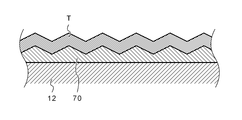
- FIG. 12 is a cross-sectional view showing a fourth example in which irregularities are provided on the surface of the dicing tape.
- the thickness of the base material and the adhesive layer of the dicing tape T are both constant.
- a plate-like member 70 is provided between the work table 12 and the dicing tape T. Unevenness is periodically formed on the surface of the plate-like member 70 along the X-axis direction.
- the distance between the apexes of the unevenness of the plate-like member 70 (the difference in height between the apex of the peak and the apex of the valley bottom) is, for example, 5 ⁇ m to 10 ⁇ m, and the repetition period of the unevenness in the X direction is, for example, 800 ⁇ m to 1 mm.
- the cross-sectional shape of the unevenness may be a curve or a triangular wave as in the first to third examples.
- the plate member 70 is a porous member having a plurality of through holes (not shown) extending in the Z direction.
- the work table 12 can adsorb and hold the dicing tape T through the through hole.
- By adsorbing the dicing tape T through the plate-like member 70 in this way it becomes possible to cause unevenness on the surface of the dicing tape T. Thereby, it can prevent that the cutting trace formation rate Q fluctuates greatly according to the fluctuation of the height of the blade 18.
- the plate-like member 70 can have a planar shape corresponding to a region where the workpiece W is not attached, for example, a shape surrounding the workpiece W.
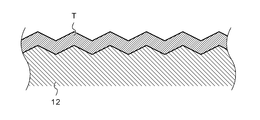
- FIG. 13 is a cross-sectional view showing a fifth example in which irregularities are provided on the surface of the dicing tape.
- the thickness of the base material and the adhesive layer of the dicing tape T are both constant.
- irregularities are periodically formed on the surface of the work table 12 along the X-axis direction.
- the distance between the apexes of the unevenness of the work table 12 (the difference in height between the apex of the peak and the apex of the valley bottom) is, for example, 5 ⁇ m to 10 ⁇ m, and the repetition period of the unevenness in the X direction is, for example, 800 ⁇ m to 1 mm.
- the cross-sectional shape of the unevenness may be a curve or a triangular wave as in the first to fourth examples.
- the surface of the dicing tape T can be made uneven by adsorbing the dicing tape T to the surface of the work table 12 provided with the unevenness. Thereby, it can prevent that the cutting trace formation rate Q fluctuates greatly according to the fluctuation of the height of the blade 18.
- the surface of the work table 12 may be provided with unevenness only in the region where the work W is not attached.
- the unevenness is formed on the surface of the work table 12.
- a suction porous on the surface of the work table 12 may be used as the concave portion.
- FIG. 14 is a diagram (photograph) showing an example in which a cutting mark is imaged.
- a solid line indicating the cross-sectional shape of the unevenness of the dicing tape T and a broken line indicating the locus of the lower end of the blade 18 are superimposed.
- a plurality of cutting traces 28 are formed along the processing line S, and the cutting trace formation rate Q is 40%. Therefore, it can be seen that when the cutting marks 28 are formed, the lowest point in the Z direction of the blade 18 is on the + Z side of the average value of the thickness variation (unevenness) of the dicing tape T.
- the control unit 56 determines the blade height correction amount G to be +0.006 mm from the cutting trace formation rate Q (40%) of the processing line S and the correction table, and the height of the blade 18 is determined according to the blade height correction amount G. To control.
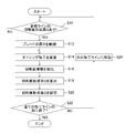
- FIG. 15 is a flowchart showing the flow of the cutting mark detection operation and the blade height correction operation of the present embodiment.
- control unit 56 checks whether or not the cutting mark formation rate Q of the reference line is stored in the storage unit 54 (step S10).
- Step S12 When the cutting trace formation rate Q of the reference line exists in the storage unit 54 (YES in step S10), the control unit 56 controls the height of the blade 18 based on the cutting trace formation rate Q of the reference line ( Step S12). Specifically, the control unit 56 refers to the correction table stored in the storage unit 54 and determines the blade height correction amount G corresponding to the cutting mark formation rate Q of the reference line. Then, the control unit 56 controls the height of the blade 18 according to the determined blade height correction amount G. Thereafter, the process proceeds to step S14.
- Step S12 is an example of a control step of the present invention.
- step S10 when the cutting mark formation rate Q of the reference line does not exist in the storage unit 54 (NO in step S10), the process proceeds to step S14.
- control unit 56 dices the workpiece W with the blade 18 that rotates at high speed while relatively moving the blade 18 and the workpiece W along the current processing line S (step S14).
- the dicing tape region R is imaged by the imaging device 22.
- the cutting trace detection unit 52 acquires image data captured by the imaging device 22 and performs image processing on the image data by a known method, thereby information on the cutting trace 28 formed in the dicing tape region R ( Cutting information) is detected (step S16).
- the cutting trace information includes at least information related to the length of the cutting trace 28 (length in the cutting feed direction).
- Step S16 is an example of the detection step of the present invention.
- the cutting trace detection unit 52 calculates the cutting trace formation rate Q in the dicing tape region R based on the detected cutting trace information (step S18).
- the calculation method of the cutting trace formation rate Q is as described above (see formula (1)).
- the cutting trace detection unit 52 stores the calculated cutting trace formation rate Q in the storage unit 54 in association with information (line information) regarding the machining line S (step S20).
- control unit 56 determines whether or not all the processing lines S have been processed (step S22). If the machining of all the machining lines S has not been completed, the process moves to the next machining line S (step S24). And the process from step S10 to step S22 is repeated until the process of all the process lines S is complete
- the blade based on the cutting trace information in the dicing tape region R (the surface region of the dicing tape T to which the workpiece W is not attached), the blade is set so that the cutting depth into the dicing tape T is constant.
- the height of 18 is controlled. Accordingly, the depth at which the blade 18 cuts into the dicing tape T can be made relatively shallow and constant without being affected by variations in the thickness of the dicing tape T, thereby stabilizing the processing quality. be able to.
- the cutting trace detection unit 52 detects the cutting trace information in the dicing tape region R based on the image data captured by the imaging device 22.
- the image pickup device 22 is constituted by an alignment camera and is originally provided in the dicing device 10, so that problems such as a complicated device configuration and an increase in cost do not occur.
- the cutting mark information is detected based on the image data captured by the imaging device 22, but the present invention is not limited thereto, and for example, a distance measuring device 32 (see FIG. 20) described later is used. It may be used to detect cutting trace information. Moreover, you may detect cutting trace information visually.
- the blade height correction amount G is determined using the cutting trace formation rate Q with the immediately preceding machining line S as a reference line.
- the adjacent processing line S means a processing line that is temporally or spatially adjacent to the current processing line S.
- the adjacent processing line S means a processing line S in the range of several lines (for example, 1 to 5 lines) in time or space from the current processing line.
- the reference line is not limited to one processing line S, and may be a plurality of processing lines S. In this case, for example, the blade height correction amount G may be determined based on the average value of the cutting trace formation rates Q corresponding to the plurality of processing lines S, respectively.
- the lengths of both the cutting marks 28 in the dicing tape region R1 on the cut side and the dicing tape region R2 on the cutout side are measured.
- the following actions can be considered.
- FIG. 16 is a schematic view showing a state in which dicing is performed on the workpiece W.
- the blade 18 is relative to the workpiece W from the cutting start position P1 (i) on one side to the cutting end position P2 (i) on the other side with the workpiece W interposed therebetween.
- the dicing process is performed while moving (i is an integer of 1 or more).
- a cutting groove 26 (i) is formed in the workpiece W, and the surface region R (hereinafter referred to as “dicing tape region R”) of the cut-out dicing tape T to which the workpiece W is not attached.
- a cutting mark 28 (i) is formed by the blade 18.
- the cutting trace 28 is formed by performing scanning control of the blade 18. Then, the height of the blade 18 is controlled according to the cut mark information.
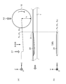
- FIG. 17 is a diagram showing a procedure for forming a cutting mark in the dicing tape region on the cut-out side.
- FIG. 17A is a side view
- FIG. 17B is a plan view (a view taken along arrow XVIIB in FIG. 17A).
- the control unit 56 (cutting trace formation control unit) moves (lowers) the blade 18 in the ⁇ Z direction as indicated by an arrow A1. Then, cut into the dicing tape T. At this time, the position of the blade 18 in the ZX direction is adjusted so as not to contact the workpiece W.
- the adjustment of the cutting depth of the blade 18 at the position of the arrow A1 may be performed manually by visually observing the surface of the dicing tape T with the imaging device 22 in real time.
- a sensor for measuring the torque applied to the spindle 20 is provided so that the control unit 56 automatically adjusts the depth when the cutting marks 28 (i) are formed according to the change in the torque. Also good.
- data relating to the relationship between the tape type (for example, material, thickness) and torque fluctuation is stored in the storage unit 54, and the control unit 56 determines the cutting depth of the blade 18 based on this data. It may be possible to determine.
- control unit 56 continuously moves the blade 18 in the direction away from the dicing tape T (+ Z direction) while relatively moving the blade 18 and the workpiece W in the X direction as indicated by an arrow A2. (Raise). At this time, the magnitude of the moving (upward) speed of the blade 18 is made smaller than the magnitude of the moving speed when the blade 18 is lowered as indicated by the arrow A1.
- the control unit 56 acquires log data regarding the relative positions of the blade 18 and the workpiece W in the ZX direction, and stores them in the storage unit 54.
- the cutting trace 28 is not formed (disconnected) as shown in FIG.
- the imaging device 22 captures an image of the cutting mark 28 is the cutting mark 28 includes a cutting trace vanishing point P E was interrupted (see FIGS. 5 to 7).
- Control unit 56 detects the cutting mark vanishing point P E from the image, the coordinates of the center of the blade 18 corresponding to the cutting marks vanishing point P E (X E, Z E ) to create a cutting mark information including, storage Store in the unit 54.
- the control unit 56 calculates the positional relationship between the lowest point in the Z direction of the blade 18 and the dicing tape T, and based on the cutting trace information when moving to the next processing line S (i). Then, the height of the blade 18 is controlled. At this time, the control unit 56 makes the cutting depth into the dicing tape T constant based on the diameter r B of the blade 18, the coordinates and thickness of the surface of the workpiece W, and the coordinates of the surface of the dicing tape T. The height of the blade 18 is controlled.
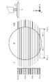
- FIG. 18 is a plan view (photograph) showing cutting marks formed in the dicing tape region R on the cut-out side.
- the cutting trace forming operation is performed in the processing lines S (j ⁇ k + 1) and S (j ⁇ (k + 1) +1), the cutting trace 28 is compared with the other processing lines. Is clearly formed. Thereby, the control part 56 can detect easily the position which the cutting trace 28 (i) interrupted from the image.
- FIG. 19 is a flowchart showing a dicing method according to the second embodiment of the present invention.
- step S30 when cutting of the first processing line S (1) is started (step S30), the control unit 56 controls the height of the blade 18 (step S32).
- step S32 for example, the height of the blade 18 is controlled based on the design value of the diameter of the blade 18 stored in the storage unit 54 or the diameter of the blade 18 calculated by the previous dicing process.
- step S34 dicing (cutting) is performed on the processing line S (1) (step S34).
- step S40 When the cutting of the processing line S (1) is completed and the blade 18 moves to the cut-out dicing tape region R, the control unit 56 performs a cutting mark forming operation (step S40).
- step S40 as shown in FIG. 17, in the dicing tape region R, the control unit 56 lowers the blade 18 and then gradually raises the cutting trace 28 while scanning in the X direction. Form.
- the control unit 56 creates log data of the coordinates of the blade 18 at each time point and stores the log data in the storage unit 54.
- Control unit 56 detects the cutting mark vanishing point P E cutting mark 28 from the image captured, it detects the cutting mark information including coordinates of the cutting marks vanishing point P E (Step S42).
- the controller 56 calculates the diameter r B of the blade 18 based on the cutting trace information (step S44).
- the diameter r B of the blade 18 is stored in the storage unit 54.
- control unit 56 starts cutting the next processing line S (2), and moves the blade 18 to the processing line S (2) (step S46).
- the control unit 56 controls the height of the blade 18 based on the diameter of the blade 18 calculated using the cutting mark information (step S48), and performs the cutting of the processing line S (2) (step S34).
- step S48 the height of the blade 18 is controlled so that the cutting depth into the dicing tape T is constant.
- steps S34 to S52 are repeated, and the machining line after S (3) is cut.
- the height of the blade 18 is controlled on the basis of the cutting mark information every j lines.
- Step S40 the process proceeds to Step S40, and the dicing tape on the cut-off side of the processing line S (i) In the region R, the cutting trace formation operation (step S40) and the cutting trace detection operation (step S42), the calculation of the diameter r B of the blade 18 based on the cutting trace information (step S44), and the next machining line S (i)
- the height control of the blade 18 during cutting is performed.
- step S44 the diameter r B of the blade 18 stored in the storage unit 54 is updated.
- step S50 the height of the blade 18 is controlled (step S52).
- the height of the blade 18 may be controlled based on the latest value of the diameter r B of the blade 18 stored in the storage unit 54.
- the cutting depth into the dicing tape T is constant based on the cutting trace information in the dicing tape region R (the surface region of the cut-out dicing tape T to which the workpiece W is not attached).
- the height of the blade 18 is controlled. Accordingly, the depth at which the blade 18 cuts into the dicing tape T can be made relatively shallow and constant without being affected by variations in the thickness of the dicing tape T, thereby stabilizing the processing quality. be able to.
- the cutting marks 28 are formed and detected in the dicing tape region R on the cut-off side, but the present invention is not limited to this.
- the cutting trace formation and detection operation may be performed in both the cut-side and cut-out side dicing tape regions, or may be performed only in the cut-side dicing tape region.
- FIG. 20 is a schematic diagram illustrating a configuration of a dicing apparatus 10A according to another embodiment.
- the same components as those in FIG. 1 are denoted by the same reference numerals, and the description thereof is omitted.
- a dicing apparatus 10A includes a distance measuring device 32 in addition to the configuration of the dicing apparatus 10 according to the present embodiment.
- the distance measuring device 32 is disposed at a position opposite to the work table 12.
- the distance measuring device 32 measures the distance to the surface of the dicing tape region R, which is a measurement object, and includes, for example, a laser displacement meter or an interference microscope.
- the measurement result of the distance measuring device 32 is output to the cutting mark detection unit 52 as distance data.
- the distance measuring device 32 is fixed to the side surface of the imaging device 22 and can move in the Y direction and the Z direction integrally with the spindle 20 and the imaging device 22.
- the distance measuring device 32 performs the cutting trace detection operation (first embodiment) or the cutting trace formation and detection operation (second embodiment) performed during dicing of the workpiece W on the dicing tape region R.
- the distance to the dicing tape region R is measured while shifting the position in the X direction.
- the distance data which is the measurement result of the distance measuring device 32, is output to the cutting mark detection unit 52.
- the cutting mark detection unit 52 generates a height graph indicating a change in height (unevenness state) in the dicing tape region R based on the distance data acquired from the distance measuring device 32.
- FIG. 21 is a diagram showing an example of a height graph generated by the cutting mark detection unit 52.
- the cutting trace detection unit 52 determines an area lower than a predetermined threshold height (height indicated by a broken line in FIG. 21) in the generated height graph as a cutting trace formation area K (cutting trace). This is detected as a region where 28 is formed. Then, the cutting trace detection unit 52 calculates the cutting trace formation rate Q based on the detected cutting trace formation region K. Subsequent processing is the same as in this embodiment.
- the cutting trace information in the dicing tape region R (the surface region of the dicing tape T to which the workpiece W is not attached) can be detected based on the measurement result of the distance measuring device 32, As with the above-described embodiment, it is possible to stabilize the processing quality.
Landscapes
- Engineering & Computer Science (AREA)
- Mechanical Engineering (AREA)
- Dicing (AREA)
- Constituent Portions Of Griding Lathes, Driving, Sensing And Control (AREA)
- Finish Polishing, Edge Sharpening, And Grinding By Specific Grinding Devices (AREA)
Abstract
ワークテーブル12にダイシングテープTを介してワークWを保持した状態で、スピンドル20により回転するブレード18とワークテーブル12とを相対移動させてダイシング加工を行うダイシング装置10であって、ワークWが貼り付けられていないダイシングテープTの表面領域に形成された切削痕情報を検出する切削痕検出部52と、切削痕検出部52が検出した切削痕情報に基づき、ダイシングテープTへの切り込み深さが一定となるようにブレード18の高さを制御する制御部56と、を備える。
Description
本発明はダイシング装置及びダイシング方法等に係り、特に、半導体装置や電子部品が形成されたウェーハ等のワークを個々のチップに分割するダイシング装置及びダイシング方法等に関する。
半導体装置や電子部品が形成されたウェーハ等のワークを個々のチップに分割するダイシング装置においては、スピンドルによって高速に回転されるブレードと、ワークを吸着保持するワークテーブルと、ワークテーブルとブレードとの相対的位置を変化させるX、Y、Z、θ駆動部とを備えている。このダイシング装置では、各駆動部によりブレードとワークとを相対的に移動させながら、ブレードによってワークを切り込むことによりダイシング加工(切削加工)する。
ダイシング装置においては、ブレードの切り込み量を設定値と一致させることは重要な要素であり、ブレードの切り込み量を設定値と一致させるにはワークへの切り込み方向であるZ軸の位置決めを繰返し高精度に行い、かつブレードの摩耗を検知して補正する必要がある。
例えば、特許文献1に記載されるように、従来はZ軸の位置決めにおいて、先ずブレードをワークテーブル上面に接触させて電気的導通を検出し、このときのブレードの中心位置を基準位置としてZ軸のコントロールを行っている。このブレードをワークテーブル上面に接触させて電気的導通を検出する動作をカッターセットという。また、ブレードの磨耗補正は、設定されたライン数ワークを加工する度にブレードとワークテーブルとを接触させ、上記基準位置を補正している。しかしながら、この方法は、ブレードをワークテーブルに接触させるので、ブレードにダメージを与えるおそれがある。
この接触式のカッターセットの問題を解決するために、例えば、特許文献2には、光学式カッターセット装置が提案されている。この光学式カッターセット装置は、投光手段と受光手段との間で光軸に直交するZ軸方向にブレードを移動させて、ブレードで徐々に検出光を遮光し、予め設定した受光量に達したときのブレード中心位置を基準としてブレードを位置決めするものである。
ところで、ブレードダイシング方式には、ハーフカット、セミフルカット、フルカットの3つの方式がある。近年では、ワークの大径化に伴い、完全にワークを切断するフルカット方式が主流となっている。フルカット方式では、ワークをダイシングテープに貼り付けた状態でワークテーブルに載置し、ブレードとワークテーブルとを相対的に移動させながら、ブレードによりワークの表面側からダイシングテープまで切り込むことにより、ワークを個々のチップに分割する。
しかしながら、上述した従来の技術では、ワークのフルカットを行うダイシングに十分に対応できていないという問題点がある。
すなわち、フルカット方式の場合には、ブレードがワークを十分に貫通し且つワークテーブルには達しないようにブレードの切り込み深さ(切り込み量)を制御する必要がある。
例えば、図22に示すように、ワークWのフルカットが行われる場合、ブレード90の高さ(ワークテーブル表面からブレード90の中心位置までの高さ)Hは、ワークWへの切り込み深さDがワークWの厚さMよりも大きくなるように位置付けられる。そして、高速回転されたブレード90に対してワークテーブル(不図示)がX方向に切削送りされることで、ワークWには1ライン分の切削溝92が形成される。
しかしながら、ダイシングテープTの厚さにばらつきが存在する場合、例えば、図23に示すように、ダイシングテープ厚さK1が図22に示したダイシングテープ厚さKに比べて薄い部分では、ワークWへの切り込み深さD1が図22に示した切り込み深さDよりも小さくなる。すなわち、ワークWに対してブレード90が浅切りとなる。この場合、ブレード90がワークWに十分に切り込んでおらず、切削不良が生じる要因となる。
一方、図24に示すように、ダイシングテープ厚さK2が図22に示したダイシングテープ厚さKに比べて厚い部分では、ワークWへの切り込み深さD2が図22に示した切り込み深さDよりも大きくなる。すなわち、ワークWに対してブレード90が深切りとなる。この場合、ブレード90がダイシングテープTに必要以上に切り込むことになる。そのため、ダイシングテープ表面の粘着剤などによりブレード90が目詰まりを起こしやすく、ブレード90の切れ味が悪くなる要因となる。
このように、ブレードが所定の高さに設定された場合であっても、ダイシングテープに厚さばらつきが存在すると、ブレードがダイシングテープに切り込む深さにばらつきが生じてしまうため、加工品質が安定しない問題が生じる可能性がある。なお、ダイシングテープの厚さばらつきに限らず、ワークテーブルの表面のうねりやブレードの摩耗などによっても同様の問題が発生する。
特に近年においては、1ウェーハ当たりのチップ数の増加に伴い、ブレードのブレード幅が薄くなる傾向にある。ブレード幅が薄くなると、それに伴ってブレードの砥粒も少なくなるので、ダイシングテープ表面の粘着剤などによりブレードが目詰まりを起こしやすく、上述した問題はより顕著なものとなる。
本発明は、このような事情に鑑みてなされたもので、ダイシングテープの厚さばらつきなどの影響を受けることなく、加工品質の安定化を図ることができるダイシング装置及びダイシング方法並びにダイシングテープを提供することを目的とする。
上記目的を達成するために、以下の発明を提供する。
本発明の第1態様に係るダイシング装置は、ワークテーブルにダイシングテープを介してワークを保持した状態で、スピンドルにより回転するブレードとワークテーブルとを相対移動させてダイシング加工を行うダイシング装置であって、ワークが貼り付けられていないダイシングテープの表面領域に形成された切削痕情報を検出する切削痕検出部と、切削痕検出部が検出した切削痕情報に基づき、ダイシングテープへの切り込み深さが一定となるようにブレードの高さを制御する制御部と、を備える。
本発明の第2態様に係るダイシング装置は、ワークテーブルにダイシングテープを介してワークを保持した状態で、スピンドルにより回転するブレードとワークテーブルとを相対移動させてダイシング加工を行うダイシング装置であって、ワークが貼り付けられておらず、かつ、ブレードとワークテーブルとの相対移動方向に沿って周期的に凹凸が設けられたダイシングテープの表面領域に形成された切削痕情報を検出する切削痕検出部と、切削痕検出部が検出した切削痕情報に基づき、ダイシングテープへの切り込み深さが一定となるようにブレードの高さを制御する制御部と、を備える。
本発明の第3態様に係るダイシング装置は、第2態様において、ワークテーブルとダイシングテープとの間に配置され、ブレードとワークテーブルとの相対移動方向に沿って周期的に凹凸が形成された板状部材を更に備え、板状部材を介してダイシングテープをワークテーブルに吸着することにより、ダイシングテープの表面領域に凹凸が形成されるようにしたものである。
本発明の第4態様に係るダイシング装置は、第2態様において、ワークテーブルの表面には、ブレードとワークテーブルとの相対移動方向に沿って周期的に凹凸が形成されており、ダイシングテープをワークテーブルに吸着することにより、ダイシングテープの表面領域に凹凸が形成されるようにしたものである。
本発明の第5態様は、第2態様のダイシング装置に用いられるダイシングテープであって、ダイシングテープの基材及び接着剤層の少なくとも一方に設けられた凹凸を有し、凹凸によりダイシングテープの表面領域の凹凸が構成されたものである。
本発明の第6態様に係るダイシング装置は、第1態様から第5態様のいずれかにおいて、切削痕検出部は、切削痕情報に基づいてダイシングテープの表面領域における切削痕形成率を算出し、制御部は、切削痕検出部が算出した切削痕形成率に基づいて、切削痕形成率が一定の範囲内となるようにブレードの高さを制御する。
本発明の第7の態様に係るダイシング装置は、ワークテーブルにダイシングテープを介してワークを保持した状態で、スピンドルにより回転するブレードとワークテーブルとを相対移動させてダイシング加工を行うダイシング装置であって、ワークが貼り付けられていないダイシングテープの表面領域において切削痕を形成する切削痕形成制御部であって、ブレードとワークテーブルとの相対移動に伴ってブレードをダイシングテープから離れる方向に移動させて切削痕消失点を形成する切削痕形成制御部と、切削痕消失点の位置に関する情報を含む切削痕情報を検出する切削痕検出部と、切削痕検出部が検出した切削痕情報に基づき、ダイシングテープへの切り込み深さが一定となるようにブレードの高さを制御する制御部とを備える。
本発明の第8態様に係るダイシング装置は、第1態様から第7態様のいずれかにおいて、ワークテーブルの対向位置に配置された撮像装置を備え、切削痕検出部は、撮像装置で撮像されたダイシングテープの表面領域の画像データに基づいて切削痕情報を検出する。
本発明の第9態様に係るダイシング装置は、第8態様において、撮像装置はアライメント用カメラで構成される。
本発明の第10態様に係るダイシング装置は、第1態様から第7態様のいずれかにおいて、ワークテーブルの対向位置に配置された距離測定装置を備え、切削痕検出部は、距離測定装置で測定されたダイシングテープの表面領域までの距離を示す距離データに基づいて切削痕情報を検出する。
本発明の第12態様に係るダイシング方法は、ワークテーブルにダイシングテープを介してワークを保持した状態で、スピンドルにより回転するブレードとワークテーブルとを相対移動させてダイシング加工を行うダイシング方法であって、ワークが貼り付けられていないダイシングテープの表面領域に形成された切削痕情報を検出する検出ステップと、検出ステップで検出した切削痕情報に基づき、ダイシングテープへの切り込み深さが一定となるようにブレードの高さを制御する制御ステップと、を備える。
本発明の第13態様に係るダイシング方法は、ワークテーブルにダイシングテープを介してワークを保持した状態で、スピンドルにより回転するブレードとワークテーブルとを相対移動させてダイシング加工を行うダイシング方法であって、ワークが貼り付けられておらず、かつ、ブレードとワークテーブルとの相対移動方向に沿って周期的に凹凸が設けられたダイシングテープの表面領域に形成された切削痕情報を検出する検出ステップと、検出ステップで検出した切削痕情報に基づき、ダイシングテープへの切り込み深さが一定となるようにブレードの高さを制御する制御ステップと、を備える。
本発明の第14態様に係るダイシング方法は、第13態様において、ダイシングテープの基材及び接着剤層の少なくとも一方に凹凸を設けることにより、ダイシングテープの表面領域に凹凸を形成するようにしたものである。
本発明の第15態様に係るダイシング方法は、第13態様において、ブレードとワークテーブルとの相対移動方向に沿って周期的に凹凸が形成された板状部材を、ワークテーブルとダイシングテープとの間に配置し、板状部材を介してダイシングテープをワークテーブルに吸着することにより、ダイシングテープの表面領域に凹凸を形成するようにしたものである。
本発明の第16態様に係るダイシング方法は、第13態様において、ワークテーブルの表面には、ブレードとワークテーブルとの相対移動方向に沿って周期的に凹凸が形成されており、ダイシングテープをワークテーブルに吸着することにより、ダイシングテープの表面領域に凹凸を形成するようにしたものである。
本発明の第17の態様に係るダイシング方法は、ワークテーブルにダイシングテープを介してワークを保持した状態で、スピンドルにより回転するブレードとワークテーブルとを相対移動させてダイシング加工を行うダイシング方法であって、ワークが貼り付けられていないダイシングテープの表面領域において切削痕を形成するステップであって、ブレードとワークテーブルとの相対移動に伴ってブレードをダイシングテープから離れる方向に移動させて切削痕消失点を形成する形成ステップと、切削痕消失点の位置に関する情報を含む切削痕情報を検出する検出ステップと、切削痕情報からブレードの径を算出し、ブレードの径に基づき、ダイシングテープへの切り込み深さが一定となるようにブレードの高さを制御する制御ステップとを備える。
本発明の第18の態様に係るダイシング方法は、第17態様において、切削痕を形成する際の各時点におけるブレードの位置に関するログデータを記憶するステップを更に備え、検出ステップにおいて、切削痕消失点の位置に関する情報をログデータから取得するようにしたものである。
本発明の第19の態様に係るダイシング方法は、第17態様又は第18態様の形成ステップにおいて、ワークの切り抜け側のダイシングテープ領域に切削痕を形成するようにしたものである。
本発明の第20の態様に係るダイシング方法は、第17態様から第19態様のいずれかにおいて、形成ステップ及び検出ステップが、少なくとも1の加工ラインおきに行われるようにしたものである。
本発明によれば、ダイシングテープの厚さばらつきなどの影響を受けることなく、加工品質の安定化を図ることができる。
以下、添付図面に従って本発明の実施形態について説明する。
〈第1の実施形態〉
[ダイシング装置10の構成]
図1は、第1の実施形態に係るダイシング装置10の構成を示した概略図である。
[ダイシング装置10の構成]
図1は、第1の実施形態に係るダイシング装置10の構成を示した概略図である。
図1に示すように、ダイシング装置10は、ワークテーブル12と、θテーブル14と、Xテーブル16と、ブレード18と、スピンドル20と、Yテーブル(不図示)と、Zテーブル(不図示)と、撮像装置22と、制御装置50とを備えている。
ワークテーブル12は、ワークWを吸着保持する。ワークWは、表面に粘着剤を有するダイシングテープТを介してフレームFに貼着され、ワークテーブル12に吸着保持される。なお、ダイシングテープTが貼着されたフレームFは、ワークテーブル12に配設されたフレーム保持手段(不図示)に保持される。
図2は、ワークWを示した平面図である。図2に示すように、ワークWの表面には、加工ライン(分割予定ライン)Sが格子状に形成され、これらの加工ラインSによって区画された複数の領域(デバイス形成領域)Cにそれぞれデバイスが形成されている。
図1に戻り、Xテーブル16は、図示しないXベースの上面に設けられている。Xテーブル16は、モータ及びボールねじ等を含むX駆動部(不図示)によりX方向に移動可能に構成される。Xテーブル16にはθテーブル14が載置され、θテーブル14にはワークテーブル12が取り付けられている。θテーブル14は、モータ等を含む回転駆動部(不図示)によりθ方向(Z軸を中心とする回転方向)に回転可能に構成される。
Yテーブルは、図示しないYベースの側面に設けられている。Yテーブルは、モータ及びボールねじ等を含むY駆動部(不図示)によりY方向に移動可能に構成される。Yテーブルには、Zテーブル(不図示)が取り付けられている。Zテーブルは、モータ及びボールねじ等を含むZ駆動部(不図示)によりZ方向に移動可能に構成される。Zテーブルには、先端にブレード18が取り付けられた高周波モータ内蔵型のスピンドル20が固定されている。
かかる構成により、ブレード18は、Y方向にインデックス送りされるとともにZ方向に切り込み送りされる。また、ワークテーブル12は、θ方向に回転されるとともにX方向に切削送りされる。
スピンドル20は、例えば30,000rpm~60,000rpmで高速回転される。
ブレード18は、薄い円盤状に構成された切削刃である。ブレード18としては、ダイヤモンド砥粒やCBN(Cubic Boron Nitride)砥粒をニッケルで電着した電着ブレードや、樹脂で結合したレジンブレード等が用いられる。また、ブレード18の寸法は、加工内容によって種々選択されるが、通常の半導体ウェーハをワークWとしてダイシングする場合は直径50mm、厚さ30μm前後のものが用いられる。
撮像装置22は、ワークテーブル12の対向位置に配置される。撮像装置22は、ワークWのアライメントや加工状態を評価(カーフチェック)するために、ワークWの表面を撮像するものである。なお、撮像装置22は、本発明の撮像装置(アライメント用カメラ)の一例である。
撮像装置22は、顕微鏡やカメラ等により構成され、顕微鏡のレンズを切り替えるなどの方法により、ワークWの表面を高倍率(例えば8.0倍)または低倍率(例えば1.0倍)により撮像することが可能である。カメラとしては、エリアセンサカメラが用いられる。
撮像装置22は、保持部材24を介してスピンドル20に固定されており、スピンドル20と一体となってY方向及びZ方向に移動可能となっている。
制御装置50は、ダイシング装置10の各部の動作を制御する。制御装置50は、例えばパーソナルコンピュータやマイクロコンピュータなどの汎用のコンピュータによって実現されるものである。
制御装置50は、CPU(Central Processing Unit)、ROM(Read Only Memory)、RAM(Random Access Memory)、ハードディスク等を備えている。制御装置50では、ROMに記憶されている制御プログラム等の各種プログラムがRAMに展開され、RAMに展開されたプログラムがCPUによって実行されることにより、図1において制御装置50内に示した各部の機能が実現されるものである。
制御装置50は、切削痕検出部52と、記憶部54と、制御部56として機能する。
制御部56は、制御装置50の各部の動作を制御する。具体的には、制御部56は、X駆動部を介してワークテーブル12のX方向の切削送りや、θ駆動部を介してワークテーブル12のθ方向の回転を制御する。また、制御部56は、Y駆動部を介してスピンドル20のY方向のインデックス送りや、Z駆動部を介してスピンドル20のZ方向の切り込み送りを制御する。また、制御部56は、スピンドル20の回転動作や、撮像装置22の撮像動作を制御する。
記憶部54は、ダイシング装置10の動作に必要な各種データを記憶する。記憶部54には、ワークWに関するデータや、アライメントに関するデータ及びダイシングテープTの厚さも含まれる。例えば、ワークWに関するデータとしては、品種番号、材質、外形寸法、厚さ、チップサイズ等がある。また、記憶部54には、後述する切削痕形成率Qや補正テーブル(図6参照)なども記憶される。
切削痕検出部52は、ダイシング加工中に撮像装置22が撮像した画像データを受けて、画像処理等によって後述する切削痕情報を検出するものである。
[ダイシング装置10の作用]
次に、このように構成されたダイシング装置10の作用について説明する。
次に、このように構成されたダイシング装置10の作用について説明する。
まず、ダイシングテープТを介してフレームFに貼着されたワークWが、不図示の搬送手段によって搬送されてワークテーブル12に載置される。ワークテーブル12上に載置されたワークWは撮像装置22により撮像され、ワークWとブレード18との相対的な位置合わせを行うアライメント動作を開始する。
アライメント動作が終了すると、スピンドル20が起動してブレード18が回転するとともに、ブレード18を覆うホイールカバー(不図示)に備えられた各種ノズル(不図示)より切削水や冷却水が供給される。この状態でワークテーブル12がX方向に切削送りされるとともにスピンドル20がZ方向に切り込み送りされてワークWが加工ラインSに沿ってダイシング加工される。1ライン加工する毎にスピンドル20はY方向にインデックス送りされ、一方向の加工が終了するとワークテーブル12が90度回転してワークWは格子状にダイシング加工される。
本実施形態では、ワークWのダイシング加工中には、加工ラインS毎に、後述する切削痕検出動作及びブレード高さ補正動作が行われる。
なお、本実施形態では、加工ラインS毎に、後述する切削痕検出動作及びブレード高さ補正動作が行われるようにしたが、これに限らず、ユーザにより指定された加工ライン数毎(例えば、加工ライン5本毎)に実施してもよい。また、ユーザにより指定された加工ラインS(例えば、1ライン目、5ライン目、7ライン目などの加工ラインS)で実施してもよい。
(切削痕検出動作)
次に、切削痕検出動作について説明する。
次に、切削痕検出動作について説明する。
図3は、ワークWに対してダイシング加工が行われる様子を示した概略図である。
本実施形態においては、図3に示すように、ブレード18が、ワークWを挟んで一方側の切削開始位置P1から他方側の切削終了位置P4までワークWに対して相対的に移動しながらダイシング加工が行われる。このとき、ワークWには切削溝26が形成されるとともに、ワークWが貼り付けられていないダイシングテープTの表面領域R(以下、「ダイシングテープ領域R」という。)には、ブレード18による切削痕28が形成される。
例えば、ダイシングテープ領域Rにおける切削痕28が全体的に短く細切れ状になっているような場合(図3参照)、あるいは、切削痕28がまったく存在しないような場合には、ブレード18が浅切りとなっている。この場合、ブレード18がワークWに十分に切り込んでおらず、切削不良が生じる要因となる。
一方、ダイシングテープ領域Rにおける切削痕28が全体的に長くつながっているような場合には、ブレード18が深切りとなっている。この場合、ブレード18の目詰まりにより切れ味が悪くなる可能性がある。
本発明者は、検討を重ねた結果、加工品質の安定化を図るためには、ダイシングテープ領域Rにおける切削痕形成率Qに基づいて、ブレード18の高さ(Z方向位置)を補正すればよいことを見出した。ここで、切削痕形成率Qとは、ダイシングテープ領域Rにおいて切削痕28が形成された領域(切削送り方向の長さ)が全体(ダイシングテープ領域Rの切削送り方向の全長さ)に占める割合をいう。
本実施形態における切削痕検出動作では、ダイシングテープ領域Rを撮像装置22により撮像して行われる。
図4は、撮像装置22がダイシングテープ領域Rを撮像する様子を示した概略図である。図4に示すように、撮像装置22は、ダイシングテープ領域Rに対する位置をX方向にずらしながら、ダイシングテープ領域Rを高倍率により複数個所撮像し、ダイシングテープ領域Rを複数の分割画像に分けて全体を撮像する。撮像装置22が撮像した画像データは制御装置50に出力される。なお、撮像装置22は、低倍率によりダイシングテープ領域Rの広い範囲を一度に撮像してもよい。
なお、本実施形態では、撮像装置22を構成するカメラとして、エリアセンサカメラが用いられているが、これに限らず、例えばラインセンサカメラが用いられてもよい。
図5は、ラインセンサカメラ30がダイシングテープ領域Rを撮像する様子を示した概略図である。図5に示すように、ラインセンサカメラ30は、Y方向に複数の受光素子(不図示)が1列に並べられており、X方向にスキャンしながら、ダイシングテープ領域R全体を撮像するようになっている。
切削痕検出部52は、撮像装置22が撮像した画像データに既知の手法により画像処理することで、ダイシングテープ領域Rに形成された切削痕28の長さ(切削送り方向の長さ)を検出する。また、切削痕検出部52は、検出した切削痕28の長さに基づいて、ダイシングテープ領域Rにおける切削痕形成率Qを算出する。
ここで、ダイシングテープ領域Rにおける切削痕形成率Qの算出方法について説明する。
図3において、ブレード18が切削開始位置P1から切削終了位置P4までワークWに対して相対移動する際、ブレード18がワークWへの切り込みを開始する位置をワーク進入位置P2とし、ブレード18がワークWへの切り込みを終了する位置をワーク退出位置P3とする。
このとき、切削痕28は、切削開始位置P1とワーク進入位置P2との間のダイシングテープ領域R1、およびワーク退出位置P3と切削終了位置P4との間のダイシングテープ領域R2にそれぞれ形成される。
また、各ダイシングテープ領域R1、R2の切削送り方向(X方向)の全長さをそれぞれL1、L2とし、各ダイシングテープ領域R1、R2にそれぞれ形成された切削痕28の長さの総和をl1、l2とする。例えば、図3に示すように、ダイシングテープ領域R1に複数の切削痕28が形成される場合には、各切削痕28の長さの総和をl1とする。ダイシングテープ領域R2についても同様である。
切削痕検出部52は、以下の式(1)によって切削痕形成率Qを算出する。この切削痕形成率Qは、切削痕28が形成されたときの加工ライン情報(加工ライン番号等)と関連付けて記憶部54に記憶される。なお、切削痕形成率Qの単位は%である。
Q={(l1+l2)/(L1+L2)}×100 ・・・(1)
(ブレード高さ補正動作)
次に、ブレード高さ補正動作について説明する。
(ブレード高さ補正動作)
次に、ブレード高さ補正動作について説明する。
ブレード高さ補正動作では、制御部56は、記憶部54から参照ラインの切削痕形成率Qを取得する。参照ラインは、現在の加工ラインSの直前にダイシング加工が行われた加工ラインSであり、上述した切削痕検出動作により切削痕形成率Qが既に算出されたものである。
制御部56はさらに、記憶部54に記憶された補正テーブル(図6参照)に従って、参照ラインの切削痕形成率Qに対応したブレード高さ補正量Gを決定する。そして、制御部56は、決定したブレード高さ補正量Gに基づいてブレード18の高さ(Z方向位置)を制御する。
(補正テーブル)
図6は、補正テーブルの一例を示した図である。図6に示すように、補正テーブルは、切削痕形成率Qとブレード高さ補正量Gとの対応関係を示したものである。この補正テーブルには、目標とする切削痕形成率(目標形成率)とその許容範囲(目標形成率許容範囲)も含まれている。なお、補正テーブルの各数値は、制御装置50に接続される操作部(不図示)を介してユーザが適宜設定可能となっている。また、ブレード高さ補正量Gは、正の値である場合には設定値からワークWへの切り込み深さが深くなる方向への補正を示しており、負の値である場合には設定値からワークWへの切り込み深さが浅くなる方向への補正を示している。
図6は、補正テーブルの一例を示した図である。図6に示すように、補正テーブルは、切削痕形成率Qとブレード高さ補正量Gとの対応関係を示したものである。この補正テーブルには、目標とする切削痕形成率(目標形成率)とその許容範囲(目標形成率許容範囲)も含まれている。なお、補正テーブルの各数値は、制御装置50に接続される操作部(不図示)を介してユーザが適宜設定可能となっている。また、ブレード高さ補正量Gは、正の値である場合には設定値からワークWへの切り込み深さが深くなる方向への補正を示しており、負の値である場合には設定値からワークWへの切り込み深さが浅くなる方向への補正を示している。
(具体的な動作例)
図7は、本実施形態における具体的な動作例を示した図である。なお、ここでは、説明を簡略化するため、切削送り方向(X方向)に沿った4つの加工ラインS1~S4をライン番号順にダイシング加工を行う場合について説明する。
図7は、本実施形態における具体的な動作例を示した図である。なお、ここでは、説明を簡略化するため、切削送り方向(X方向)に沿った4つの加工ラインS1~S4をライン番号順にダイシング加工を行う場合について説明する。
図7に示すように、まず、第1加工ラインS1に対してダイシング加工が行われる。この場合、参照ラインが存在しないため、制御部56は、ブレード高さ補正量Gを0とし、ブレード18の高さを補正せずに設定値のままとする。また、切削痕検出部52は、撮像装置22が撮像した画像データに基づいて第1加工ラインS1の切削痕形成率(本例では23%)を算出して、記憶部54に記憶する。
次に、第2加工ラインS2に対してダイシング処理が行われる。この場合、制御部56は、参照ラインである第1加工ラインS1の切削痕形成率Q(23%)を記憶部54から取得する。そして、制御部56は、ブレード高さ補正量Gを+0.006mmに決定し、そのブレード高さ補正量Gに従ってブレード18の高さを制御する。また、切削痕検出部52は、撮像装置22が撮像した画像データに基づいて第2加工ラインS2の切削痕形成率(本例では78%)を算出して、記憶部54に記憶する。
次に、第3加工ラインS3に対してダイシング加工が行われる.この場合、制御部56は、参照ラインである第2加工ラインS2の切削痕形成率(78%)を記憶部54から取得する。このとき、切削痕形成率(78%)が目標割合(70%)の許容範囲(±5%)を超えているため、制御部56は、ブレード高さ補正量Gを-0.001mmと決定し、そのブレード高さ補正量Gに従ってブレード18の高さを制御する。また、切削痕検出部52は、撮像装置22が撮像した画像データに基づいて第3加工ラインS3の切削痕形成率(本例では73%)を算出して、記憶部54に記憶する。
次に、第4加工ラインS4に対してダイシング加工が行われる。この場合、制御部56は、参照ラインである第3加工ラインS3の切削痕形成率(73%)を記憶部54から取得する。このとき、切削痕形成率(73%)が目標割合(70%)の許容範囲(±5%)内であるため、制御部56は、ブレード高さ補正量Gを0mmと決定し、そのブレード高さ補正量Gに従ってブレード18の高さを制御する。
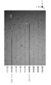
次に、切削痕28の具体例について、図8を参照して説明する。図8は、切削痕を撮像した例を示す図(写真)である。
図8に示す例では、加工ラインSに沿って切削痕28が複数形成されており、切削痕形成率Q(図中のRatio)は20%である。よって、切削痕28の形成時に、ブレード18のZ方向の最下点が、ダイシングテープTの厚さばらつき(凹凸)の高さの平均値より+Z側であったことがわかる。
制御部56は、加工ラインSの切削痕形成率Q(20%)と補正テーブルから、ブレード高さ補正量Gを+0.01mmに決定し、そのブレード高さ補正量Gに従ってブレード18の高さを制御する。
(ダイシングテープの厚さばらつき)
ところで、ダイシングテープTの厚さばらつき(凹凸)が小さい場合と比べて、ダイシングテープTの厚さばらつき(凹凸)が大きい場合には、ブレード18の高さの変動が微小であっても、この変動を切削痕形成率Qの変化として捉えることが可能になる。このため、ダイシングテープTの厚さばらつき(凹凸)を大きくすれば、ブレード18の高さ調整の精度を向上させることができる。
ところで、ダイシングテープTの厚さばらつき(凹凸)が小さい場合と比べて、ダイシングテープTの厚さばらつき(凹凸)が大きい場合には、ブレード18の高さの変動が微小であっても、この変動を切削痕形成率Qの変化として捉えることが可能になる。このため、ダイシングテープTの厚さばらつき(凹凸)を大きくすれば、ブレード18の高さ調整の精度を向上させることができる。
そこで、以下の例では、ダイシングテープTの表面に凹凸を設けることにより、ブレード18の高さの変動に応じた切削痕形成率Qの変動を調整する例について説明する。ダイシングテープTの表面に凹凸を設けた例としては、例えば、下記のようなものが考えられる。
図9は、ダイシングテープの表面に凹凸を設けた第1の例を示す断面図である。
図9に示す例では、ダイシングテープT1の基材B1には凹凸が形成されている。この凹凸は、ブレード18とワークテーブル12との相対移動方向(X軸方向)に沿って周期的に形成されており、Y方向に伸びている。基材B1の表面に、一定の厚さの接着剤層A1が形成されている。
基材B1の凹凸の頂点間の距離(山の頂点と谷底の頂点の高さの差)D1は、一例で5μmから10μmである。また、凹凸のX方向の繰り返し周期は一例で800μmから1mmである。
基材B1の凹凸の断面形状(ZX平面に対する形状)は、例えば、曲線(例えば、2次又は高次の曲線、正弦波)であってもよいし、三角波であってもよい。なお、基材B1の凹凸の断面形状(ZX平面に対する形状)を三角波とした場合には、ブレード18の高さ(切り込み深さ)と切削痕形成率Qとの関係が線形になるという利点がある。
図9に示す例によれば、ダイシングテープTの表面に凹凸を設けることにより、ブレード18の高さの変動に応じて切削痕形成率Qが大きく変動することを防止することができるので、ブレード18の高さ調整の精度を確保することができる。
図10は、ダイシングテープの表面に凹凸を設けた第2の例を示す断面図である。
図10に示す例では、ダイシングテープT2の基材B2は厚さが一定である。そして、基材B1の表面に形成された接着剤層A2の表面に、X軸方向に沿って周期的に凹凸が形成されている。
図11は、ダイシングテープの表面に凹凸を設けた第3の例を示す断面図である。
図11に示す例では、ダイシングテープT3の基材B3に、X軸方向に周期的に凹凸が形成されている。さらに、基材B3の表面に形成された接着剤層A3にもX軸方向に周期的に凹凸が形成されている。
なお、第2及び第3の例における凹凸の頂点間の距離、X方向の繰り返し周期及び断面形状は、第1の例と同様にすることが可能である。
また、第1から第3の例では、ダイシングテープT1~T3の全面に凹凸を設けなくてもよい。例えば、ダイシングテープT1~T3のうち、ワークWが貼り付けられない領域(ブレード18の切り込み側及び切り抜け側の領域の少なくとも一方)のみに、ワークWを取り囲むように凹凸を設けてもよい。
図12は、ダイシングテープの表面に凹凸を設けた第4の例を示す断面図である。
図12に示す例では、ダイシングテープTの基材及び接着剤層の厚さはいずれも一定である。
図12に示す例では、ワークテーブル12とダイシングテープTとの間に、板状部材70が設けられている。板状部材70の表面には、X軸方向に沿って周期的に凹凸が形成されている。板状部材70の凹凸の頂点間の距離(山の頂点と谷底の頂点の高さの差)は、一例で5μmから10μmであり、凹凸のX方向の繰り返し周期は一例で800μmから1mmである。また、凹凸の断面形状は、第1から第3の例と同様に、曲線であってもよいし、三角波であってもよい。
板状部材70は、Z方向に伸びる不図示の複数の貫通孔を有する多孔質(ポーラス)部材である。ワークテーブル12は、この貫通孔を介してダイシングテープTを吸着して保持することが可能となっている。このように板状部材70を介してダイシングテープTを吸着することにより、ダイシングテープTの表面に凹凸を生じさせることが可能になる。これにより、ブレード18の高さの変動に応じて切削痕形成率Qが大きく変動することを防止することができる。
なお、図12に示す例では、板状部材70は、ワークWが貼り付けられない領域に応じた平面形状、例えば、ワークWを取り囲む形状とすることができる。
図13は、ダイシングテープの表面に凹凸を設けた第5の例を示す断面図である。
図13に示す例では、ダイシングテープTの基材及び接着剤層の厚さはいずれも一定である。
図13に示す例では、ワークテーブル12の表面には、X軸方向に沿って周期的に凹凸が形成されている。ワークテーブル12の凹凸の頂点間の距離(山の頂点と谷底の頂点の高さの差)は、一例で5μmから10μmであり、凹凸のX方向の繰り返し周期は一例で800μmから1mmである。また、凹凸の断面形状は、第1から第4の例と同様に、曲線であってもよいし、三角波であってもよい。
図13に示す例では、凹凸が表面に設けられたワークテーブル12の表面にダイシングテープTを吸着することにより、ダイシングテープTの表面に凹凸を生じさせることが可能になる。これにより、ブレード18の高さの変動に応じて切削痕形成率Qが大きく変動することを防止することができる。
なお、図13に示す例では、ワークテーブル12の表面のうちワークWが貼り付けられない領域のみに凹凸を設けてもよい。また、図13に示す例では、ワークテーブル12の表面に凹凸を形成したが、例えば、ワークテーブル12の表面の吸着用のポーラスを凹部として利用するようにしてもよい。
(切削痕の具体例)
次に、切削痕28の具体例について、図14を参照して説明する。図14は、切削痕を撮像した例を示す図(写真)である。図14には、ダイシングテープTの凹凸の断面形状を示す実線及びブレード18の下端部の軌跡を示す破線が重畳して示されている。
次に、切削痕28の具体例について、図14を参照して説明する。図14は、切削痕を撮像した例を示す図(写真)である。図14には、ダイシングテープTの凹凸の断面形状を示す実線及びブレード18の下端部の軌跡を示す破線が重畳して示されている。
図14に示す例では、加工ラインSに沿って切削痕28が複数形成されており、切削痕形成率Qは40%である。よって、切削痕28の形成時に、ブレード18のZ方向の最下点が、ダイシングテープTの厚さばらつき(凹凸)の高さの平均値より+Z側であったことがわかる。
制御部56は、加工ラインSの切削痕形成率Q(40%)と補正テーブルから、ブレード高さ補正量Gを+0.006mmに決定し、そのブレード高さ補正量Gに従ってブレード18の高さを制御する。
図9から図14に示す例では、ダイシングテープTの表面に凹凸を設けることにより、ダイシングテープの厚さばらつきなどの影響を受けることなく、加工品質の安定化を図ることができる。
(フローチャート)
図15は、本実施形態の切削痕検出動作及びブレード高さ補正動作の流れを示したフローチャートである。
図15は、本実施形態の切削痕検出動作及びブレード高さ補正動作の流れを示したフローチャートである。
まず、ワークWに対してダイシング加工を行う場合、制御部56は、参照ラインの切削痕形成率Qが記憶部54に記憶されているか否かを確認する(ステップS10)。
参照ラインの切削痕形成率Qが記憶部54に存在する場合には(ステップS10においてYES)、制御部56は、参照ラインの切削痕形成率Qに基づいてブレード18の高さを制御する(ステップS12)。具体的には、制御部56は、記憶部54に記憶された補正テーブルを参照して、参照ラインの切削痕形成率Qに対応したブレード高さ補正量Gを決定する。そして、制御部56は、決定したブレード高さ補正量Gに従ってブレード18の高さを制御する。その後、ステップS14に進む。ステップS12は、本発明の制御ステップの一例である。
一方、参照ラインの切削痕形成率Qが記憶部54に存在しない場合には(ステップS10においてNO)、ステップS14に進む。
次に、制御部56は、現在の加工ラインSに沿ってブレード18とワークWとを相対移動させながら、高速回転するブレード18でワークWをダイシング加工する(ステップS14)。
次に、撮像装置22によってダイシングテープ領域Rが撮像される。そして、切削痕検出部52は、撮像装置22が撮像した画像データを取得し、その画像データに公知の手法で画像処理を施すことにより、ダイシングテープ領域Rに形成された切削痕28に関する情報(切削痕情報)を検出する(ステップS16)。なお、切削痕情報には、少なくとも切削痕28の長さ(切削送り方向の長さ)に関する情報が含まれる。ステップS16は、本発明の検出ステップの一例である。
次に、切削痕検出部52は、検出した切削痕情報に基づいて、ダイシングテープ領域Rにおける切削痕形成率Qを算出する(ステップS18)。切削痕形成率Qの算出方法は、上述したとおりである(式(1)を参照)。
次に、切削痕検出部52は、算出した切削痕形成率Qを加工ラインSに関する情報(ライン情報)と関連付けて記憶部54に記憶する(ステップS20)。
次に、制御部56は、全ての加工ラインSの加工が終了したか否かを判断する(ステップS22)。全ての加工ラインSの加工が終了していない場合には、次の加工ラインSに移動する(ステップS24)。そして、全ての加工ラインSの加工が終了するまで、ステップS10からステップS22までの処理を繰り返す。
[本実施形態の作用効果]
次に、本実施形態の作用効果について説明する。
次に、本実施形態の作用効果について説明する。
本実施形態によれば、ダイシングテープ領域R(ワークWが貼り付けられていないダイシングテープTの表面領域)における切削痕情報に基づいて、ダイシングテープTへの切り込み深さが一定となるようにブレード18の高さが制御される。これにより、ダイシングテープTの厚さばらつきなどの影響を受けることなく、ブレード18がダイシングテープTに切り込む深さを比較的浅くかつ一定にすることが可能となるので、加工品質の安定化を図ることができる。
また、本実施形態によれば、切削痕検出部52は、撮像装置22が撮像した画像データに基づいて、ダイシングテープ領域Rにおける切削痕情報を検出するようになっている。この撮像装置22はアライメント用カメラで構成され、ダイシング装置10にもともと具備されているものであり、これによる装置構成の複雑化やコストの増大という問題は起こらない。
なお、本実施形態においては、撮像装置22が撮像した画像データに基づいて切削痕情報を検出するように構成したが、これに限らず、例えば、後述する距離測定装置32(図20参照)を用いて切削痕情報を検出してもよい。また、目視で切削痕情報を検出してもよい。
また、加工ライン数(例えば2067ライン)が多い場合、全ての加工ラインSのダイシング加工が完了するまでのブレード摩耗量は無視できない。そのため、従来は、ダイシング加工中に何度もカッターセットを実施して現在のブレード摩耗量を計測し、ブレード18の高さを調整する必要があった。これに対し、本実施形態では、ワークWのダイシング加工中において、加工ラインS毎に、切削痕検出動作が行われる。そのため、現在のブレード摩耗量をリアルタイムで把握できるため、従来のようなブレード摩耗量の計測動作を頻繁に行うことが不要となり、ダイシング加工が完了するまでの時間を減らすことができるというメリットがある。
また、本実施形態では、現在の加工ラインSに対してダイシング加工する際に、直前の加工ラインSを参照ラインとして、その切削痕形成率Qを用いてブレード高さ補正量Gを決定するようにしたが、これに限らず、現在の加工ラインSに時間的または空間的に隣接又は近接した加工ラインSを参照ラインとしてもよい。なお、隣接した加工ラインSとは、現在の加工ラインSと時間的または空間的に隣り合った加工ラインであることを意味する。また、近接した加工ラインSとは、現在の加工ラインから時間的または空間的に数ライン(例えば1~5ライン)の範囲にある加工ラインSを意味する。また、参照ラインは1つの加工ラインSに限らず、複数の加工ラインSであってもよい。この場合、例えば、複数の加工ラインSにそれぞれ対応する切削痕形成率Qの平均値に基づいてブレード高さ補正量Gを決定してもよい。
また、本実施形態では、ブレード18の高さが安定するまでの間にダイシング加工した加工ラインS(最初の1~3ライン)の切削品質が悪くなってしまう可能性がある。この問題は、実際にダイシング加工を開始する前にダイシングテープT上で空切りを何度か行って、予めブレード18の高さを調整した上でダイシング加工を行うことにより解決することができる。
また、本実施形態では、切削痕検出動作において、切り込み側となるダイシングテープ領域R1と、切り抜け側となるダイシングテープ領域R2との両方の切削痕28の長さを計測しているが、切削条件によっては以下のような動作も考えらえる。
(切削の負荷が高いワークの場合)
ダイシング加工中にブレード18がより摩耗するため、切り抜け側となるダイシングテープ領域R2に存在する切削痕28の長さのみを計測する。ダイシング加工中にブレード18が激しく摩耗してしまうため、切り込み側となるダイシングテープ領域R1の切削痕28の長さを計測しても、ブレード18の高さ補正の参考にならないためである。
ダイシング加工中にブレード18がより摩耗するため、切り抜け側となるダイシングテープ領域R2に存在する切削痕28の長さのみを計測する。ダイシング加工中にブレード18が激しく摩耗してしまうため、切り込み側となるダイシングテープ領域R1の切削痕28の長さを計測しても、ブレード18の高さ補正の参考にならないためである。
(全体のスループットを向上させたい場合)
切り込み側となるダイシングテープ領域R1、もしくは、切り抜け側となるダイシングテープ領域R2の切削痕28のみを計測し、両側を計測する場合よりも切削痕検出動作に要する時間の短縮を行う。この場合、切削痕28を計測しない側はダイシングテープTに切削痕28を残す必要がないため、ワークWを切削できるぎりぎりの位置で切削を行うことができ、さらに切削時間を短縮できる。
切り込み側となるダイシングテープ領域R1、もしくは、切り抜け側となるダイシングテープ領域R2の切削痕28のみを計測し、両側を計測する場合よりも切削痕検出動作に要する時間の短縮を行う。この場合、切削痕28を計測しない側はダイシングテープTに切削痕28を残す必要がないため、ワークWを切削できるぎりぎりの位置で切削を行うことができ、さらに切削時間を短縮できる。
〈第2の実施形態〉
次に、本発明の第2の実施形態について説明する。以下の説明において、第1の実施形態と同様の構成については同一の符号を付して説明を省略する。
次に、本発明の第2の実施形態について説明する。以下の説明において、第1の実施形態と同様の構成については同一の符号を付して説明を省略する。
本実施形態では、ユーザにより指定された加工ライン数毎(例えば、加工ラインj本毎)に後述する切削痕形成、検出動作及びブレード高さ補正動作が行われる。すなわち、切削痕形成、検出動作及びブレード高さ補正動作は、i=j×k+1(jは1以上の整数、kは0以上の整数)となる加工ラインS(i)において行われる。
なお、切削痕形成、検出動作及びブレード高さ補正動作は、ユーザにより指定された加工ラインS(i)(例えば、i=1,5,7,…など)で実施してもよいし、加工ラインSごとに実施してもよい(この場合、j=0となる。)。
(切削痕形成及び検出動作)
次に、切削痕形成及び検出動作について説明する。
次に、切削痕形成及び検出動作について説明する。
図16は、ワークWに対してダイシング加工が行われる様子を示した概略図である。
本実施形態においては、図16に示すように、ブレード18が、ワークWを挟んで一方側の切削開始位置P1(i)から他方側の切削終了位置P2(i)までワークWに対して相対的に移動しながらダイシング加工が行われる(iは1以上の整数)。このとき、ワークWには切削溝26(i)が形成されるとともに、ワークWが貼り付けられていない切り抜け側のダイシングテープTの表面領域R(以下、「ダイシングテープ領域R」という。)には、ブレード18による切削痕28(i)が形成される。
本実施形態では、ワークWの切り抜け側のダイシングテープ領域Rにおいて、ブレード18の走査制御を行って切削痕28を形成する。そして、切削痕情報に応じてブレード18の高さ制御を行う。
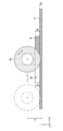
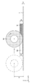
図17は、切り抜け側のダイシングテープ領域において切削痕を形成する手順を示す図である。図17(a)は側面図であり、図17(b)は平面図(図17(a)のXVIIB矢視図)である。
本実施形態では、ブレード18が切り抜け側のダイシングテープ領域Rに移動すると、制御部56(切削痕形成制御部)は、矢印A1に示すように、ブレード18を-Z方向に移動(下降)させて、ダイシングテープTに切り込ませる。このとき、ブレード18は、ワークWに接触しないように、ZX方向の位置が調整される。
ここで、矢印A1の位置におけるブレード18の切り込み深さの調整は、目視又は撮像装置22によりリアルタイムでダイシングテープTの表面を観察することにより手動で行ってもよい。また、スピンドル20にかかるトルクを測定するためのセンサを設けて、トルクの変化に応じて、制御部56が、切削痕28(i)の形成時の深さを自動的に調整するようにしてもよい。この場合、テープの種類(例えば、材質、厚さ)とトルクの変動との関係に関するデータを記憶部54に記憶しておき、制御部56は、このデータに基づいてブレード18の切り込み深さを判定可能としてもよい。
次に、制御部56は、矢印A2に示すように、ブレード18とワークWとをX方向に相対的に移動させながら、ダイシングテープTから離れる方向(+Z方向)にブレード18を連続的に移動(上昇)させる。このとき、ブレード18の移動(上昇)速度の大きさは、矢印A1に示すブレード18の下降時の移動速度の大きさよりも小さくする。制御部56は、ブレード18とワークWのZX方向の相対位置に関するログデータを取得し、記憶部54に記憶させる。
図17(a)に示すように、ブレード18がダイシングテープTの表面から離れると、図17(b)に示すように、切削痕28が形成されなくなる(途切れる)。撮像装置22は、切削痕28が途切れた切削痕消失点PEを含む切削痕28の画像を撮像する(図5から図7参照)。制御部56は、切削痕消失点PEを画像から検出し、切削痕消失点PEに対応するブレード18の中心の座標(XE,ZE)を含む切削痕情報を作成して、記憶部54に記憶させる。そして、制御部56は、この切削痕消失点PEにおけるZ座標ZE、及びダイシングテープTの表面のZ座標ZTから、ブレード18の径rB(=|ZE-ZT|)を算出する。
次に、制御部56は、ブレード18のZ方向の最下点とダイシングテープTとの間の位置関係を計算し、次の加工ラインS(i)に移動したときに、切削痕情報に基づいてブレード18の高さ制御を行う。このとき、制御部56は、ブレード18の径rB、ワークWの表面の座標及び厚さ、並びにダイシングテープTの表面の座標に基づいて、ダイシングテープTへの切り込み深さが一定となるようにブレード18の高さを制御する。
図18は、切り抜け側のダイシングテープ領域Rに形成された切削痕を示す平面図(写真)である。
図18に示す例では、加工ラインS(j×k+1)及びS(j×(k+1)+1)において、切削痕形成動作が行われているため、他の加工ラインと比較して、切削痕28が鮮明に形成されている。これにより、制御部56は、画像から切削痕28(i)の途切れた位置を容易に検出することができる。
[ダイシング方法]
次に、本実施形態に係るダイシング方法について、図19を参照して説明する。図19は、本発明の第2の実施形態に係るダイシング方法を示すフローチャートである。
次に、本実施形態に係るダイシング方法について、図19を参照して説明する。図19は、本発明の第2の実施形態に係るダイシング方法を示すフローチャートである。
まず、第1番目の加工ラインS(1)の切削が開始されると(ステップS30)、制御部56は、ブレード18の高さの制御を行う(ステップS32)。ステップS32では、例えば、記憶部54に記憶されたブレード18の径の設計値、又は直前のダイシング加工で算出したブレード18の径に基づいてブレード18の高さ制御を行う。
次に、加工ラインS(1)に対してダイシング加工(切削)が実施される(ステップS34)。
加工ラインS(1)の切削が終了し、ブレード18が切り抜け側のダイシングテープ領域Rに移動すると、制御部56は、切削痕形成動作を行う(ステップS40)。ステップS40では、制御部56は、図17に示すように、ダイシングテープ領域Rにおいて、ブレード18を下降させた後、X方向に走査させながら徐々に連続的に上昇させることにより、切削痕28を形成する。このとき、制御部56は、各時点におけるブレード18の座標のログデータを作成し、記憶部54に記憶させる。
次に、撮像装置22は、加工ラインS(1)の切り抜け側に形成された切削痕28を撮像する。制御部56は、切削痕28を撮像した画像から切削痕消失点PEを検出し、切削痕消失点PEの座標を含む切削痕情報を検出する(ステップS42)。制御部56は、この切削痕情報に基づいて、ブレード18の径rBを算出する(ステップS44)。ブレード18の径rBは、記憶部54に記憶される。
次に、制御部56は、次の加工ラインS(2)の切削が開始され、加工ラインS(2)にブレード18を移動させる(ステップS46)。制御部56は、切削痕情報を用いて算出したブレード18の径に基づきブレード18の高さを制御し(ステップS48)、加工ラインS(2)の切削を実施する(ステップS34)。ステップS48では、ダイシングテープTへの切り込み深さが一定となるようにブレード18の高さが制御される。
以下、ステップS34からS52が繰り返されて、S(3)以降の加工ラインの切削が実施される。切削痕情報に基づくブレード18の高さの制御は、jラインおきに行われる。
すなわち、i=j×k+1(jは1以上の整数、kは0以上の整数)の場合には(ステップS38のYes)、ステップS40に進み、加工ラインS(i)の切り抜け側のダイシングテープ領域Rにおいて、切削痕形成動作(ステップS40)及び切削痕検出動作(ステップS42)、切削痕情報に基づくブレード18の径rBの算出(ステップS44)、並びに次の加工ラインS(i)の切削時おけるブレード18の高さ制御(ステップS46及びS48)が行われる。ステップS44では、記憶部54に記憶されたブレード18の径rBが更新される。
一方、i≠j×k+1の場合には(ステップS38のNo)、次の加工ラインに移動後(ステップS50)、ブレード18の高さの制御が行われる(ステップS52)。ステップS52では、記憶部54に記憶されたブレード18の径rBの最新の値に基づいてブレード18の高さの制御が行われるようにしてもよい。
そして、全ての加工ラインS(i)の切削が終了すると(ステップS36のYes)、図19の処理を終了する。
[本実施形態の作用効果]
次に、本実施形態の作用効果について説明する。
次に、本実施形態の作用効果について説明する。
本実施形態によれば、ダイシングテープ領域R(ワークWが貼り付けられていない切り抜け側のダイシングテープTの表面領域)における切削痕情報に基づいて、ダイシングテープTへの切り込み深さが一定となるようにブレード18の高さが制御される。これにより、ダイシングテープTの厚さばらつきなどの影響を受けることなく、ブレード18がダイシングテープTに切り込む深さを比較的浅くかつ一定にすることが可能となるので、加工品質の安定化を図ることができる。
また、加工ライン数(例えば2067ライン)が多い場合、全ての加工ラインSのダイシング加工が完了するまでのブレード摩耗量は無視できない。そのため、従来は、ダイシング加工中に何度もカッターセットを実施して現在のブレード摩耗量を計測し、ブレード18の高さを調整する必要があった。これに対し、本実施形態では、ワークWのダイシング加工中において、切削痕形成及び検出動作が行われるため、現在のブレード摩耗量をリアルタイムで把握できる。このため、従来のようなブレード摩耗量の計測動作を頻繁に行うことが不要となり、ダイシング加工が完了するまでの時間を減らせることができるというメリットがある。
また、本実施形態では、切り抜け側となるダイシングテープ領域Rにおいて切削痕28を形成及び検出を行っているが、本発明はこれに限定されない。例えば、切削痕形成及び検出動作は、切り込み側と切り抜け側のダイシングテープ領域の両方で行ってもよいし、切り込み側のダイシングテープ領域のみで行ってもよい。
[他の実施形態]
図20は、他の実施形態に係るダイシング装置10Aの構成を示した概略図である。図20中、図1と共通する構成要素には同一の符号を付して、その説明を省略する。
図20は、他の実施形態に係るダイシング装置10Aの構成を示した概略図である。図20中、図1と共通する構成要素には同一の符号を付して、その説明を省略する。
図20に示すように、他の実施形態に係るダイシング装置10Aは、本実施形態に係るダイシング装置10の構成に加え、距離測定装置32を備えている。
距離測定装置32は、ワークテーブル12の対向位置に配置されている。距離測定装置32は、測定対象物であるダイシングテープ領域Rの表面までの距離を測定するものであり、例えば、レーザー変位計や干渉顕微鏡などで構成される。距離測定装置32の測定結果は距離データとして切削痕検出部52に出力される。
また、距離測定装置32は、撮像装置22の側面に固定されており、スピンドル20及び撮像装置22と一体となってY方向及びZ方向に移動可能となっている。
かかる構成により、ワークWがダイシング中に行われる切削痕検出動作(第1の実施形態)又は切削痕形成及び検出動作(第2の実施形態)として、距離測定装置32は、ダイシングテープ領域Rに対する位置をX方向にずらしながら、ダイシングテープ領域Rまでの距離を測定する。距離測定装置32の測定結果である距離データは切削痕検出部52に出力される。
切削痕検出部52は、距離測定装置32から取得した距離データに基づき、ダイシングテープ領域Rにおける高さの変化(凹凸状態)を示す高さグラフを生成する。
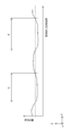
図21は、切削痕検出部52で生成される高さグラフの一例を示した図である。図21に示すように、切削痕検出部52は、生成した高さグラフにおいて、所定の閾値高さ(図21において破線で示した高さ)よりも低い領域を切削痕形成領域K(切削痕28が形成された領域)として検出する。そして、切削痕検出部52は、検出した切削痕形成領域Kに基づいて、切削痕形成率Qを算出する。その後の処理は本実施形態と同様である。
他の実施形態によれば、距離測定装置32の測定結果に基づいてダイシングテープ領域R(ワークWが貼り付けられていないダイシングテープTの表面領域)における切削痕情報を検出することができるので、上述した本実施形態と同様に加工品質の安定化を図ることが可能となる。
本発明の一例について詳細に説明したが、本発明は、これに限定されず、本発明の要旨を逸脱しない範囲において、各種の改良や変形を行ってもよいのはもちろんである。
10…ダイシング装置、12…ワークテーブル、14…θテーブル、16…Xテーブル、18…ブレード、20…スピンドル、22…撮像装置、24…保持部材、26…切削溝、28…切削痕、30…ラインセンサカメラ、32…距離測定装置、50…制御装置、52…切削痕検出部、54…記憶部、56…制御部、70…板状部材、90…ブレード、92…切削溝、94…切削痕、W…ワーク、T…ダイシングテープ、Q…切削痕形成率、G…ブレード高さ補正量
Claims (19)
- ワークテーブルにダイシングテープを介してワークを保持した状態で、スピンドルにより回転するブレードと前記ワークテーブルとを相対移動させてダイシング加工を行うダイシング装置であって、
前記ワークが貼り付けられていない前記ダイシングテープの表面領域に形成された切削痕情報を検出する切削痕検出部と、
前記切削痕検出部が検出した前記切削痕情報に基づき、前記ダイシングテープへの切り込み深さが一定となるように前記ブレードの高さを制御する制御部と、
を備えるダイシング装置。 - ワークテーブルにダイシングテープを介してワークを保持した状態で、スピンドルにより回転するブレードと前記ワークテーブルとを相対移動させてダイシング加工を行うダイシング装置であって、
前記ワークが貼り付けられておらず、かつ、前記ブレードと前記ワークテーブルとの相対移動方向に沿って周期的に凹凸が設けられた前記ダイシングテープの表面領域に形成された切削痕情報を検出する切削痕検出部と、
前記切削痕検出部が検出した前記切削痕情報に基づき、前記ダイシングテープへの切り込み深さが一定となるように前記ブレードの高さを制御する制御部と、
を備えるダイシング装置。 - 前記ワークテーブルと前記ダイシングテープとの間に配置され、前記ブレードと前記ワークテーブルとの相対移動方向に沿って周期的に凹凸が形成された板状部材を更に備え、
前記板状部材を介して前記ダイシングテープを前記ワークテーブルに吸着することにより、前記ダイシングテープの表面領域に凹凸が形成される、
請求項2に記載のダイシング装置。 - 前記ワークテーブルの表面には、前記ブレードと前記ワークテーブルとの相対移動方向に沿って周期的に凹凸が形成されており、
前記ダイシングテープを前記ワークテーブルに吸着することにより、前記ダイシングテープの表面領域に凹凸が形成される、
請求項2に記載のダイシング装置。 - 請求項2に記載のダイシング装置に用いられるダイシングテープであって、
前記ダイシングテープの基材及び接着剤層の少なくとも一方に設けられた凹凸を有し、前記凹凸により前記ダイシングテープの表面領域の凹凸が構成されたダイシングテープ。 - 前記切削痕検出部は、前記切削痕情報に基づいて前記ダイシングテープの表面領域における切削痕形成率を算出し、
前記制御部は、前記切削痕検出部が算出した前記切削痕形成率に基づいて、前記切削痕形成率が一定の範囲内となるように前記ブレードの高さを制御する、
請求項1に記載のダイシング装置。 - 前記ワークが貼り付けられていない前記ダイシングテープの表面領域において切削痕を形成する切削痕形成制御部であって、前記ブレードと前記ワークテーブルとの相対移動に伴って前記ブレードを前記ダイシングテープから離れる方向に移動させて切削痕消失点を形成する切削痕形成制御部をさらに備え、
前記切削痕検出部は、前記切削痕消失点の位置に関する情報を含む切削痕情報を検出する、
請求項1に記載のダイシング装置。 - 前記ワークテーブルの対向位置に配置された撮像装置を備え、
前記切削痕検出部は、前記撮像装置で撮像された前記ダイシングテープの表面領域の画像データに基づいて前記切削痕情報を検出する、
請求項1から4、6及び7のいずれか1項に記載のダイシング装置。 - 前記撮像装置はアライメント用カメラで構成される、
請求項8に記載のダイシング装置。 - 前記ワークテーブルの対向位置に配置された距離測定装置を備え、
前記切削痕検出部は、前記距離測定装置で測定された前記ダイシングテープの表面領域までの距離を示す距離データに基づいて前記切削痕情報を検出する、
請求項1から4、6及び7のいずれか1項に記載のダイシング装置。 - ワークテーブルにダイシングテープを介してワークを保持した状態で、スピンドルにより回転するブレードと前記ワークテーブルとを相対移動させてダイシング加工を行うダイシング方法であって、
前記ワークが貼り付けられていない前記ダイシングテープの表面領域に形成された切削痕情報を検出する検出ステップと、
前記検出ステップで検出した前記切削痕情報に基づき、前記ダイシングテープへの切り込み深さが一定となるように前記ブレードの高さを制御する制御ステップと、
を備えるダイシング方法。 - 前記ワークが貼り付けられていない前記ダイシングテープの表面領域において切削痕を形成するステップであって、前記ブレードと前記ワークテーブルとの相対移動に伴って前記ブレードを前記ダイシングテープから離れる方向に移動させて切削痕消失点を形成する形成ステップをさらに備え、
前記検出ステップでは、前記切削痕消失点の位置に関する情報を含む切削痕情報を検出する、
請求項11に記載のダイシング方法。 - 前記切削痕を形成する際の各時点におけるブレードの位置に関するログデータを記憶するステップを更に備え、
前記検出ステップにおいて、前記切削痕消失点の位置に関する情報を前記ログデータから取得する、
請求項12に記載のダイシング方法。 - 前記形成ステップにおいて、前記ワークの切り抜け側のダイシングテープ領域に前記切削痕を形成する、
請求項12又は13に記載のダイシング方法。 - 前記形成ステップ及び前記検出ステップは、少なくとも1の加工ラインおきに行われる、
請求項12から14のいずれか1項に記載のダイシング方法。 - ワークテーブルにダイシングテープを介してワークを保持した状態で、スピンドルにより回転するブレードと前記ワークテーブルとを相対移動させてダイシング加工を行うダイシング方法であって、
前記ワークが貼り付けられておらず、かつ、前記ブレードと前記ワークテーブルとの相対移動方向に沿って周期的に凹凸が設けられた前記ダイシングテープの表面領域に形成された切削痕情報を検出する検出ステップと、
前記検出ステップで検出した前記切削痕情報に基づき、前記ダイシングテープへの切り込み深さが一定となるように前記ブレードの高さを制御する制御ステップと、
を備えるダイシング方法。 - 前記ダイシングテープの基材及び接着剤層の少なくとも一方に凹凸を設けることにより、前記ダイシングテープの表面領域に凹凸が形成される、
請求項16に記載のダイシング方法。 - 前記ブレードと前記ワークテーブルとの相対移動方向に沿って周期的に凹凸が形成された板状部材を、前記ワークテーブルと前記ダイシングテープとの間に配置し、
前記板状部材を介して前記ダイシングテープを前記ワークテーブルに吸着することにより、前記ダイシングテープの表面領域に凹凸が形成される、
請求項16に記載のダイシング方法。 - 前記ワークテーブルの表面には、前記ブレードと前記ワークテーブルとの相対移動方向に沿って周期的に凹凸が形成されており、
前記ダイシングテープを前記ワークテーブルに吸着することにより、前記ダイシングテープの表面領域に凹凸を形成する、
請求項16に記載のダイシング方法。
Priority Applications (3)
| Application Number | Priority Date | Filing Date | Title |
|---|---|---|---|
| CN201880088934.1A CN111699545B (zh) | 2018-02-08 | 2018-11-09 | 切割装置以及切割方法 |
| CN202011396997.9A CN112536700B (zh) | 2018-02-08 | 2018-11-09 | 切割方法以及切割装置 |
| CN202110555098.7A CN113290484B (zh) | 2018-02-08 | 2018-11-09 | 切割装置、切割方法以及切割带 |
Applications Claiming Priority (8)
| Application Number | Priority Date | Filing Date | Title |
|---|---|---|---|
| JP2018-021222 | 2018-02-08 | ||
| JP2018021222 | 2018-02-08 | ||
| JP2018-163613 | 2018-08-31 | ||
| JP2018163613 | 2018-08-31 | ||
| JP2018-163614 | 2018-08-31 | ||
| JP2018163614 | 2018-08-31 | ||
| JP2018-163615 | 2018-08-31 | ||
| JP2018163615 | 2018-08-31 |
Publications (1)
| Publication Number | Publication Date |
|---|---|
| WO2019155707A1 true WO2019155707A1 (ja) | 2019-08-15 |
Family
ID=67549577
Family Applications (1)
| Application Number | Title | Priority Date | Filing Date |
|---|---|---|---|
| PCT/JP2018/041727 Ceased WO2019155707A1 (ja) | 2018-02-08 | 2018-11-09 | ダイシング装置及びダイシング方法並びにダイシングテープ |
Country Status (3)
| Country | Link |
|---|---|
| JP (3) | JP6748892B2 (ja) |
| CN (3) | CN113290484B (ja) |
| WO (1) | WO2019155707A1 (ja) |
Cited By (3)
| Publication number | Priority date | Publication date | Assignee | Title |
|---|---|---|---|---|
| US20200185241A1 (en) * | 2018-12-11 | 2020-06-11 | Disco Corporation | Cutting apparatus and wafer processing method using cutting apparatus |
| JP2022040746A (ja) * | 2020-08-31 | 2022-03-11 | 株式会社ディスコ | ウェーハの加工方法 |
| CN117790294A (zh) * | 2023-12-29 | 2024-03-29 | 沈阳和研科技股份有限公司 | 一种用于划片机的切割刀高度调整方法、装置及划片机 |
Families Citing this family (4)
| Publication number | Priority date | Publication date | Assignee | Title |
|---|---|---|---|---|
| JP2022080757A (ja) * | 2020-11-18 | 2022-05-30 | 株式会社ディスコ | 切削ブレードの直径測定方法 |
| JP7853775B2 (ja) * | 2021-10-12 | 2026-04-30 | 芝浦機械株式会社 | 加工機及び被加工物の製造方法 |
| CN114057384B (zh) * | 2021-12-10 | 2024-06-11 | 青岛天仁微纳科技有限责任公司 | 一种扫描电镜辅助定位裂片装置及使用方法 |
| CN117301328A (zh) * | 2023-10-20 | 2023-12-29 | 北京中电科电子装备有限公司 | 一种晶片切割装置、划膜测高方法及切割方法 |
Citations (3)
| Publication number | Priority date | Publication date | Assignee | Title |
|---|---|---|---|---|
| JPH03227557A (ja) * | 1990-02-01 | 1991-10-08 | Mitsubishi Electric Corp | ダイシング装置 |
| JP2013041972A (ja) * | 2011-08-15 | 2013-02-28 | Disco Abrasive Syst Ltd | 切削方法 |
| JP2016192494A (ja) * | 2015-03-31 | 2016-11-10 | 株式会社ディスコ | ウエーハの分割方法 |
Family Cites Families (12)
| Publication number | Priority date | Publication date | Assignee | Title |
|---|---|---|---|---|
| JP2003124155A (ja) * | 2001-10-12 | 2003-04-25 | Disco Abrasive Syst Ltd | 切削装置 |
| JP2005203540A (ja) * | 2004-01-15 | 2005-07-28 | Disco Abrasive Syst Ltd | ウエーハの切削方法 |
| JP4554265B2 (ja) * | 2004-04-21 | 2010-09-29 | 株式会社ディスコ | 切削ブレードの位置ずれ検出方法 |
| JP4748643B2 (ja) * | 2005-01-28 | 2011-08-17 | 株式会社ディスコ | 切削ブレードの基準位置検出方法 |
| JP4943688B2 (ja) * | 2005-10-21 | 2012-05-30 | 株式会社ディスコ | 切削装置 |
| JP5340808B2 (ja) * | 2009-05-21 | 2013-11-13 | 株式会社ディスコ | 半導体ウエーハのレーザ加工方法 |
| JP5647510B2 (ja) * | 2010-12-27 | 2014-12-24 | 株式会社小金井精機製作所 | 切削加工装置及び切削加工方法 |
| JP6219628B2 (ja) * | 2013-07-17 | 2017-10-25 | 株式会社ディスコ | 切削ブレード先端形状検出方法 |
| JP6228044B2 (ja) * | 2014-03-10 | 2017-11-08 | 株式会社ディスコ | 板状物の加工方法 |
| JP2016019249A (ja) * | 2014-07-11 | 2016-02-01 | キヤノン株式会社 | 表示制御装置 |
| JP2016063060A (ja) * | 2014-09-18 | 2016-04-25 | 株式会社ディスコ | ウエーハの加工方法 |
| CN106334989A (zh) * | 2016-11-02 | 2017-01-18 | 佛山市百思科铁芯制造有限公司 | 一种变压器铁芯专用切割机 |
-
2018
- 2018-11-09 JP JP2018211636A patent/JP6748892B2/ja active Active
- 2018-11-09 JP JP2018211634A patent/JP6748891B2/ja active Active
- 2018-11-09 WO PCT/JP2018/041727 patent/WO2019155707A1/ja not_active Ceased
- 2018-11-09 CN CN202110555098.7A patent/CN113290484B/zh active Active
- 2018-11-09 JP JP2018211635A patent/JP6768185B2/ja active Active
- 2018-11-09 CN CN201880088934.1A patent/CN111699545B/zh active Active
- 2018-11-09 CN CN202011396997.9A patent/CN112536700B/zh active Active
Patent Citations (3)
| Publication number | Priority date | Publication date | Assignee | Title |
|---|---|---|---|---|
| JPH03227557A (ja) * | 1990-02-01 | 1991-10-08 | Mitsubishi Electric Corp | ダイシング装置 |
| JP2013041972A (ja) * | 2011-08-15 | 2013-02-28 | Disco Abrasive Syst Ltd | 切削方法 |
| JP2016192494A (ja) * | 2015-03-31 | 2016-11-10 | 株式会社ディスコ | ウエーハの分割方法 |
Cited By (5)
| Publication number | Priority date | Publication date | Assignee | Title |
|---|---|---|---|---|
| US20200185241A1 (en) * | 2018-12-11 | 2020-06-11 | Disco Corporation | Cutting apparatus and wafer processing method using cutting apparatus |
| JP2022040746A (ja) * | 2020-08-31 | 2022-03-11 | 株式会社ディスコ | ウェーハの加工方法 |
| JP7562230B2 (ja) | 2020-08-31 | 2024-10-07 | 株式会社ディスコ | ウェーハの加工方法 |
| CN117790294A (zh) * | 2023-12-29 | 2024-03-29 | 沈阳和研科技股份有限公司 | 一种用于划片机的切割刀高度调整方法、装置及划片机 |
| CN117790294B (zh) * | 2023-12-29 | 2026-02-06 | 沈阳和研科技股份有限公司 | 一种用于划片机的切割刀高度调整方法、装置及划片机 |
Also Published As
| Publication number | Publication date |
|---|---|
| CN111699545A (zh) | 2020-09-22 |
| JP6748891B2 (ja) | 2020-09-02 |
| CN112536700A (zh) | 2021-03-23 |
| JP6748892B2 (ja) | 2020-09-02 |
| CN113290484A (zh) | 2021-08-24 |
| JP2020037171A (ja) | 2020-03-12 |
| CN112536700B (zh) | 2022-04-29 |
| JP2020037170A (ja) | 2020-03-12 |
| JP6768185B2 (ja) | 2020-10-14 |
| JP2020037169A (ja) | 2020-03-12 |
| CN113290484B (zh) | 2023-04-25 |
| CN111699545B (zh) | 2021-09-14 |
Similar Documents
| Publication | Publication Date | Title |
|---|---|---|
| WO2019155707A1 (ja) | ダイシング装置及びダイシング方法並びにダイシングテープ | |
| JP7596631B2 (ja) | ダイシング装置及びダイシング方法 | |
| JP6228044B2 (ja) | 板状物の加工方法 | |
| JP5208644B2 (ja) | 加工方法および加工装置 | |
| JP5214332B2 (ja) | ウエーハの切削方法 | |
| TWI748082B (zh) | 雷射加工方法 | |
| JP5762005B2 (ja) | 加工位置調製方法及び加工装置 | |
| JP6229883B2 (ja) | ダイシング装置及びその切削方法 | |
| JP5722071B2 (ja) | 半導体デバイスの製造方法およびレーザー加工装置 | |
| JP2017183503A (ja) | ウェーハの面取り方法 | |
| CN109249285B (zh) | 修整板和修整方法 | |
| JP2011151117A (ja) | 加工装置 | |
| JP2017038028A (ja) | 切削ブレードの位置ずれ検出方法 | |
| JP6252838B2 (ja) | ダイシング装置及びその切削方法 | |
| JP2019075405A (ja) | ウェーハの加工方法 | |
| JP2012161888A (ja) | 加工方法 | |
| JP2009126006A (ja) | ワークの切削加工方法 | |
| JP6478794B2 (ja) | 角度付き切削ブレードの製造方法 | |
| US20250196385A1 (en) | Measuring method, measuring apparatus, and workpiece processing method | |
| JP2020116655A (ja) | 切削装置及び切削ブレードのドレッシング方法 | |
| JP2024149216A (ja) | パッケージ基板の分割方法 | |
| JP2022074236A (ja) | ウェーハの切削方法、及び、切削装置 |
Legal Events
| Date | Code | Title | Description |
|---|---|---|---|
| 121 | Ep: the epo has been informed by wipo that ep was designated in this application |
Ref document number: 18905855 Country of ref document: EP Kind code of ref document: A1 |
|
| NENP | Non-entry into the national phase |
Ref country code: DE |
|
| 122 | Ep: pct application non-entry in european phase |
Ref document number: 18905855 Country of ref document: EP Kind code of ref document: A1 |