WO2019150642A1 - 車両用キー - Google Patents
車両用キー Download PDFInfo
- Publication number
- WO2019150642A1 WO2019150642A1 PCT/JP2018/034038 JP2018034038W WO2019150642A1 WO 2019150642 A1 WO2019150642 A1 WO 2019150642A1 JP 2018034038 W JP2018034038 W JP 2018034038W WO 2019150642 A1 WO2019150642 A1 WO 2019150642A1
- Authority
- WO
- WIPO (PCT)
- Prior art keywords
- key
- housing
- annular member
- vehicle
- hole
- Prior art date
- Legal status (The legal status is an assumption and is not a legal conclusion. Google has not performed a legal analysis and makes no representation as to the accuracy of the status listed.)
- Ceased
Links
Images






Classifications
-
- E—FIXED CONSTRUCTIONS
- E05—LOCKS; KEYS; WINDOW OR DOOR FITTINGS; SAFES
- E05B—LOCKS; ACCESSORIES THEREFOR; HANDCUFFS
- E05B19/00—Keys; Accessories therefor
-
- E—FIXED CONSTRUCTIONS
- E05—LOCKS; KEYS; WINDOW OR DOOR FITTINGS; SAFES
- E05B—LOCKS; ACCESSORIES THEREFOR; HANDCUFFS
- E05B49/00—Electric permutation locks; Circuits therefor ; Mechanical aspects of electronic locks; Mechanical keys therefor
Definitions
- This disclosure relates to a vehicle key.
- a keyless entry system in which a user can unlock a vehicle door without using a key blade by pressing a button provided on a portable device.
- the user can unlock the door simply by approaching the vehicle while holding the portable device, and can start the engine simply by pressing the engine start button installed in the passenger compartment while holding the portable device.
- a smart keyless entry system is known.
- Patent Document 1 As a portable device used in an electronic key system such as a keyless entry system or a smart keyless entry system, a remote control device including a key blade is known (see Patent Document 1).
- This remote control device includes a key ring that passes through an attachment hole formed in the casing and an attachment hole formed in the grip portion of the key blade.
- a vehicle key includes a housing, a key blade extending from the housing and inserted into a key cylinder installed in the vehicle, and an annular member attached to a hole formed in the housing. And an elastic member that comes into contact with the housing and the annular member to suppress movement of the annular member within the hole.
- the above-described means provides an easy-to-use vehicle key that can suppress the sound caused by the vibration of the key ring that occurs when the key blade is inserted into the key cylinder provided in the vehicle.
- FIG. 1A It is a perspective view of the example of composition of the key for vehicles concerning the embodiment of the present invention. It is a disassembled perspective view of the vehicle key of FIG. 1A. It is a perspective view when the key for vehicles of Drawing 1A is seen from another angle. It is a perspective view when the key for vehicles of Drawing 1A is seen from another angle. It is a top view of the key for vehicles of Drawing 1A. It is a rear view of the vehicle key of FIG. 1A. It is sectional drawing of the vehicle key of FIG. 1A. It is a rear view which shows another structural example of the key for vehicles. It is sectional drawing of the vehicle key of FIG. 4A. It is an expanded sectional view of the hole formed in the housing
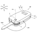
- FIG. 1A is a perspective view illustrating a configuration example of the vehicle key 100.
- FIG. 1B is an exploded perspective view of the vehicle key 100.
- the vehicle key 100 is a jack knife type portable device used in a keyless entry system, and mainly includes a housing 1, an operation button 2, a release button 3, a rotor 4, a key blade 5, an annular member 6, and an elastic member. 7 etc.
- the alternate long and short dash line represents the rotation axis CX of the rotor 4.
- the housing 1 accommodates the components of the vehicle key 100.
- the housing 1 is made of synthetic resin, and accommodates a transponder, a battery, a printed board, an LED, and the like (not shown) between the upper housing 1U and the lower housing 1L.
- the transponder is an example of communication means for realizing wireless communication between the vehicle key 100 and the in-vehicle device.
- the communication means may be realized by a device other than the transponder.
- the operation button 2 is a button that can be operated by a user carrying the vehicle key 100.
- the operation button 2 includes an unlock button 2U for unlocking the door and a lock button 2L for locking the door.
- the operation button 2 may include buttons that realize other functions. Further, the operation button 2 may be omitted. In this case, since the vehicle key 100 functions as a simple key, a transponder, a battery, a printed board, an LED, and the like are also omitted.
- the release button 3 is a button for making the key blade 5 stored in the housing 1 usable.
- the release button 3 is configured such that when the user presses the release button 3, the key blade 5 pops out and becomes usable.
- FIG. 1A shows that the key blade 5 is ready for use.
- the rotor 4 is a holding member that holds the key blade 5.
- the rotor 4 is formed of a synthetic resin or a metal material, and is configured to receive and hold the base portion of the key blade 5.
- the rotor 4 is disposed between the upper housing 1U and the lower housing 1L so as to be able to rotate together with the release button 3 around the rotation axis CX.
- FIG. 2 is a perspective view of the vehicle key 100 viewed from another angle. As shown in FIG. 2, the user of the vehicle key 100, for example, moves the key blade 5 around the rotation axis CX in the direction of the arrow AR1 while pressing the release button 3, thereby housing the key blade 5 in the casing. 1 can be stored.
- the key blade 5 is a blade in which grooves or protrusions corresponding to the mechanical key ID are formed.
- the mechanical key ID is information related to a shape pattern such as a groove or a protrusion. Specifically, the mechanical key ID is information specified by a shape pattern such as a groove or a protrusion.
- the annular member 6 is configured to be attached to a hole 1H formed in the housing 1.
- the annular member 6 is movably attached with respect to the housing 1 and is used to connect the housing 1 to another object.
- “Moved relative to the housing 1” means, for example, a configuration embedded and fixed in the housing 1 by insert molding or the like, a configuration fixed to the housing 1 by a hot melt adhesive, or the like, 1 means that it is not a structure formed integrally with 1.
- the annular member 6 is a card ring type, a double ring type, a split ring type, or the like without a user disassembling the casing 1, that is, without separating the upper casing 1U and the lower casing 1L. It may be a member of a type that is detachably attached to the body 1. Alternatively, a member that cannot be attached to and detached from the housing 1 such as a rigid ring type or a solid ring type, that is, a member that cannot be attached or detached unless the user disassembles the housing 1 may be used.
- the annular member 6 is configured such that a strap, a key holder, a key ring, or the like can be attached.
- the annular member 6 is a detachable metal annular key ring, and is attached to a hole 1H formed in the lower housing 1L constituting the housing 1.
- the annular member 6 may have another ring shape such as an elliptical ring, a triangular ring, a quadrangular ring, a pentagonal ring, or a hexagonal ring. Further, the annular member 6 may not be a complete ring.
- the annular member 6 may be formed of a material other than metal, such as a synthetic resin.
- the elastic member 7 is configured to be in contact with the housing 1 and the annular member 6 to suppress the movement of the annular member 6 in the hole H1.
- the elastic member 7 is detachably attached between the housing 1 and the annular member 6 and is attached in a stretched state. And the elastic member 7 urges
- the elastic member 7 is made of, for example, an elastomer.
- the elastic member 7 is a silicon rubber O-ring having an inner diameter smaller than the outer diameter of the annular key ring as the annular member 6.
- the elastic member 7 is not an O-ring having a circular cross section, but may be a rubber ring having a cross section other than a circular shape.
- the elastic member 7 may be a rubber ring having another ring shape such as an elliptical ring instead of an annular O-ring. Further, the elastic member 7 may not be a complete ring.
- FIGS. 3A to 3D are views of the vehicle key 100 with the annular member 6 and the elastic member 7 removed.
- FIG. 3A is a perspective view of the vehicle key 100 and corresponds to FIG. 1A.
- FIG. 3B is a top view of the vehicle key 100.
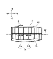
- FIG. 3C is a rear view of the vehicle key 100.
- 3D is a cross-sectional view of the XY plane including the alternate long and short dash line L1 illustrated in FIG. 3C when viewed from the + Z side.
- a notch 1C and a hole 1H are formed on the back surface ( ⁇ X side surface) of the housing 1.
- a notch 1C is formed on the back surface of the upper housing 1U constituting the housing 1
- a hole 1H is formed on the back surface of the lower housing 1L constituting the housing 1.
- the notch 1C is configured so that the tip of a tool such as a flat-blade screwdriver can be inserted when the lower housing 1L and the upper housing 1U are separated.
- An operator who wants to disassemble the vehicle key 100 inserts the tip of a minus driver into the notch 1C, and then rotates the minus driver about the axis, thereby lowering the lower casing 1L and the upper casing 1U. Can be separated.
- the cutout portion 1C is formed on the back surface of the upper housing 1U, but may be formed on the left side surface, the right side surface, or the front surface of the upper housing 1U. Further, the cutout portion 1C may be formed in the lower housing 1L. Further, the cutout portion 1C is formed in the vicinity of the hole 1H, but may be formed in a place away from the hole 1H.
- the hole 1H is configured to receive the annular member 6.
- the hole 1H is a through hole that connects the opening 1Ha and the opening 1Hb, and is configured to have an inverted V shape as shown in FIG. 3D.
- the inverted V shape is a shape resulting from the arrangement of two nestings used in injection molding.
- the hole 1H is configured such that its cross-sectional area is larger than the cross-sectional area of the annular member 6 so that the annular member 6 can be easily attached. That is, the hole 1H is configured so that the annular member 6 can translate and rotate within the hole 1H.
- the hole 1H is configured to hold the annular member 6 in a state where the center of the annular key ring as the annular member 6 is positioned outside the housing 1. This is to make the inner diameter of the elastic member 7 smaller than the outer diameter of the annular member 6 when the elastic member 7 is attached while being stretched between the housing 1 and the annular member 6.
- the hole 1H may be configured to have an inverted U shape as shown in FIG. 4B.
- 4A and 4B are diagrams showing another configuration example of the vehicle key 100.
- FIG. 4A is a rear view of the vehicle key 100 and corresponds to FIG. 3C.
- 4B is a cross-sectional view of the XY plane including the alternate long and short dash line L2 shown in FIG. 4A when viewed from the + Z side, and corresponds to FIG. 3D.
- the cutout portion 1C as shown in FIG. 3C is not formed on the back surface of the upper housing 1U.
- the housing 1 is configured such that the opening 1Ha and the opening 1Hb are connected to the upper edge (the edge on the + Z side) of the lower housing 1L. Therefore, an operator who intends to attach the annular member 6 to the housing 1 only needs to arrange the annular member 6 in the hole 1H of the lower housing 1L before assembling the lower housing 1L and the upper housing 1U.
- the annular member 6 may be, for example, a solid ring type key ring.
- the curvature radius CR of the inner wall of the hole 1H having the inverted U shape shown in FIG. 4B may be configured to be substantially the same as the inner diameter of the annular key ring as the annular member 6.
- the annular member 6 when the annular member 6 is urged by the elastic member 7 in a direction away from the casing 1, the annular member 6 comes into contact with the inner wall of the hole 1 ⁇ / b> H with a larger contact area than in the case of the inverted V shape. Therefore, it is more stably held by the housing 1.
- FIGS. 5A to 5C and FIG. 5A to 5C are enlarged sectional views of the hole 1H, and correspond to an enlarged view of the region Q in FIG. 3D.
- FIG. 5A shows a state when the annular member 6 is not attached.
- FIG. 5B shows a state where the annular member 6 is attached and the elastic member 7 is not attached.
- FIG. 5C shows a state when the annular member 6 and the elastic member 7 are attached.
- 6 is an enlarged rear view of the hole 1H and corresponds to an enlarged view of the region R in FIG. 3C.
- both FIG. 6A and FIG. 6B show a state when the annular member 6 is attached and the elastic member 7 is not attached.
- the annular member 6 shown by a solid line in FIG. 5B represents a state when moving to the rearmost side ( ⁇ X side), and the annular member 6A shown by a broken line is the frontmost side. This represents the state when moving to (+ X side).
- the annular member 6 comes into contact with the support member 1P constituting the inner wall of the hole 1H at the point P1 when moved to the rearmost side, and the outer wall of the hole 1H at the point P2 and the point P3 when moved to the frontmost side. Contact.
- the annular member 6 in a state where the elastic member 7 is not attached, can move by a distance D1 in the front-rear direction (X-axis direction). Moreover, as shown in FIG. 6, in the state where the elastic member 7 is not attached, the annular member 6 is movable by a distance D2 in the vertical direction (Z-axis direction). Further, in a state where the elastic member 7 is not attached, the annular member 6 can rotate about the X axis, the Y axis, and the Z axis in addition to the parallel movement in the front-rear direction and the parallel movement in the vertical direction.
- the elastic member 7 when the elastic member 7 is attached, the annular member 6 is held in the state shown in FIG. 5C. Specifically, the elastic member 7 in the stretched state tries to return to the original shape while contacting the annular member 6 at the points P4 and P5. Therefore, the elastic member 7 tends to contract as indicated by the arrows AR2 and AR3, and further slides along the outer periphery of the annular member 6 as indicated by the arrows AR4 and AR5. As a result, the elastic member 7 urges the annular member 6 so as to push the annular member 6 backward ( ⁇ X direction), that is, away from the casing 1 as indicated by an arrow AR6. Acts as follows.
- the annular member 6 is held in a state of being pressed against the support member 1P.
- the elastic member 7 can suppress vibration of the annular member 6 in the hole H1.
- the length of the chord connecting the points P4 and P5 (the distance between the points P4 and P5), which is the inner diameter of the elastic member 7, is smaller than the outer diameter of the annular member 6. Therefore, the elastic member 7 does not fall off from the annular member 6.
- the inner diameter of the elastic member 7 that is not stretched is the width W1 of the column member 1P (see FIG. 5A) so as to provide a biasing force sufficient to hold the annular member 6. Smaller than.)
- the inner diameter of the elastic member 7 that is not stretched may be larger than the width W1 of the column member 1P.
- FIG. 7 is a perspective view of the vehicle key 100 inserted into the key cylinder in the vehicle interior.
- the driver uses the vehicle until the blade surface 5S (see FIG. 2) of the key blade 5 is inclined by the angle ⁇ with respect to the vertical axis.
- the key 100 is rotated to activate the engine.
- the angle ⁇ is an acute angle, but may be an obtuse angle.
- the blade surface 5S may be a surface parallel to the XZ plane.
- the vehicle key 100 may be configured such that the blade surface 5S is parallel or perpendicular to the vertical axis when the engine is in an operating state. That is, the annular key ring as the annular member 6 may be configured to be parallel or perpendicular to the vertical axis.
- a plurality of keys KY are connected to the annular member 6 via another key ring KR. Even in such a case, the elastic member 7 can suppress the annular member 6 from swinging in the hole 1H formed in the housing 1.
- FIG. 8 is a rear perspective view of still another configuration example of the vehicle key 100. 8 differs from the vehicle key 100 of FIG. 1A in that the hole 1H is formed in the upper housing 1U and the elastic member 7 is a rubber band. It is common in. With this configuration, the vehicle key 100 of FIG. 8 can achieve the same effect as the effect of the vehicle key 100 of FIG. 1A.
- the vehicle key 100 is formed in the housing 1, the key blade 5 extending from the housing 1 and inserted into the key cylinder installed in the vehicle, and the housing 1.
- An annular member 6 attached to the hole 1H, and an elastic member 7 that contacts the housing 1 and the annular member 6 and suppresses the movement of the annular member 6 in the hole 1H.
- the vehicle key 100 can suppress noise caused by the vibration of the annular member 6 that occurs when the key blade 5 is inserted into a key cylinder provided in the vehicle. This effect is particularly desirable for improving the comfort in the passenger compartment where the noise reduction is realized.
- the elastic member 7 is arranged so as to urge and press the annular member 6 from the inner side to the outer side of the casing 1 against a part of the casing 1 forming the hole 1H, for example. Also good. Specifically, the elastic member 7 is disposed so as to urge the annular member 6 in the direction from the inside to the outside of the housing 1 and press the annular member 6 against the support member 1P as indicated by an arrow AR6 in FIG. 5C. May be. In this case, the support member 1P is a part of the housing 1 in which the hole 1H is formed.
- the elastic member 7 is, for example, an O-ring or a rubber band. Therefore, the vehicle key 100 can suppress the sound caused by the vibration of the annular member 6 easily and inexpensively. Further, the performance of the vehicle key 100 is not affected, and the load on the production line is not increased.
- the vehicle key 100 is configured as a jack knife type key, but as a key of a type other than the jack knife type such as a type in which the key blade 5 is fixed in an exposed state. It may be configured.
- the opening 1Ha and the opening 1Hb are formed so as to be aligned in the Y-axis direction, but may be formed so as to be aligned in the Z-axis direction, and are inclined with respect to the Y-axis and the Z-axis. You may form so that it may rank with a direction.
- the hole 1H is formed on the back surface of the housing 1.
- the hole 1H may be formed on the right side surface, left side surface, top surface, or bottom surface of the housing 1.
Landscapes
- Lock And Its Accessories (AREA)
Abstract
本発明の実施形態に係る車両用キー(100)は、筐体(1)と、筐体(1)から延び且つ車両に設置されたキーシリンダに差し込まれるキーブレード(5)と、筐体(1)に形成された孔(1H)に取り付けられる環状部材(6)としてのキーリングと、筐体(1)及びキーリングに接触して孔(1H)内でのキーリングの動きを抑える弾性部材(7)としてのOリングと、を備えている。
Description
本開示は、車両用キーに関する。
従来、使用者が携帯機に設けられたボタンを押すことでキーブレードを使用せずに車両のドアを解錠できるようにするキーレスエントリーシステムが知られている。また、使用者が携帯機を所持しながら車両に近づくだけでドアを解錠でき、且つ、携帯機を所持しながら車室内に設置されているエンジンスタートボタンを押すだけでエンジンを始動できるようにするスマートキーレスエントリーシステムが知られている。
そして、キーレスエントリーシステム又はスマートキーレスエントリーシステム等の電子キーシステムで利用される携帯機として、キーブレードを備えたリモコン装置が知られている(特許文献1参照。)。
このリモコン装置は、筐体に形成された取付孔とキーブレードの把持部に形成された取付孔とを通るキーリングを備えている。
しかしながら、上述のリモコン装置を所持している使用者は、車両に設けられているキーシリンダの鍵穴にキーブレードを差し込む際、筐体からキーブレードを抜き取るためにキーリングを分割する必要があり、煩雑である。また、キーブレードの把持部に形成された取付孔にキーリングが取り付けられた状態でキーブレードがキーシリンダの鍵穴に差し込まれると、車両走行中の振動等により、キーブレードとキーリングとが擦れ合う音が発生してしまうおそれがある。
そこで、車両に設けられているキーシリンダにキーブレードが差し込まれた状態で発生するキーリングの振動に起因する音を抑制できる使いやすい車両用キーを提供することが望まれる。
本発明の実施形態に従った車両用キーは、筐体と、前記筐体から延び且つ車両に設置されたキーシリンダに差し込まれるキーブレードと、前記筐体に形成された孔に取り付けられる環状部材と、前記筐体及び前記環状部材に接触して前記孔内での前記環状部材の動きを抑える弾性部材と、を備える。
上述の手段により、車両に設けられているキーシリンダにキーブレードが差し込まれた状態で発生するキーリングの振動に起因する音を抑制できる使いやすい車両用キーが提供される。
以下、図を参照し、本発明の実施形態に係る車両用キー100について説明する。図1Aは、車両用キー100の構成例を示す斜視図である。図1Bは、車両用キー100の分解斜視図である。車両用キー100は、キーレスエントリーシステムで利用されるジャックナイフタイプの携帯機であり、主に、筐体1、操作ボタン2、リリースボタン3、ロータ4、キーブレード5、環状部材6及び弾性部材7等で構成されている。一点鎖線は、ロータ4の回動軸CXを表す。
筐体1は、車両用キー100の構成要素を収容する。本実施形態では、筐体1は、合成樹脂で形成され、上部筐体1Uと下部筐体1Lとの間に不図示のトランスポンダ、電池、プリント基板及びLED等を収容している。トランスポンダは、車両用キー100と車載機との間での無線通信を実現する通信手段の一例である。通信手段は、トランスポンダ以外の他の装置で実現されてもよい。
操作ボタン2は、車両用キー100を携帯する使用者が操作可能なボタンである。本実施形態では、操作ボタン2は、ドアを解錠する解錠ボタン2U、及び、ドアを施錠する施錠ボタン2Lを含む。操作ボタン2は、他の機能を実現するボタンを含んでいてもよい。また、操作ボタン2は省略されてもよい。この場合、車両用キー100は、単なるキーとして機能するため、トランスポンダ、電池、プリント基板及びLED等も省略される。
リリースボタン3は、筐体1内に収納されているキーブレード5を使用可能な状態にするボタンである。本実施形態では、リリースボタン3は、使用者がリリースボタン3を押すとキーブレード5が飛び出して使用可能な状態となるように構成されている。図1Aは、キーブレード5が使用可能な状態にあることを示している。
ロータ4は、キーブレード5を保持する保持部材である。本実施形態では、ロータ4は、合成樹脂又は金属材で形成され、キーブレード5の基部を受け入れて保持するように構成されている。また、ロータ4は、回動軸CXの回りでリリースボタン3と共に回動できるように上部筐体1Uと下部筐体1Lとの間に配置されている。図2は、別の角度から見た車両用キー100の斜視図である。図2に示すように、車両用キー100の使用者は、例えば、リリースボタン3を押しながら回動軸CX回りでキーブレード5を矢印AR1の方向に回動させることでキーブレード5を筐体1内に収納できる。
キーブレード5は、メカニカルキーIDに対応する溝又は突起等が形成されるブレードである。メカニカルキーIDは、溝又は突起等の形状パターンに関する情報である。具体的には、メカニカルキーIDは、例えば、溝又は突起等の形状パターンで特定される情報である。
環状部材6は、筐体1に形成された孔1Hに取り付けられるように構成されている。環状部材6は、筐体1に関して可動的に取り付けられ、筐体1と他の物体とを連結するために用いられる。「筐体1に関して可動的に取り付けられる」は、例えば、インサート成形等によって筐体1に埋め込まれ且つ固定される構成、ホットメルト接着剤等によって筐体1に固定される構成、或いは、筐体1と一体的に形成される構成ではないことを意味する。
環状部材6は、カードリングタイプ、二重リングタイプ又はスプリットリングタイプ等、使用者が筐体1を分解することなく、すなわち、上部筐体1Uと下部筐体1Lとを分離することなく、筐体1に着脱可能に取り付けられるタイプの部材であってもよい。或いは、剛体リングタイプ又はソリッドリングタイプ等、筐体1に着脱不能に取り付けられるタイプ、すなわち、使用者が筐体1を分解しなければ着脱できないタイプの部材であってもよい。
環状部材6は、ストラップ、キーホルダ又はキーリング等が取り付けられるように構成されている。本実施形態では、環状部材6は、着脱可能な金属製の円環状のキーリングであり、筐体1を構成する下部筐体1Lに形成された孔1Hに取り付けられている。但し、環状部材6は、楕円環、三角環、四角環、五角環又は六角環等の他の環形状を有していてもよい。また、環状部材6は、完全な環でなくてもよい。また、環状部材6は、合成樹脂等、金属以外の材料で形成されていてもよい。
弾性部材7は、筐体1及び環状部材6に接触して孔H1内での環状部材6の動きを抑えるように構成されている。弾性部材7は、筐体1と環状部材6との間で着脱可能に且つ引き伸ばされた状態で取り付けられている。そして、弾性部材7は、例えば、筐体1から環状部材6を遠ざける方向に環状部材6を付勢し、環状部材6の一部を筐体1の一部に押し付けることで孔H1内での環状部材6の動きを抑制する。弾性部材7は、例えば、エラストマーで形成されている。
本実施形態では、弾性部材7は、環状部材6としての円環状のキーリングの外径よりも小さい内径を有するシリコンゴム製のOリングである。Oリングが筐体1とキーリングとの間に配置される際、Oリングは引き延ばされ、Oリングの内径は一時的にキーリングの外径よりも大きくなる。図1Aは、引き延ばされた状態のOリングを弾性部材7として示している。但し、弾性部材7は、円形断面を有するOリングではなく、円形以外の形状の断面を有するゴムリングであってもよい。また、弾性部材7は、円環状のOリングではなく、楕円環等の他の環形状を有するゴムリングであってもよい。また、弾性部材7は、完全な環でなくてもよい。
次に、図3A~図3Dを参照し、車両用キー100の詳細について説明する。図3A~図3Dは、環状部材6及び弾性部材7を取り外した状態にある車両用キー100の図である。具体的には、図3Aは、車両用キー100の斜視図であり、図1Aに対応する。図3Bは、車両用キー100の上面図である。図3Cは、車両用キー100の背面図である。図3Dは、図3Cに示す一点鎖線L1を含むXY平面を+Z側から見たときの断面図である。
図3Cに示すように、本発明の実施形態に係る車両用キー100では、筐体1の背面(-X側面)に切り欠き部1C及び孔1Hが形成されている。具体的には、筐体1を構成する上部筐体1Uの背面に切り欠き部1Cが形成され、且つ、筐体1を構成する下部筐体1Lの背面に孔1Hが形成されている。
切り欠き部1Cは、下部筐体1Lと上部筐体1Uを分離する際に、マイナスドライバ等の工具の先端を差し込むことができるように構成されている。車両用キー100を分解しようとする作業者は、例えば、切り欠き部1Cにマイナスドライバの先端を差し込んだ後でそのマイナスドライバを軸回りに回転させることで下部筐体1Lと上部筐体1Uとを分離できる。本実施形態では、切り欠き部1Cは、上部筐体1Uの背面に形成されているが、上部筐体1Uの左側面、右側面又は前面に形成されていてもよい。また、切り欠き部1Cは、下部筐体1Lに形成されていてもよい。また、切り欠き部1Cは、孔1Hの近くに形成されているが、孔1Hから離れたところに形成されていてもよい。
孔1Hは、環状部材6を受け入れるように構成されている。本実施形態では、孔1Hは、開口1Haと開口1Hbとを繋ぐ貫通孔であり、図3Dに示すように、逆V字形状を有するように構成されている。逆V字形状は、射出成形の際に使用される2つの入れ子の配置に起因する形状である。
本実施形態では、孔1Hは、環状部材6が容易に取り付けられるよう、その断面積が環状部材6の断面積よりも大きくなるように構成されている。すなわち、孔1Hは、環状部材6が孔1H内で並進でき且つ回転できるように構成されている。
また、本実施形態では、孔1Hは、環状部材6としての円環状のキーリングの中心を筐体1の外側に位置付けた状態で環状部材6を保持できるように構成されている。弾性部材7が筐体1と環状部材6との間に引き伸ばされた状態で取り付けられたときに、弾性部材7の内径が環状部材6の外径よりも小さくなるようにするためである。
孔1Hは、図4Bに示すように、逆U字形状を有するように構成されていてもよい。図4A及び図4Bは、車両用キー100の別の構成例を示す図である。具体的には、図4Aは、車両用キー100の背面図であり、図3Cに対応する。図4Bは、図4Aに示す一点鎖線L2を含むXY平面を+Z側から見たときの断面図であり、図3Dに対応する。
図4A及び図4Bの例では、図3Cに示すような切り欠き部1Cは、上部筐体1Uの背面には形成されていない。また、筐体1は、開口1Ha及び開口1Hbが下部筐体1Lの上縁(+Z側の縁)に繋がるように構成されている。そのため、環状部材6を筐体1に取り付けようとする作業者は、下部筐体1Lと上部筐体1Uとを組み付ける前に下部筐体1Lの孔1H内に環状部材6を配置するだけでよい。この場合、環状部材6は、例えば、ソリッドリングタイプのキーリングであってもよい。
また、図4Bに示す逆U字形状を有する孔1Hの内壁の曲率半径CRは、環状部材6としての円環状のキーリングの内径とほぼ同じになるように構成されていてもよい。この場合、環状部材6は、弾性部材7によって筐体1から環状部材6を遠ざける方向に付勢されたときに、逆V字形状の場合よりも大きな接触面積で孔1Hの内壁と接触する。そのため、筐体1によってより安定的に保持される。
次に、図5A~図5C及び図6を参照し、弾性部材7による効果について説明する。図5A~図5Cは、孔1Hの拡大断面図であり、図3Dにおける領域Qの拡大図に相当する。具体的には、図5Aは、環状部材6が取り付けられていないときの状態を示す。図5Bは、環状部材6が取り付けられ、且つ、弾性部材7が取り付けられていないときの状態を示す。図5Cは、環状部材6及び弾性部材7が取り付けられたときの状態を示す。図6は、孔1Hの拡大背面図であり、図3Cにおける領域Rの拡大図に相当する。具体的には、図6(A)及び図6(B)は何れも、環状部材6が取り付けられ、且つ、弾性部材7が取り付けられていないときの状態を示す。
より具体的には、図5Bにおいて実線で示されている環状部材6は、最も後側(-X側)に移動したときの状態を表し、破線で示されている環状部材6Aは、最も前側(+X側)に移動したときの状態を表す。環状部材6は、例えば、最も後側に移動したときに点P1において孔1Hの内壁を構成する支柱部材1Pと接触し、最も前側に移動したときに点P2及び点P3において孔1Hの外壁と接触する。
図5Bに示すように、弾性部材7が取り付けられていない状態では、環状部材6は、前後方向(X軸方向)に距離D1だけ移動可能である。また、図6に示すように、弾性部材7が取り付けられていない状態では、環状部材6は、上下方向(Z軸方向)に距離D2だけ移動可能である。更に、弾性部材7が取り付けられていない状態では、環状部材6は、前後方向への並行移動及び上下方向への並行移動に加え、X軸回り、Y軸回り及びZ軸回りに回転できる。
これに対し、弾性部材7が取り付けられた状態では、環状部材6は、図5Cに示す状態で保持される。具体的には、引き伸ばされた状態にある弾性部材7は、点P4及び点P5で環状部材6と接触しながら、元の形状に戻ろうとする。そのため、弾性部材7は、矢印AR2及び矢印AR3で示すように収縮しようとし、更には、矢印AR4及び矢印AR5で示すように、環状部材6の外周に沿って摺動しようとする。その結果、弾性部材7は、矢印AR6で示すように、環状部材6を後方(-X方向)に押し出すように、すなわち、筐体1から環状部材6を遠ざける方向に環状部材6を付勢するように作用する。この作用により、環状部材6は、支柱部材1Pに押し付けられた状態で保持される。このようにして、弾性部材7は、孔H1内での環状部材6の振動を抑制できる。このとき、弾性部材7の内径である、点P4と点P5を結ぶ弦の長さ(点P4と点P5との間の距離)は、環状部材6の外径より小さい。そのため、弾性部材7が環状部材6から抜け落ちることはない。なお、本実施形態では、環状部材6を保持するのに十分な付勢力をもたらすことができるように、引き伸ばされていない状態の弾性部材7の内径は、支柱部材1Pの幅W1(図5A参照。)よりも小さい。但し、引き伸ばされていない状態の弾性部材7の内径は、支柱部材1Pの幅W1より大きくてもよい。
次に、図7を参照し、弾性部材7による効果について更に説明する。図7は、車室内のキーシリンダに差し込まれた車両用キー100の斜視図である。図7の例では、運転者は、車両用キー100をキーシリンダに差し込んだ後で、キーブレード5のブレード面5S(図2参照。)が鉛直軸に対して角度θだけ傾斜するまで車両用キー100を回転させてエンジンを作動状態にする。図7の例では、角度θは鋭角であるが、鈍角であってもよい。この場合、ブレード面5Sは、XZ平面に平行な面であってもよい。また、車両用キー100は、エンジンを作動状態にしたときに、ブレード面5Sが鉛直軸に対して平行又は垂直となるように構成されていてもよい。すなわち、環状部材6としての円環状のキーリングが鉛直軸に対して平行又は垂直となるように構成されていてもよい。
車両が走行しているときを含め、エンジンが作動状態のときに車両の振動が車両用キー100に伝わったとしても、環状部材6は、弾性部材7によってその動きが抑制されているため、筐体1と環状部材6とが擦れ合って不快な音(ラトルノイズ等)が出る状況を発生させることはない。
図7の例では、環状部材6には別のキーリングKRを介して複数のキーKYが連結されている。このような場合であっても、弾性部材7は、筐体1に形成された孔1H内で環状部材6が揺動するのを抑制できる。
次に、図8を参照し、車両用キー100の更に別の構成例について説明する。図8は、車両用キー100の更に別の構成例の背面斜視図である。図8の車両用キー100は、上部筐体1Uに孔1Hが形成されている点、及び、弾性部材7がゴムバンドである点で図1Aの車両用キー100と相違するが、その他の点で共通する。この構成により、図8の車両用キー100は、図1Aの車両用キー100による効果と同様の効果を実現できる。
上述のように、本発明の実施形態に係る車両用キー100は、筐体1と、筐体1から延び且つ車両に設置されたキーシリンダに差し込まれるキーブレード5と、筐体1に形成された孔1Hに取り付けられる環状部材6と、筐体1及び環状部材6に接触して孔1H内での環状部材6の動きを抑える弾性部材7と、を備えている。この構成により、車両用キー100は、車両に設けられているキーシリンダにキーブレード5が差し込まれた状態で発生する環状部材6の振動に起因する音を抑制できる。この効果は、特に、静音化が実現された車室内での快適性を向上させる上で望ましい。
弾性部材7は、例えば、孔1Hを形成している筐体1の一部に対し、筐体1の内方側から外方側に環状部材6を付勢して押し付けるように配置されていてもよい。具体的には、弾性部材7は、図5Cの矢印AR6で示すように筐体1の内側から外側に向かう方向に環状部材6を付勢して環状部材6を支柱部材1Pに押し付けるように配置されていてもよい。この場合、支柱部材1Pは、孔1Hを形成している筐体1の一部である。
弾性部材7は、例えば、Oリング又はゴムバンドである。そのため、車両用キー100は、安価に且つ容易に、環状部材6の振動に起因する音を抑制できる。また、車両用キー100の性能に影響を与えることはなく、製造ラインの負荷を増大させることもない。
以上、本発明の好ましい実施形態について詳説した。しかしながら、本発明は、上述した実施形態に制限されることはない。上述した実施形態は、本発明の範囲を逸脱することなしに、種々の変形及び置換が適用され得る。また、上述の実施形態を参照して説明された特徴のそれぞれは、技術的に矛盾しない限り、適宜に組み合わされてもよい。
例えば、上述の実施形態では、車両用キー100は、ジャックナイフタイプのキーとして構成されているが、キーブレード5が露出した状態で固定されているタイプ等のジャックナイフタイプ以外のタイプのキーとして構成されていてもよい。
また、上述の実施形態では、開口1Haと開口1Hbは、Y軸方向に並ぶように形成されているが、Z軸方向に並ぶように形成されていてもよく、Y軸及びZ軸に関して傾斜する方向に並ぶように形成されていてもよい。
また、上述の実施形態では、孔1Hは、筐体1の背面に形成されているが、筐体1の右側面、左側面、上面又は底面に形成されていてもよい。
本願は、2018年2月5日に出願した日本国特許出願2018-018412号に基づく優先権を主張するものであり、この日本国特許出願の全内容を本願に参照により援用する。
1・・・筐体 1C・・・切り欠き部 1H・・・孔 1Ha、1Hb・・・開口 1L・・・下部筐体 1P・・・支柱部材 1U・・・上部筐体 2・・・操作ボタン 2L・・・施錠ボタン 2U・・・解錠ボタン 3・・・リリースボタン 4・・・ロータ 5・・・キーブレード 5S・・・ブレード面 6・・・環状部材 7・・・弾性部材 100・・・車両用キー
Claims (5)
- 筐体と、
前記筐体から延び且つ車両に設置されたキーシリンダに差し込まれるキーブレードと、
前記筐体に形成された孔に取り付けられる環状部材と、
前記筐体及び前記環状部材に接触して前記孔内での前記環状部材の動きを抑える弾性部材と、を備える、
車両用キー。 - 前記弾性部材は、前記筐体から前記環状部材を遠ざける方向に前記環状部材を付勢するように配置されている、
請求項1に記載の車両用キー。 - 前記弾性部材は、前記孔を形成している前記筐体の一部に対し、前記筐体の内方側から外方側に前記環状部材を付勢して押し付けるように配置されている、
請求項1又は2に記載の車両用キー。 - 前記弾性部材は、引き伸ばされた状態で、前記筐体及び前記環状部材に接触するように配置されている、
請求項1乃至3の何れかに記載の車両用キー。 - 前記弾性部材はOリング又はゴムバンドである、
請求項1乃至4の何れかに記載の車両用キー。
Applications Claiming Priority (2)
| Application Number | Priority Date | Filing Date | Title |
|---|---|---|---|
| JP2018-018412 | 2018-02-05 | ||
| JP2018018412A JP2021055255A (ja) | 2018-02-05 | 2018-02-05 | 車両用キー |
Publications (1)
| Publication Number | Publication Date |
|---|---|
| WO2019150642A1 true WO2019150642A1 (ja) | 2019-08-08 |
Family
ID=67478168
Family Applications (1)
| Application Number | Title | Priority Date | Filing Date |
|---|---|---|---|
| PCT/JP2018/034038 Ceased WO2019150642A1 (ja) | 2018-02-05 | 2018-09-13 | 車両用キー |
Country Status (2)
| Country | Link |
|---|---|
| JP (1) | JP2021055255A (ja) |
| WO (1) | WO2019150642A1 (ja) |
Citations (6)
| Publication number | Priority date | Publication date | Assignee | Title |
|---|---|---|---|---|
| JPS58147483U (ja) * | 1982-03-09 | 1983-10-04 | レジ−・ナシヨナル・デ・ユジ−ヌ・ルノ− | ケース内に収納可能なキーを備えたキーホルダ |
| US4945741A (en) * | 1989-09-25 | 1990-08-07 | Brewer Robert A | Key tag |
| JP2007505244A (ja) * | 2003-05-21 | 2007-03-08 | フオルクスワーゲン・アクチエンゲゼルシヤフト | 車両用のキーシステム |
| JP2010077615A (ja) * | 2008-09-24 | 2010-04-08 | Tokai Rika Co Ltd | 携帯機 |
| JP2013529511A (ja) * | 2010-06-25 | 2013-07-22 | エーエイチエー エルエルシー | キー、ドッグタグ、および同種のもののような対象物の保持用接続装置 |
| JP2016196804A (ja) * | 2011-11-15 | 2016-11-24 | グローリー株式会社 | 鍵管理機および鍵管理システム |
-
2018
- 2018-02-05 JP JP2018018412A patent/JP2021055255A/ja active Pending
- 2018-09-13 WO PCT/JP2018/034038 patent/WO2019150642A1/ja not_active Ceased
Patent Citations (6)
| Publication number | Priority date | Publication date | Assignee | Title |
|---|---|---|---|---|
| JPS58147483U (ja) * | 1982-03-09 | 1983-10-04 | レジ−・ナシヨナル・デ・ユジ−ヌ・ルノ− | ケース内に収納可能なキーを備えたキーホルダ |
| US4945741A (en) * | 1989-09-25 | 1990-08-07 | Brewer Robert A | Key tag |
| JP2007505244A (ja) * | 2003-05-21 | 2007-03-08 | フオルクスワーゲン・アクチエンゲゼルシヤフト | 車両用のキーシステム |
| JP2010077615A (ja) * | 2008-09-24 | 2010-04-08 | Tokai Rika Co Ltd | 携帯機 |
| JP2013529511A (ja) * | 2010-06-25 | 2013-07-22 | エーエイチエー エルエルシー | キー、ドッグタグ、および同種のもののような対象物の保持用接続装置 |
| JP2016196804A (ja) * | 2011-11-15 | 2016-11-24 | グローリー株式会社 | 鍵管理機および鍵管理システム |
Also Published As
| Publication number | Publication date |
|---|---|
| JP2021055255A (ja) | 2021-04-08 |
Similar Documents
| Publication | Publication Date | Title |
|---|---|---|
| EP3812240A1 (en) | Structure for mounting and fixing damper unit in steering wheel, and steering wheel | |
| US20160267728A1 (en) | Portable wireless key | |
| JP6425002B2 (ja) | 携帯型無線キー | |
| US20150336529A1 (en) | Steering Wheel Unit | |
| JP5615774B2 (ja) | スイッチ用パッキン及びそれを用いた電子キー | |
| JP2002057770A (ja) | 無線電話機 | |
| WO2017212847A1 (ja) | 携帯機 | |
| US20190275976A1 (en) | Airbag device for vehicle | |
| JP2004324295A (ja) | カバー部材の取り付け構造 | |
| CN107407104A (zh) | 环状部件的固定构造以及电子钥匙 | |
| JPWO2007013635A1 (ja) | エアバッグ装置 | |
| JP2021055255A (ja) | 車両用キー | |
| US20140353954A1 (en) | Steering wheel | |
| JP2013028205A (ja) | 車両用内装材の組付構造 | |
| WO2015104747A1 (ja) | 車両用電子キーシステムの携帯機 | |
| KR101994176B1 (ko) | 차량용 포브키 | |
| JP4288143B2 (ja) | 車両用インサイドドアハンドル装置 | |
| JP5271595B2 (ja) | 自動車用ドアハンドル装置 | |
| JP4512937B2 (ja) | サンバイザーコア | |
| JP2001234651A (ja) | ワイヤレス送信機 | |
| KR200385225Y1 (ko) | 자동차 번호판의 기입이 가능토록 된 포켓툴로 이루어진 키홀더 | |
| JP4003497B2 (ja) | 車両用電子装置取付構造 | |
| KR100345787B1 (ko) | 자동차용 픽스드 글래스의 마운팅 구조 | |
| JP4922219B2 (ja) | 自動車用ドアハンドル装置 | |
| JP6720793B2 (ja) | 車両用インストルメントパネル |
Legal Events
| Date | Code | Title | Description |
|---|---|---|---|
| 121 | Ep: the epo has been informed by wipo that ep was designated in this application |
Ref document number: 18904245 Country of ref document: EP Kind code of ref document: A1 |
|
| NENP | Non-entry into the national phase |
Ref country code: DE |
|
| 122 | Ep: pct application non-entry in european phase |
Ref document number: 18904245 Country of ref document: EP Kind code of ref document: A1 |
|
| NENP | Non-entry into the national phase |
Ref country code: JP |