WO2019146345A1 - 流量調整弁 - Google Patents
流量調整弁 Download PDFInfo
- Publication number
- WO2019146345A1 WO2019146345A1 PCT/JP2018/047522 JP2018047522W WO2019146345A1 WO 2019146345 A1 WO2019146345 A1 WO 2019146345A1 JP 2018047522 W JP2018047522 W JP 2018047522W WO 2019146345 A1 WO2019146345 A1 WO 2019146345A1
- Authority
- WO
- WIPO (PCT)
- Prior art keywords
- valve body
- valve
- flow rate
- passage
- flow control
- Prior art date
- Legal status (The legal status is an assumption and is not a legal conclusion. Google has not performed a legal analysis and makes no representation as to the accuracy of the status listed.)
- Ceased
Links
Images




Classifications
-
- F—MECHANICAL ENGINEERING; LIGHTING; HEATING; WEAPONS; BLASTING
- F16—ENGINEERING ELEMENTS AND UNITS; GENERAL MEASURES FOR PRODUCING AND MAINTAINING EFFECTIVE FUNCTIONING OF MACHINES OR INSTALLATIONS; THERMAL INSULATION IN GENERAL
- F16K—VALVES; TAPS; COCKS; ACTUATING-FLOATS; DEVICES FOR VENTING OR AERATING
- F16K1/00—Lift valves or globe valves, i.e. cut-off apparatus with closure members having at least a component of their opening and closing motion perpendicular to the closing faces
- F16K1/32—Details
- F16K1/34—Cutting-off parts, e.g. valve members, seats
- F16K1/44—Details of seats or valve members of double-seat valves
-
- F—MECHANICAL ENGINEERING; LIGHTING; HEATING; WEAPONS; BLASTING
- F16—ENGINEERING ELEMENTS AND UNITS; GENERAL MEASURES FOR PRODUCING AND MAINTAINING EFFECTIVE FUNCTIONING OF MACHINES OR INSTALLATIONS; THERMAL INSULATION IN GENERAL
- F16K—VALVES; TAPS; COCKS; ACTUATING-FLOATS; DEVICES FOR VENTING OR AERATING
- F16K31/00—Actuating devices; Operating means; Releasing devices
- F16K31/02—Actuating devices; Operating means; Releasing devices electric; magnetic
- F16K31/06—Actuating devices; Operating means; Releasing devices electric; magnetic using a magnet, e.g. diaphragm valves, cutting off by means of a liquid
-
- F—MECHANICAL ENGINEERING; LIGHTING; HEATING; WEAPONS; BLASTING
- F16—ENGINEERING ELEMENTS AND UNITS; GENERAL MEASURES FOR PRODUCING AND MAINTAINING EFFECTIVE FUNCTIONING OF MACHINES OR INSTALLATIONS; THERMAL INSULATION IN GENERAL
- F16K—VALVES; TAPS; COCKS; ACTUATING-FLOATS; DEVICES FOR VENTING OR AERATING
- F16K47/00—Means in valves for absorbing fluid energy
- F16K47/02—Means in valves for absorbing fluid energy for preventing water-hammer or noise
-
- F—MECHANICAL ENGINEERING; LIGHTING; HEATING; WEAPONS; BLASTING
- F25—REFRIGERATION OR COOLING; COMBINED HEATING AND REFRIGERATION SYSTEMS; HEAT PUMP SYSTEMS; MANUFACTURE OR STORAGE OF ICE; LIQUEFACTION SOLIDIFICATION OF GASES
- F25B—REFRIGERATION MACHINES, PLANTS OR SYSTEMS; COMBINED HEATING AND REFRIGERATION SYSTEMS; HEAT PUMP SYSTEMS
- F25B41/00—Fluid-circulation arrangements
Definitions
- the present invention relates to a flow control valve suitable for adjusting the flow rate of refrigerant, for example, in a heat pump type cooling and heating system.
- valve body provided with a valve chamber and a valve seat (orifice) and a valve body for changing the flow rate of fluid flowing through the valve mouth according to the lift amount from the valve seat And the valve body is moved close to or away from the valve seat by a screw feed type elevation drive mechanism configured by a valve shaft provided with an external thread, a bearing member provided with an internal thread, and a stepping motor etc.
- a screw feed type elevation drive mechanism configured by a valve shaft provided with an external thread, a bearing member provided with an internal thread, and a stepping motor etc.
- the fluid in the small flow rate passage flows through the side surface of the cylindrical muffling member disposed in the small flow rate passage (in detail (The current flows into the interior of the noise reduction member only through the side surface, or flows out of the inside thereof into the outside of the noise reduction member only through the side surface).
- the sound deadening member as described above is usually formed by laminating plate-like metal meshes (net-like members) and forming into a cylindrical shape, and die-cut from a sheet-like porous body, a granular sintered body, etc.
- the silencers of this type are designed to obtain a flow rate in the axial direction (direction toward both end faces).
- the muffling member formed by laminating plate-like metal meshes into a cylindrical shape is not assumed that the side surface is a fluid flow channel, and a porous body, a granular sintered body, etc. may be cylindrical.
- a porous body, a granular sintered body, etc. may be cylindrical.
- the present invention has been made in view of the above circumstances, and an object of the present invention is to provide a flow control valve capable of reducing a pressure loss and securing an appropriate refrigerant flow while suppressing parts cost. It is in.
- a flow control valve is basically provided with a valve body provided with a valve chamber and a large flow rate valve port, and is vertically movably disposed in the valve chamber, and the lift amount is A valve body for changing the flow rate of the fluid flowing through the large flow rate valve port according to the valve body, and an elevating drive unit for moving the valve body up and down; There is provided a small flow rate passage communicating with the valve port and having a small flow rate valve port having a smaller opening area than the large flow rate valve port, and the small flow rate passage contains the fluid flowing through the small flow rate passage.
- a noise reduction member for fragmenting air bubbles is internally fitted, and fluid is allowed to flow in the small flow rate passage from at least one end surface of the noise reduction member through the other end surface.
- the muffling member is disposed on at least one of the valve chamber side or the large flow rate valve port side of the small flow rate valve port in the small flow rate passage.
- the small flow passage has a vertical hole extending in the vertical direction and a horizontal hole extending in a direction perpendicular to the vertical direction, the silencer member is disposed along the vertical hole, and the horizontal hole And the vertical hole is connected to a position different from the position where the noise reduction member is disposed.
- the muffling member is pressed against the inner circumferential step provided in the small flow passage by caulking or by a convex face provided at the end of the shaft member fitted inside the valve body.
- the small flow rate passage is held and fixed.
- the convex surface is composed of a hemispherical surface, a semi-elliptic spherical surface or a truncated conical surface.
- the low flow rate valve port is opened and closed to control the flow rate of the fluid flowing through the low flow rate valve port.
- the valve body includes a first valve body moved up and down by the elevation drive unit, and the first valve body so as to change the flow rate of the fluid flowing through the large flow rate valve port according to the lift amount.
- a second valve body slidably inserted on the first valve body so as to surround the outer periphery of the lower end portion of the second valve body and driven in conjunction with the elevating operation of the first valve body;
- An upper communication passage provided in the valve body, a communication space defined around the lower end of the first valve body by the second valve body, and a lower communication passage provided in the second valve body
- the small flow rate passage is formed, and the first valve body is configured to flow the small flow rate valve port formed between the upper communication passage and the communication space in the small flow rate passage according to the lift amount.
- the flow rate is changed, and the lift amount of the first valve body by the lift drive unit is a predetermined amount.
- the second valve body closes the large flow rate valve port, and the small flow rate control state in which the flow rate is controlled in accordance with the lift amount of the first valve body to the small flow rate valve port is obtained.
- the lift amount of the first valve body by the elevation drive unit exceeds the predetermined amount, the second valve body is raised as the first valve body is raised, and the second valve body is for the large flow rate. It is configured to take a large flow control state to open the valve port.
- the muffling member is disposed in at least one of the upper communication passage or the lower communication passage in the small flow passage.
- the second valve body is biased in the valve closing direction of the large flow rate valve port by a biasing member interposed between the second valve body and the first valve body. At the same time, when the lift amount of the first valve body exceeds the predetermined amount, it is pulled up against the biasing force of the biasing member by the hook-shaped locking portion provided on the first valve body. .
- the second valve body is connected to a cylindrical interlocking member slidably inserted at the lower end portion of the first valve body, and the lower end opening of the interlocking member, for the large flow rate It is comprised by the valve body member which opens and closes a valve port.
- a seal member for sealing between the communication space and the valve chamber is interposed between the lower end portion of the first valve body and the interlocking member.
- the muffling member is installed along a vertical hole in the upper communication passage of the first valve body, and the valve chamber opens at a position different from the position where the muffling member is disposed in the vertical hole. Side holes are connected.
- the muffling member is installed along the vertical hole in the lower communication passage provided in the valve body member of the second valve body, and the position where the muffling member is disposed in the vertical hole Are connected at different positions to lateral holes which open into the communication space.
- the sound deadening member is formed by laminating plate-like net-like members and forming them into a columnar shape, or by forming a sheet-like porous body or a particulate sintered body into a columnar shape.
- the pressure difference between the valve-opening force and the valve-opening force acting on the valve body is canceled.
- the elevating and lowering drive unit is a stepping motor including a stator externally fitted to a bottomed cylindrical can fixed to the valve body and a rotor rotatably disposed on the inner periphery of the can.
- a planetary gear reduction mechanism for reducing the rotational speed of the rotor, and a screw feed mechanism for converting the rotational movement of the output gear of the planetary gear reduction mechanism into a linear movement to raise and lower the valve body.
- the fluid in the small flow rate passage provided in the valve body is caused to flow from one end face to the other end face of the cylindrical silencer member internally fitted in the small flow rate passage.
- the pressure loss can be reduced while the cost of parts can be reduced, and an appropriate refrigerant flow rate can be obtained.
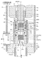
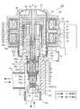
- the whole sectional view showing one embodiment of the flow control valve concerning the present invention The principal part sectional view showing the full closing state of the principal part in the flow control valve shown by FIG.
- the principal part sectional view showing the full open state (large flow control state) of the principal part in the flow control valve shown by FIG. The whole sectional view showing the modification (the 1) of the flow control valve shown by FIG.
- FIG. 1 is an overall cross-sectional view showing an embodiment of a flow control valve according to the present invention.
- the gap formed between the members, the separation distance between the members, and the like are large in comparison with the dimensions of the respective constituent members in order to facilitate understanding of the invention and for convenience in drawing. Or it may be drawn small.
- the flow control valve 1 of the illustrated embodiment is, for example, a motor-operated valve used to adjust the flow rate of the refrigerant in a heat pump type cooling and heating system etc., and the fluid (refrigerant) is introduced and derived similarly to the conventional flow control valve described above.
- Valve body 10 having a valve chamber 14 and a valve port (a large flow rate valve port) 16 with a valve seat 15 opened to the valve chamber 14, and a valve base 10 via a stepped cylindrical base 13
- a stepping motor (lifting / driving unit) 63 including a bottomed cylindrical can 30 fixed, a stator 40 externally fitted to the can 30, and a rotor 50 rotatably disposed on the inner periphery of the can 30, and a rotor Wonder planetary gear reduction mechanism 60 for reducing the number of rotations of 50 and the passing amount of fluid by controlling the valve seat 15 by contacting and separating (in other words, the fluid flowing through the valve port 16 according to the lift amount from the valve seat 15 Change the flow rate of Rotary motion of the two-stage valve body 32 provided with the sub-valve body (second valve body) 31 and the output gear 57 of the planetary gear reduction mechanism 60 into linear motion to convert the two-stage valve body 32 And a screw feed mechanism 27 for driving (raising and lowering).
- the valve main body 10 has a stepped thick disk-like sheet member 9 and a housing member 8 made of, for example, a sheet metal and having a long cylindrical shape (cylindrical shape with constant cross section).
- the lower end portion of the housing member 8 is joined to the bowl-like portion 9a by butt welding or the like, and a valve chamber 14 consisting of a cylindrical space is defined inside the housing member 8.
- a valve port (orifice) 16 consisting of a cylindrical surface that opens to the valve chamber 14 is formed vertically.
- a first inlet / outlet 11 consisting of a pipe fitting 11a is connected (by brazing or the like) to one side (the housing member 8) of the valve chamber 14 and to the bottom (the lower side of the valve port 16 of the sheet member 9). Is connected (by brazing or the like) to a second inlet / outlet 12 consisting of a pipe joint 12a. Further, the lower portion of the cylindrical holding member 19a of the support member 19 described later is inserted into the upper portion of the valve chamber 14 (in other words, the upper opening of the housing member 8), and caulked. ) (Clamping portion 13a).
- a stepped cylindrical base 13 (a peripheral step portion thereof) is joined to the upper end (upper opening) of the housing member 8 by welding or the like, and the upper end of the cylindrical base 13 is cylindrical with a lid.
- the lower end portion of the can 30 is hermetically joined by butt welding or the like.
- a support member for supporting a two-stage valve body 32 (a main valve body (first valve body) 29) and the like disposed in the internal space so as to be able to move up and down in the internal space defined by the valve body 10 and the can 30 19 are arranged fixed to the valve body 10.
- the support member 19 has a cylindrical holding member 19a with a partition 19c and a bearing member 19h with an internal thread 19i, and (the central portion of the cylindrical holding member 19a is press-fit and caulked inside the cylindrical base 13) The lower part of the cylindrical holding member 19a is inserted into the upper opening of the housing member 8 (with a slight gap).
- a stepped cylindrical bearing member 19 h having a female screw 19 i screwed downward to the inner peripheral surface is fixed to the upper portion of the cylindrical holding member 19 a by caulking or the like.
- a spring chamber 19d is defined between the partition wall 19c of the cylindrical holding member 19a and the bearing member 19h, and (the main valve body 29 of) the two-stage valve body 32 is always opened in the spring chamber 19d (upward direction).
- the valve-opening spring 26 which consists of a compression coiled spring urging
- the stator 40 mounted on the outer periphery of the can 30 comprises a yoke 41, a bobbin 42, a coil 43, a resin mold cover 44 and the like, and the rotor 50 rotatably supported within the can 30 (without moving up and down) is
- a cylindrical rotor member 51 made of a magnetic material and a sun gear member 52 made of a resin material are integrally connected.
- a shaft 62 is inserted into the central portion of the sun gear member 52, and the upper portion of the shaft 62 is supported by a support member 61 disposed inside the top of the can 30.
- the sun gear 53 of the sun gear member 52 meshes with a plurality of planet gears 55 rotatably supported by a shaft 56 provided on a carrier 54 mounted on the bottom surface of the output gear 57.
- the upper half of the planetary gear 55 meshes with an annular ring gear (internal gear fixed gear) 58 attached by caulking to the upper end of the cylindrical member 18 fixed to the upper portion of the cylindrical holding member 19a.
- the number of teeth of the ring gear 58 and the number of teeth of the internal gear 57a of the output gear 57 are slightly different, whereby the rotational speed of the sun gear 53 is reduced at a large reduction ratio and transmitted to the output gear 57. (A gear arrangement such as this is called a so-called strange planetary gear reduction mechanism 60).
- the output gear 57 is in sliding contact with the upper surface of the cylindrical bearing member 19 h, and the upper portion of the stepped cylindrical output shaft 59 is press-fitted at the center of the bottom of the output gear 57. Is rotatably inserted into a fitting insertion hole 19g formed in the upper half of the central portion of the bearing member 19h. The lower portion of the shaft 62 is fitted to the upper portion of the output shaft 59.
- An external thread 22i provided on a screw driving member (also referred to as a driver) 22 (an outer periphery of the bearing 22) is screwed with the internal thread 19i provided on (the inner circumference of) the bearing 19h. 22 converts the rotational movement of the output gear 57 (i.e., the rotor 50) into linear movement in the direction of the axis O (raising and lowering direction) by means of a screw feed mechanism 27 comprising an external thread 22i and an internal thread 19i.
- the output gear 57 is rotationally moved at a fixed position in the direction of the axis O without moving up and down, and is screw-driven in a slit-like fitting groove 59a provided in the lower portion of the output shaft 59 connected to the output gear 57.
- a flat driver-shaped plate-like portion 22a provided at the upper end of the member 22 is inserted to transmit the rotational movement of the output gear 57 to the screw drive member 22 side.
- the thrust transmission shaft 28 is slidably inserted from the top into the insertion hole formed in the large diameter upper portion 28a in which the stepped fitting hole is formed in the center and the partition wall 19c of the cylindrical holding member 19a.
- the upper half portion (a central hole 29v of the main valve body 29 formed of a stepped cylindrical body) which is composed of a body portion 28b and a small diameter lower portion 28c having a diameter slightly smaller than that of the intermediate body portion 28b.
- the hole 29d) is externally fitted and fixed by press-fitting or the like, and the main valve body 29 and the thrust transmission shaft 28 are integrally raised and lowered.
- the upper portion of the main valve body 29 (specifically, the upper large diameter fitting portion 29e slightly enlarged in diameter) connected to (the small diameter lower portion 28c of) the thrust transmission shaft 28 is a cylinder fixed inside the valve body 10 It is slidably inserted in the lower part of the holding member 19a and guided by the cylindrical holding member 19a to move in the direction of the axis O. That is, the lower inner periphery (inner peripheral portion below the partition wall 19c) of the cylindrical holding member 19a is a valve guide hole 19f for guiding the main valve 29 in the direction of the axis O (raising and lowering direction).
- the muffling member 71 is abutted against the muffling member 71 described later (of the main valve body 29).
- a convex surface 28d is provided for interpolative holding in the central hole 29v.
- the shape of the convex surface 28d can be set appropriately, but the contact area with the muffling member 71 (upper end face) is reduced (for example, as point contact) to secure the flow passage area at the upper end face of the muffling member 71 It is preferable to use a hemispherical surface, a semi-elliptical spherical surface, a truncated conical surface or the like.
- valve body guide hole 19f (specifically, the space 21 defined above the main valve body 29 in the valve body guide hole 19f, in other words, between the main valve body 29 and the partition wall 19c of the cylindrical holding member 19a
- the space 21) and the valve chamber 14 (and the valve port 16) are sliding clearances between the valve body guide hole 19f and the main valve body 29 (the upper large diameter fitting portion 29e thereof). It is always in communication via
- valve opening spring 26 disposed in the spring chamber 19 d above the partition wall 19 c of the cylindrical holding member 19 a is disposed with its lower end in contact with the partition wall 19 c.
- a pulling-up spring receiver 20 having hook-shaped hooks 20a and 20b vertically is disposed.
- the upper hooking portion 20 a of the pull-up spring receiver 20 is placed on the upper portion of the valve opening spring 26, and the lower hooking portion 20 b is hooked on the lower end step portion of the large diameter upper portion 28 a of the thrust transmission shaft 28.
- the cylindrical holding member 19a is formed with a communication hole 19e which is a horizontal hole communicating the spring chamber 19d with the inside of the can 30.
- the lower portion of the main valve body 29 connected to the thrust transmission shaft 28 is disposed so as to be able to move up and down in the valve chamber 14 and to surround the outer periphery of the lower end portion of the main valve body 29.
- a substantially concave secondary valve body (second valve body) 31 is slidably extrapolated.
- the portion is a fitting hole 29d in which the small diameter lower portion 28c of the thrust transmission shaft 28 is fitted and fixed, and it is oriented horizontally (from the middle of the central hole 29v (directly below the fitting hole 29d)
- a plurality of relatively small diameter side holes 29 u are formed in the direction perpendicular to the direction).
- the lower end portion of the central hole 29v is slightly reduced in diameter, and the inner peripheral surface (cylindrical surface) of the lower end reduced diameter portion is an upper valve body portion 37c formed on the upper end portion of the sub valve body 31 described later. ) Is a valve port (small flow rate valve port) 29c with a valve seat 29b which is opened and closed.
- the upper half (upper opening) of the central hole 29v of the main valve body 29 is closed by the small diameter lower portion 28c of the thrust transmission shaft 28, and the lower half of the central hole 29v (thrust transmission shaft 28
- a communication passage (upper communication passage) 33a communicating with the communication space 34 consisting of the space defined by the valve body 31 and the space defined around the lower end of the main valve body 29 and the valve chamber 14 is formed.
- the outer periphery of the lower end portion of the main valve body 29 (the outer periphery immediately below the horizontal hole 29u) is widened, and the upper surface of the widened portion 29f faces inward at the upper end portion of the interlocking member 36 of the sub valve body 31 described later.
- the auxiliary valve body 31 disposed on the outer periphery of the lower end portion of the main valve body 29 has a cylindrical interlocking member 36 slidably inserted on the lower end portion (widening portion 29f) of the main valve body 29;
- a stepped valve body member 37 connected to the lower end opening of the interlocking member 36 and defined around the lower end portion of the main valve body 29 by (the interlocking member 36 and the valve body member 37) of the sub valve body 31
- the space is defined as the communication space 34.
- the main valve body 29 (the hook-like locking portion 29g provided on the wide portion 29f) is retained and locked, and the main valve body 29 is opened (a predetermined gap is opened)
- An inner hook-shaped locking portion 36g which defines a through hole to be inserted is protruded inward.
- a communication space 34 and a communication space 34 are provided between the wide portion 29 f of the main valve body 29 and the interlocking member 36 of the sub valve body 31 (specifically, an annular groove formed on the outer periphery of the wide portion 29 f of the main valve body 29).
- An O-ring 38 is mounted as a sealing member for airtightly sealing the space between the valve chamber 14 and the sliding space between the wide portion 29 f of the main valve body 29 and the interlocking member 36 of the sub valve body 31. .
- the lower end portion of the interlocking member 36 is fixed to the lower outer periphery (the outer periphery of the lower large diameter portion 37a) of the valve body member 37 by press fitting, caulking, welding or the like.
- the inner diameter of the inner hook-shaped locking portion 36g of the interlocking member 36 (the inner diameter of the through hole defined by the inner hook-shaped locking portion 36g) is the upper large diameter of the main valve body 29 in consideration of the assemblability. The diameter is larger than the outer diameter of the fitting portion 29e.
- the valve body member 37 provided at the lower part of the interlocking member 36 basically has a lower large diameter part 37a larger in diameter and thicker than the valve port (large flow rate valve port) 16, and the lower large diameter part 37a.
- An upper small diameter portion 37b having a diameter slightly larger than the central hole 29v of the main valve body 29 is formed on the upper side.
- the lower end face of (the lower large diameter portion 37a of) the valve body member 37 is a lower valve body portion (a large flow rate formed by an inverted frusto-conical surface that opens and closes the valve port 16 by coming into contact with and separating from the valve seat Valve body portion 37d.
- a stepped central hole (longitudinal hole) having a relatively large diameter in the vertical direction (axis O direction) from the center of the lower end surface of the lower large diameter portion 37a to the upper end surface near the upper small diameter portion 37b.
- a 37v is formed, and a plurality of relatively small diameter side holes 37u are formed laterally from the upper portion of the center hole 37v (the middle part of the upper small diameter portion 37b).
- the central hole 37v and the lateral hole 37u form a communication passage (lower communication passage) 33b for always communicating the valve port 16 with the communication space 34.
- the central hole (vertical hole) 37v is configured in three stages of a lower diameter enlarged portion 37e, an intermediate intermediate diameter portion 37f, and an upper diameter reduced portion 37g from the lower side, and the intermediate intermediate diameter portion Reference numeral 37f denotes a cylindrical storage hole into which a noise reduction member 72 described later is fitted, and the lateral reduction hole 37u is connected to the upper reduced diameter portion 37g.
- a substantially truncated cone-shaped projecting surface is formed on the upper end surface of (the upper small diameter portion 37b of) the valve body member 37, and the projecting surface (in particular, the side portion of the projecting surface) is the main valve body
- the communication passage (lower communication passage) 33 b provided in (the valve material member 37 of) the above-mentioned sub valve body 31 and the space formed between the main valve body 29 and the sub valve body 31
- a small flow passage 35 communicating the valve port 16 with the valve chamber 14 is formed (in the two-stage valve body 32) by the communication space 34 and the communication path (upper communication path) 33a provided in the main valve body 29.
- a valve port (small flow rate valve port) 29c with a valve seat 29d is formed which is opened and closed by an upper valve body portion 37c formed on the upper end surface of the upper small diameter portion 37b of the body member 37. Then, the flow rate (passage amount) of the fluid flowing through the valve port 29 c in the small flow rate passage 35 according to the lift amount of the upper valve body portion 37 c of the sub valve body 31 from the valve seat 29 d (that is, the separation amount in the vertical direction) It is supposed to be changed (more on this later).
- the hook-shaped locking portion 29g provided on (the widened portion 29f of the main valve body 29) and the inner hook-shaped locking portion 36g provided on (the interlocking member 36) of the sub valve body 31 When the valve port 29c is closed by the upper valve body portion 37c of the body 31 (in other words, when the upper valve body portion 37c of the valve body 31 is seated on the valve seat 29b), predetermined in the axis O direction (vertical direction) It is set to have a gap La of dimensions (described in detail later).
- the upper spring receiving portion 29h formed of an annular lower surface of the widened portion 29f and the valve body member 37
- the sub valve body 31 is always attached in the valve closing direction (downward) between the lower spring receiving portion 37h which is an annular step surface formed between the lower large diameter portion 37a and the upper small diameter portion 37b.
- a valve closing spring (biasing member) 39 formed of a compression coil spring is compressed.
- the communication passage (upper communication passage) 33a of the main valve body 29 constituting the small flow passage 35 is provided.
- a substantially cylindrical silencer member (valve communication member (valve chamber 14 muffling member) 71) is provided, and a communication passage (lower communication passage) 33b of the valve member 37 of the sub valve body 31
- a mouth 16 side muffling member) 72 is provided.
- the muffling member 71 is formed to have substantially the same diameter as the central hole (longitudinal hole) 29v in the communication passage 33a, and is positioned below (directly below) the horizontal hole 29u in the central hole 29v and along the central hole 29v. It is internally fitted.
- the muffling member 71 has a lower portion of the central hole 29v by abutment of a convex surface 28d provided at the lower end portion of the small diameter lower portion 28c of the thrust transmission shaft 28 fitted in the fitting hole 29d (at the center of the upper end surface thereof).
- the inner peripheral step portion 29a provided on the inner side is slightly pressed and held and fixed. That is, the muffling member 71 is disposed in (the central hole 29v of) the communication passage 33a in a posture in which the upper and lower end surfaces thereof are not closed by the flow passage wall (inner wall) of the communication passage 33a.
- the muffling member 72 is formed to have approximately the same diameter as the middle middle diameter portion 37f of the central hole (vertical hole) 37v in the communication passage 33b, and is fitted inside along the middle middle diameter portion 37f and caulked (see FIG. In the illustrated example, the lower end portion of the middle intermediate diameter portion 37f is held and fixed by caulking inward. That is, the muffling member 72 is disposed in (the central hole 37v of) the communication passage 33b in a posture in which the upper and lower end surfaces thereof are not closed by the flow passage wall (inner wall) of the communication passage 33b.
- plate-like metal meshes are laminated and formed into a cylindrical shape, plate-like metal mesh is wound into a columnar shape, or sheet-like It is possible to use one obtained by die-cutting a porous body or a granular sintered body into a cylindrical shape.
- the lamination direction is the formation direction of the central hole 29v of the communication passage 33a and the central hole 37v of the communication passage 33b ( It is disposed along the vertical direction (that is, the flow direction of the fluid in the communication passage 33a and the communication passage 33b).
- the die-cutting (punching) direction is the center hole 29v of the communication passage 33a or the center of the communication passage 33b.
- the holes 37v are arranged along the formation direction (vertical direction) (that is, the flow direction of the fluid in the communication passage 33a and the communication passage 33b).
- the fixing method and the like of the sound deadening members 71 and 72 are not limited to the illustrated example.
- the sound deadening members 71 and 72 are cylindrical, for example, if the cross-sectional shape of the central holes 29 v and 37 v is polygonal (for example, hexagonal), the sound deadening members 71 and 72 are polygonal columnar (for example, hexagonal ) May be used. Furthermore, the sound deadening members 71 and 72 may be columnar in the state of being disposed in the communication passages 33a and 33b. For example, the punched sheets may be stacked in the communication passages 33a and 33b to be columnar.
- the bore diameter D2 of the valve port 16 and the pressure receiving diameter of the sub valve body 31 mounted on the main valve body 29 (a diameter which receives pressure from the fluid in the valve chamber 14,
- the inner diameter of the stop portion 36g) ⁇ D1 is set to be substantially the same.
- the fluid (refrigerant) is bidirectional (in the direction from the first inlet / outlet 11 to the second inlet / outlet 12 (horizontal ⁇ down)), and from the second inlet / outlet 12 to the first inlet / outlet 11 Flow in both directions (down and sideways), and the amount of rotation of the rotor 45 of the stepping motor 63 mounted above the valve body 10 is controlled to make the two-stage valve body 32 By changing the lift amount L of (the main valve body 29), the flow rate of the fluid (refrigerant) is adjusted.
- the upper valve body portion 37c of (the valve body member 37 of) the sub valve body 31 is the main valve body 29.
- the valve seat 29b is press-contacted (seated) to close the valve port 29c, and the lower valve body portion 37d of (the valve member 37 of the sub valve body 31) is press-contacted (seated) to the valve seat 15 of the valve main body 10
- the valve port 16 is closed.
- the bore diameter DD2 of the valve port 16 and the pressure receiving diameter DD1 of the sub valve body 31 are substantially equal, and therefore the sub valve body 31 acts in this valve closed state.
- the push-up force (the force in the valve opening direction) and the push-down force (the force in the valve closing direction) are balanced (the differential pressure is canceled).
- the force in the valve closing direction acting on the sub valve body 31 is equal to or greater than the force in the valve opening direction. In this case, the sub valve body 31 can be prevented from being pushed up by the fluid pressure.
- the lower end portion of the main valve body 29 is in a state where the lower valve body portion 37b of the body 31 (the valve body member 37) is in pressure contact (seated) with the valve seat 15 of the valve body 10 by (the biasing force)
- the main valve body 29 is moved (raised) to slide in the interlocking member 36 of the sub valve body 31, and the upper valve body portion 37 c of (the valve body member 37 of) the sub valve body 31 is the main valve body 29.
- the valve port 29c is opened apart from the valve seat 29b.
- the fluid that has flowed in from the second inlet / outlet 12 (the valve port 16 of the second port 12) is communicated with the communication passage (lower communication passage) 33a (center hole 37v, lateral hole 37u) of the valve member 37 of the sub valve body 31 ⁇ communication space 34 ⁇ sub
- the communication passage (lower communication passage) 33a center hole 37v, lateral hole 37u) of the valve member 37 of the sub valve body 31 ⁇ communication space 34 ⁇ sub
- the flow rate of the fluid flowing into the valve chamber 14 (that is, the fluid flowing out to the first inlet / outlet 11) gradually increases as the main valve body 29 rises.
- the muffling member 72 is fitted in the center hole 37v of the communication passage 33b of the valve member 37 of the sub valve body 31 along the center hole 37v, and the center hole 29v of the communication passage 33a of the main valve body 29. Since the muffling member 71 is internally fitted along the central hole 29v, the fluid flowing in from the second inlet / outlet 12 is transferred to the central hole 37v of the communication passage 33b of the valve member 37 of the sub valve body 31.
- the muffling member 71 is directed from the lower end face to the upper end face when passing through the central hole 29v of the communication passage 33a of the main valve body 29.
- the fluid flowing in from the second inlet / outlet 12 is a bubble in the fluid by the two silencing members 72 and 71 disposed on the upstream side (valve port 16 side) and the downstream side (valve chamber 14 side) of the valve port 29c.
- the valve chamber 14 (first inlet / outlet 11) is to be passed through in a state where it is disassembled and subdivided. Therefore, in the small flow rate control area (area where noise is likely to occur), the noise when passing the fluid (refrigerant) is reliably reduced.
- the lower valve body portion 37b of (the valve body member 37 of) the sub valve body 31 is separated from the valve seat 15 of the valve body 10, and the sub valve body 31
- the fluid that has flowed into (the valve port 16 of) the second inlet / outlet 12 passes through the gap between the lower valve body portion 37 b of the sub valve body 31 (the valve body member 37) and the valve seat 15 of the valve body 10.
- the flow rate of the fluid flowing into the chamber 14 and flowing into the valve chamber 14 gradually increases as the main valve body 29 (and the sub valve body 31) ascends.
- (most part of) the fluid which has flowed in from (the valve port 16 of) the second inlet / outlet 12 is the lower valve body portion 37b of the sub valve body 31 (the valve body member 37) and the valve seat 15 of the valve body 10.
- the lower end portion of the main valve body 29 is defined by the communication passage (upper communication passage) 33 a provided in the main valve body 29 and the sub valve body 31.
- a small flow passage 35 communicating the valve chamber 14 with the valve port 16 via the communication space 34 and the communication passage (lower communication passage) 33 b provided in the sub valve body 31 (in the two-stage valve body 32 Mufflers 71, 72 for dividing air bubbles in the fluid are internally fitted in the communication passage (upper communication passage) 33a and the communication passage (lower communication passage) 33b which are formed and which constitute the small flow rate passage 35.
- the opening degree (small flow rate) of the fluid (refrigerant), in particular, is small. Noise during the passage of fluid (refrigerant) in the control Pressure loss is suppressed in a large flow control) region.
- the fluid in the small flow rate passage 35 provided in the two-stage valve body 32 is from one end face of the cylindrical silencer members 71 and 72 internally fitted in the small flow rate passage 35 (through the inside thereof) Since it is made to flow through the other end face, for example, the pressure loss can be reduced while the cost of parts can be reduced, as compared with the conventional one in which the fluid flows through the side face of the cylindrical muffling member. The flow rate can be obtained.
- the diameter ⁇ D2 of the valve port 16 and the pressure receiving diameter ⁇ D1 of the sub valve body 31 are equalized, and the force acting in the moving direction (raising and lowering direction) of the sub valve body 31 in the closed state or small flow control state is balanced (difference Since the pressure is canceled), the controllability in the small opening area (low flow area) at the time of flow control, particularly when the fluid flows in the direction from the valve port 16 toward the valve chamber 14, is improved at the time of flow control.
- the diameter ⁇ D2 of the valve port 16 and the pressure receiving diameter ⁇ D1 of the sub valve body 31 are equalized, and the force acting in the moving direction (raising and lowering direction) of the sub valve body 31 in the closed state or small flow control state is balanced (difference Because the pressure is canceled), the load acting on the valve body (two-stage valve body 32 in the large flow rate control state) at the time of flow control can be reduced as much as possible, and the drive torque of the valve body can be reduced.
- miniaturization and power saving can be achieved.
- the main valve body is a valve body which is moved up and down by (the driving force of) the stepping motor 63 and changes the flow rate of the fluid flowing through the valve port (large flow rate valve port) 16 according to the lift amount.
- the small flow rate passage 35 provided in the two-stage valve body 32 is formed by the relative movement of the main valve body 29 and the sub-valve body 31 (in the vertical direction).
- valve body 32 is configured in one piece, and the valve port 29c formed in the small flow rate passage 35 provided in the valve body 32 is opened and closed. Without controlling the flow rate of the fluid flowing through the valve port 29c (ie, the valve chamber 4 and the valve port 16 are constantly communicated via the small flow rate passage 35 (the valve port 29c of the valve flow), and the valve body 32 controls only the flow rate of the fluid flowing through the valve port 16 (large flow rate control)
- the present invention can also be applied to valves.
- the horizontal hole 29u connected to the valve chamber 14 the central hole (vertical hole) 29v connected to the horizontal hole 29u, and the central hole (vertical hole) 37v (lower enlarged diameter portion 37e, middle intermediate diameter portion 37f, upper reduced diameter portion connected to the valve port 16).
- a small flow passage 35 is formed in the valve body 32, and a valve port 29c is formed between the central hole 29v and the central hole 37v.
- a cylindrical muffling member 71 having substantially the same diameter as the central hole 29v is internally fitted below (below) the lateral hole 29u in the central hole 29v, and the middle middle diameter portion 37f of the central hole 37v is in the middle
- a cylindrical muffling member 72 having substantially the same diameter as the diameter portion 37f is internally fitted.
- the spring chamber 19d and the space 21 are separated by the partition wall 19c of the cylindrical holding member 19a of the support member 19.
- the partition length may be omitted to shorten the vertical length.
- symbol is attached
- the planetary gear reduction mechanism 60 for reducing the rotational speed of the rotor 50 may be omitted to move the valve body up and down.
- the valve closing spring (biasing member) 39 is attached in the two-stage valve body 32. It is needless to say that the two-stage valve body 32 may be seated on the valve seat 15 or separated from the valve seat 15 mainly by the fluid pressure.
- the fluid in the small flow passage 35 flows only through both end faces (upper end face and lower end face) of the substantially cylindrical silencer members 71 and 72. If the cylindrical muffling members 71 and 72 flow from one end face (through the inside thereof) through the other end face, a part of the fluid in the small flow rate passage 35 is made of the muffling members 71 and 72. It may be made to flow through a part of the side.
- valve shaft is vertically moved (moved) using a stepping motor or the like having a stator and a rotor as described in the above embodiment, and the lift amount (valve opening degree) is arbitrarily finely adjusted.
- the present invention can also be applied to an electromagnetic flow control (switching) valve using, for example, a solenoid or the like other than the electric flow control valve.
Landscapes
- Engineering & Computer Science (AREA)
- General Engineering & Computer Science (AREA)
- Mechanical Engineering (AREA)
- Lift Valve (AREA)
- Details Of Valves (AREA)
- Electrically Driven Valve-Operating Means (AREA)
Applications Claiming Priority (2)
| Application Number | Priority Date | Filing Date | Title |
|---|---|---|---|
| JP2018010246A JP2019128001A (ja) | 2018-01-25 | 2018-01-25 | 流量調整弁 |
| JP2018-010246 | 2018-01-25 |
Publications (1)
| Publication Number | Publication Date |
|---|---|
| WO2019146345A1 true WO2019146345A1 (ja) | 2019-08-01 |
Family
ID=67395846
Family Applications (1)
| Application Number | Title | Priority Date | Filing Date |
|---|---|---|---|
| PCT/JP2018/047522 Ceased WO2019146345A1 (ja) | 2018-01-25 | 2018-12-25 | 流量調整弁 |
Country Status (2)
| Country | Link |
|---|---|
| JP (1) | JP2019128001A (enExample) |
| WO (1) | WO2019146345A1 (enExample) |
Cited By (1)
| Publication number | Priority date | Publication date | Assignee | Title |
|---|---|---|---|---|
| CN114635975A (zh) * | 2020-12-15 | 2022-06-17 | 株式会社鹭宫制作所 | 电动阀 |
Families Citing this family (2)
| Publication number | Priority date | Publication date | Assignee | Title |
|---|---|---|---|---|
| JP2021110450A (ja) * | 2020-01-10 | 2021-08-02 | 株式会社不二工機 | 電動弁 |
| JP7361628B2 (ja) * | 2020-02-19 | 2023-10-16 | 株式会社鷺宮製作所 | 電動弁及び冷凍サイクルシステム |
Citations (9)
| Publication number | Priority date | Publication date | Assignee | Title |
|---|---|---|---|---|
| JPS5214925A (en) * | 1975-07-25 | 1977-02-04 | Sulzer Ag | Valve conbination device having two valve and it*s independent driveidevices |
| JP2000009245A (ja) * | 1998-06-25 | 2000-01-11 | Denso Corp | 電磁弁 |
| JP2002310540A (ja) * | 2001-04-12 | 2002-10-23 | Saginomiya Seisakusho Inc | 絞り装置および空気調和機 |
| JP2005003114A (ja) * | 2003-06-12 | 2005-01-06 | Fuji Koki Corp | 電磁弁 |
| JP2005024161A (ja) * | 2003-07-01 | 2005-01-27 | Fuji Koki Corp | 電磁弁 |
| JP2005061694A (ja) * | 2003-08-08 | 2005-03-10 | Daikin Ind Ltd | 冷媒制御弁 |
| JP2007024186A (ja) * | 2005-07-15 | 2007-02-01 | Saginomiya Seisakusho Inc | 2段式制御弁 |
| JP2017211032A (ja) * | 2016-05-26 | 2017-11-30 | 株式会社不二工機 | 流量調整弁 |
| JP2017211034A (ja) * | 2016-05-26 | 2017-11-30 | 株式会社不二工機 | 流量調整弁 |
-
2018
- 2018-01-25 JP JP2018010246A patent/JP2019128001A/ja active Pending
- 2018-12-25 WO PCT/JP2018/047522 patent/WO2019146345A1/ja not_active Ceased
Patent Citations (9)
| Publication number | Priority date | Publication date | Assignee | Title |
|---|---|---|---|---|
| JPS5214925A (en) * | 1975-07-25 | 1977-02-04 | Sulzer Ag | Valve conbination device having two valve and it*s independent driveidevices |
| JP2000009245A (ja) * | 1998-06-25 | 2000-01-11 | Denso Corp | 電磁弁 |
| JP2002310540A (ja) * | 2001-04-12 | 2002-10-23 | Saginomiya Seisakusho Inc | 絞り装置および空気調和機 |
| JP2005003114A (ja) * | 2003-06-12 | 2005-01-06 | Fuji Koki Corp | 電磁弁 |
| JP2005024161A (ja) * | 2003-07-01 | 2005-01-27 | Fuji Koki Corp | 電磁弁 |
| JP2005061694A (ja) * | 2003-08-08 | 2005-03-10 | Daikin Ind Ltd | 冷媒制御弁 |
| JP2007024186A (ja) * | 2005-07-15 | 2007-02-01 | Saginomiya Seisakusho Inc | 2段式制御弁 |
| JP2017211032A (ja) * | 2016-05-26 | 2017-11-30 | 株式会社不二工機 | 流量調整弁 |
| JP2017211034A (ja) * | 2016-05-26 | 2017-11-30 | 株式会社不二工機 | 流量調整弁 |
Cited By (2)
| Publication number | Priority date | Publication date | Assignee | Title |
|---|---|---|---|---|
| CN114635975A (zh) * | 2020-12-15 | 2022-06-17 | 株式会社鹭宫制作所 | 电动阀 |
| CN114635975B (zh) * | 2020-12-15 | 2024-04-16 | 株式会社鹭宫制作所 | 电动阀 |
Also Published As
| Publication number | Publication date |
|---|---|
| JP2019128001A (ja) | 2019-08-01 |
Similar Documents
| Publication | Publication Date | Title |
|---|---|---|
| JP6505151B2 (ja) | 流量調整弁 | |
| JP6692215B2 (ja) | 流量調整弁 | |
| JP6302717B2 (ja) | 電動弁 | |
| KR102408887B1 (ko) | 전기 밸브 | |
| JP6745141B2 (ja) | 流量調整弁 | |
| CN106168304B (zh) | 电动阀 | |
| JP2021516319A (ja) | 電子膨張弁 | |
| JP2013130271A (ja) | 電動弁 | |
| JP2014081046A (ja) | 流量制御弁 | |
| JP6709926B1 (ja) | 電動弁 | |
| JP6715879B2 (ja) | 三方切換弁 | |
| JP6850364B2 (ja) | 電子膨張弁及それを具備する冷凍システム | |
| JP6478958B2 (ja) | 制御弁 | |
| KR102046664B1 (ko) | 가변 용량 압축기용 제어 밸브 | |
| JP2015094372A (ja) | 電動弁 | |
| JP2017129212A (ja) | 流量調整弁 | |
| JP2019128001A (ja) | 流量調整弁 | |
| JP2015086996A (ja) | 電気的駆動弁 | |
| JP7333045B2 (ja) | 流量制御弁 | |
| JP2017194167A (ja) | 流量制御弁 | |
| JP6585380B2 (ja) | 電動弁 | |
| CN115013539A (zh) | 一种全流通电子膨胀阀 | |
| US20060124182A1 (en) | Angled fluid control valve seal | |
| JP3771577B1 (ja) | パイロット電磁弁 | |
| JP2013113361A (ja) | 電動弁 |
Legal Events
| Date | Code | Title | Description |
|---|---|---|---|
| 121 | Ep: the epo has been informed by wipo that ep was designated in this application |
Ref document number: 18902216 Country of ref document: EP Kind code of ref document: A1 |
|
| NENP | Non-entry into the national phase |
Ref country code: DE |
|
| 122 | Ep: pct application non-entry in european phase |
Ref document number: 18902216 Country of ref document: EP Kind code of ref document: A1 |