WO2019145997A1 - 直流給電システム - Google Patents
直流給電システム Download PDFInfo
- Publication number
- WO2019145997A1 WO2019145997A1 PCT/JP2018/001973 JP2018001973W WO2019145997A1 WO 2019145997 A1 WO2019145997 A1 WO 2019145997A1 JP 2018001973 W JP2018001973 W JP 2018001973W WO 2019145997 A1 WO2019145997 A1 WO 2019145997A1
- Authority
- WO
- WIPO (PCT)
- Prior art keywords
- voltage
- power
- bus
- current
- storage battery
- Prior art date
- Legal status (The legal status is an assumption and is not a legal conclusion. Google has not performed a legal analysis and makes no representation as to the accuracy of the status listed.)
- Ceased
Links
Images


Classifications
-
- H—ELECTRICITY
- H02—GENERATION; CONVERSION OR DISTRIBUTION OF ELECTRIC POWER
- H02J—ELECTRIC POWER NETWORKS; CIRCUIT ARRANGEMENTS OR SYSTEMS FOR SUPPLYING OR DISTRIBUTING ELECTRIC POWER; SYSTEMS FOR STORING ELECTRIC ENERGY
- H02J1/00—Circuit arrangements for DC mains or DC distribution networks
- H02J1/10—Parallel operation of DC sources
- H02J1/102—Parallel operation of DC sources being switching converters
-
- H—ELECTRICITY
- H02—GENERATION; CONVERSION OR DISTRIBUTION OF ELECTRIC POWER
- H02J—ELECTRIC POWER NETWORKS; CIRCUIT ARRANGEMENTS OR SYSTEMS FOR SUPPLYING OR DISTRIBUTING ELECTRIC POWER; SYSTEMS FOR STORING ELECTRIC ENERGY
- H02J1/00—Circuit arrangements for DC mains or DC distribution networks
-
- H—ELECTRICITY
- H02—GENERATION; CONVERSION OR DISTRIBUTION OF ELECTRIC POWER
- H02J—ELECTRIC POWER NETWORKS; CIRCUIT ARRANGEMENTS OR SYSTEMS FOR SUPPLYING OR DISTRIBUTING ELECTRIC POWER; SYSTEMS FOR STORING ELECTRIC ENERGY
- H02J3/00—Circuit arrangements for AC mains or AC distribution networks
- H02J3/38—Arrangements for feeding a single network from two or more generators or sources in parallel; Arrangements for feeding already energised networks from additional generators or sources in parallel
-
- H—ELECTRICITY
- H02—GENERATION; CONVERSION OR DISTRIBUTION OF ELECTRIC POWER
- H02J—ELECTRIC POWER NETWORKS; CIRCUIT ARRANGEMENTS OR SYSTEMS FOR SUPPLYING OR DISTRIBUTING ELECTRIC POWER; SYSTEMS FOR STORING ELECTRIC ENERGY
- H02J7/00—Circuit arrangements for charging or discharging batteries or for supplying loads from batteries
- H02J7/50—Circuit arrangements for charging or discharging batteries or for supplying loads from batteries acting upon multiple batteries simultaneously or sequentially
- H02J7/52—Circuit arrangements for charging or discharging batteries or for supplying loads from batteries acting upon multiple batteries simultaneously or sequentially for charge balancing, e.g. equalisation of charge between batteries
- H02J7/56—Active balancing, e.g. using capacitor-based, inductor-based or DC-DC converters
-
- H—ELECTRICITY
- H02—GENERATION; CONVERSION OR DISTRIBUTION OF ELECTRIC POWER
- H02J—ELECTRIC POWER NETWORKS; CIRCUIT ARRANGEMENTS OR SYSTEMS FOR SUPPLYING OR DISTRIBUTING ELECTRIC POWER; SYSTEMS FOR STORING ELECTRIC ENERGY
- H02J7/00—Circuit arrangements for charging or discharging batteries or for supplying loads from batteries
- H02J7/90—Regulation of charging or discharging current or voltage
- H02J7/94—Regulation of charging or discharging current or voltage in response to battery current
-
- H—ELECTRICITY
- H02—GENERATION; CONVERSION OR DISTRIBUTION OF ELECTRIC POWER
- H02J—ELECTRIC POWER NETWORKS; CIRCUIT ARRANGEMENTS OR SYSTEMS FOR SUPPLYING OR DISTRIBUTING ELECTRIC POWER; SYSTEMS FOR STORING ELECTRIC ENERGY
- H02J2101/00—Supply or distribution of decentralised, dispersed or local electric power generation
- H02J2101/20—Dispersed power generation using renewable energy sources
- H02J2101/22—Solar energy
-
- H—ELECTRICITY
- H02—GENERATION; CONVERSION OR DISTRIBUTION OF ELECTRIC POWER
- H02J—ELECTRIC POWER NETWORKS; CIRCUIT ARRANGEMENTS OR SYSTEMS FOR SUPPLYING OR DISTRIBUTING ELECTRIC POWER; SYSTEMS FOR STORING ELECTRIC ENERGY
- H02J2101/00—Supply or distribution of decentralised, dispersed or local electric power generation
- H02J2101/20—Dispersed power generation using renewable energy sources
- H02J2101/22—Solar energy
- H02J2101/24—Photovoltaics
-
- H—ELECTRICITY
- H02—GENERATION; CONVERSION OR DISTRIBUTION OF ELECTRIC POWER
- H02J—ELECTRIC POWER NETWORKS; CIRCUIT ARRANGEMENTS OR SYSTEMS FOR SUPPLYING OR DISTRIBUTING ELECTRIC POWER; SYSTEMS FOR STORING ELECTRIC ENERGY
- H02J2101/00—Supply or distribution of decentralised, dispersed or local electric power generation
- H02J2101/20—Dispersed power generation using renewable energy sources
- H02J2101/28—Wind energy
-
- H—ELECTRICITY
- H02—GENERATION; CONVERSION OR DISTRIBUTION OF ELECTRIC POWER
- H02J—ELECTRIC POWER NETWORKS; CIRCUIT ARRANGEMENTS OR SYSTEMS FOR SUPPLYING OR DISTRIBUTING ELECTRIC POWER; SYSTEMS FOR STORING ELECTRIC ENERGY
- H02J2101/00—Supply or distribution of decentralised, dispersed or local electric power generation
- H02J2101/20—Dispersed power generation using renewable energy sources
- H02J2101/30—Fuel cells
-
- H—ELECTRICITY
- H02—GENERATION; CONVERSION OR DISTRIBUTION OF ELECTRIC POWER
- H02J—ELECTRIC POWER NETWORKS; CIRCUIT ARRANGEMENTS OR SYSTEMS FOR SUPPLYING OR DISTRIBUTING ELECTRIC POWER; SYSTEMS FOR STORING ELECTRIC ENERGY
- H02J2207/00—Details of circuit arrangements for charging or discharging batteries or supplying loads from batteries
- H02J2207/20—Charging or discharging characterised by the power electronics converter
-
- H—ELECTRICITY
- H02—GENERATION; CONVERSION OR DISTRIBUTION OF ELECTRIC POWER
- H02J—ELECTRIC POWER NETWORKS; CIRCUIT ARRANGEMENTS OR SYSTEMS FOR SUPPLYING OR DISTRIBUTING ELECTRIC POWER; SYSTEMS FOR STORING ELECTRIC ENERGY
- H02J7/00—Circuit arrangements for charging or discharging batteries or for supplying loads from batteries
- H02J7/34—Parallel operation in networks using both storage and other DC sources, e.g. providing buffering
-
- H—ELECTRICITY
- H02—GENERATION; CONVERSION OR DISTRIBUTION OF ELECTRIC POWER
- H02J—ELECTRIC POWER NETWORKS; CIRCUIT ARRANGEMENTS OR SYSTEMS FOR SUPPLYING OR DISTRIBUTING ELECTRIC POWER; SYSTEMS FOR STORING ELECTRIC ENERGY
- H02J9/00—Circuit arrangements for emergency or stand-by power supply, e.g. for emergency lighting
- H02J9/04—Circuit arrangements for emergency or stand-by power supply, e.g. for emergency lighting in which the distribution system is disconnected from the normal source and connected to a standby source
- H02J9/06—Circuit arrangements for emergency or stand-by power supply, e.g. for emergency lighting in which the distribution system is disconnected from the normal source and connected to a standby source with automatic change-over, e.g. UPS systems
- H02J9/061—Circuit arrangements for emergency or stand-by power supply, e.g. for emergency lighting in which the distribution system is disconnected from the normal source and connected to a standby source with automatic change-over, e.g. UPS systems for DC powered loads
-
- Y—GENERAL TAGGING OF NEW TECHNOLOGICAL DEVELOPMENTS; GENERAL TAGGING OF CROSS-SECTIONAL TECHNOLOGIES SPANNING OVER SEVERAL SECTIONS OF THE IPC; TECHNICAL SUBJECTS COVERED BY FORMER USPC CROSS-REFERENCE ART COLLECTIONS [XRACs] AND DIGESTS
- Y02—TECHNOLOGIES OR APPLICATIONS FOR MITIGATION OR ADAPTATION AGAINST CLIMATE CHANGE
- Y02E—REDUCTION OF GREENHOUSE GAS [GHG] EMISSIONS, RELATED TO ENERGY GENERATION, TRANSMISSION OR DISTRIBUTION
- Y02E10/00—Energy generation through renewable energy sources
- Y02E10/50—Photovoltaic [PV] energy
- Y02E10/56—Power conversion systems, e.g. maximum power point trackers
Definitions
- the present invention relates to a stand-alone DC power supply system not connected with a commercial power supply.
- the DC power supply system includes a distributed power supply (for example, a device such as a solar power generator, a wind power generator, and a fuel cell), a DC bus connecting the distributed power supply to a load, and a plurality of DC power supplies (including storage batteries). And a converter (for example, a bidirectional DC / DC converter) for connecting a plurality of DC power devices to a DC bus, and a controller for controlling the plurality of converters.
- a distributed power supply for example, a device such as a solar power generator, a wind power generator, and a fuel cell
- a DC bus connecting the distributed power supply to a load
- a plurality of DC power supplies including storage batteries
- a converter for example, a bidirectional DC / DC converter
- the load (DC voltage) connected to the DC bus can be stabilized because the DC bus voltage (DC voltage) can be stabilized even if the DC voltage output from the distributed power supply to the DC bus is large. It is possible to supply a stable output voltage (DC voltage) to
- a direct current bus serving as a bus bar of direct current feed, a power generation device, a first converter for supplying generated power of the power generation device to the direct current bus, and the direct current It is connected between the second converter, which converts the DC voltage supplied to the bus to supply the load device, a plurality of storage batteries, each of the plurality of storage batteries, and the DC bus, to the DC bus
- a plurality of bi-directional converters which bi-directionally perform voltage conversion between the supplied DC voltage and the DC voltage of the storage battery to supply DC current from the DC bus to the storage battery or from the storage battery to the DC bus; When the generated power exceeds the load power, the generated power of the power generation device is compared with the load power supplied from the second converter to the load device.
- the control unit applies the first voltage-current characteristic in which the slope increases as the remaining battery capacity of the corresponding storage battery increases, with respect to each bidirectional converter.
- the second voltage-current characteristic is provided in which the absolute value of the slope decreases as the remaining battery capacity of the storage battery increases.
- a storage battery having a larger remaining battery capacity than the other storage batteries is charged with a small charging current (in other words, a storage battery having a smaller remaining battery capacity than the other storage batteries has a large charging current) Since each storage battery can be charged so that each battery's remaining amount approaches (is aligned), in the discharging operation, a battery having a larger remaining battery capacity than other storage batteries has a large discharge. Since each battery is discharged by a current (in other words, a battery with a smaller remaining battery capacity is discharged with a smaller discharge current), the respective batteries are discharged so that their respective battery capacity approaches (matches with each other) be able to.
- FIG. 1 is a block diagram of a DC power supply system 1;
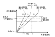
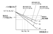
- FIG. 7 is an explanatory diagram for describing first voltage / current characteristics to be applied to each bidirectional DC / DC converter 14 at the time of charging operation. It is an explanatory view for explaining the 2nd voltage current characteristic given to each bidirectional DC / DC converter 14 at the time of electric discharge operation.
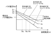
- FIG. 7 is an explanatory view for explaining another first voltage / current characteristic to be applied to each bidirectional DC / DC converter 14;
- FIG. 8 is an explanatory view for explaining another second voltage / current characteristic to be applied to each bidirectional DC / DC converter 14;
- direct current feed system is not limited to the following embodiments.
- components described below include those which can be easily conceived by those skilled in the art, and substantially the same components, and the components can be appropriately combined.
- the DC power supply system 1 includes a DC bus 2 and one or more power generation devices 3 (in the present example, two power generation devices 3a and 3b, hereinafter referred to as “power generation device 3” if not distinguished).
- power generation device 3 two power generation devices 3a and 3b, hereinafter referred to as “power generation device 3” if not distinguished.
- first converter 4 two power conditioners 4a and 4b described later as an example in the present example
- load devices 71 connected to the DC power supply system 1 two load devices as an example in the present example
- 71a, 71b hereinafter also referred to as "load device 71" when not distinguished
- the second converters 5 in this example, two second converters 5a, 5b described later as an example
- second converter 5" a plurality of direct-current power supply 6 (DC power supply device 6 1, 6 2, ⁇ ⁇ ⁇ , 6 n), the third converter 7, and the power management apparatus , And generates a DC voltage based on the power generated by the power generation device 3 and is not connected to a stand-alone DC power supply system (commercial AC power supply) that can supply one or more load devices 71 It is configured as a DC power supply system).
- DC power supply device 6 1, 6 2, ⁇ ⁇ ⁇ , 6 n the third converter 7, and the power management apparatus
- the DC bus 2 is laid over the installation place of the power generation device 3, the installation place of each DC power supply 6, and the installation place of the load device 71, and functions as a bus bar of DC power supply.
- DC bus 2 is within a predetermined voltage range including a nominal bus voltage (for example, DC 370 V as a nominal bus voltage) by charge / discharge operation of a bi-directional DC / DC converter 14 described later in the plurality of DC power supply devices 6.
- the bus voltage Vbs is defined in a voltage range of DC 340 V or more and DC 400 V or less).
- the first converter 4 is composed of two power conditioners 4a and 4b arranged corresponding to the two power generation devices 3a and 3b in this example.
- power conditioner 4a is configured to include an AC / DC converter, and is disposed corresponding to power generation device 3a.
- the power conditioner 4a operates with the DC voltage internally generated based on the AC voltage V1, and is controlled by the power management device 9 to generate the AC voltage V1 as the generated power output from the power generation device 3a as a bus.
- Converted to voltage Vbs for example, a voltage below the upper limit voltage value of the predetermined voltage range and above the nominal bus voltage in the first converter 4; a voltage value near the upper limit voltage value
- the power conditioner 4a measures the generated power W1 supplied from the power generation device 3a to the DC bus 2 (measured at a predetermined cycle T (for example, every few seconds)) and outputs it to the power management unit 9 It has a measurement function.
- Power conditioner 4b includes a DC / DC converter as an example, and is disposed corresponding to power generation device 3b.
- the power conditioner 4b operates with the DC voltage internally generated based on the DC voltage V2, and is controlled by the power management device 9 to control the power generation operation of the corresponding power generation device 3b to generate generated power. While being configured to be controllable, the DC voltage V2 as the generated power output from the power generation device 3b is converted to the bus voltage Vbs and supplied to the DC bus 2. Further, the power conditioner 4b has a power measurement function of measuring the generated power W2 supplied from the power generation device 3b to the DC bus 2 (for example, by measuring in a cycle T) and outputting it to the power management device 9. There is.
- the DC / DC converter 5a also has a current limiting function of limiting the load current supplied from the DC bus 2 to the load device 71a with the upper limit current value set from the power management unit 9. Further, the DC / DC converter 5a measures the load power WLa supplied from the DC bus 2 to the load device 71a based on the load voltage VLa and the load current (for example, by measuring in a cycle T). It has the power measurement function to output to 9.
- the DC / DC converter 5b is controlled by the power management device 9 to convert the bus voltage Vbs into a load voltage VLb which is a DC voltage used by the load device 71b (DC voltage conversion), and supplies the load voltage 71b to the load device 71b. . Further, the DC / DC converter 5 b has a current limiting function of limiting the load current supplied from the DC bus 2 to the load device 71 b with the upper limit current value set from the power management device 9. Further, the DC / DC converter 5b measures the load power WLb supplied from the DC bus 2 to the load device 71b based on the load voltage VLb and the load current (for example, by measuring in a cycle T). It has the power measurement function to output to 9.
- the load devices 71a and 71b are DC loads that operate by receiving the load voltages VLa and VLb (hereinafter, referred to as load voltage VL unless otherwise specified), which are DC voltages, and are, for example, DC voltages. It consists of lighting devices that operate, household appliances such as televisions and refrigerators that operate with DC voltage, and information devices such as personal computers and mobile terminals that operate with DC voltage.
- DC power supply device 6 includes a DC power supply device 6 1, 6 2, ⁇ ⁇ ⁇ , n-number of 6 n (n is an integer of 2 or more. Or less, particularly when no distinction is also referred to as a DC power supply device 6) is disposed There is.
- Each DC power supply device 6 is configured to include a storage battery 11, a battery management unit (BMU (Battery Management Unit)) 12, a contactor 13 and a bidirectional DC / DC converter 14, respectively.
- BMU Battery Management Unit
- the storage batteries 11 1 , 11 2 ,..., 11 n are used for supplying power to the DC bus 2 and are generally A large capacity and inexpensive storage battery such as a lead storage battery or a nickel hydrogen storage battery, which is constituted by a storage battery of the same type (for example, a lead storage battery having the same nominal voltage) and the same capacity (the same nominal capacity) There is. In addition, it can also be comprised with expensive storage batteries, such as a lithium ion battery and a NAS battery (sodium-sulfur battery). Storage battery 11 is configured to be capable of charge operation and discharge operation within a predetermined working voltage range including a nominal voltage.
- the BMU 12 executes the control contents indicated by the contactor control information to the contactor 13 (when the control content is a cutoff instruction, the contactor 13 shifts to the cutoff state).
- the control content is a connection instruction
- the contactor 13 is also brought into a connected state.
- Contactor 13 1, 13 2, ..., 13 n (hereinafter, when not particularly distinguished, also referred to as contactor 13), the corresponding storage battery 11 1, 11 2, ..., and positive and negative 11 n, corresponding .., 14 n are disposed between the storage batteries 11 1 , 11 2 ,..., 11 n on the side of the storage batteries 11 1 , 14 2 ,. Operate with the operating voltage Vop.
- Each contactor 13 is controlled by the corresponding BMU 12 to shift to any one of the blocking state and the coupling state, and in the blocking state, the positive electrode and the negative electrode, and the pair of input / output terminals Are cut off (disconnected), and in the connected state, the positive electrode and the negative electrode are connected to the pair of input / output terminals.
- the bidirectional DC / DC converter 14 performs CC operation (charging / discharging operation in a constant current system) with a DC voltage generated internally based on the bus voltage Vbs, and is operation controlled by the power management device 9.
- the bi-directional DC / DC converter 14 when the control information received from the power management apparatus 9 is a charge instruction, the bi-directional DC / DC converter 14 includes a first voltage / current characteristic (a second voltage / current characteristic added from the power management apparatus 9) included in the control information.
- the current value of the charging current is determined from (voltage current characteristics) and the voltage between the other pair of input / output terminals (that is, bus voltage Vbs), and the bus voltage Vbs input from the other pair of input / output terminals is boosted.
- step-down voltage conversion
- the charging current is supplied to the storage battery 11 with the determined current value (determined current value) to charge the storage battery 11 ( Execute charging operation with constant current).
- the first voltage-current characteristic corresponds to the first DC current (in this case, charging current) as the DC voltage (that is, the bus voltage Vbs) supplied to the DC bus 2 increases. It is a voltage-current characteristic that increases functionally.
- bidirectional DC / DC converter 14 includes the second voltage-current characteristic (the second voltage-current characteristic provided from power management device 9) included in the control information and the other.
- the current value of the discharge current is determined from the voltage between the pair of input / output terminals (that is, the bus voltage Vbs), and the charge voltage Vba of the storage battery 11 input from one pair of input / output terminals is boosted or reduced (voltage conversion)
- the discharge current is output from the storage battery 11 at the determined current value (determination current value) by outputting to the DC bus 2 from the other pair of input / output terminals (discharges the storage battery 11 (discharge with constant current) Perform the action)). Further, as shown in FIG.
- the bidirectional DC / DC converter 14 shifts to a sleep state in which its operation is stopped to reduce power consumption.
- the bi-directional DC / DC converter 14 receives a charge instruction or a discharge instruction as control information in the sleep state, the bi-directional DC / DC converter 14 leaves the sleep state and executes the charge operation or the discharge operation.
- the bidirectional DC / DC converter 14 also has a current limiting function of limiting each current value of the charging current supplied to the storage battery 11 and the discharge current discharged from the storage battery 11 to the maximum current value or less of the storage battery 11.
- the third converter 7 is configured of a DC / DC converter (hereinafter, also referred to as a DC / DC converter 7). Further, DC / DC converter 7 operates using bus voltage Vbs supplied from DC bus 2 as an operating voltage as an example in the present example, but instead of this configuration, a dedicated power supply (not shown) is provided It can also be configured to operate at an operating voltage supplied from a power supply. In addition, DC / DC converter 7 is used in BMU 12 and contactor 13 of each DC power supply device 6 and power management device 9 by stepping up or down (voltage conversion) this bus voltage Vbs in the operating state. The operation voltage Vop is generated and output.
- DC / DC converter 7 operates using bus voltage Vbs supplied from DC bus 2 as an operating voltage as an example in the present example, but instead of this configuration, a dedicated power supply (not shown) is provided It can also be configured to operate at an operating voltage supplied from a power supply.
- DC / DC converter 7 is used in BMU 12 and contactor 13 of each DC power supply device
- the power management device 9 is configured by a computer operating at the operation voltage Vop and functions as a control unit.
- the power management device 9 performs charge / discharge control processing for each DC power supply device 6, and power generation control for the power generation device 3 (other power generation devices 3 other than the power generation device 3a manually operated and controlled. In this example, the power generation device 3b). Processing and power control processing for the second converter 5 are executed.
- the power management device 9 also executes a voltage measurement process of measuring the bus voltage Vbs. In this case, the power management apparatus 9 can adopt a configuration in which the bus voltage Vbs is directly measured.
- the first converter 4 (at least one of the power conditioners 4a and 4b)
- a configuration in which the power management apparatus 9 indirectly measures the bus voltage Vbs via the first converter 4 may be employed so that the bus voltage Vbs is measured and output to the power management apparatus 9.
- each storage battery 11 has its charging voltage Vba in the working voltage range and its SOC not in alignment. Also, each contactor 13 is initially in the disconnected state.
- the power generation device 3a when the power generation device 3a is in operation, the power generation device 3a outputs the AC voltage V1.
- the power conditioner 4a operates by receiving the supply of the AC voltage V1, converts the AC voltage V1 into the bus voltage Vbs, and supplies the bus voltage Vbs to the DC bus 2. Further, the power conditioner 4 a measures the generated power W 1 supplied from the power generation device 3 a to the DC bus 2 at a cycle T, and outputs it to the power management device 9.
- the power conditioner 4b operates by receiving the supply of the DC voltage V2, converts the DC voltage V2 into the bus voltage Vbs, and supplies the bus voltage Vbs to the DC bus 2. Further, the power conditioner 4 b measures the generated power W 2 supplied from the power generation device 3 b to the DC bus 2 at a cycle T, and outputs it to the power management device 9.
- the power management apparatus 9 sends the bidirectional DC / DC converter 14 as described later.
- the discharging operation is performed to discharge the storage battery 11, thereby maintaining the bus voltage Vbs of the DC bus 2 within a predetermined voltage range including the nominal bus voltage.
- the DC / DC converter 7 receiving the supply of the bus voltage Vbs maintained in the predetermined voltage range in this manner operates in the normal state.
- the operation voltage Vop is output (supplied) to the BMU 12, the contactor 13, and the power management device 9. Therefore, in the normal state, the BMU 12 and the contactor 13 of each DC power supply device 6 and the power management device 9 are in the operating state.
- BMUs 12 1 to 12 n of each of DC power supply devices 6 1 to 6 n measure the charging voltage Vba or the like for corresponding storage batteries 11 1 to 11 n at period T, and each time they are measured, as battery information It is output to the power management unit 9.
- the power management apparatus 9 executes the voltage measurement process at a cycle T to measure the bus voltage Vbs, and performs the charge / discharge control process.
- the power management device 9 determines that the power can be supplied to the load device 71, and transmits power to the DC / DC converters 5a and 5b. Then, control is performed to convert and output the bus voltage Vbs so as to obtain the load voltages VLa and VLb used by the corresponding load devices 71a and 71b.
- Each DC / DC converter 5a, 5b measures the load power WLa, WLb supplied to the corresponding load device 71a, 71b when the load voltage VLa, VLb is output to the corresponding load device 71a, 71b. It outputs to the power management unit 9 at a cycle T.
- the power management apparatus 9 calculates the total load power (WLa + WLb) each time it obtains new load powers WLa and WLb.
- the power management apparatus 9 compares the calculated total generated power (W1 + W2) with the total load power (WLa + WLb), and when the total generated power (W1 + W2) exceeds the total load power (WLa + WLb), It is determined that the storage battery 11 is to be charged, and when the total generated power (W1 + W2) is less than the total load power (WLa + WLb), it is determined that the storage battery 11 of each DC power supply 6 is to be discharged.
- the power management device 9 acquires it from the BMU 12 of each DC power supply 6 as a result of the total generated power (W1 + W2) exceeding the total load power (WLa + WLb).
- DC power supply having a storage battery 11 that can be charged based on the stored battery information (the storage battery 11 in which the charging voltage Vba has not reached the upper limit of the working voltage range, in other words, the SOC (remaining battery) has not reached 100%)
- contact control information indicating a connection instruction is output to the BMU 12 of the specified DC power supply device 6, and a first voltage and current to the bidirectional DC / DC converter 14 of the DC power supply device 6.
- Output control information including characteristics (see FIG. 2) and charge instruction. That is, the power management device 9 executes the charging operation of charging the storage battery 11 of the DC power supply device 6 with the difference power (surplus power) between the total generated power (W1 + W2) and the total load power (WLa + WLb). Further, the power management apparatus 9 divides the differential power in this cycle T by the bus voltage Vbs measured in this cycle T, so that the total amount of surplus current that can be used to charge the storage battery 11 in this cycle T (that is, charging Calculate the total amount of current).
- the specified bi-directional DC / DC converter 14 is, for example, three bi-directional DC / DC converters 14 1 to 14 3 , and each bi-directional DC / DC converter 14 1 to 14 3 SOC 1 to SOC 3 are, for example, SOC 1 > SOC 2 > SOC 3 (all of which have less than 100% battery remaining) at the start of cycle T.
- the power management apparatus 9 first performs bidirectional DC in this determination process.
- Vbs a 3 ⁇ Ic + b 3 linear functions
- each of b 1 , b 2 and b 3 as an intercept of a linear function equation showing each first voltage-current characteristic is the same, and in the present example, each b 1 , b 2 and b 3 is for ease of understanding.
- power management device 9 performs corresponding bidirectional DC /
- a 1 , a 2 and a 3 is determined as the slope of a linear function equation showing the first voltage-current characteristics of the DC converters 14 1 , 14 2 and 14 3 .
- the power management unit 9, the storage battery 11 1, 11 2, 11 each battery 11 1 by charging the 3, 11 2, (so as to the aligned so) 11 3 to close the SOC 1 ⁇ SOC 3
- the SOC is different from the other storage battery 11 so that the charging current Ic to the storage battery 11 whose SOC is larger than the SOC of the other storage batteries 11 is smaller than the charging current Ic to the other storage battery 11.
- the charging current Ic to the storage battery 11 smaller than the SOC of 11 determines each of a 1 , a 2 , and a 3 so as to be larger than the charging current Ic to the other storage battery 11.
- each charging current such that each charging current Ic 1 , Ic 2 , Ic 3 to storage batteries 11 1 , 11 2 , 11 3 at voltage Vbs (common) has a relationship with Ic 3 > Ic 2 > Ic 1
- Each of a 1 , a 2 , and a 3 is determined such that the total sum of Ic 1 , Ic 2 , and Ic 3 matches the total amount of charging current available for charging the storage battery 11.
- each a 1 to a 3 has a value corresponding to each SOC 1 to SOC 3 That is, as the SOC of the corresponding storage battery 11 is larger, the gradient a of the first voltage-current characteristic to be applied to each bidirectional DC / DC converter 14 is larger (in this example, SOC 1 > SOC 2 > because it is SOC 3, such that a 1> a 2> a 3 ), to determine the slope a.
- the storage battery 11 of the big SOC 1 is charged with a small charging current Ic 1
- storage battery 11 2 small SOC 2 than SOC 1 a large charging current than charging current Ic 1 Ic 2 in is charged
- the storage battery 11 3 small SOC 3 than SOC 2 is charged with a large charging current Ic 3 than the charging current Ic 2. That is, each of the storage batteries 11 1 , 11 2 and 11 3 is charged such that the SOC 1 to SOC 3 are close to each other.
- each bi-directional DC / DC converter 14 1 , 14 2 , 14 3 performs the charging operation based on the applied first voltage-current characteristic, thereby suppressing the fluctuation of the bus voltage Vbs (the bus voltage Vbs Stabilize) to maintain the bus voltage Vbs within a predetermined voltage range.
- the BMU 12 of each DC power supply device 6 While identifying the DC power supply 6 having the rechargeable storage battery 11 (the storage battery 11 in which the charging voltage Vba has not reached the lower limit value of the working voltage range) based on the battery information obtained from BMU 12 of the identified DC power supply 6 Outputs contact control information indicating a connection instruction, and outputs control information including a second voltage / current characteristic (see FIG. 3) and a discharge instruction to bidirectional DC / DC converter 14 of DC power supply device 6 Do.
- the power management device 9 discharges the storage battery 11 of the DC power supply 6 by discharging the difference power (under power) between the total generated power (W1 + W2) and the total load power (WLa + WLb). Further, the power management apparatus 9 divides the difference power in this cycle T by the bus voltage Vbs measured in this cycle T, to thereby calculate the total amount of undercurrent that runs short in this cycle T (that is, the discharge current discharged from the storage battery 11). Calculate the total amount of
- the specified bi-directional DC / DC converter 14 is, for example, three bi-directional DC / DC converters 14 1 to 14 3 , and each bi-directional DC / DC converter 14 1 to 14 3 SOC 1 to SOC 3 are, for example, SOC 1 > SOC 2 > SOC 3 (all of which have less than 100% battery remaining) at the start of cycle T.
- the power management apparatus 9 first performs bidirectional DC in this determination process.
- Vbs a 2 ⁇ Id + b 2
- each of b 1 , b 2 , and b 3 as an intercept of a linear function equation indicating each second voltage-current characteristic is the same, and a predefined voltage equal to or higher than the upper limit value of the predetermined voltage range including the nominal bus voltage br (re
- Vbs a 1 ⁇ Id + br
- Vbs a 2 ⁇ Id + br
- Vbs a 3 ⁇ Id + br
- the power management apparatus 9 and the total amount of discharge current to be discharged from the storage battery 11 calculated, the storage battery 11 1, 11 2, based on each of SOC 1 ⁇ SOC 3 of 11 3, corresponding bidirectional DC / DC converter 14
- Each of a 1 , a 2 and a 3 (a negative coefficient in the discharge operation) is determined as the slope of a linear function equation showing the second voltage-current characteristics of 1 , 14 2 and 14 3 .
- each a 1 to a 3 has a value corresponding to each SOC 1 to SOC 3 That is, as the SOC of the corresponding storage battery 11 is larger, the absolute value of the slope a of the second voltage-current characteristic to be applied to each bidirectional DC / DC converter 14 is smaller (in this example, SOC 1 Since> SOC 2 > SOC 3 and each gradient a is negative, the gradient a is determined so that the absolute value of the gradient a is
- the storage battery 11 of the big SOC 1 is discharged with a large discharge current Id 1
- the storage battery 11 2 small SOC 2 than SOC 1 is smaller discharge than the discharge current Id 1 current Id 2 in is discharged
- battery 11 3 small SOC 3 than SOC 2 is discharged with a small discharging current Id 3 than the discharge current Id 2. That is, each of the storage batteries 11 1 , 11 2 and 11 3 is discharged such that the SOC 1 to SOC 3 approach each other.
- each bi-directional DC / DC converter 14 1 , 14 2 , 14 3 suppresses the fluctuation of the bus voltage Vbs by performing the discharging operation based on the applied second voltage-current characteristic (a bus voltage Stabilize Vbs) and maintain the bus voltage Vbs within a predetermined voltage range.
- the power management device 9 transmits each bidirectional DC / DC converter 14 at period T based on the difference power between the total generated power (W1 + W2) and the total load power (WLa + WLb).
- the first voltage-current characteristic (see FIG. 2) in which the charging current Ic is linearly increased with the increase of the bus voltage Vbs when determining whether the charging operation or the discharging operation is to be performed with respect to the charging operation.
- gradient corresponding to the SOC of the corresponding battery 11 battery remaining amount
- the second voltage-current characteristic for decreasing the charging current Id linearly with the increase of Vbs (see FIG. 3) has a slope (for example, It applies to each bidirectional DC / DC converter 14 by a 1 to a 3 ) shown in FIG.
- FIG. 2 shows the intercepts b 1 , b 2 and b 3 of the linear functional equation indicating the first voltage-current characteristics to be applied when charging each bidirectional DC / DC converter 14.
- the intercepts b 1 , b 2 and b 3 of the linear functional equation indicating the first voltage-current characteristics to be applied when charging each bidirectional DC / DC converter 14.
- they are identical and defined as zero, for example, as shown in FIG. 4, at least one is a different value from the other, and at least one is a non-zero value (for example, as shown in FIG.
- Each slope a 1 to a 3 of the linear function equation representing the characteristic corresponds to the relationship of SOC 1 > SOC 2 > SOC 3 of the storage battery 11 to a relationship of a 1 > a 2 > a 3
- the bidirectional DC / DC converter 14 1 corresponding to the storage battery 11 1 of the largest SOC 1 is used to determine which bus voltage Vbs is any value within the predetermined voltage range including the nominal bus voltage.
- the charging current Ic 3 in countercurrent DC / DC converter 14 3 may be one the most increase.
- FIG. 3 shows intercepts b 1 , b 2 and b 3 of the linear functional equation showing the second voltage-current characteristics to be given when performing the discharge operation of each bidirectional DC / DC converter 14.
- the present invention is not limited thereto.
- at least one has different values from each other (in the figure, as an example, all different values). Configurations can also be adopted. Even if the sections b 1 , b 2 and b 3 have the configuration shown in FIG. 5, the second voltage and current applied to the bidirectional DC / DC converters 14 1 , 14 2 and 14 3 in the same manner as the configuration of FIG.
- Each slope a 1 to a 3 of the linear function equation showing the characteristic is made to correspond to the relationship between SOC 1 > SOC 2 > SOC 3 of SOC of each storage battery 11, and
- a 1 By determining the relationship with
Landscapes
- Engineering & Computer Science (AREA)
- Power Engineering (AREA)
- Charge And Discharge Circuits For Batteries Or The Like (AREA)
- Secondary Cells (AREA)
Abstract
複数の蓄電池の電池寿命のばらつきを低減する。 発電装置3a,3bの発電電力W1,W2を直流バス2に供給するパワーコンディショナ4a,4bと、バス電圧Vbsを電圧変換して負荷機器71a,71bに負荷電力WLa,WLbを供給するコンバータ5a,5bと、蓄電池111~11nを充電する充電動作および蓄電池11を放電させる放電動作を実行する双方向コンバータ141~14nと、発電電力が負荷電力を上回るときにはコンバータ14に充電動作を、下回るときにはコンバータ14に放電動作を実行させる電力管理装置9とを備え、電力管理装置9は、充電動作時には、バス電圧Vbsの増加に伴い充電電流を一次関数的に増加させる第1電圧電流特性を蓄電池11のSOCに応じた傾きで、また放電動作時には、バス電圧Vbsの増加に伴い放電電流を一次関数的に減少させる第2電圧電流特性をSOCに応じた傾きで各コンバータ14に付与する。
Description
本発明は、商用電源と接続されない独立型の直流給電システムに関するものである。
この種の直流給電システムとして、下記の特許文献1に開示された直流給電システムが知られている。この直流給電システムは、分散電源装置(例えば、太陽光発電装置、風力発電装置および燃料電池などの装置)と、分散電源装置を負荷に接続する直流バスと、複数の直流電源装置(蓄電池を含み、充放電可能な電源装置)と、直流バスに複数の直流電源装置をそれぞれ接続するコンバータ(例えば双方向DC/DCコンバータ)と、これらの複数のコンバータを制御する制御器とを備えている。また、この直流給電システムでは、エアコン、テレビおよび照明装置などの家電機器や、パソコンなどの情報機器が負荷として直流バスに接続されて、直流バスから直流電力(直流電圧)の供給を受けて動作する。また、この直流給電システムでは、制御器は、分散電源装置より直流バスに供給される電圧が所定値と異なるとき、少なくとも1つのコンバータによって1つの直流電源装置から直流バスへ電力供給し、他の少なくとも1つのコンバータによって、直流バスの電圧を所定値に保つように直流バスから他の直流電源装置へ直流電力を供給するように制御する。
この直流給電システムによれば、分散電源装置から直流バスに出力される直流電圧の変動が大きくても、直流バスの電圧(直流電圧)を安定させることができることから、直流バスに接続された負荷に対して安定な出力電圧(直流電圧)を供給することが可能となっている。
しかしながら、上記した従来の直流給電システムを含む公知の直流給電システムでは、複数の直流電源装置としての蓄電池と直流バスとの間に接続されるコンバータ(双方向DC/DCコンバータ)はすべてCV型(定電圧(constant voltage)充電型)であることから、各蓄電池として同じ仕様のものを使用し、かつ各コンバータとして同じ仕様のものを使用したとしても、各蓄電池および各コンバータには製造誤差が存在し、また蓄電池とコンバータとを接続する配線や、コンバータと直流バスとを接続する配線についても全く同じ長さにすることは困難なため(つまり、配線抵抗にばらつきが生じるため)、各蓄電池の充放電電流の電流値は同じ値とはならない。このため、各蓄電池に対する充放電が繰り返された際には、蓄電池毎に電池残量に差が生じ、これに起因して蓄電池毎に充放電サイクル数にも差が生じるようになることから、各蓄電池の電池寿命にばらつきが生じるという改善すべき課題が存在している。
本発明は、上記課題に鑑みてなされたものであり、直流バスに接続される複数の蓄電池についての電池寿命のばらつきを大幅に低減し得る直流給電システムを提供することを目的とする。
上記目的を達成すべく、本発明に係る直流給電システムでは、直流給電の母線となる直流バスと、発電装置と、前記発電装置の発電電力を前記直流バスに供給する第1コンバータと、前記直流バスに供給されている直流電圧を電圧変換して負荷機器に供給する第2コンバータと、複数の蓄電池と、前記複数の蓄電池の各々と前記直流バスとの間に接続されて、当該直流バスに供給されている直流電圧と当該蓄電池の直流電圧とを双方向に電圧変換して、当該直流バスから当該蓄電池へ、または当該蓄電池から当該直流バスへ直流電流を供給する複数の双方向コンバータと、前記発電装置での前記発電電力と前記第2コンバータから前記負荷機器に供給されている負荷電力とを比較して、当該発電電力が当該負荷電力を上回るときには、前記各双方向コンバータに対して前記直流電流を前記蓄電池へ供給させる充電動作を実行させ、当該発電電力が当該負荷電力を下回るときには、前記各双方向コンバータに対して前記直流電流を前記直流バスへ供給させる放電動作を実行させる制御部とを備えている独立型の直流給電システムであって、前記制御部は、前記充電動作を実行させる際には、前記直流バスに供給されている前記直流電圧の増加に伴い前記直流電流を一次関数的に増加させる第1電圧電流特性を、対応する前記蓄電池の電池残量に応じた傾きで前記各双方向コンバータに対して付与し、前記放電動作を実行させる際には、前記直流バスに供給されている前記直流電圧の増加に伴い前記直流電流を一次関数的に減少させる第2電圧電流特性を、対応する前記蓄電池の電池残量に応じた傾きで前記各双方向コンバータに対して付与する。
具体的には、前記制御部は、前記各双方向コンバータに対して、前記対応する蓄電池の前記電池残量が大きいほど前記傾きが大きくなる前記第1電圧電流特性を付与すると共に、前記対応する蓄電池の前記電池残量が大きいほど前記傾きの絶対値が小さくなる前記第2電圧電流特性を付与する。
具体的には、前記制御部は、前記各双方向コンバータに対して、前記対応する蓄電池の前記電池残量が大きいほど前記傾きが大きくなる前記第1電圧電流特性を付与すると共に、前記対応する蓄電池の前記電池残量が大きいほど前記傾きの絶対値が小さくなる前記第2電圧電流特性を付与する。
本発明によれば、充電動作においては、他の蓄電池よりも大きな電池残量の蓄電池は小さな充電電流で充電される(言い換えれば、他の蓄電池よりも小さな電池残量の蓄電池は大きな充電電流で充電される)ため、各蓄電池をそれぞれの電池残量が近づくように(揃うように)充電することができ、一方、放電動作においては、他の蓄電池よりも大きな電池残量の蓄電池は大きな放電電流で放電される(言い換えれば、他の蓄電池よりも小さな電池残量の蓄電池は小さな放電電流で放電される)ため、各蓄電池をそれぞれの電池残量が近づくように(揃うように)放電させることができる。これにより、この直流給電システムによれば、各蓄電池に対する充放電が繰り返された際にも、各蓄電池の電池残量を近い状態(ほぼ揃った状態)に維持することができることから、蓄電池毎に充放電サイクル数に差が生じるという事態を回避することができる結果、各蓄電池の電池寿命にばらつきが生じるという事態の発生を大幅に低減することができる。
本発明によれば、直流バスに接続される複数の蓄電池についての電池寿命のばらつきを大幅に低減することができる。
以下、直流給電システムの実施の形態について、添付図面を参照して説明する。なお、直流給電システムは以下の実施形態に限定されるものではない。また、以下に記載した構成要素には、当業者が容易に想定できるもの、実質的に同一のものが含まれると共に、その構成要素は、適宜組み合わせることが可能である。
最初に、直流給電システムとしての直流給電システム1の構成について説明する。
直流給電システム1は、直流バス2、1または2以上の発電装置3(本例では一例として2つの発電装置3a,3b。以下、区別しないときには「発電装置3」ともいう)、発電装置3に対応して配設された第1コンバータ4(本例では一例として後述する2つのパワーコンディショナ4a,4b)、直流給電システム1に接続される負荷機器71(本例では一例として2つの負荷機器71a,71b。以下、区別しないときには「負荷機器71」ともいう)に対応して配設された第2コンバータ5(本例では一例として後述する2つの第2コンバータ5a,5b。以下、区別しないときには「第2コンバータ5」ともいう)、複数の直流電源装置6(直流電源装置61,62,・・・,6n)、第3コンバータ7、および電力管理装置9を備え、発電装置3で発電された電力に基づいて直流電圧を生成して、1または2以上の負荷機器71に供給可能な独立型の直流給電システム(商用電源(商用交流電源)に接続されない直流給電システム)として構成されている。
直流バス2は、発電装置3の設置場所、各直流電源装置6の設置場所および負荷機器71の設置場所に亘って敷設されて、直流給電の母線として機能する。また、直流バス2は、複数の直流電源装置6内の後述する双方向DC/DCコンバータ14の充放電動作により、公称バス電圧を含む所定の電圧範囲内(例えば、公称バス電圧としてのDC370Vを含むDC340V以上DC400V以下の電圧範囲内)にバス電圧Vbsが規定される。
発電装置3は、分散型電源装置で構成されている。この場合、分散型電源装置は、太陽光発電装置および風力発電装置などの自然再生エネルギーを利用した発電装置や、軽油およびガソリンなどの化石エネルギーを利用したエンジン方式の発電装置で構成することが可能である。本例では一例として、発電装置3aは、エンジン方式の発電装置であって、動作状態において、所定の電圧値の交流電圧V1を生成して出力する。また、発電装置3bは、一例として1または2以上の太陽光発電装置で構成されて、昼間には自動的に発電して、直流電圧V2を生成して出力する。
第1コンバータ4は、本例では2つの発電装置3a,3bに対応して配設された2つのパワーコンディショナ4a,4bで構成されている。本例では一例として、パワーコンディショナ4aは、AC/DCコンバータを含んで構成されて、発電装置3aに対応して配設されている。また、パワーコンディショナ4aは、交流電圧V1に基づいて内部で生成した直流電圧で動作すると共に、電力管理装置9によって制御されて、発電装置3aから出力される発電電力としての交流電圧V1をバス電圧Vbs(例えば、第1コンバータ4では、所定の電圧範囲の上限電圧値を下回り、かつ公称バス電圧を上回る電圧。この上限電圧値近傍の電圧値)に変換して、直流バス2に供給する。また、パワーコンディショナ4aは、発電装置3aから直流バス2に供給している発電電力W1を計測して(所定の周期T(例えば数秒間隔)で計測して)電力管理装置9に出力する電力計測機能を有している。
パワーコンディショナ4bは、一例としてDC/DCコンバータを含んで構成されて、発電装置3bに対応して配設されている。また、パワーコンディショナ4bは、直流電圧V2に基づいて内部で生成した直流電圧で動作すると共に、電力管理装置9によって制御されて、対応する発電装置3bの発電動作を制御することで発電電力を制御可能に構成されると共に、発電装置3bから出力される発電電力としての直流電圧V2をバス電圧Vbsに変換して、直流バス2に供給する。また、パワーコンディショナ4bは、発電装置3bから直流バス2に供給されている発電電力W2を計測して(例えば周期Tで計測して)電力管理装置9に出力する電力計測機能を有している。
第2コンバータ5は、例えば、バス電圧Vbsに基づいて内部で生成した直流電圧で動作するDC/DCコンバータで構成されている。本例では、理解の容易のため、一例として、直流給電システム1に接続される負荷機器71(直流負荷)は負荷機器71a,71bの2つであるとして、第2コンバータ5は、負荷機器71aに対応する第2コンバータ5a(DC/DCコンバータ5aともいう)と、負荷機器71bに対応する第2コンバータ5b(DC/DCコンバータ5bともいう)の2つで構成されているものとする。この場合、DC/DCコンバータ5aは、電力管理装置9によって制御されて、バス電圧Vbsを負荷機器71aで使用される直流電圧である負荷電圧VLaに変換(直流電圧変換)して、負荷機器71aに供給する。また、DC/DCコンバータ5aは、直流バス2から負荷機器71aに供給される負荷電流について、電力管理装置9から設定された上限電流値で制限する電流制限機能を有している。また、DC/DCコンバータ5aは、この負荷電圧VLaおよび負荷電流に基づき、直流バス2から負荷機器71aに供給されている負荷電力WLaを計測して(例えば周期Tで計測して)電力管理装置9に出力する電力計測機能を有している。
DC/DCコンバータ5bは、電力管理装置9によって制御されて、バス電圧Vbsを負荷機器71bで使用される直流電圧である負荷電圧VLbに変換(直流電圧変換)して、負荷機器71bに供給する。また、DC/DCコンバータ5bは、直流バス2から負荷機器71bに供給される負荷電流について、電力管理装置9から設定された上限電流値で制限する電流制限機能を有している。また、DC/DCコンバータ5bは、この負荷電圧VLbおよび負荷電流に基づき、直流バス2から負荷機器71bに供給されている負荷電力WLbを計測して(例えば周期Tで計測して)電力管理装置9に出力する電力計測機能を有している。
なお、負荷機器71a,71bは、直流電圧である負荷電圧VLa,VLb(以下、特に区別しないときには、負荷電圧VLともいう)の供給を受けて動作する直流負荷であって、例えば、直流電圧で動作する照明機器、直流電圧で動作するテレビおよび冷蔵庫などの家電製品、並びに直流電圧で動作するパソコンや携帯端末などの情報機器などで構成される。
直流電源装置6は、直流電源装置61,62,・・・,6nのn個(nは2以上の整数。以下、特に区別しないときには、直流電源装置6ともいう)配設されている。各直流電源装置6は、蓄電池11、電池管理装置(BMU(Battery Management Unit ))12、コンタクタ13および双方向DC/DCコンバータ14をそれぞれ備えて構成されている。
蓄電池111,112,・・・,11n(以下、特に区別しないときには、蓄電池11ともいう)は、直流バス2への電力の供給のために使用されるものであり、一般的に、大容量であって、かつ安価な鉛蓄電池やニッケル水素電池などの蓄電池であって、同種(例えば、公称電圧が同じ鉛蓄電池)で、かつ同容量(公称容量が同じ)の蓄電池で構成されている。なお、リチウムイオン電池やNAS電池(ナトリウム硫黄電池)などの高価な蓄電池で構成することもできる。蓄電池11は、公称電圧を含む所定の使用電圧範囲内で、充電動作および放電動作が可能に構成されている。
BMU121,122,・・・,12n(以下、特に区別しないときには、BMU12ともいう)は、対応する各蓄電池111,112,・・・,11nにそれぞれ配設されて、後述する動作用電圧Vopで動作する。また、各BMU12は、動作状態において、一例として蓄電池11の充電電圧Vbaを計測する機能と、蓄電池11の充放電電流の電流値を計測してSOC(State of charge:電池残量(残容量) )を演算する機能と、計測した充電電圧Vbaや充放電電流の電流値や算出したSOCを含む情報を電池情報として所定の周期Tで電力管理装置9に出力する機能とを有している。また、BMU12は、電力管理装置9からコンタクタ制御情報を入力したときには、このコンタクタ制御情報で示される制御内容をコンタクタ13に対して実行する(制御内容が遮断指示のときにはコンタクタ13を遮断状態に移行させ、制御内容が連結指示のときにはコンタクタ13を連結状態に移行させる)機能も有している。
コンタクタ131,132,・・・,13n(以下、特に区別しないときには、コンタクタ13ともいう)は、対応する蓄電池111,112,・・・,11nの正極および負極と、対応する双方向DC/DCコンバータ141,142,・・・,14nにおける蓄電池111,112,・・・,11n側の一対の入出力端子との間に配設されて、後述する動作用電圧Vopで動作する。また、各コンタクタ13は、対応するBMU12によって制御されて、遮断状態および連結状態のうちの任意の一方の状態に移行し、遮断状態のときには、この正極および負極と、この一対の入出力端子とを遮断し(切り離し)、連結状態のときには、この正極および負極と、この一対の入出力端子とを連結する。
双方向コンバータとしての双方向DC/DCコンバータ141,142,・・・,14n(以下、特に区別しないときには、双方向DC/DCコンバータ14ともいう)は、上記したように蓄電池11側の一対の入出力端子(一方の一対の入出力端子)がコンタクタ13を介して蓄電池11に接続されると共に、他方の一対の入出力端子が直流バス2に接続されることで、蓄電池11と直流バス2との間に接続(配設)されている。双方向DC/DCコンバータ14については、例えば特開2016-152641号公報に開示の公知の双方向DC/DCコンバータで構成することができる。
また、双方向DC/DCコンバータ14は、バス電圧Vbsに基づいて内部で生成した直流電圧でCC動作(定電流方式での充電・放電動作)すると共に、電力管理装置9によって動作制御される。
具体的には、双方向DC/DCコンバータ14は、電力管理装置9から受信した制御情報が充電指示のときには、この制御情報に含まれる第1電圧電流特性(電力管理装置9から付与された第1電圧電流特性)と他方の一対の入出力端子間の電圧(つまり、バス電圧Vbs)とから充電電流の電流値を決定し、他方の一対の入出力端子から入力したバス電圧Vbsを昇圧または降圧(電圧変換)して一方の一対の入出力端子から蓄電池11に出力することにより、この決定した電流値(決定電流値)で充電電流を蓄電池11に供給して、蓄電池11を充電する(定電流での充電動作を実行する)。また、この第1電圧電流特性とは、図2に示すように、直流バス2に供給されている直流電圧(つまり、バス電圧Vbs)の増加に伴い直流電流(この場合、充電電流)を一次関数的に増加させるという電圧電流特性である。
一方、双方向DC/DCコンバータ14は、受信した制御情報が放電指示のときには、この制御情報に含まれる第2電圧電流特性(電力管理装置9から付与された第2電圧電流特性)と他方の一対の入出力端子間の電圧(つまり、バス電圧Vbs)とから放電電流の電流値を決定し、一方の一対の入出力端子から入力した蓄電池11の充電電圧Vbaを昇圧または降圧(電圧変換)して他方の一対の入出力端子から直流バス2に出力することにより、この決定した電流値(決定電流値)で放電電流を蓄電池11から出力させる(蓄電池11を放電させる(定電流での放電動作を実行する))。また、この第2電圧電流特性とは、図3に示すように、直流バス2に供給されている直流電圧(つまり、バス電圧Vbs)の増加に伴い直流電流(この場合、放電電流)を一次関数的に減少させるという電圧電流特性である。
また、双方向DC/DCコンバータ14は、制御情報が停止指示のときには、自身の動作を停止させて消費電力を低減させるスリープ状態に移行する。また、双方向DC/DCコンバータ14は、スリープ状態において制御情報として充電指示または放電指示を受信したときには、スリープ状態から脱して、充電動作または放電動作を実行する。また、双方向DC/DCコンバータ14は、蓄電池11に供給する充電電流および蓄電池11から放電する放電電流の各電流値を蓄電池11の最大電流値以下に制限する電流制限機能を有している。
第3コンバータ7は、DC/DCコンバータで構成されている(以下、DC/DCコンバータ7ともいう)。また、DC/DCコンバータ7は、本例では一例として、直流バス2から供給されるバス電圧Vbsを作動電圧として動作するが、この構成に代えて、不図示の専用電源を設けて、この専用電源から供給される作動電圧で動作する構成とすることもできる。また、DC/DCコンバータ7は、動作状態において、このバス電圧Vbsを昇圧または降圧(電圧変換)することにより、各直流電源装置6のBMU12およびコンタクタ13と、電力管理装置9とで使用される動作用電圧Vopを生成して出力する。
電力管理装置9は、動作用電圧Vopで動作するコンピュータで構成されて、制御部として機能する。この電力管理装置9は、各直流電源装置6に対する充放電制御処理、発電装置3(手動で動作制御される発電装置3aを除く他の発電装置3。本例では、発電装置3b)に対する発電制御処理、および第2コンバータ5に対する電力制御処理を実行する。また、電力管理装置9は、バス電圧Vbsを計測する電圧計測処理を実行する。この場合、電力管理装置9は、バス電圧Vbsを直接的に計測する構成を採用することもできるし、例えば、第1コンバータ4(パワーコンディショナ4a,4bのうちの少なくとも一方)が発電電力と共にバス電圧Vbsを計測して電力管理装置9に出力する機能を有するようにして、電力管理装置9が第1コンバータ4を介してバス電圧Vbsを間接的に計測する構成を採用することもできる。
次に、図1に示した直流給電システム1の動作について説明する。なお、理解の容易のため、各蓄電池11については、それぞれの充電電圧Vbaが使用電圧範囲にあるものとし、それぞれのSOCは揃っていない状態にあるものとする。また、各コンタクタ13は、当初、遮断状態にあるものとする。
この直流給電システム1では、発電装置3aが動作状態のときには、発電装置3aが交流電圧V1を出力している。これにより、パワーコンディショナ4aが、交流電圧V1の供給を受けて動作して、この交流電圧V1をバス電圧Vbsに変換して直流バス2に供給する。また、パワーコンディショナ4aは、発電装置3aから直流バス2に供給されている発電電力W1を周期Tで計測して電力管理装置9に出力する。
また、発電装置3bが動作状態のときには、発電装置3bが直流電圧V2を出力している。これにより、パワーコンディショナ4bが、直流電圧V2の供給を受けて動作して、この直流電圧V2をバス電圧Vbsに変換して直流バス2に供給する。また、パワーコンディショナ4bは、発電装置3bから直流バス2に供給されている発電電力W2を周期Tで計測して電力管理装置9に出力する。
また、発電装置3aや発電装置3bが動作状態にないとき、または発電装置3bが動作状態であっても、発電電力W2が十分でないとき(後述するように、総発電電力(W1+W2)が予め規定された基準電力未満のとき)のように、総発電電力(W1+W2)が総負荷電力(WLa+WLb)を下回るときには、電力管理装置9は、後述するようにして双方向DC/DCコンバータ14に対して放電動作を実行させて、蓄電池11を放電させることで、直流バス2のバス電圧Vbsを公称バス電圧を含む所定の電圧範囲内に維持させる。
この直流給電システム1では、通常状態において、このようにして所定の電圧範囲内に維持されているバス電圧Vbsの供給を受けているDC/DCコンバータ7が動作して、各直流電源装置6のBMU12およびコンタクタ13と、電力管理装置9とに動作用電圧Vopを出力(供給)している。このため、通常状態において、各直流電源装置6のBMU12およびコンタクタ13と、電力管理装置9はそれぞれ動作状態にある。
したがって、各直流電源装置61~6nのBMU121~12nは、対応する蓄電池111~11nについての充電電圧Vba等を周期Tで計測すると共に、これらを計測する都度、電池情報として電力管理装置9に出力している。
また、電力管理装置9は、周期Tで電圧計測処理を実行してバス電圧Vbsを計測しつつ、充放電制御処理を実行している。
この充放電制御処理では、電力管理装置9は、発電装置3a側のパワーコンディショナ4aからの新たな発電電力W1および発電装置3b側のパワーコンディショナ4bからの新たな発電電力W2を取得する都度(周期Tで)、総発電電力(W1+W2)を算出する。
また、電力管理装置9は、この総発電電力(W1+W2)が予め規定された基準電力以上のときには、負荷機器71への電力供給が可能と判別して、各DC/DCコンバータ5a,5bに対して、対応する負荷機器71a,71bで使用される負荷電圧VLa,VLbとなるようにバス電圧Vbsを変換して出力させる制御を実行する。各DC/DCコンバータ5a,5bは、対応する負荷機器71a,71bに負荷電圧VLa,VLbを出力しているときには、対応する負荷機器71a,71bに供給されている負荷電力WLa,WLbを計測して電力管理装置9に周期Tで出力する。電力管理装置9は、新たな負荷電力WLa,WLbを取得する都度、総負荷電力(WLa+WLb)を算出する。
電力管理装置9は、算出した総発電電力(W1+W2)と総負荷電力(WLa+WLb)とを比較して、総発電電力(W1+W2)が総負荷電力(WLa+WLb)を上回るときには、各直流電源装置6の蓄電池11への充電を実行すると判別し、総発電電力(W1+W2)が総負荷電力(WLa+WLb)を下回るときには、各直流電源装置6の蓄電池11からの放電を実行すると判別する。
電力管理装置9は、総発電電力(W1+W2)が総負荷電力(WLa+WLb)を上回る結果、各直流電源装置6の蓄電池11への充電を実行すると判別したときには、各直流電源装置6のBMU12から取得した電池情報に基づいて充電可能な蓄電池11(充電電圧Vbaが使用電圧範囲の上限値に達していない、言い換えれば、SOC(電池残量)が100%に達していない蓄電池11)を有する直流電源装置6を特定すると共に、特定した直流電源装置6のBMU12に対して連結指示を示すコンタクト制御情報を出力し、かつこの直流電源装置6の双方向DC/DCコンバータ14に対して第1電圧電流特性(図2参照)および充電指示を含む制御情報を出力する。つまり、電力管理装置9は、総発電電力(W1+W2)と総負荷電力(WLa+WLb)との差分電力(余剰電力)で、直流電源装置6の蓄電池11を充電する充電動作を実行する。また、電力管理装置9は、この周期Tにおいて計測したバス電圧Vbsでこの周期Tにおける差分電力を除算することにより、この周期Tにおいて蓄電池11の充電に使用可能な余剰電流の総量(つまり、充電電流の総量)を算出する。
この双方向DC/DCコンバータ14への第1電圧電流特性(バス電圧Vbsの増加に伴い充電電流(以下では、充電電流Icともいう)を一次関数的に増加させる電圧電流特性)の決定処理について説明する。なお、理解の容易のため、特定した双方向DC/DCコンバータ14が一例として双方向DC/DCコンバータ141~143の3つであり、各双方向DC/DCコンバータ141~143のSOC1~SOC3は、周期Tの開始時点において一例として、SOC1>SOC2>SOC3(いずれも電池残量は100%未満)となっているものとする。
この第1電圧電流特性は、充電電流Icの増加に伴い、バス電圧Vbsを一次関数的に増加させる電圧電流特性でもあることから、電力管理装置9は、この決定処理では、まず、双方向DC/DCコンバータ141の第1電圧電流特性を、Vbs=a1×Ic+b1の一次関数式で表される電圧電流特性と規定し、双方向DC/DCコンバータ142の第1電圧電流特性を、Vbs=a2×Ic+b2の一次関数式で表される電圧電流特性と規定し、双方向DC/DCコンバータ143の第1電圧電流特性を、Vbs=a3×Ic+b3の一次関数式で表される電圧電流特性と規定する。また、各第1電圧電流特性を示す一次関数式の切片としての各b1,b2,b3は同一であり、本例では理解の容易のため、各b1,b2,b3はゼロであるものとする。したがって、各双方向DC/DCコンバータ141,142,143の第1電圧電流特性はそれぞれ、Vbs=a1×Ic,Vbs=a2×Ic,Vbs=a3×Icと表される。
次いで、電力管理装置9は、算出した蓄電池11の充電に使用可能な充電電流の総量と、蓄電池111,112,113のそれぞれのSOC1~SOC3に基づき、対応する双方向DC/DCコンバータ141,142,143の第1電圧電流特性を示す一次関数式の傾きとしての各a1,a2,a3(充電動作では、正の係数)を決定する。
具体的には、電力管理装置9は、各蓄電池111,112,113に対する充電によって各蓄電池111,112,113のSOC1~SOC3を近づけるべく(揃うようにすべく)、SOCが他の蓄電池11のSOCよりも大きな蓄電池11への充電電流Icは、この他の蓄電池11への充電電流Icよりも小さくなるように、逆の見方をすれば、SOCが他の蓄電池11のSOCよりも小さな蓄電池11への充電電流Icは、この他の蓄電池11への充電電流Icよりも大きくなるように、各a1,a2,a3を決定する。この具体例では、各蓄電池111,112,113のSOCがSOC1>SOC2>SOC3との関係にあることから、電力管理装置9は、図2に示すように、現在のバス電圧Vbs(共通)での蓄電池111,112,113への各充電電流Ic1,Ic2,Ic3がIc3>Ic2>Ic1との関係になるように、かつ各充電電流Ic1,Ic2,Ic3の総和が蓄電池11の充電に使用可能な充電電流の上記の総量と一致するように、各a1,a2,a3を決定する。さらに、各傾きa1~a3と各SOC1~SOC3との関係について詳しく説明すると、電力管理装置9は、各a1~a3が各SOC1~SOC3に応じた値となるように、つまり、対応する蓄電池11のSOCが大きいほど、各双方向DC/DCコンバータ14に対して付与する第1電圧電流特性の傾きaが大きくなるように(この例では、SOC1>SOC2>SOC3であるから、a1>a2>a3となるように)、この傾きaを決定する。
したがって、このようにして決定された一次関数式(Vbs=a1×Ic,Vbs=a2×Ic,Vbs=a3×Ic)で示される第1電圧電流特性がそれぞれ付与された各双方向DC/DCコンバータ141,142,143は、周期Tにおいて、付与された第1電圧電流特性と現在のバス電圧Vbsとで規定される大きさの充電電流Ic1,Ic2,Ic3(Ic3>Ic2>Ic1)で、対応する蓄電池111,112,113へ充電を実行する。この結果、この周期Tにおいて、大きなSOC1の蓄電池111は、小さな充電電流Ic1で充電され、SOC1よりも小さなSOC2の蓄電池112は、充電電流Ic1よりも大きな充電電流Ic2で充電され、SOC2よりも小さなSOC3の蓄電池113は、充電電流Ic2よりも大きな充電電流Ic3で充電される。つまり、各蓄電池111,112,113は、それぞれのSOC1~SOC3が近づくように(揃うように)充電される。
また、各双方向DC/DCコンバータ141,142,143は、このような一次関数式(Vbs=a1×Ic,Vbs=a2×Ic,Vbs=a3×Ic)で示される第1電圧電流特性がそれぞれ付与されることから、バス電圧Vbsが現在のバス電圧Vbsから上昇したときには、それぞれの充電電流Ic1,Ic2,Ic3を第1電圧電流特性に従って増加させることで、バス電圧Vbsの上昇の度合いを抑制し、一方、バス電圧Vbsが現在のバス電圧Vbsから低下したときには、それぞれの充電電流Ic1,Ic2,Ic3を第1電圧電流特性に従って減少させることで、バス電圧Vbsの低下の度合いを抑制する。つまり、各双方向DC/DCコンバータ141,142,143は、付与された第1電圧電流特性に基づいて充電動作することで、バス電圧Vbsの変動を抑制して(バス電圧Vbsを安定化させて)、バス電圧Vbsを所定の電圧範囲内に維持する。
一方、電力管理装置9は、総発電電力(W1+W2)が総負荷電力(WLa+WLb)を下回る結果、各直流電源装置6の蓄電池11からの放電を実行すると判別したときには、各直流電源装置6のBMU12から取得した電池情報に基づいて放電可能な蓄電池11(充電電圧Vbaが使用電圧範囲の下限値に達していない蓄電池11)を有する直流電源装置6を特定すると共に、特定した直流電源装置6のBMU12に対して連結指示を示すコンタクト制御情報を出力し、かつこの直流電源装置6の双方向DC/DCコンバータ14に対して第2電圧電流特性(図3参照)および放電指示を含む制御情報を出力する。つまり、電力管理装置9は、総発電電力(W1+W2)と総負荷電力(WLa+WLb)との差分電力(不足電力)を、直流電源装置6の蓄電池11を放電させて賄う放電動作を実行する。また、電力管理装置9は、この周期Tにおいて計測したバス電圧Vbsでこの周期Tにおける差分電力を除算することにより、この周期Tにおいて不足する不足電流の総量(つまり、蓄電池11から放電させる放電電流の総量)を算出する。
この双方向DC/DCコンバータ14への第2電圧電流特性(バス電圧Vbsの増加に伴い放電電流(以下では、放電電流Idともいう)を一次関数的に減少させる電圧電流特性)の決定処理について説明する。なお、理解の容易のため、特定した双方向DC/DCコンバータ14が一例として双方向DC/DCコンバータ141~143の3つであり、各双方向DC/DCコンバータ141~143のSOC1~SOC3は、周期Tの開始時点において一例として、SOC1>SOC2>SOC3(いずれも電池残量は100%未満)となっているものとする。
この第2電圧電流特性は、放電電流Idの増加に伴い、バス電圧Vbsを一次関数的に減少させる電圧電流特性でもあることから、電力管理装置9は、この決定処理では、まず、双方向DC/DCコンバータ141の第2電圧電流特性を、Vbs=a1×Id+b1の一次関数式で表される電圧電流特性と規定し、双方向DC/DCコンバータ142の第2電圧電流特性を、Vbs=a2×Id+b2の一次関数式で表される電圧電流特性と規定し、双方向DC/DCコンバータ143の第2電圧電流特性を、Vbs=a3×Id+b3の一次関数式で表される電圧電流特性と規定する。また、各第2電圧電流特性を示す一次関数式の切片としての各b1,b2,b3は同一であり、公称バス電圧を含む所定の電圧範囲の上限値以上の予め規定された電圧br(基準電圧)に規定されている。したがって、各双方向DC/DCコンバータ141,142,143の第2電圧電流特性はそれぞれ、Vbs=a1×Id+br,Vbs=a2×Id+br,Vbs=a3×Id+brと表される。
次いで、電力管理装置9は、算出した蓄電池11から放電させる放電電流の総量と、蓄電池111,112,113のそれぞれのSOC1~SOC3に基づき、対応する双方向DC/DCコンバータ141,142,143の第2電圧電流特性を示す一次関数式の傾きとしての各a1,a2,a3(放電動作では、負の係数)を決定する。
具体的には、電力管理装置9は、各蓄電池111,112,113を放電させることによって各蓄電池111,112,113のSOC1~SOC3を近づけるべく(揃うようにすべく)、SOCが他の蓄電池11のSOCよりも大きな蓄電池11からの放電電流Idは、この他の蓄電池11からの放電電流Idよりも大きくなるように、逆の見方をすれば、SOCが他の蓄電池11のSOCよりも小さな蓄電池11からの放電電流Idは、この他の蓄電池11からの放電電流Idよりも小さくなるように、各a1,a2,a3を決定する。この具体例では、各蓄電池111,112,113のSOCがSOC1>SOC2>SOC3との関係にあることから、電力管理装置9は、図3に示すように、現在のバス電圧Vbs(共通)での蓄電池111,112,113からの各放電電流Id1,Id2,Id3がId1>Id2>Id3との関係になるように、かつ各放電電流Id1,Id2,Id3の総和が蓄電池11から放電させ得る放電電流の上記の総量と一致するように、各a1,a2,a3を決定する。さらに、各傾きa1~a3と各SOC1~SOC3との関係について詳しく説明すると、電力管理装置9は、各a1~a3が各SOC1~SOC3に応じた値となるように、つまり、対応する蓄電池11のSOCが大きいほど、各双方向DC/DCコンバータ14に対して付与する第2電圧電流特性の傾きaの絶対値が小さくなるように(この例では、SOC1>SOC2>SOC3であり、各傾きaは負であることから傾きaの絶対値が|a1|<|a2|<|a3|となるように)、この傾きaを決定する。
したがって、このようにして決定された一次関数式(Vbs=a1×Id+br,Vbs=a2×Id+br,Vbs=a3×Id+br)で示される第2電圧電流特性がそれぞれ付与された各双方向DC/DCコンバータ141,142,143は、周期Tにおいて、付与された第2電圧電流特性と現在のバス電圧Vbsとで規定される大きさの放電電流Id1,Id2,Id3(Id1>Id2>Id3)で、対応する蓄電池111,112,113からの放電を実行する。この結果、この周期Tにおいて、大きなSOC1の蓄電池111は、大きな放電電流Id1で放電され、SOC1よりも小さなSOC2の蓄電池112は、放電電流Id1よりも小さな放電電流Id2で放電され、SOC2よりも小さなSOC3の蓄電池113は、放電電流Id2よりも小さな放電電流Id3で放電される。つまり、各蓄電池111,112,113は、それぞれのSOC1~SOC3が近づくように(揃うように)放電される。
また、各双方向DC/DCコンバータ141,142,143は、このような一次関数式(Vbs=a1×Id+br,Vbs=a2×Id+br,Vbs=a3×Id+br)で示される第2電圧電流特性がそれぞれ付与されることから、バス電圧Vbsが現在のバス電圧Vbsから上昇したときには、それぞれの放電電流Id1,Id2,Id3を第2電圧電流特性に従って減少させることで、バス電圧Vbsの上昇の度合いを抑制し、一方、バス電圧Vbsが現在のバス電圧Vbsから低下したときには、それぞれの放電電流Id1,Id2,Id3を第2電圧電流特性に従って増加させることで、バス電圧Vbsの低下の度合いを抑制する。つまり、各双方向DC/DCコンバータ141,142,143は、付与された第2電圧電流特性に基づいて放電動作を実行することで、バス電圧Vbsの変動を抑制して(バス電圧Vbsを安定化させて)、バス電圧Vbsを所定の電圧範囲内に維持する。
このように、この直流給電システム1では、電力管理装置9が、周期Tで、総発電電力(W1+W2)と総負荷電力(WLa+WLb)との差分電力に基づき、各双方向DC/DCコンバータ14に対して充電動作させるか、放電動作させるかを判別すると共に、充電動作させるときには、バス電圧Vbsの増加に伴い充電電流Icを一次関数的に増加させる第1電圧電流特性(図2参照)を、対応する蓄電池11のSOC(電池残量)に応じた傾き(例えば、図2に示すa1~a3)で各双方向DC/DCコンバータ14に対して付与し、放電動作させるときには、バス電圧Vbsの増加に伴い充電電流Idを一次関数的に減少させる第2電圧電流特性(図3参照)を、対応する蓄電池11のSOC(電池残量)に応じた傾き(例えば、図3に示すa1~a3)で各双方向DC/DCコンバータ14に対して付与する。
したがって、この直流給電システム1によれば、充電動作においては、他の蓄電池11よりも大きなSOCの蓄電池11は小さな充電電流Icで充電される(言い換えれば、他の蓄電池11よりも小さなSOCの蓄電池11は大きな充電電流Icで充電される)ため、各蓄電池11をそれぞれのSOCが近づくように(揃うように)充電することができ、一方、放電動作においては、他の蓄電池11よりも大きなSOCの蓄電池11は大きな放電電流Idで放電される(言い換えれば、他の蓄電池11よりも小さなSOCの蓄電池11は小さな放電電流Idで放電される)ため、各蓄電池11をそれぞれのSOCが近づくように(揃うように)放電させることができる。これにより、この直流給電システム1によれば、各蓄電池11に対する充放電が繰り返された際にも、各蓄電池11の電池残量を近い状態(ほぼ揃った状態)に維持することができることから、蓄電池毎に充放電サイクル数に差が生じるという事態を回避することができる結果、各蓄電池11の電池寿命にばらつきが生じるという事態の発生を大幅に低減することができる。
また、理解の容易のため、各双方向DC/DCコンバータ14を充電動作させる際に付与する第1電圧電流特性を示す一次関数式の切片b1,b2,b3を、図2に示すように、同一で、かつゼロと規定したが、これに限定されるものではなく、例えば、図4に示すように、少なくとも1つが他と異なる値であって、少なくとも1つがゼロ以外の値(同図ではその一例として、すべてが互いに異なり、かつゼロでない値)とする構成を採用することもできる。切片b1,b2,b3が図4に示す構成であっても、図2の構成と同様にして、双方向DC/DCコンバータ141,142,143に付与する第1電圧電流特性を示す一次関数式の各傾きa1~a3を各蓄電池11のSOCのSOC1>SOC2>SOC3との関係に対応させて、a1>a2>a3との関係になるように決定することにより、バス電圧Vbsが公称バス電圧を含む所定の電圧範囲内のいずれの値であっても、最も大きなSOC1の蓄電池111に対応する双方向DC/DCコンバータ141での充電電流Ic1が最も小さく、次に大きなSOC2の蓄電池112に対応する双方向DC/DCコンバータ142での充電電流Ic2が次に小さく、かつ最も小さなSOC3の蓄電池113に対応する双方向DC/DCコンバータ143での充電電流Ic3が最も大きくなるものであればよい。
また、理解の容易のため、各双方向DC/DCコンバータ14を放電動作させる際に付与する第2電圧電流特性を示す一次関数式の切片b1,b2,b3を、図3に示すように、同一に規定したが、これに限定されるものではなく、例えば、図5に示すように、少なくとも1つが他と異なる値(同図ではその一例として、すべてが互いに異なる値)とする構成を採用することもできる。切片b1,b2,b3が図5に示す構成であっても、図3の構成と同様にして、双方向DC/DCコンバータ141,142,143に付与する第2電圧電流特性を示す一次関数式の各傾きa1~a3を各蓄電池11のSOCのSOC1>SOC2>SOC3との関係に対応させて、|a3|>|a2| >|a1|との関係になるように決定することにより、バス電圧Vbsが公称バス電圧を含む所定の電圧範囲内のいずれの値であっても、最も大きなSOC1の蓄電池111に対応する双方向DC/DCコンバータ141での放電電流Id1が最も大きく、次に大きなSOC2の蓄電池112に対応する双方向DC/DCコンバータ142での放電電流Id2が次に大きく、かつ最も小さなSOC3の蓄電池113に対応する双方向DC/DCコンバータ143での放電電流Id3が最も小さくなるものであればよい。
本願発明によれば、蓄電池の充放電サイクル数に差が生じる事態の発生に起因する電池寿命のばらつきを大幅に低減することができるため、本発明は、蓄電池を必須とする独立型の直流給電システムに広く適用することができる。
1 直流給電システム
2 直流バス
3a,3b 発電装置
4a,4b 第1コンバータ
5a,5b 第2コンバータ
9 電力管理装置
111~11n 蓄電池
142~14n 双方向DC/DCコンバータ
71a,71b 負荷機器
Vbs バス電圧
W1,W2 発電電力
WLa,WLb 負荷電力
2 直流バス
3a,3b 発電装置
4a,4b 第1コンバータ
5a,5b 第2コンバータ
9 電力管理装置
111~11n 蓄電池
142~14n 双方向DC/DCコンバータ
71a,71b 負荷機器
Vbs バス電圧
W1,W2 発電電力
WLa,WLb 負荷電力
Claims (2)
- 直流給電の母線となる直流バスと、
発電装置と、
前記発電装置の発電電力を前記直流バスに供給する第1コンバータと、
前記直流バスに供給されている直流電圧を電圧変換して負荷機器に供給する第2コンバータと、
複数の蓄電池と、
前記複数の蓄電池の各々と前記直流バスとの間に接続されて、当該直流バスに供給されている直流電圧と当該蓄電池の直流電圧とを双方向に電圧変換して、当該直流バスから当該蓄電池へ、または当該蓄電池から当該直流バスへ直流電流を供給する複数の双方向コンバータと、
前記発電装置での前記発電電力と前記第2コンバータから前記負荷機器に供給されている負荷電力とを比較して、当該発電電力が当該負荷電力を上回るときには、前記各双方向コンバータに対して前記直流電流を前記蓄電池へ供給させる充電動作を実行させ、当該発電電力が当該負荷電力を下回るときには、前記各双方向コンバータに対して前記直流電流を前記直流バスへ供給させる放電動作を実行させる制御部とを備えている独立型の直流給電システムであって、
前記制御部は、前記充電動作を実行させる際には、前記直流バスに供給されている前記直流電圧の増加に伴い前記直流電流を一次関数的に増加させる第1電圧電流特性を、対応する前記蓄電池の電池残量に応じた傾きで前記各双方向コンバータに対して付与し、前記放電動作を実行させる際には、前記直流バスに供給されている前記直流電圧の増加に伴い前記直流電流を一次関数的に減少させる第2電圧電流特性を、対応する前記蓄電池の電池残量に応じた傾きで前記各双方向コンバータに対して付与する直流給電システム。 - 前記制御部は、前記各双方向コンバータに対して、前記対応する蓄電池の前記電池残量が大きいほど前記傾きが大きくなる前記第1電圧電流特性を付与すると共に、前記対応する蓄電池の前記電池残量が大きいほど前記傾きの絶対値が小さくなる前記第2電圧電流特性を付与する請求項1記載の直流給電システム。
Priority Applications (2)
| Application Number | Priority Date | Filing Date | Title |
|---|---|---|---|
| PCT/JP2018/001973 WO2019145997A1 (ja) | 2018-01-23 | 2018-01-23 | 直流給電システム |
| US16/961,036 US11594883B2 (en) | 2018-01-23 | 2018-01-23 | Direct current power supplying system |
Applications Claiming Priority (1)
| Application Number | Priority Date | Filing Date | Title |
|---|---|---|---|
| PCT/JP2018/001973 WO2019145997A1 (ja) | 2018-01-23 | 2018-01-23 | 直流給電システム |
Publications (1)
| Publication Number | Publication Date |
|---|---|
| WO2019145997A1 true WO2019145997A1 (ja) | 2019-08-01 |
Family
ID=67396018
Family Applications (1)
| Application Number | Title | Priority Date | Filing Date |
|---|---|---|---|
| PCT/JP2018/001973 Ceased WO2019145997A1 (ja) | 2018-01-23 | 2018-01-23 | 直流給電システム |
Country Status (2)
| Country | Link |
|---|---|
| US (1) | US11594883B2 (ja) |
| WO (1) | WO2019145997A1 (ja) |
Cited By (7)
| Publication number | Priority date | Publication date | Assignee | Title |
|---|---|---|---|---|
| WO2021090371A1 (ja) * | 2019-11-05 | 2021-05-14 | 三菱電機株式会社 | 受配電システム |
| WO2021192107A1 (ja) * | 2020-03-25 | 2021-09-30 | Tdk株式会社 | 給電システム、及び電力管理装置 |
| JP2022062948A (ja) * | 2020-10-09 | 2022-04-21 | 株式会社Gsユアサ インフラシステムズ | 蓄電システム及び蓄電装置 |
| KR20220065600A (ko) * | 2020-11-13 | 2022-05-20 | 주식회사 엘지에너지솔루션 | 배터리 활성화를 위한 직류 배전 기반의 충방전 시스템 |
| JP2023110252A (ja) * | 2022-01-28 | 2023-08-09 | 株式会社日立パワーソリューションズ | 電力供給設備 |
| EP4170843A4 (en) * | 2020-07-03 | 2023-08-23 | Huawei Digital Power Technologies Co., Ltd. | CHARGE/DISCHARGING BALANCE CONTROL METHOD, BATTERY ARRANGEMENT AND ELECTRICAL SYSTEM |
| US20230344244A1 (en) * | 2021-02-15 | 2023-10-26 | Tdk Corporation | Power management device and power feeding system |
Families Citing this family (8)
| Publication number | Priority date | Publication date | Assignee | Title |
|---|---|---|---|---|
| CN110571781B (zh) * | 2018-06-05 | 2022-10-21 | 台达电子工业股份有限公司 | 直流母线电压控制方法与系统 |
| CN113644726B (zh) * | 2020-04-27 | 2025-04-08 | 台达电子企业管理(上海)有限公司 | 分布式供电系统及基于其的能量调节方法 |
| CN113644646B (zh) * | 2021-07-27 | 2024-06-04 | 合肥同智机电控制技术有限公司 | 一种多个任务负载与母线之间的电压均衡控制方法 |
| ES2994593T3 (en) * | 2021-07-29 | 2025-01-27 | Contemporary Amperex Technology Hong Kong Ltd | Charging and discharging apparatus, battery charging method, and charging and discharging system |
| US12068632B2 (en) * | 2023-01-17 | 2024-08-20 | Delta Electronics, Inc. | Charging system |
| CN120021128A (zh) * | 2023-11-17 | 2025-05-20 | 神基科技股份有限公司 | 充电方法和电源系统 |
| CN121100458A (zh) * | 2024-01-10 | 2025-12-09 | 株式会社Lg新能源 | 用于电力系统的系统控制装置及其控制方法 |
| EP4738642A1 (en) * | 2024-03-20 | 2026-05-06 | LG Energy Solution, Ltd. | System control apparatus and system control method for battery charging-discharging system |
Citations (3)
| Publication number | Priority date | Publication date | Assignee | Title |
|---|---|---|---|---|
| JP2005224009A (ja) * | 2004-02-05 | 2005-08-18 | My Way Giken Kk | 分散電源システム |
| JP2014207790A (ja) * | 2013-04-12 | 2014-10-30 | パナソニック株式会社 | 蓄電池の管理システム及び蓄電池の管理方法 |
| WO2016170811A1 (ja) * | 2015-04-22 | 2016-10-27 | 株式会社村田製作所 | エネルギーマネジメントシステム |
Family Cites Families (131)
| Publication number | Priority date | Publication date | Assignee | Title |
|---|---|---|---|---|
| US6172480B1 (en) * | 1998-10-23 | 2001-01-09 | Primetech Electronics, Inc. | Compact fast battery charger |
| JP2001240326A (ja) * | 2000-02-28 | 2001-09-04 | Mitsubishi Electric Corp | エレベータの制御装置 |
| US20010048287A1 (en) * | 2000-11-01 | 2001-12-06 | Jean-Pierre Vandelac | Compact fast battery charger |
| KR100412688B1 (ko) * | 2001-12-18 | 2003-12-31 | 현대자동차주식회사 | 하이브리드 전기 자동차의 배터리 충전 상태 리셋 방법 |
| JP3908077B2 (ja) * | 2002-04-16 | 2007-04-25 | 株式会社日立製作所 | 直流バックアップ電源装置とその診断方法 |
| KR100471233B1 (ko) * | 2002-06-26 | 2005-03-10 | 현대자동차주식회사 | 하이브리드 전기자동차 배터리의 최대 충전 및 방전전류값 생성방법 |
| JP4045340B2 (ja) * | 2003-08-13 | 2008-02-13 | 現代自動車株式会社 | バッテリー有効パワー算出方法及び算出システム |
| EP1712924A1 (en) * | 2004-01-21 | 2006-10-18 | Yazaki Corporation | Battery pure resistance measuring method and apparatus |
| US7075273B2 (en) * | 2004-08-24 | 2006-07-11 | Motorola, Inc. | Automotive electrical system configuration using a two bus structure |
| US7705574B2 (en) * | 2008-06-13 | 2010-04-27 | Hamilton Sundstrand Corporation | Remote power controller with power sharing circuit |
| GB0816721D0 (en) * | 2008-09-13 | 2008-10-22 | Daniel Simon R | Systems,devices and methods for electricity provision,usage monitoring,analysis and enabling improvements in efficiency |
| US8442698B2 (en) * | 2009-01-30 | 2013-05-14 | Board Of Regents, The University Of Texas System | Methods and apparatus for design and control of multi-port power electronic interface for renewable energy sources |
| KR101552270B1 (ko) * | 2009-02-13 | 2015-09-11 | 삼성전자주식회사 | 태양 전지부를 포함하는 휴대 단말기 및 이의 전원 제어 방법 |
| CN102460198B (zh) * | 2009-06-24 | 2014-09-10 | 日本碍子株式会社 | 电池控制装置和电池控制方法 |
| US20110007491A1 (en) * | 2009-07-10 | 2011-01-13 | Protonex Technology Corporation | Portable power manager enclosure |
| EP2325970A3 (en) * | 2009-11-19 | 2015-01-21 | Samsung SDI Co., Ltd. | Energy management system and grid-connected energy storage system including the energy management system |
| KR101097259B1 (ko) * | 2009-12-11 | 2011-12-21 | 삼성에스디아이 주식회사 | 전력 저장을 위한 장치 및 제어 방법 |
| KR101097260B1 (ko) * | 2009-12-15 | 2011-12-22 | 삼성에스디아이 주식회사 | 계통 연계형 전력 저장 시스템 및 전력 저장 시스템 제어 방법 |
| KR101146670B1 (ko) * | 2009-12-16 | 2012-05-23 | 삼성에스디아이 주식회사 | 에너지 관리 시스템 및 이의 제어 방법 |
| KR101084215B1 (ko) * | 2009-12-16 | 2011-11-17 | 삼성에스디아이 주식회사 | 에너지 저장 시스템 및 이의 제어 방법 |
| KR101097261B1 (ko) * | 2009-12-17 | 2011-12-22 | 삼성에스디아이 주식회사 | 전력 저장 시스템 및 그 제어 방법 |
| KR101084216B1 (ko) * | 2009-12-23 | 2011-11-17 | 삼성에스디아이 주식회사 | 에너지 저장 시스템 및 이의 제어 방법 |
| KR101156535B1 (ko) * | 2010-01-18 | 2012-06-21 | 삼성에스디아이 주식회사 | 전력 저장 장치와 그 동작 방법 및 전력 저장 시스템 |
| KR101097265B1 (ko) * | 2010-02-25 | 2011-12-22 | 삼성에스디아이 주식회사 | 전력 저장 시스템 및 그 제어방법 |
| KR101097266B1 (ko) * | 2010-02-26 | 2011-12-21 | 삼성에스디아이 주식회사 | 전력 저장 시스템 및 그 제어방법 |
| KR101097267B1 (ko) * | 2010-03-02 | 2011-12-22 | 삼성에스디아이 주식회사 | 전력 저장 시스템 및 그 제어방법 |
| KR101174891B1 (ko) * | 2010-06-01 | 2012-08-17 | 삼성에스디아이 주식회사 | 전력 저장 시스템 및 그 제어방법 |
| KR101116428B1 (ko) * | 2010-07-14 | 2012-03-05 | 삼성에스디아이 주식회사 | 에너지 저장 시스템 |
| KR101193168B1 (ko) * | 2010-08-20 | 2012-10-19 | 삼성에스디아이 주식회사 | 전력 저장 시스템, 그 제어방법 및 이를 실행시키기 위한 프로그램을 저장한 기록매체 |
| WO2012033254A1 (en) * | 2010-09-10 | 2012-03-15 | Samsung Sdi Co., Ltd. | Energy storage system and controlling method of the same |
| KR101173856B1 (ko) * | 2010-09-13 | 2012-08-14 | 삼성에스디아이 주식회사 | 최대 전력점 추종 장치 및 방법, 이를 이용한 계통 연계형 전력 저장 시스템의 운전 방법 |
| JP5567956B2 (ja) * | 2010-09-16 | 2014-08-06 | 矢崎総業株式会社 | 複数組電池のセル電圧均等化装置 |
| KR101451806B1 (ko) * | 2010-09-16 | 2014-10-17 | 삼성에스디아이 주식회사 | 전력저장시스템 |
| KR101147205B1 (ko) * | 2010-10-06 | 2012-05-25 | 삼성에스디아이 주식회사 | 대전류 제어 장치 및 방법, 이를 이용한 전력 저장 장치 |
| KR101147206B1 (ko) * | 2010-10-06 | 2012-05-25 | 삼성에스디아이 주식회사 | 계통 연계형 전력 저장 시스템 및 이를 위한 통합 제어기 |
| KR101182431B1 (ko) * | 2010-10-12 | 2012-09-12 | 삼성에스디아이 주식회사 | 배터리 팩, 이의 제어방법 및 이를 포함하는 전력 저장 시스템 |
| KR101181822B1 (ko) * | 2010-10-13 | 2012-09-11 | 삼성에스디아이 주식회사 | 배터리 관리 시스템 및 배터리 관리 방법, 이를 이용하는 전력 저장 장치 |
| KR101147202B1 (ko) * | 2010-10-13 | 2012-05-25 | 삼성에스디아이 주식회사 | 전력 저장 장치 |
| JP5028517B2 (ja) | 2010-10-26 | 2012-09-19 | シャープ株式会社 | 直流給電システム |
| US8970176B2 (en) * | 2010-11-15 | 2015-03-03 | Bloom Energy Corporation | DC micro-grid |
| US9263776B2 (en) * | 2011-01-06 | 2016-02-16 | Samsung Sdi Co., Ltd. | Battery system and energy storage system including the same |
| US8854004B2 (en) * | 2011-01-12 | 2014-10-07 | Samsung Sdi Co., Ltd. | Energy storage system and controlling method thereof |
| US9406981B2 (en) * | 2011-01-18 | 2016-08-02 | Samsung Sdi Co., Ltd. | Battery system and energy storage system including the same |
| KR101212200B1 (ko) * | 2011-02-09 | 2012-12-13 | 삼성에스디아이 주식회사 | 배터리 관리 시스템, 배터리 분극 전압 제거 방법 및 배터리 충전 상태 추정 방법 |
| KR20120111406A (ko) * | 2011-03-31 | 2012-10-10 | 삼성에스디아이 주식회사 | 배터리 시스템 및 이를 포함하는 에너지 저장 시스템 |
| KR101193174B1 (ko) * | 2011-05-04 | 2012-10-26 | 삼성에스디아이 주식회사 | 배터리 시스템 |
| US9118191B2 (en) * | 2011-08-29 | 2015-08-25 | Samsung Sdi Co., Ltd. | Cell balancing method, cell balancing device, and energy storage system including the cell balancing device |
| EP2661798B9 (en) * | 2011-09-07 | 2021-05-26 | Samsung SDI Co., Ltd. | Communication method, communication system, and energy storage system including the same |
| US9277298B2 (en) * | 2011-09-20 | 2016-03-01 | Samsung Sdi Co., Ltd. | Battery managing apparatus, battery pack, and energy storage system |
| US9071056B2 (en) * | 2011-11-04 | 2015-06-30 | Samsung Sdi Co., Ltd. | Apparatus and method for managing battery cell, and energy storage system |
| KR101678526B1 (ko) * | 2011-11-17 | 2016-11-23 | 삼성에스디아이 주식회사 | 배터리 시스템, 배터리 시스템의 제어 방법 및 이를 포함하는 전력 저장 시스템 |
| KR20130055156A (ko) * | 2011-11-18 | 2013-05-28 | 삼성에스디아이 주식회사 | 배터리 관리 모듈의 오류 통보 장치 및 이를 구비한 에너지 저장 시스템 |
| US9362750B2 (en) * | 2011-12-05 | 2016-06-07 | Samsung Sdi Co., Ltd. | Energy storage system and method for controlling the same |
| KR101648889B1 (ko) * | 2011-12-06 | 2016-08-18 | 삼성에스디아이 주식회사 | 배터리 팩 제어 장치 및 이를 포함하는 에너지 저장 시스템 |
| KR20130066283A (ko) * | 2011-12-12 | 2013-06-20 | 삼성에스디아이 주식회사 | 배터리 시스템의 시뮬레이션 장치 |
| US9293923B2 (en) * | 2011-12-19 | 2016-03-22 | Samsung Sdi Co., Ltd. | Energy storage system and controlling method of the same |
| KR20130091951A (ko) * | 2012-02-09 | 2013-08-20 | 삼성에스디아이 주식회사 | 배터리 시스템, 이의 제어 방법 및 이를 포함하는 에너지 저장 시스템 |
| KR101397026B1 (ko) * | 2012-03-12 | 2014-05-20 | 삼성에스디아이 주식회사 | 배터리 시스템 및 이를 포함하는 에너지 저장 시스템 |
| KR20130104771A (ko) * | 2012-03-15 | 2013-09-25 | 삼성에스디아이 주식회사 | 에너지 저장 시스템 및 그의 제어 방법 |
| JP6116943B2 (ja) * | 2012-03-16 | 2017-04-19 | 矢崎総業株式会社 | 均等化装置 |
| US9065296B2 (en) * | 2012-04-03 | 2015-06-23 | Samsung Sdi Co., Ltd. | Battery pack, method of measuring voltage of the battery pack, and energy storage system including the battery pack |
| US9231407B2 (en) * | 2012-05-07 | 2016-01-05 | Samsung Sdi Co., Ltd. | Battery system, method of controlling the same, and energy storage system including the battery system |
| KR20130142409A (ko) * | 2012-06-19 | 2013-12-30 | 삼성에스디아이 주식회사 | 배터리 팩 및 이의 제어방법 |
| KR101631064B1 (ko) * | 2012-08-06 | 2016-06-16 | 삼성에스디아이 주식회사 | 배터리 팩의 전압 측정 방법 및 이를 포함하는 에너지 저장 시스템 |
| EP2696465B1 (en) * | 2012-08-09 | 2016-12-21 | Samsung SDI Co., Ltd. | Battery management system and cell balancing method |
| US9300016B2 (en) * | 2012-09-14 | 2016-03-29 | Samsung Sdi Co., Ltd. | Battery system and energy storage system |
| US20140078632A1 (en) * | 2012-09-18 | 2014-03-20 | Samsung Sdi Co., Ltd. | Battery pack, controlling method of the same, and energy storage system including the battery pack |
| KR101942970B1 (ko) * | 2012-09-21 | 2019-01-28 | 삼성전자주식회사 | 밸런싱 방법 및 배터리 시스템 |
| US9209500B2 (en) * | 2012-09-24 | 2015-12-08 | Samsung Sdi Co., Ltd. | Temperature controlling system and method of battery |
| US9478981B2 (en) * | 2012-09-26 | 2016-10-25 | Samsung Sdi Co., Ltd. | Battery system having identifiers and energy storage system including the same |
| JP6101039B2 (ja) * | 2012-10-18 | 2017-03-22 | 矢崎総業株式会社 | 均等化装置 |
| CN103000965B (zh) * | 2012-11-23 | 2015-04-29 | 华为终端有限公司 | 一种充电方法及充电器 |
| US9172259B2 (en) * | 2012-11-29 | 2015-10-27 | Samsung Sdi Co., Ltd. | Apparatus for managing battery, and energy storage system |
| KR101698771B1 (ko) * | 2013-01-16 | 2017-01-23 | 삼성에스디아이 주식회사 | 배터리 온도 제어 시스템 및 그 제어 방법 |
| KR20140097628A (ko) * | 2013-01-28 | 2014-08-07 | 삼성에스디아이 주식회사 | 배터리 온도 제어 시스템 및 그 제어 방법 |
| US10464507B2 (en) * | 2013-03-07 | 2019-11-05 | Samsung Sdi Co., Ltd. | Battery management system and switching method thereof |
| KR101451009B1 (ko) * | 2013-03-27 | 2014-10-15 | 주식회사 엘지씨엔에스 | 직렬 연결된 다수 개의 전지 직류 마이크로그리드 충방전 시스템 |
| KR101470735B1 (ko) * | 2013-05-15 | 2014-12-08 | 주식회사 엘지씨엔에스 | 직렬 연결된 다수의 2차 전지 충방전을 위한 능동 벨런스회로와 알고리즘을 구비한 2차 전지 충방전 제어장치 및 방법 |
| KR101649132B1 (ko) * | 2013-05-27 | 2016-08-18 | 삼성에스디아이 주식회사 | 전력 저장 시스템 및 그 구동 방법 |
| KR102210890B1 (ko) * | 2013-06-05 | 2021-02-02 | 삼성에스디아이 주식회사 | 배터리 시스템, 및 배터리 시스템의 관리 방법 |
| KR20150019902A (ko) * | 2013-08-16 | 2015-02-25 | 삼성에스디아이 주식회사 | 배터리 시스템, 배터리 시스템의 제어 방법 및 이를 포함하는 전력 저장 시스템 |
| KR101893957B1 (ko) * | 2013-08-19 | 2018-08-31 | 삼성에스디아이 주식회사 | 배터리 팩, 배터리 팩을 포함하는 장치, 및 배터리 팩의 관리 방법 |
| KR20150029204A (ko) * | 2013-09-09 | 2015-03-18 | 삼성에스디아이 주식회사 | 배터리 팩, 배터리 팩을 포함하는 장치, 및 배터리 팩의 관리 방법 |
| KR20150033188A (ko) * | 2013-09-23 | 2015-04-01 | 삼성에스디아이 주식회사 | 배터리 시스템, 배터리 시스템의 제어 방법 및 이를 포함하는 전력 저장 시스템 |
| CN203537035U (zh) * | 2013-09-30 | 2014-04-09 | 宁德时代新能源科技有限公司 | 一种储能系统的预充放电装置 |
| KR101854218B1 (ko) * | 2013-10-22 | 2018-05-03 | 삼성에스디아이 주식회사 | 배터리 팩, 배터리 팩을 포함하는 에너지 저장 시스템, 배터리 팩의 충전 방법 |
| KR20150102778A (ko) * | 2013-11-13 | 2015-09-08 | 삼성에스디아이 주식회사 | 배터리 팩, 배터리 팩을 포함하는 장치, 및 배터리 팩의 관리 방법 |
| KR101631065B1 (ko) * | 2013-12-03 | 2016-06-16 | 삼성에스디아이 주식회사 | 배터리 시스템 및 배터리 연결방법 |
| KR101689222B1 (ko) * | 2013-12-23 | 2016-12-23 | 삼성에스디아이 주식회사 | 에너지 저장 시스템 및 에너지 저장 시스템의 기동 방법 |
| US20150188350A1 (en) * | 2013-12-31 | 2015-07-02 | Infineon Technologies Austria Ag | Power Storage and Supply System |
| KR20150081731A (ko) * | 2014-01-06 | 2015-07-15 | 삼성에스디아이 주식회사 | 배터리 팩, 배터리 팩을 포함하는 에너지 저장 시스템, 배터리 팩의 작동 방법 |
| KR20150085383A (ko) * | 2014-01-15 | 2015-07-23 | 삼성에스디아이 주식회사 | 배터리 시스템 및 배터리 시스템을 포함하는 에너지 저장 시스템 |
| DE102014201351A1 (de) * | 2014-01-27 | 2015-07-30 | Robert Bosch Gmbh | Bordnetz und Verfahren zum Betrieb eines Bordnetzes |
| KR20150091890A (ko) * | 2014-02-04 | 2015-08-12 | 삼성에스디아이 주식회사 | 배터리 트레이, 배터리 랙, 에너지 저장 시스템, 및 배터리 트레이의 동작 방법 |
| KR102234703B1 (ko) * | 2014-03-04 | 2021-04-01 | 삼성에스디아이 주식회사 | 에너지 저장 시스템 및 이의 제어 방법 |
| KR20150106694A (ko) * | 2014-03-12 | 2015-09-22 | 삼성에스디아이 주식회사 | 에너지 저장 시스템과 그의 구동방법 |
| KR102234290B1 (ko) * | 2014-04-04 | 2021-03-31 | 삼성에스디아이 주식회사 | 에너지 저장 시스템 및 그의 구동방법 |
| US10910682B2 (en) * | 2014-11-04 | 2021-02-02 | Sony Corporation | DC power control device, method of controlling DC power, and DC power control system |
| JP6610558B2 (ja) * | 2014-11-19 | 2019-11-27 | 株式会社Gsユアサ | 二次電池の管理装置および二次電池の管理方法 |
| FR3030898A1 (fr) | 2014-12-18 | 2016-06-24 | Commissariat Energie Atomique | Procede et systeme de charge et d'equilibrage d'un module et/ou d'un pack batterie comportant des elements electrochimiques |
| CN104600387B (zh) * | 2015-02-05 | 2016-11-23 | 青海时代新能源科技有限公司 | 磷酸铁锂电池组的主动均衡方法及系统 |
| KR20160099361A (ko) * | 2015-02-12 | 2016-08-22 | 삼성에스디아이 주식회사 | 다병렬 에너지 저장 시스템 및 그 제어 방법 |
| JP6107848B2 (ja) | 2015-02-16 | 2017-04-05 | Tdk株式会社 | 双方向dc/dcコンバータ |
| US9812866B2 (en) * | 2015-02-19 | 2017-11-07 | Cummins Power Generation Ip, Inc. | Energy storage system |
| US9780567B2 (en) * | 2015-02-19 | 2017-10-03 | Cummins Power Generation Ip, Inc. | Energy storage system |
| KR102415123B1 (ko) * | 2015-08-13 | 2022-06-30 | 삼성에스디아이 주식회사 | 배터리 팩 및 이를 포함하는 에너지 저장 시스템 |
| KR102415122B1 (ko) * | 2015-08-20 | 2022-06-30 | 삼성에스디아이 주식회사 | 배터리 시스템 |
| KR102400501B1 (ko) * | 2015-09-24 | 2022-05-20 | 삼성에스디아이 주식회사 | 무정전 전원 공급장치 |
| KR102400502B1 (ko) * | 2015-09-24 | 2022-05-20 | 삼성에스디아이 주식회사 | 에너지 저장 시스템 |
| US11158888B2 (en) * | 2016-02-01 | 2021-10-26 | Panasonic Intellectual Property Management Co., Ltd. | Management device and power storage system |
| US10305295B2 (en) * | 2016-02-12 | 2019-05-28 | Capacitor Sciences Incorporated | Energy storage cell, capacitive energy storage module, and capacitive energy storage system |
| US11239519B2 (en) * | 2016-05-26 | 2022-02-01 | Panasonic Intellectual Property Management Co., Ltd. | Power storage system and management device |
| KR102273770B1 (ko) * | 2016-07-19 | 2021-07-06 | 삼성에스디아이 주식회사 | 배터리 시스템 |
| KR102308629B1 (ko) * | 2016-08-02 | 2021-10-05 | 삼성에스디아이 주식회사 | 배터리 팩 및 이를 포함하는 에너지 저장 시스템 |
| CN206790116U (zh) * | 2016-08-10 | 2017-12-22 | 江苏工程职业技术学院 | 一种微电网储能控制系统 |
| CN106451623B (zh) * | 2016-10-14 | 2020-07-03 | 宁德时代新能源科技股份有限公司 | 热插拔方法及热插拔控制装置、电压平衡方法及装置 |
| CN107994622A (zh) * | 2016-10-26 | 2018-05-04 | 宁德时代新能源科技股份有限公司 | 电池供电电路 |
| KR102209827B1 (ko) * | 2016-11-09 | 2021-01-29 | 삼성에스디아이 주식회사 | 에너지 저장 장치 |
| KR102343688B1 (ko) * | 2016-12-09 | 2021-12-27 | 삼성에스디아이 주식회사 | 전력 변환 장치 및 이를 포함하는 무정전 전원 공급 장치 |
| KR102293959B1 (ko) * | 2017-01-04 | 2021-08-25 | 도시바 미쓰비시덴키 산교시스템 가부시키가이샤 | 무정전 전원 시스템 및 무정전 전원 장치 |
| JP6872702B2 (ja) * | 2017-02-02 | 2021-05-19 | パナソニックIpマネジメント株式会社 | 電力変換装置、電力変換システムおよび電力変換装置の制御方法 |
| JP7066390B2 (ja) * | 2017-12-13 | 2022-05-13 | 大和製罐株式会社 | 蓄電池の経済性推定装置および経済性推定方法 |
| US11791501B2 (en) * | 2018-01-23 | 2023-10-17 | Tdk Corporation | Direct current power supplying system |
| US11316342B2 (en) * | 2018-02-06 | 2022-04-26 | Tdk Corporation | Direct current power supplying system |
| WO2019163008A1 (ja) * | 2018-02-21 | 2019-08-29 | Tdk株式会社 | 直流給電システム |
| US11043902B2 (en) * | 2018-03-09 | 2021-06-22 | Eugene F. Krzywinski | Bidirectional DC DC converter interface to a DC AC inverter and energy storage |
| JP7182110B2 (ja) * | 2018-06-27 | 2022-12-02 | パナソニックIpマネジメント株式会社 | 電池システム、電池管理装置 |
| CN110661042A (zh) * | 2018-06-29 | 2020-01-07 | 宁德时代新能源科技股份有限公司 | 电池管理系统及储能电站 |
| US10720777B2 (en) * | 2018-10-15 | 2020-07-21 | Inventus Holdings, Llc | DC integration of battery for expanding the DC:AC ratio limit of a PV inverter |
| JP6907175B2 (ja) * | 2018-11-20 | 2021-07-21 | 矢崎総業株式会社 | 電源システム |
| CN110970961B (zh) * | 2018-12-06 | 2021-06-08 | 宁德时代新能源科技股份有限公司 | 用电保护电路 |
-
2018
- 2018-01-23 US US16/961,036 patent/US11594883B2/en active Active
- 2018-01-23 WO PCT/JP2018/001973 patent/WO2019145997A1/ja not_active Ceased
Patent Citations (3)
| Publication number | Priority date | Publication date | Assignee | Title |
|---|---|---|---|---|
| JP2005224009A (ja) * | 2004-02-05 | 2005-08-18 | My Way Giken Kk | 分散電源システム |
| JP2014207790A (ja) * | 2013-04-12 | 2014-10-30 | パナソニック株式会社 | 蓄電池の管理システム及び蓄電池の管理方法 |
| WO2016170811A1 (ja) * | 2015-04-22 | 2016-10-27 | 株式会社村田製作所 | エネルギーマネジメントシステム |
Cited By (17)
| Publication number | Priority date | Publication date | Assignee | Title |
|---|---|---|---|---|
| WO2021090371A1 (ja) * | 2019-11-05 | 2021-05-14 | 三菱電機株式会社 | 受配電システム |
| WO2021192107A1 (ja) * | 2020-03-25 | 2021-09-30 | Tdk株式会社 | 給電システム、及び電力管理装置 |
| JPWO2021192107A1 (ja) * | 2020-03-25 | 2021-09-30 | ||
| US12009669B2 (en) | 2020-03-25 | 2024-06-11 | Tdk Corporation | Power feeding system and power management device |
| JP7414122B2 (ja) | 2020-03-25 | 2024-01-16 | Tdk株式会社 | 給電システム、及び電力管理装置 |
| EP4170843A4 (en) * | 2020-07-03 | 2023-08-23 | Huawei Digital Power Technologies Co., Ltd. | CHARGE/DISCHARGING BALANCE CONTROL METHOD, BATTERY ARRANGEMENT AND ELECTRICAL SYSTEM |
| JP2022062948A (ja) * | 2020-10-09 | 2022-04-21 | 株式会社Gsユアサ インフラシステムズ | 蓄電システム及び蓄電装置 |
| JP7540282B2 (ja) | 2020-10-09 | 2024-08-27 | 株式会社Gsユアサ | 蓄電システム及び蓄電装置 |
| EP4075627A4 (en) * | 2020-11-13 | 2023-08-16 | LG Energy Solution, Ltd. | CHARGE/DISCHARGE SYSTEM BASED ON DIRECT CURRENT DISTRIBUTION FOR BATTERY ACTIVATION |
| CN114946098A (zh) * | 2020-11-13 | 2022-08-26 | 株式会社Lg新能源 | 用于电池化成的基于直流配电的充电/放电系统 |
| KR20220065600A (ko) * | 2020-11-13 | 2022-05-20 | 주식회사 엘지에너지솔루션 | 배터리 활성화를 위한 직류 배전 기반의 충방전 시스템 |
| KR102654899B1 (ko) * | 2020-11-13 | 2024-04-03 | 주식회사 엘지에너지솔루션 | 배터리 활성화를 위한 직류 배전 기반의 충방전 시스템 |
| US12088103B2 (en) | 2020-11-13 | 2024-09-10 | Lg Energy Solution, Ltd. | Direct current distribution based charging/discharging system for battery formation |
| US20230344244A1 (en) * | 2021-02-15 | 2023-10-26 | Tdk Corporation | Power management device and power feeding system |
| US12512681B2 (en) * | 2021-02-15 | 2025-12-30 | Tdk Corporation | Power management device and power feeding system |
| JP2023110252A (ja) * | 2022-01-28 | 2023-08-09 | 株式会社日立パワーソリューションズ | 電力供給設備 |
| JP7695904B2 (ja) | 2022-01-28 | 2025-06-19 | 株式会社日立パワーソリューションズ | 電力供給設備 |
Also Published As
| Publication number | Publication date |
|---|---|
| US11594883B2 (en) | 2023-02-28 |
| US20210066929A1 (en) | 2021-03-04 |
Similar Documents
| Publication | Publication Date | Title |
|---|---|---|
| US11594883B2 (en) | Direct current power supplying system | |
| US10464441B2 (en) | Charging facility and energy management method for charging facility | |
| JP6945949B2 (ja) | 蓄電池システムの制御装置および制御方法 | |
| EP2587623B1 (en) | Dc power distribution system | |
| US11791501B2 (en) | Direct current power supplying system | |
| US9735619B2 (en) | Power conversion device | |
| US20130187466A1 (en) | Power management system | |
| US20140021925A1 (en) | Battery power supply apparatus and battery power supply system | |
| US9337682B2 (en) | Charging control device, solar power generation system and charging control method | |
| CN103094953A (zh) | 充放电控制方法、充电装置控制器及放电装置控制器 | |
| US11316342B2 (en) | Direct current power supplying system | |
| KR20200048913A (ko) | 폐배터리 기반의 독립형 가정용 에너지 저장 시스템 | |
| WO2013105561A1 (ja) | 充放電制御装置、蓄電システム、電力供給システム、および、充放電制御方法 | |
| KR102217306B1 (ko) | 하이브리드 확장형 ess 및 그 제어방법 | |
| CN109804520B (zh) | 电力转换系统、电力供给系统及电力转换装置 | |
| US11418051B2 (en) | Direct current power supplying system | |
| JP6172868B2 (ja) | 電源装置 | |
| CN110140273A (zh) | 直流供电系统 | |
| WO2019102565A1 (ja) | 直流給電システム | |
| JP7203325B2 (ja) | 電力システム | |
| WO2019077644A1 (ja) | 直流給電システム | |
| KR20200125094A (ko) | 하이브리드 충방전 시스템 | |
| US20250253701A1 (en) | Energy storage system and operating method thereof | |
| US20250253666A1 (en) | Energy storage system and operating method thereof | |
| US20250253665A1 (en) | Energy storage system and operating method thereof |
Legal Events
| Date | Code | Title | Description |
|---|---|---|---|
| 121 | Ep: the epo has been informed by wipo that ep was designated in this application |
Ref document number: 18902469 Country of ref document: EP Kind code of ref document: A1 |
|
| NENP | Non-entry into the national phase |
Ref country code: DE |
|
| 122 | Ep: pct application non-entry in european phase |
Ref document number: 18902469 Country of ref document: EP Kind code of ref document: A1 |
|
| NENP | Non-entry into the national phase |
Ref country code: JP |