WO2019142762A1 - コネクタ - Google Patents
コネクタ Download PDFInfo
- Publication number
- WO2019142762A1 WO2019142762A1 PCT/JP2019/000858 JP2019000858W WO2019142762A1 WO 2019142762 A1 WO2019142762 A1 WO 2019142762A1 JP 2019000858 W JP2019000858 W JP 2019000858W WO 2019142762 A1 WO2019142762 A1 WO 2019142762A1
- Authority
- WO
- WIPO (PCT)
- Prior art keywords
- water blocking
- wire
- housing
- water
- wire lead
- Prior art date
- Legal status (The legal status is an assumption and is not a legal conclusion. Google has not performed a legal analysis and makes no representation as to the accuracy of the status listed.)
- Ceased
Links
Images
Classifications
-
- H—ELECTRICITY
- H01—ELECTRIC ELEMENTS
- H01R—ELECTRICALLY-CONDUCTIVE CONNECTIONS; STRUCTURAL ASSOCIATIONS OF A PLURALITY OF MUTUALLY-INSULATED ELECTRICAL CONNECTING ELEMENTS; COUPLING DEVICES; CURRENT COLLECTORS
- H01R13/00—Details of coupling devices of the kinds covered by groups H01R12/70 or H01R24/00 - H01R33/00
- H01R13/46—Bases; Cases
- H01R13/52—Dustproof, splashproof, drip-proof, waterproof, or flameproof cases
- H01R13/5205—Sealing means between cable and housing, e.g. grommet
- H01R13/5208—Sealing means between cable and housing, e.g. grommet having at least two cable receiving openings
-
- H—ELECTRICITY
- H01—ELECTRIC ELEMENTS
- H01R—ELECTRICALLY-CONDUCTIVE CONNECTIONS; STRUCTURAL ASSOCIATIONS OF A PLURALITY OF MUTUALLY-INSULATED ELECTRICAL CONNECTING ELEMENTS; COUPLING DEVICES; CURRENT COLLECTORS
- H01R13/00—Details of coupling devices of the kinds covered by groups H01R12/70 or H01R24/00 - H01R33/00
- H01R13/46—Bases; Cases
- H01R13/516—Means for holding or embracing insulating body, e.g. casing, hoods
-
- H—ELECTRICITY
- H01—ELECTRIC ELEMENTS
- H01R—ELECTRICALLY-CONDUCTIVE CONNECTIONS; STRUCTURAL ASSOCIATIONS OF A PLURALITY OF MUTUALLY-INSULATED ELECTRICAL CONNECTING ELEMENTS; COUPLING DEVICES; CURRENT COLLECTORS
- H01R13/00—Details of coupling devices of the kinds covered by groups H01R12/70 or H01R24/00 - H01R33/00
- H01R13/46—Bases; Cases
- H01R13/52—Dustproof, splashproof, drip-proof, waterproof, or flameproof cases
- H01R13/5202—Sealing means between parts of housing or between housing part and a wall, e.g. sealing rings
-
- H—ELECTRICITY
- H01—ELECTRIC ELEMENTS
- H01R—ELECTRICALLY-CONDUCTIVE CONNECTIONS; STRUCTURAL ASSOCIATIONS OF A PLURALITY OF MUTUALLY-INSULATED ELECTRICAL CONNECTING ELEMENTS; COUPLING DEVICES; CURRENT COLLECTORS
- H01R13/00—Details of coupling devices of the kinds covered by groups H01R12/70 or H01R24/00 - H01R33/00
- H01R13/58—Means for relieving strain on wire connection, e.g. cord grip, for avoiding loosening of connections between wires and terminals within a coupling device terminating a cable
- H01R13/5804—Means for relieving strain on wire connection, e.g. cord grip, for avoiding loosening of connections between wires and terminals within a coupling device terminating a cable comprising a separate cable clamping part
- H01R13/5812—Means for relieving strain on wire connection, e.g. cord grip, for avoiding loosening of connections between wires and terminals within a coupling device terminating a cable comprising a separate cable clamping part the cable clamping being achieved by mounting the separate part on the housing of the coupling device
-
- H—ELECTRICITY
- H01—ELECTRIC ELEMENTS
- H01R—ELECTRICALLY-CONDUCTIVE CONNECTIONS; STRUCTURAL ASSOCIATIONS OF A PLURALITY OF MUTUALLY-INSULATED ELECTRICAL CONNECTING ELEMENTS; COUPLING DEVICES; CURRENT COLLECTORS
- H01R13/00—Details of coupling devices of the kinds covered by groups H01R12/70 or H01R24/00 - H01R33/00
- H01R13/46—Bases; Cases
- H01R13/502—Bases; Cases composed of different pieces
- H01R13/504—Bases; Cases composed of different pieces different pieces being moulded, cemented, welded, e.g. ultrasonic welding, or swaged together
-
- H—ELECTRICITY
- H01—ELECTRIC ELEMENTS
- H01R—ELECTRICALLY-CONDUCTIVE CONNECTIONS; STRUCTURAL ASSOCIATIONS OF A PLURALITY OF MUTUALLY-INSULATED ELECTRICAL CONNECTING ELEMENTS; COUPLING DEVICES; CURRENT COLLECTORS
- H01R13/00—Details of coupling devices of the kinds covered by groups H01R12/70 or H01R24/00 - H01R33/00
- H01R13/46—Bases; Cases
- H01R13/502—Bases; Cases composed of different pieces
- H01R13/512—Bases; Cases composed of different pieces assembled by screw or screws
Definitions
- the technology disclosed herein relates to a connector.
- the front end portion of the shield shell is provided with a fitting portion attachable to the case, and a seal ring is mounted on the outer peripheral surface thereof.
- a fitting portion attachable to the case
- a seal ring is mounted on the outer peripheral surface thereof.
- the rear end portion in the shield shell is provided with a plurality of rubber plug accommodating portions penetrating in the front and rear direction.
- Each rubber plug housing portion includes an individual rubber plug in close contact with the outer peripheral surface of the electric wire and the inner peripheral surface of the rubber plug housing portion, and a rubber plug presser that fits behind the individual rubber plug and removes the individual rubber plug. , Is housed. That is, the seal ring and the individual rubber stopper constitute a water blocking area in the shield shell.
- the connector needs to be enlarged because the rubber plug holder needs to be accommodated in the rubber plug accommodating portion of the shield shell.
- a connector according to the technology disclosed in the present specification includes a housing having a wire lead-out surface from which a wire is drawn, a shield member disposed outside the housing, and a housing held between the housing and the shield member.
- the shield member is provided with a first water blocking member in close contact with them, and a second water blocking member held in close contact with the electric wire drawn out from the electric wire lead-out surface and the shield member.
- a water blocking holding portion for holding the second water blocking member between the wire exit surface and the second water blocking member.
- the first water blocking member shuts off the space between the housing and the shield member
- the second water blocking member cuts off the space between the electric wire and the shield member.
- the second water blocking member is held between the electric wire outlet surface and the water blocking holding portion of the shield member, there is no need to separately provide a member for holding the second water blocking member, and the connector Can be miniaturized.
- a plurality of electric wires are led out from the electric wire lead-out surface, and the second water blocking member is provided with a plurality of through holes in which one of the plurality of electric wires is inserted in each, A collective holding unit disposed to collectively surround the plurality of electric wires, and an inter-electric wire holding unit disposed between the electric wires.
- the second water blocking member In the configuration in which the second water blocking member is held between the wire lead-out surface and the batch holding portion, when the second water blocking member abuts on the batch holding portion, the portions between the plurality of wires deform so as to escape. It is easy to get out of the regular position. According to the above configuration, since the second water blocking member is also held between the wire lead-out surface and the inter-wire holding portion, the second water blocking member can be held at the normal position.
- the gap between the wire and the housing allows water or the like to penetrate. According to the above configuration, since the wire lead-out surface is disposed in the water blocking area, it is possible to prevent water or the like from invading from the gap between the wire and the housing.
- the number of parts can be reduced and the size can be reduced while preventing water from entering the housing.
- Embodiment Embodiments are described by means of FIGS. 1 to 3.
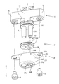
- the connector 1 of this embodiment is a waterproof type that is attached to one end of two wires 2L and 2R that make up a harness and is connected to a device (not shown) such as an inverter.
- the connector 1 includes a housing 10, a shield bracket 20 (an example of a shield member), a first water blocking member 30, and a second water blocking member 40, as shown in FIG. 1 (A).
- Wires 2L, 2R are disposed inside the housing 10 by insert molding, and terminal fittings 3, 3 connected to the device side are attached to one end of each of the wires 2L, 2R, and the other end is a shield It derives from the side where the bracket 20 is disposed.
- the wires 2L and 2R may be referred to as the wire 2.
- the side where the terminal metal fitting 3 is connected to the electric wire 2 will be described as the front, and the side where the electric wire 2 is derived from the housing 10 as the rear.
- the housing 10 includes a wire insertion portion 11 and a pair of attachment receiving portions 16 projecting laterally from the wire insertion portion 11.
- the nuts 4 are embedded in the pair of attachment receiving portions 16 in a form of being opened rearward by insert molding.
- the wire insertion portion 11 is shaped so as to protrude rearward than the attachment receiving portion 16, and the protruding portion is a wire lead-out portion 12.
- the wire lead-out portion 12 has an oval shape as viewed from the rear. As shown in FIG. 3, a part of the outer peripheral surface 12 ⁇ / b> A of the wire lead-out portion 12 is a fitting groove 13 having a shape which is recessed so as to have a smaller diameter than the other.
- the wire lead-out portion 12 is formed with two wire lead-out holes 14L, 14R through which one of the wires 2L, 2R can be inserted.
- Each of the wire lead holes 14L and 14R has a circular hole shape and extends in the wire insertion portion 11 back and forth, and opens in the wire lead surface 15 which is the rear end of the wire lead portion 12.
- the wire lead-out surface 15 is a flat surface orthogonal to an axis extending in the lead-out direction of the wire 2.
- the electric wires 2L and 2R are respectively inserted into the electric wire lead-out holes 14L and 14R and are drawn rearward from the electric wire lead-out surface 15, as shown by imaginary lines in FIG.
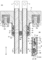
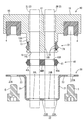
- the shield bracket 20 is a member which is formed of a metal material, covers the wire lead-out portion 12 of the housing 10 and shields the water while shielding the same. As shown in FIG. 2, the shield bracket 20 is configured of a water blocking peripheral wall portion 21, a water blocking holding portion 22, and an attachment portion 23.
- the water blocking peripheral wall portion 21 is a hollow cylindrical body having an oval shape when viewed from the rear.
- the water stop holding portion 22 is provided at the rear end of the water stop peripheral wall portion 21.
- the water blocking holding portion 22 is a frame-shaped collective holding portion 22A extending in the diameter reducing direction from the rear end of the water blocking peripheral wall portion 21 and an electric wire provided along the center line in the left and right direction of the collective holding portion 22A.
- a holding unit 22B a holding unit 22B.
- the collective holding portion 22A and the inter-electric wire holding portion 22B form two holding openings 24L and 24R as shown in FIG.
- the mounting portion 23 is shaped to extend laterally from the front end of the water blocking peripheral wall portion 21.
- Each mounting portion 23 is provided with mounting holes 23A one by one, penetrating through the front and back.
- the first water blocking member 30 is formed of an elastically deformable synthetic resin, and as shown in FIG. 2, has an oval annular shape corresponding to the fitting groove 13 as viewed from the rear. As shown in FIG. 3, on the inner circumferential surface of the first water blocking member 30, two inner circumferential ribs 32 projecting in the diameter reducing direction are formed over the entire circumference. On the outer peripheral surface of the first water blocking member 30, a single first outer peripheral rib 31 projecting in the radial direction is formed over the entire periphery.
- the second water blocking member 40 is formed of an elastically deformable synthetic resin, and as shown in FIG. 2, has an oblong plate shape corresponding to the wire lead-out surface 15 as viewed from the rear.
- the front and back surfaces of the second water blocking member 40 are flat.
- the second water blocking member 40 is formed with two circular through holes 43L and 43R penetrating from the front surface to the rear surface.
- a region surrounding the two through holes 43L and 43R collectively is referred to as a collective surrounding portion 44A
- a portion between the through holes 43L and the through holes 43R is referred to as an inter-wire portion 44B.
- a single second outer peripheral rib 41 is formed on the outer peripheral surface of the second water blocking member 40 so as to protrude in the radial direction over the entire periphery.
- the shield bracket 20 is attached to the housing 10 by inserting the bolts 5 into the attachment holes 23A and screwing the nuts 4.
- the water blocking peripheral wall portion 21 covers the outer peripheral surface 12A and the fitting groove 13 with a gap from the outer peripheral surface 12A of the wire lead-out portion 12.
- the water blocking peripheral wall portion 21 is disposed to extend rearward from the wire lead-out surface 15, and the water blocking holding portion 22 is disposed at a rear end with a gap from the wire lead-out surface 15 of the housing 10.
- the first water blocking member 30 is fitted into the fitting groove 13 and the electric wire lead-out portion 12 of the housing 10 and the water blocking peripheral wall portion 21 of the shield bracket 20 Is sandwiched between
- Each inner circumferential rib 32 is in close contact with the bottom surface 13B of the fitting groove 13 over the entire circumference
- the first outer circumferential rib 31 is in close contact with the inner circumferential surface 21A of the waterproof peripheral wall portion 21 over the entire circumference.
- the electric wires 2L and 2R drawn from the electric wire lead-out surface 15 are respectively press-fit into the through holes 43L and 43R of the second water blocking member 40 and drawn backward, and further pass through the holding openings 24L and 24R of the shield bracket 20. It extends backwards.
- the second water blocking member 40 is sandwiched between the electric wire 2 and the water blocking circumferential wall portion 21.
- the through holes 43L, 43R are in close contact with the electric wires 2L, 2R over the entire circumference, and the second outer peripheral rib 41 is in close contact with the water blocking peripheral wall portion 21 over the entire circumference.
- the wire lead-out surface 15 is surrounded by the water blocking peripheral wall portion 21 of the shield bracket 20 over the entire circumference.
- the first water blocking member 30 closes the gap with the outer circumferential surface 12 A of the electric wire lead-out portion 12 in a fluid tight manner on the front side of the electric wire lead-out surface 15.
- the second water blocking member 40 closes the gap with the electric wire 2 in a fluid-tight manner. That is, the wire lead-out surface 15 is accommodated in the water blocking area isolated from the outer water and the like.
- the second water blocking member 40 is disposed between the water blocking portion 22 and the wire outlet surface 15, and the front surface is opposed to the wire outlet surface 15 with a gap, and the rear surface is in the water retaining portion 22. It is arranged in a state of facing each other through a gap. When the rear surface of the second water blocking member 40 abuts on the water blocking holding portion 22 from the front, the rearward displacement of the second water blocking member 40 is restricted.
- the collective holding portion 22A is opposed to the collective surrounding portion 44A of the rear surface of the second water blocking member 40, and as shown in FIG. 1 (A), An inter-electric wire holding portion 22B is opposed to the inter-electric wire portion 44B.
- the connector 1 includes the housing 10 having the wire lead-out surface 15 from which the electric wire 2 is drawn, the shield member (shield bracket 20) disposed outside the housing 10, the housing 10 and the shield member A first water blocking member 30 held between 20 and in close contact therewith, and a second stop held between the wire 2 led out from the wire lead-out surface 15 and the shield member 20 and in close contact with these A water member 40 is provided, and the shield member 20 has a water stop portion 22 for holding the second water stop member 40 with the electric wire lead-out surface 15.
- the electric wire in the housing 10 is stopped by the water stop between the housing 10 and the shield member 20 by the first water stop member 30 and the electric wire 2 and the shield member 20 by the second water stop member 40. Since the outlet surface 15 is in the water blocking area, it is possible to prevent the entry of water or the like into the housing 10. Further, since the second water blocking member 40 is held between the wire lead-out surface 15 and the water blocking holding portion 22 of the shield member 20, it is not necessary to separately provide a member for holding the second water blocking member 40. Also, the connector 1 can be miniaturized accordingly.
- a plurality of electric wires 2L and 2R are led out from the electric wire lead-out surface 15, and the second water blocking member 40 is a plurality of through holes 43L into which one of the plurality of electric wires 2L and 2R is inserted.
- 43R, and the water blocking holding portion 22 is a collective holding portion 22A disposed around the plurality of electric wires 2L and 2R collectively and an inter-electric wire holding portion disposed between the plurality of electric wires 2L and 2R 22 B is provided.
- the second water blocking member 40 In the configuration in which the second water blocking member 40 is held between the wire lead-out surface 15 and the collective holding portion 22A, when the second water stopping member 40 is pressed by the collective holding portion 22A, the plurality of electric wires 2L and 2R The part between the two is deformed so as to escape from the pressing force, and it tends to be in a state of jumping out from the normal position. According to the above configuration, since the second water blocking member 40 is also held between the wire lead-out surface 15 and the inter-wire holding portion 22B, the second water blocking member can be held at the regular position.
- the electric wire 2 and the housing 10 are integrally formed by insert molding.
- the gap between the wire 2 and the housing 10 allows water and the like. According to the above configuration, since the wire lead-out surface 15 is disposed in the water blocking area, it is possible to prevent water or the like from entering from the gap between the wire 2 and the housing 10.
- the number of electric wires 2L and 2R is not limited to this and may be only one or three or more. .
- the wire lead-out surface 15 of the housing 10 and the second water blocking member 40 are arranged to face each other, but the wire lead-out surface and the second water blocking member do not necessarily face each other It does not have to be.
- another member may be disposed between the wire outlet surface and the second water blocking member.
- the shield bracket 20 is fixed to the housing 10.
- the shield bracket destination is not limited thereto.
- the shield bracket 20 is fixed to the housing of the device to which the connector is attached It is also good.
- the wire 2 is disposed in the housing 10 by insert molding, but a through hole may be provided in the wire insertion portion in advance, and the wire may be inserted through the through hole. .
- the wire lead-out portion 12 of the housing 1 is shaped to protrude rearward, but the shape of the wire lead-out portion is not limited to this.
- the wire lead-out surface is flush with the rear surface of the mounting receiving portion May be provided. In that case, the first water blocking member may be held between the mounting portion of the shield bracket and the mounting receiving portion.
Landscapes
- Connector Housings Or Holding Contact Members (AREA)
- Details Of Connecting Devices For Male And Female Coupling (AREA)
Priority Applications (2)
| Application Number | Priority Date | Filing Date | Title |
|---|---|---|---|
| US16/959,181 US11201432B2 (en) | 2018-01-16 | 2019-01-15 | Connector |
| CN201980007366.2A CN111656622B (zh) | 2018-01-16 | 2019-01-15 | 连接器 |
Applications Claiming Priority (2)
| Application Number | Priority Date | Filing Date | Title |
|---|---|---|---|
| JP2018004903A JP6919577B2 (ja) | 2018-01-16 | 2018-01-16 | コネクタ |
| JP2018-004903 | 2018-01-16 |
Publications (1)
| Publication Number | Publication Date |
|---|---|
| WO2019142762A1 true WO2019142762A1 (ja) | 2019-07-25 |
Family
ID=67302285
Family Applications (1)
| Application Number | Title | Priority Date | Filing Date |
|---|---|---|---|
| PCT/JP2019/000858 Ceased WO2019142762A1 (ja) | 2018-01-16 | 2019-01-15 | コネクタ |
Country Status (4)
| Country | Link |
|---|---|
| US (1) | US11201432B2 (https=) |
| JP (1) | JP6919577B2 (https=) |
| CN (1) | CN111656622B (https=) |
| WO (1) | WO2019142762A1 (https=) |
Cited By (1)
| Publication number | Priority date | Publication date | Assignee | Title |
|---|---|---|---|---|
| US20220189662A1 (en) * | 2020-12-16 | 2022-06-16 | Yazaki Corporation | Connector for device |
Families Citing this family (3)
| Publication number | Priority date | Publication date | Assignee | Title |
|---|---|---|---|---|
| JP6826519B2 (ja) * | 2017-11-16 | 2021-02-03 | 東海興業株式会社 | 組み立て体 |
| JP7494775B2 (ja) * | 2021-03-25 | 2024-06-04 | 住友電装株式会社 | コネクタ |
| JP7384880B2 (ja) | 2021-10-19 | 2023-11-21 | 矢崎総業株式会社 | コネクタ |
Citations (5)
| Publication number | Priority date | Publication date | Assignee | Title |
|---|---|---|---|---|
| JP2012199051A (ja) * | 2011-03-22 | 2012-10-18 | Yazaki Corp | シールドコネクタ |
| JP2014029780A (ja) * | 2012-07-31 | 2014-02-13 | Yazaki Corp | シールドコネクタ構造 |
| JP2014146435A (ja) * | 2013-01-28 | 2014-08-14 | Yazaki Corp | コネクタ構造 |
| JP2016119186A (ja) * | 2014-12-19 | 2016-06-30 | 矢崎総業株式会社 | 防水コネクタ用ゴム栓および防水コネクタ |
| JP2017157417A (ja) * | 2016-03-02 | 2017-09-07 | 住友電装株式会社 | 防水コネクタ |
Family Cites Families (15)
| Publication number | Priority date | Publication date | Assignee | Title |
|---|---|---|---|---|
| JPH09161893A (ja) * | 1995-12-04 | 1997-06-20 | Yazaki Corp | コネクタの接続構造 |
| JP4082602B2 (ja) * | 2003-10-24 | 2008-04-30 | 矢崎総業株式会社 | シールド電線の接続構造 |
| US7029328B1 (en) * | 2005-02-04 | 2006-04-18 | J.S.T. Corporation | Waterproof electrical connector |
| JP5711594B2 (ja) * | 2011-04-14 | 2015-05-07 | 矢崎総業株式会社 | シールドコネクタ |
| JP5917013B2 (ja) * | 2011-04-19 | 2016-05-11 | 住友電装株式会社 | シールドコネクタ |
| JP5952607B2 (ja) * | 2012-03-27 | 2016-07-13 | 矢崎総業株式会社 | 防水型シールドコネクタ |
| JP5931616B2 (ja) * | 2012-07-09 | 2016-06-08 | タイコエレクトロニクスジャパン合同会社 | 防水型コネクタ及びワイヤシール |
| JP2014086350A (ja) * | 2012-10-25 | 2014-05-12 | Sumitomo Wiring Syst Ltd | シールドコネクタ |
| JP5990454B2 (ja) * | 2012-12-25 | 2016-09-14 | 矢崎総業株式会社 | シールドコネクタ構造 |
| JP6047446B2 (ja) * | 2013-02-15 | 2016-12-21 | 矢崎総業株式会社 | 電線の端子接続構造 |
| JP6234034B2 (ja) * | 2013-02-20 | 2017-11-22 | 矢崎総業株式会社 | シールドコネクタ構造 |
| JP6311938B2 (ja) * | 2015-03-02 | 2018-04-18 | 株式会社オートネットワーク技術研究所 | 多芯ケーブルのシール構造 |
| JP6204394B2 (ja) * | 2015-03-18 | 2017-09-27 | 矢崎総業株式会社 | ストレート型コネクタ |
| JP6604516B2 (ja) | 2016-03-08 | 2019-11-13 | 住友電装株式会社 | 防水コネクタ |
| MX392117B (es) * | 2016-07-15 | 2025-03-21 | Hirschmann Automotive Gmbh | Contacto de clavija resistente a altas temperaturas para detector de detonaciones de motor de combustion interna. |
-
2018
- 2018-01-16 JP JP2018004903A patent/JP6919577B2/ja active Active
-
2019
- 2019-01-15 WO PCT/JP2019/000858 patent/WO2019142762A1/ja not_active Ceased
- 2019-01-15 CN CN201980007366.2A patent/CN111656622B/zh active Active
- 2019-01-15 US US16/959,181 patent/US11201432B2/en active Active
Patent Citations (5)
| Publication number | Priority date | Publication date | Assignee | Title |
|---|---|---|---|---|
| JP2012199051A (ja) * | 2011-03-22 | 2012-10-18 | Yazaki Corp | シールドコネクタ |
| JP2014029780A (ja) * | 2012-07-31 | 2014-02-13 | Yazaki Corp | シールドコネクタ構造 |
| JP2014146435A (ja) * | 2013-01-28 | 2014-08-14 | Yazaki Corp | コネクタ構造 |
| JP2016119186A (ja) * | 2014-12-19 | 2016-06-30 | 矢崎総業株式会社 | 防水コネクタ用ゴム栓および防水コネクタ |
| JP2017157417A (ja) * | 2016-03-02 | 2017-09-07 | 住友電装株式会社 | 防水コネクタ |
Cited By (2)
| Publication number | Priority date | Publication date | Assignee | Title |
|---|---|---|---|---|
| US20220189662A1 (en) * | 2020-12-16 | 2022-06-16 | Yazaki Corporation | Connector for device |
| US11682503B2 (en) * | 2020-12-16 | 2023-06-20 | Yazaki Corporation | Connector for device |
Also Published As
| Publication number | Publication date |
|---|---|
| CN111656622A (zh) | 2020-09-11 |
| CN111656622B (zh) | 2022-03-01 |
| JP2019125470A (ja) | 2019-07-25 |
| JP6919577B2 (ja) | 2021-08-18 |
| US20200343668A1 (en) | 2020-10-29 |
| US11201432B2 (en) | 2021-12-14 |
Similar Documents
| Publication | Publication Date | Title |
|---|---|---|
| US7618286B2 (en) | Shield connector | |
| JP5790492B2 (ja) | 電線固定部材 | |
| US7097498B2 (en) | Connector for apparatus | |
| WO2019142762A1 (ja) | コネクタ | |
| JP2012128966A (ja) | 防水コネクタ | |
| JP2013097898A (ja) | シール部材 | |
| EP2768088B1 (en) | Shield connector | |
| US10811818B2 (en) | Wire holding structure | |
| JP2017162594A (ja) | 防水コネクタ | |
| JP6024611B2 (ja) | コネクタ | |
| JP2008204960A (ja) | 防水コネクタ | |
| JP4417274B2 (ja) | シールドコネクタ | |
| US9425538B2 (en) | Cable connector assembly with a snap ring | |
| JP2011009108A (ja) | シールドコネクタ | |
| JP5229580B2 (ja) | シールドコネクタ | |
| JP5840175B2 (ja) | コネクタ、及びコネクタユニット | |
| JP6194848B2 (ja) | コネクタ | |
| JP7230711B2 (ja) | コネクタ | |
| JP2014022062A (ja) | 防水コネクタ | |
| CN111542972B (zh) | 连接器 | |
| JP5772580B2 (ja) | 電線固定部材 | |
| JP2013084510A (ja) | シールドシェルおよびシールドコネクタ | |
| JP2017045635A (ja) | シール付きリテーナ | |
| JP2018078031A (ja) | 機器用コネクタ | |
| JP2014022061A (ja) | 防水コネクタ |
Legal Events
| Date | Code | Title | Description |
|---|---|---|---|
| 121 | Ep: the epo has been informed by wipo that ep was designated in this application |
Ref document number: 19741537 Country of ref document: EP Kind code of ref document: A1 |
|
| NENP | Non-entry into the national phase |
Ref country code: DE |
|
| 122 | Ep: pct application non-entry in european phase |
Ref document number: 19741537 Country of ref document: EP Kind code of ref document: A1 |