WO2019142355A1 - 段付きドリル及び段付きドリルの製造方法 - Google Patents
段付きドリル及び段付きドリルの製造方法 Download PDFInfo
- Publication number
- WO2019142355A1 WO2019142355A1 PCT/JP2018/001761 JP2018001761W WO2019142355A1 WO 2019142355 A1 WO2019142355 A1 WO 2019142355A1 JP 2018001761 W JP2018001761 W JP 2018001761W WO 2019142355 A1 WO2019142355 A1 WO 2019142355A1
- Authority
- WO
- WIPO (PCT)
- Prior art keywords
- cutting edge
- grinding
- small diameter
- groove
- diameter portion
- Prior art date
Links
Images


Classifications
-
- B—PERFORMING OPERATIONS; TRANSPORTING
- B24—GRINDING; POLISHING
- B24B—MACHINES, DEVICES, OR PROCESSES FOR GRINDING OR POLISHING; DRESSING OR CONDITIONING OF ABRADING SURFACES; FEEDING OF GRINDING, POLISHING, OR LAPPING AGENTS
- B24B3/00—Sharpening cutting edges, e.g. of tools; Accessories therefor, e.g. for holding the tools
- B24B3/24—Sharpening cutting edges, e.g. of tools; Accessories therefor, e.g. for holding the tools of drills
- B24B3/242—Sharpening cutting edges, e.g. of tools; Accessories therefor, e.g. for holding the tools of drills of step drills
-
- B—PERFORMING OPERATIONS; TRANSPORTING
- B23—MACHINE TOOLS; METAL-WORKING NOT OTHERWISE PROVIDED FOR
- B23B—TURNING; BORING
- B23B51/00—Tools for drilling machines
- B23B51/009—Stepped drills
-
- B—PERFORMING OPERATIONS; TRANSPORTING
- B23—MACHINE TOOLS; METAL-WORKING NOT OTHERWISE PROVIDED FOR
- B23B—TURNING; BORING
- B23B51/00—Tools for drilling machines
- B23B51/04—Drills for trepanning
-
- B—PERFORMING OPERATIONS; TRANSPORTING
- B23—MACHINE TOOLS; METAL-WORKING NOT OTHERWISE PROVIDED FOR
- B23B—TURNING; BORING
- B23B51/00—Tools for drilling machines
- B23B51/10—Bits for countersinking
- B23B51/108—Bits for countersinking having a centering drill
-
- B—PERFORMING OPERATIONS; TRANSPORTING
- B24—GRINDING; POLISHING
- B24B—MACHINES, DEVICES, OR PROCESSES FOR GRINDING OR POLISHING; DRESSING OR CONDITIONING OF ABRADING SURFACES; FEEDING OF GRINDING, POLISHING, OR LAPPING AGENTS
- B24B19/00—Single-purpose machines or devices for particular grinding operations not covered by any other main group
- B24B19/02—Single-purpose machines or devices for particular grinding operations not covered by any other main group for grinding grooves, e.g. on shafts, in casings, in tubes, homokinetic joint elements
- B24B19/04—Single-purpose machines or devices for particular grinding operations not covered by any other main group for grinding grooves, e.g. on shafts, in casings, in tubes, homokinetic joint elements for fluting drill shanks
-
- B—PERFORMING OPERATIONS; TRANSPORTING
- B23—MACHINE TOOLS; METAL-WORKING NOT OTHERWISE PROVIDED FOR
- B23B—TURNING; BORING
- B23B2251/00—Details of tools for drilling machines
- B23B2251/04—Angles, e.g. cutting angles
-
- B—PERFORMING OPERATIONS; TRANSPORTING
- B23—MACHINE TOOLS; METAL-WORKING NOT OTHERWISE PROVIDED FOR
- B23B—TURNING; BORING
- B23B2251/00—Details of tools for drilling machines
- B23B2251/08—Side or plan views of cutting edges
- B23B2251/082—Curved cutting edges
-
- B—PERFORMING OPERATIONS; TRANSPORTING
- B23—MACHINE TOOLS; METAL-WORKING NOT OTHERWISE PROVIDED FOR
- B23B—TURNING; BORING
- B23B2251/00—Details of tools for drilling machines
- B23B2251/20—Number of cutting edges
- B23B2251/202—Three cutting edges
-
- B—PERFORMING OPERATIONS; TRANSPORTING
- B23—MACHINE TOOLS; METAL-WORKING NOT OTHERWISE PROVIDED FOR
- B23B—TURNING; BORING
- B23B2251/00—Details of tools for drilling machines
- B23B2251/24—Overall form of drilling tools
-
- Y—GENERAL TAGGING OF NEW TECHNOLOGICAL DEVELOPMENTS; GENERAL TAGGING OF CROSS-SECTIONAL TECHNOLOGIES SPANNING OVER SEVERAL SECTIONS OF THE IPC; TECHNICAL SUBJECTS COVERED BY FORMER USPC CROSS-REFERENCE ART COLLECTIONS [XRACs] AND DIGESTS
- Y10—TECHNICAL SUBJECTS COVERED BY FORMER USPC
- Y10T—TECHNICAL SUBJECTS COVERED BY FORMER US CLASSIFICATION
- Y10T408/00—Cutting by use of rotating axially moving tool
- Y10T408/89—Tool or Tool with support
- Y10T408/905—Having stepped cutting edges
- Y10T408/906—Axially spaced
Definitions
- the present invention relates to a stepped drill and a method of manufacturing a stepped drill, and more particularly to a stepped drill and a method of manufacturing a stepped drill capable of improving cutting performance of a cutting edge of a stepped portion.
- a stepped drill having a tapered step which connects a small diameter portion and a large diameter portion and in which a cutting edge is formed.
- a stepped drill as described in Patent Document 1, when a fixed lead groove is formed by grinding once from the small diameter portion to the step portion, the cutting edge of the step portion faces the rotation direction side of the drill It becomes easy to be formed in convex curve shape. Therefore, the radial direction rake angle of the cutting edge of the step becomes a large negative angle, and the cutting performance of the cutting edge of the step decreases.
- Japanese Utility Model Publication No. 05-053817 (for example, paragraph 0006, FIG. 5) JP, 2003-025125, A (for example, paragraph 0017, FIG. 1)
- FIG. 4A is a schematic view showing a conventional method for grinding the groove 205 in the stepped drill 201
- FIG. 4B is a partially enlarged side view of the conventional stepped drill 201. As shown in FIG.
- the cutting edge 230 of the stepped portion 203 is formed in a convex curved shape facing the rotation direction side of the stepped drill 201, and the radial direction rake angle of the cutting edge 230 of the stepped portion 203. Tends to be at a larger negative angle.
- a countersink a chamfer of a hole machined by the small diameter portion 202
- a surface roughness defect of the chamfered portion or a peeling of the surface occurs. That is, in the conventional stepped drill 201 in which the cutting edge of the small diameter portion 202 has a convex blade portion, there is a problem that the cutting performance of the cutting edge 230 of the stepped portion 203 is lowered.
- the present invention has been made to solve the problems described above, and it is an object of the present invention to provide a stepped drill and a method of manufacturing the stepped drill which can improve the cutting performance of the cutting edge of the step. There is.
- the stepped drill of the present invention has a tapered portion having a small diameter portion having a first cutting edge at its tip end and an axial rear end of the small diameter portion and a second cutting edge.
- a step portion and a groove formed by a constant lead from the small diameter portion to the step portion are provided, and the first cutting edge is formed on the outer peripheral end side and the rotational direction of the small diameter portion
- a first grinding portion that forms a region including the second cutting edge of the step portion, and the groove is a heel side of the step portion with respect to the first grinding portion.
- a second grinding portion forming an area, and the convex blade portion is formed by the intersection of the first grinding portion and the second grinding portion.
- the first cutting edge is formed on the outer peripheral end side and has a convex shape convex in the rotation direction of the small diameter portion Since the blade portion is provided, the cutting performance (sharpness) of the first cutting edge is improved.
- the groove is provided with a first grinding portion forming a region including the second cutting edge of the step, and a second grinding portion forming a region on the heel side of the step than the first grinding portion.
- the first grinding portion and the second grinding portion are By making it cross and grind, a convex-shaped edge part can be formed in the 1st cutting edge. That is, the second cutting edge can be formed into a desired shape during grinding of the first grinding portion (in the first step), and the grindstone interferes with the second cutting edge during grinding of the second grinding portion (in the second step) Can be suppressed, so that it is possible to suppress that the radial direction rake angle of the second cutting edge becomes a large negative angle. Therefore, there is an effect that the cutting performance of the second cutting edge can be improved.
- the second cutting edge is formed substantially straight toward the outer peripheral end, there is an effect that the cutting performance of the second cutting edge can be improved.
- substantially linear is defined as including a configuration in which the second cutting edge is formed in a gently curved shape that is convex in the rotational direction of the step.
- the radial direction rake angle on the outer peripheral end side of the second cutting edge is set to an angle (for example, -20 °) or more at which reduction in cutting performance can be suppressed. It should be set.
- the second step is performed after the first step.
- the cutting edge can be easily formed. That is, if the second step is performed first, it is necessary to adjust the dimensions of the land width (the width from the leading edge to the heel) while forming the second cutting edge in the first step. By doing this, it is not necessary to adjust the dimensions of the land width while forming the second cutting edge. Therefore, since the second cutting edge can be easily formed into a desired shape, there is an effect that the cutting performance of the second cutting edge can be improved.
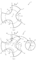
- FIG. 1C is a cross-sectional view of the stepped drill taken along line Ic-Ic in FIG.
- FIG. 2A is a cross-sectional view of a stepped drill taken along line IIa-IIa of FIG. 1A
- FIG. 2B is a partially enlarged side view schematically showing the stepped drill.
- (A) is sectional drawing of the step drill which shows the state in which the primary groove was ground
- (b) is sectional drawing of the step drill which shows the method of grinding a secondary groove.
- A) is a schematic diagram which shows the conventional method of grinding a groove
- (b) is the elements on larger scale side view of the conventional stepped drill.
- FIG. 1 (a) is a side view schematically showing a stepped drill 1 according to an embodiment of the present invention.
- the stepped drill 1 is a cutting tool for drilling and chamfering a workpiece by a rotational force transmitted from a processing machine (for example, a machining center).
- a processing machine for example, a machining center.
- WC etc. is formed from pressure cemented cemented carbide.
- the stepped drill 1 is connected to the small diameter portion 2 and the step portion 3 connected to the rear end (the end on the right side of FIG. 1A) of the small diameter portion 2 and to the rear end of the step 3
- a large diameter portion 4 formed to have a diameter larger than that of the small diameter portion 2, and a spiral groove 5 formed on the outer peripheral surface of the small diameter portion 2, the stepped portion 3 and the large diameter portion 4 (FIG. ))
- a large diameter portion 4 formed to have a diameter larger than that of the small diameter portion 2
- a spiral groove 5 formed on the outer peripheral surface of the small diameter portion 2, the stepped portion 3 and the large diameter portion 4 (FIG. )
- the small diameter portion 2, the step portion 3, and the large diameter portion 4 are integrally formed in the direction of the axis O forming their axis, and the diameter of the step portion 3 is the diameter of the small diameter portion 2 (in this embodiment , 5 mm) to the diameter of the large diameter portion 4 (8 mm in the present embodiment).
- the small diameter portion 2 is a portion to be drilled in the workpiece, and the tip angle thereof is set to 140 °.
- the stepped portion 3 is a portion where a hole formed by the small diameter portion 2 is bored or a hole having a diameter larger than that of the small diameter portion 2 is processed, and the step angle thereof is set to 60 °.
- the large diameter portion 4 is configured as a shank in which the groove 5 is not formed in a partial region on the rear end side, and the region is held by the processing machine.
- the groove 5 (see FIG. 1 (b)) constitutes a rake surface of the first cutting edge 20 and the second cutting edge 30 (see FIG. 2) described later, and for discharging chips during processing of the workpiece. It is a site.
- the groove 5 is a groove recessed toward the axis O on the outer peripheral surface of the small diameter portion 2, the step portion 3 and the large diameter portion 4, and a spiral shape of a constant lead from the small diameter portion 2 to the large diameter portion 4 Is formed.
- FIG. 1 (b) is a cross-sectional view of the stepped drill 1 taken along line Ib-Ib of FIG. 1 (a).
- FIG. 1 (b) is a cross section (hereinafter referred to as “140 ° cross section”) cut along the same angle as the tip angle (140 °) of the small diameter portion 2, and It is the figure which projected the cross section which followed the ridgeline on a plane. Further, hatching is omitted in FIG. 1 (b) to simplify the drawing, and the same applies to FIG. 1 (c) and thereafter.
- three first cutting edges 20 are formed at the ridge line portion where the tip end surface (a flank surface) of the small diameter portion 2 intersects with the groove 5, and these three first cutting edges 20 are provided at equal angular intervals about the axis O.
- the first cutting edge 20 is formed on the outer peripheral end side thereof and has a convex blade portion 20 a convex in the rotational direction R of the small diameter portion 2.
- An inner peripheral side of the tip end of the convex blade portion 20 a in the first cutting edge 20 is formed in a curved shape that is recessed toward the rear side in the rotation direction R of the small diameter portion 2.
- the radial direction rake angle of the region from the tip of the convex blade 20a facing the rotation direction R side to the outer peripheral corner 20b of the first cutting edge 20 is a negative angle (this embodiment) Is set to -20 °). That is, the tip of the convex blade portion 20a is formed so as to protrude toward the rotational direction R side from the straight line connecting the axis O and the outer peripheral corner 20b. As a result, it is possible to suppress the occurrence of chipping or chipping in the outer peripheral corner 20b at the time of hole processing by the first cutting edge 20, and to improve the sharpness of the first cutting edge 20.
- FIG. 1 (c) is a cross-sectional view of the stepped drill 1 taken along line Ic-Ic in FIG. 1 (a).
- the 140 degree cross section of the step part 3 is shown in figure.
- a partial region on the inner peripheral side has the same shape as the cross-sectional shape in the small diameter portion 2, and such a region corresponds to the broken line D in FIG.
- the shape of the groove 5 in the 140 ° cross section of the small diameter portion 2 is the same shape as the region surrounded by the broken line D in FIG. 1C.
- the groove 5 constitutes a first grinding portion 50 which constitutes a region on the leading edge 6 side of the step 3 and a region which is closer to the heel 7 than the first grinding portion 50.
- a second grinding unit 51 a second grinding unit 51.
- the groove 5 is formed in a curved shape that is recessed toward the axis O by the first grinding portion 50 and the second grinding portion 51, but the intersection point P of the first grinding portion 50 and the second grinding portion 51 has a rotational direction R It is formed in convex shape toward.
- the intersection point P is formed slightly inward of the broken line D, and this intersection point P forms a convex blade 20a (see FIG. 1B) of the first cutting edge 20 when the groove 5 is ground. It is a part that appears in
- the cross-sectional shape (convex shape) of the intersection point P in the 140 ° cross section becomes substantially the same as the shape of the convex blade portion 20a in the 140 ° cross section (an enlarged portion in FIG. 1 (b) and FIG. 1 (c) reference).
- “approximately” the same shape means that the chamfered shape is applied to the convex blade portion 20a after the formation of the groove 5, so that the actual shape of the convex blade portion 20a and the shape of the intersection point P slightly differ.
- ridge lines of an intersection point P having substantially the same shape as the convex blade portion 20 a are formed in the groove 5 from the small diameter portion 2 to the step portion 3.
- FIG. 2 (a) is sectional drawing of the stepped drill 1 in the IIa-IIa line
- FIG.2 (b) is the partial enlarged side view which showed the stepped drill 1 typically. is there.
- FIG. 2A is a cross section (hereinafter referred to as “60 ° cross section”) cut along the step angle (60 °) of the step portion 3 and a cross section along the second cutting edge 30 ridge line Is projected on a plane.
- three second cutting edges 30 are formed at the ridge line portion where the tip end surface (a flank surface) of the step portion 3 and the groove 5 intersect, and these three second cutting edges 30 have an axis It is provided at equal angular intervals about O.
- the second cutting edge 30 has a substantially linear shape from the end portion on the inner peripheral side to the outer peripheral end (from the small diameter portion 2 side to the large diameter portion 4 side) in a 60 ° cross section (tip view of the stepped drill 1) Is formed.
- the radial direction rake angle ⁇ of the outer peripheral end of the second cutting edge 30 is It is set to -20 °.
- the cutting edge 230 of the step portion 203 as shown in FIG. 4 is formed in a convex curved shape facing the rotation direction side (the radial direction rake angle of the cutting edge 230 is a large negative angle).
- the second cutting edge 30 performs dishing (chamfering of the hole processed by the first cutting edge 20) as compared with the drill with drill 201, surface roughness defects of the chamfered portion and surface peeling occur. Can be suppressed.
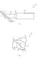
- FIG. 3 (a) is a cross-sectional view of the stepped drill 1 showing a state in which the primary groove G1 is ground
- FIG. 3 (b) is a sectional view of the stepped drill 1 showing a method of grinding the secondary groove G2.
- FIG. 3 the cross-sectional shape of the groove 5 in a 140 ° cross section is illustrated.
- FIG.3 (b) the groove shape of secondary groove G2 is shown in figure by the dashed-two dotted line.
- the method of manufacturing the stepped drill 1 includes a first step (see FIG. 3A) of grinding the primary groove G1 and a second step of grinding the secondary groove G2 (FIG. 3 (FIG. b) see).
- the first step and the second step are steps of forming the first cutting edge 20 and the second cutting edge 30 by forming the groove 5 by grinding with a grindstone (determining the shape of the cutting edge according to the shape of the groove 5) .
- the first step is a step of grinding the primary groove G1 toward the axis O shallower than the desired core thickness to grind a region including the first grinding portion 50 of the groove 5. That is, the primary groove G1 has a portion on the outer peripheral side of the convex blade 20a of the first cutting edge 20 (a region from the tip of the convex cutting blade 20a to the outer peripheral corner 20b) and the entire second cutting blade 30. It is a groove for determining the shape, and is formed in a spiral shape of a fixed lead from the small diameter portion 2 to the step portion 3 (large diameter portion 4).
- the second step performed after the first step is a step of grinding the secondary grinding portion 51 of the groove 5 by grinding the secondary groove G2 deeper toward the axis O than the groove bottom of the primary groove G1.
- the secondary groove G2 is a groove for determining the shape of the first cutting edge 20 on the inner peripheral side of the tip of the convex blade portion 20a, and from the small diameter portion 2 to the step portion 3 (large diameter portion 4). It is formed in a spiral shape of a fixed lead (a lead identical to the primary groove G1).
- the primary groove G1 and the secondary groove G2 are intersected slightly inside the broken line D (curved surface concaved to the rear side in the rotational direction R)
- the convex-shaped convex blade 20a (intersection point P) on the outer peripheral end side of the first cutting edge 20 in the rotational direction R)
- the inner peripheral than the convex blade 20a can be formed in a curved shape (that is, the first cutting edge 20 is a hook-type cutting edge) recessed toward the rear side in the rotational direction R of the small diameter portion 2.
- the grindstone at the time of grinding the secondary groove G2 is the first grinding portion 50 (in the primary groove G1 Interference with the formed one) can be suppressed. Therefore, if the cross-sectional shape of the first grinding portion 50 (primary groove G1) in the 60 ° cross-section is set such that the cutting edge shape of the second cutting edge 30 becomes a desired shape, the second cutting edge 30 is desired.
- the convex blade portion 20 a can be formed on the first cutting edge 20 while being formed into a shape.
- the desired shape of the second cutting edge 30 is preferably a linear shape toward the outer peripheral end, but a configuration may be employed in which only a partial region on the inner peripheral side is formed in a linear shape. That is, in the case where the second cutting edge 30 performs dishing (chamfering of the hole formed by the first cutting edge 20), the entire second cutting edge 30 may not be used.
- the second cutting edge 30 may be formed in a linear shape from the inner circumferential side to the outer circumferential side with a dimension longer than the region where the second step is performed.
- the second cutting edge 30 may be formed not in a completely linear shape but in a gently curved shape that is convex in the rotation direction R.
- the radial direction rake angle of the outer peripheral end of the second cutting edge 30 is an angle (for example, -20 °) or more at which a reduction in cutting performance can be suppressed. It should be set to
- the entire second cutting blade 30 may be formed in a straight line, but it is not a perfect straight line.
- the second cutting edge 30 may be formed in a gently curved shape that is convex in the rotational direction R.
- the radial direction rake angle on the outer peripheral end side of the second cutting edge 30 may be set to an angle (for example, -20 °) or more at which reduction in cutting performance can be suppressed.
- a convex cutting edge at the outer peripheral end of the second cutting edge 30 (a cutting edge having a convex shape in the direction of rotation R) ) May be formed.
- a convex blade portion on the second cutting edge 30 it is possible to suppress the occurrence of chipping or chipping at the outer peripheral end of the second cutting edge 30 at the time of drilling by the second cutting edge 30, and The sharpness of 30 can be improved.
- the shape of the second cutting edge 30 may be formed into a desired shape according to the purpose. Even if the second cutting edge 30 is formed into any shape, the second cutting edge 20a is formed on the first cutting edge 20 if the groove grinding is performed twice as in the present embodiment.
- the desired shape of the two cutting edges 30 can be formed.
- the radial direction rake angle of the second cutting edge 30 can be set to a large angle (for example, -20 ° or more) as compared to the case where the convex blade portion 20a is formed by one groove grinding.
- the primary groove G1 is ground first and then the secondary groove G2 is ground, it is unnecessary to adjust the land width dimension when forming the second cutting edge 30. You can Therefore, as compared with the case where the secondary groove G2 is ground first, the second cutting edge 30 can be easily formed in a desired shape, so the cutting performance of the second cutting edge 30 can be improved.
- the present invention was explained based on the above-mentioned embodiment, the present invention is not limited to the above-mentioned form at all, It is easy to be able to carry out various modification improvement in the range which does not deviate from the meaning of the present invention. It can be guessed.
- the diameter and tip angle of the small diameter portion 2, the step angle of the step 3, the diameter of the large diameter portion 4, the radial rake angle on the outer peripheral side of the convex blade portion 20 a, and the outer peripheral end of the second cutting edge 30 The numerical value of the radial direction rake angle is an example and can be set as appropriate.
- the present invention is not necessarily limited thereto.
- the primary groove G1 may be ground after the secondary groove G2. good.
- the second cutting edge 30 can be formed into a desired shape by the primary groove G1 while forming the convex blade portion 20a at the intersection of the secondary groove G2 and the primary groove G1.
Landscapes
- Engineering & Computer Science (AREA)
- Mechanical Engineering (AREA)
- Drilling Tools (AREA)
Priority Applications (6)
| Application Number | Priority Date | Filing Date | Title |
|---|---|---|---|
| US16/094,313 US11103933B2 (en) | 2018-01-22 | 2018-01-22 | Step drill and manufacturing method for step drill |
| EP18773065.0A EP3536432B1 (de) | 2018-01-22 | 2018-01-22 | Stufenbohrer und herstellungsverfahren für stufenbohrer |
| JP2018539440A JP6576573B1 (ja) | 2018-01-22 | 2018-01-22 | 段付きドリル及び段付きドリルの製造方法 |
| CN201880001172.7A CN110461515B (zh) | 2018-01-22 | 2018-01-22 | 阶梯钻以及阶梯钻的制造方法 |
| KR1020187038021A KR102178656B1 (ko) | 2018-01-22 | 2018-01-22 | 스텝이 형성된 드릴 및 스텝이 형성된 드릴의 제조 방법 |
| PCT/JP2018/001761 WO2019142355A1 (ja) | 2018-01-22 | 2018-01-22 | 段付きドリル及び段付きドリルの製造方法 |
Applications Claiming Priority (1)
| Application Number | Priority Date | Filing Date | Title |
|---|---|---|---|
| PCT/JP2018/001761 WO2019142355A1 (ja) | 2018-01-22 | 2018-01-22 | 段付きドリル及び段付きドリルの製造方法 |
Publications (1)
| Publication Number | Publication Date |
|---|---|
| WO2019142355A1 true WO2019142355A1 (ja) | 2019-07-25 |
Family
ID=67301637
Family Applications (1)
| Application Number | Title | Priority Date | Filing Date |
|---|---|---|---|
| PCT/JP2018/001761 WO2019142355A1 (ja) | 2018-01-22 | 2018-01-22 | 段付きドリル及び段付きドリルの製造方法 |
Country Status (6)
| Country | Link |
|---|---|
| US (1) | US11103933B2 (de) |
| EP (1) | EP3536432B1 (de) |
| JP (1) | JP6576573B1 (de) |
| KR (1) | KR102178656B1 (de) |
| CN (1) | CN110461515B (de) |
| WO (1) | WO2019142355A1 (de) |
Families Citing this family (1)
| Publication number | Priority date | Publication date | Assignee | Title |
|---|---|---|---|---|
| US11260459B2 (en) * | 2020-04-30 | 2022-03-01 | The Boeing Company | Tools and methods for forming aligned holes from near full-sized holes |
Citations (6)
| Publication number | Priority date | Publication date | Assignee | Title |
|---|---|---|---|---|
| JP2003025125A (ja) | 2001-07-10 | 2003-01-29 | Mitsubishi Materials Corp | ドリル |
| JP2003334709A (ja) * | 2002-05-13 | 2003-11-25 | Nippon Choko Kk | 段付ドリル |
| JP2010131736A (ja) * | 2008-12-08 | 2010-06-17 | Kyowa Seiko Kk | 穿孔ドリル及び穿孔ドリルの加工方法 |
| WO2013179417A1 (ja) * | 2012-05-30 | 2013-12-05 | オーエスジー株式会社 | 3枚刃ドリル |
| JP2013252610A (ja) * | 2006-10-13 | 2013-12-19 | Kennametal Inc | ドリル工具用ビット |
| WO2015118684A1 (ja) * | 2014-02-10 | 2015-08-13 | 栗田工機株式会社 | ドリル及び穴明け方法 |
Family Cites Families (21)
| Publication number | Priority date | Publication date | Assignee | Title |
|---|---|---|---|---|
| US1747117A (en) * | 1927-04-01 | 1930-02-11 | Dayton W Klein | Method of making multiple diameter cut tools |
| JPH035371Y2 (de) * | 1986-09-03 | 1991-02-12 | ||
| JP2668607B2 (ja) | 1991-08-26 | 1997-10-27 | 株式会社ミクニ | メンバーシップ関数発生回路 |
| JPH0553817U (ja) * | 1991-12-26 | 1993-07-20 | 三菱マテリアル株式会社 | 穴あけ工具 |
| CN2231586Y (zh) * | 1995-12-01 | 1996-07-24 | 郭显达 | 加工成型孔用螺旋槽钻头 |
| JP3269812B2 (ja) | 1999-10-01 | 2002-04-02 | 秋雄 武和 | 段付き回転切削工具 |
| JP2002200511A (ja) * | 2000-12-28 | 2002-07-16 | Nippon Choko Kk | バニッシングドリル |
| DE20318529U1 (de) * | 2003-11-29 | 2005-04-07 | Ruko Gmbh Praez Swerkzeuge | Mehrstufenbohrer mit bestimmten Schneidkantenwinkeln in den Übergangsbereichen zwischen den zylinderähnlichen Abschnitten unterschiedlichen Durchmessers |
| JP4418408B2 (ja) * | 2005-07-04 | 2010-02-17 | オーエスジー株式会社 | 段付ドリル |
| CN201008996Y (zh) * | 2007-03-22 | 2008-01-23 | 由光宇 | 多刃丝锥钻 |
| JP2009184043A (ja) * | 2008-02-05 | 2009-08-20 | Tungaloy Corp | 段付きツイストドリルおよびその製造方法 |
| JP5945283B2 (ja) * | 2011-12-27 | 2016-07-05 | 住友電気工業株式会社 | ドリル |
| DE102012012479A1 (de) * | 2012-03-26 | 2013-09-26 | MAPAL Fabrik für Präzisionswerkzeuge Dr. Kress KG | Bohrer |
| CN202606942U (zh) * | 2012-07-04 | 2012-12-19 | 邱立华 | 能够形成柱锥形孔的钻头 |
| JP5973304B2 (ja) * | 2012-09-27 | 2016-08-23 | 栗田工機株式会社 | ドリル及び穴明け方法 |
| CN104439436A (zh) * | 2014-12-04 | 2015-03-25 | 常州市仁达合金工具有限公司 | 一种钻孔攻丝一体刀 |
| CN104816025A (zh) * | 2015-05-27 | 2015-08-05 | 启东市吕四科技创业中心有限公司 | 一种钻头 |
| DE112016002398B4 (de) * | 2015-05-28 | 2023-12-21 | Kyocera Corporation | Bohrer und verfahren des herstellens eines bearbeiteten produkts |
| CN205147411U (zh) * | 2015-11-10 | 2016-04-13 | 上海煤气第二管线工程有限公司 | 一种双级钻头 |
| CN205967538U (zh) * | 2016-08-27 | 2017-02-22 | 杭州比诺精密工具有限公司 | 整体hm阶梯麻花钻 |
| CN107262786A (zh) * | 2017-08-10 | 2017-10-20 | 扬州市实力五金工具工贸有限公司 | 一种带停止节阶梯钻及其制造方法 |
-
2018
- 2018-01-22 CN CN201880001172.7A patent/CN110461515B/zh active Active
- 2018-01-22 KR KR1020187038021A patent/KR102178656B1/ko active IP Right Grant
- 2018-01-22 EP EP18773065.0A patent/EP3536432B1/de active Active
- 2018-01-22 US US16/094,313 patent/US11103933B2/en active Active
- 2018-01-22 JP JP2018539440A patent/JP6576573B1/ja active Active
- 2018-01-22 WO PCT/JP2018/001761 patent/WO2019142355A1/ja active Application Filing
Patent Citations (6)
| Publication number | Priority date | Publication date | Assignee | Title |
|---|---|---|---|---|
| JP2003025125A (ja) | 2001-07-10 | 2003-01-29 | Mitsubishi Materials Corp | ドリル |
| JP2003334709A (ja) * | 2002-05-13 | 2003-11-25 | Nippon Choko Kk | 段付ドリル |
| JP2013252610A (ja) * | 2006-10-13 | 2013-12-19 | Kennametal Inc | ドリル工具用ビット |
| JP2010131736A (ja) * | 2008-12-08 | 2010-06-17 | Kyowa Seiko Kk | 穿孔ドリル及び穿孔ドリルの加工方法 |
| WO2013179417A1 (ja) * | 2012-05-30 | 2013-12-05 | オーエスジー株式会社 | 3枚刃ドリル |
| WO2015118684A1 (ja) * | 2014-02-10 | 2015-08-13 | 栗田工機株式会社 | ドリル及び穴明け方法 |
Non-Patent Citations (1)
| Title |
|---|
| See also references of EP3536432A4 * |
Also Published As
| Publication number | Publication date |
|---|---|
| EP3536432A4 (de) | 2020-11-04 |
| KR102178656B1 (ko) | 2020-11-13 |
| KR20190089723A (ko) | 2019-07-31 |
| CN110461515B (zh) | 2020-09-25 |
| US20210229189A1 (en) | 2021-07-29 |
| JP6576573B1 (ja) | 2019-09-18 |
| EP3536432A1 (de) | 2019-09-11 |
| CN110461515A (zh) | 2019-11-15 |
| EP3536432B1 (de) | 2021-08-25 |
| JPWO2019142355A1 (ja) | 2020-01-23 |
| US11103933B2 (en) | 2021-08-31 |
Similar Documents
| Publication | Publication Date | Title |
|---|---|---|
| US10682712B2 (en) | Cutting tool with enhanced chip evacuation capability and method of making same | |
| US20060039767A1 (en) | Carbide drill capable of drilling hole with reduced degree of work hardening | |
| KR20040030231A (ko) | 백테이퍼 웹을 갖는 심공 드릴 | |
| US10183343B2 (en) | Drill bit for drilling laminates | |
| US10220451B2 (en) | End mill and method for manufacturing machined product | |
| JP2008279547A (ja) | 溝加工方法および総形回転切削工具 | |
| US20200215631A1 (en) | Taper reamer | |
| KR20110109831A (ko) | 리머 | |
| WO2017043129A1 (ja) | ドリル | |
| JP2009184043A (ja) | 段付きツイストドリルおよびその製造方法 | |
| WO2019142355A1 (ja) | 段付きドリル及び段付きドリルの製造方法 | |
| US20210078087A1 (en) | Milling tool | |
| JP2009184044A (ja) | 段付きツイストドリルおよびその製造方法 | |
| JP6236851B2 (ja) | ドリル | |
| JP2006326752A (ja) | ドリル | |
| JP2005279832A (ja) | 直溝タップ | |
| JPH09272015A (ja) | テーパリーマ | |
| KR200373377Y1 (ko) | 절삭 정밀도 향상을 위한 버니싱 드릴 | |
| JPH05293708A (ja) | 穴明け工具 | |
| JP5052399B2 (ja) | めねじの加工方法 | |
| JP2016147328A (ja) | ドリル | |
| WO2020189698A1 (ja) | 刃先交換式ドリル、切削インサートおよびドリル本体 | |
| JPH0615511A (ja) | テーパ穴加工方法 | |
| KR101851528B1 (ko) | 플랫 드릴 | |
| KR101620972B1 (ko) | 구멍 가공용 공구 |
Legal Events
| Date | Code | Title | Description |
|---|---|---|---|
| ENP | Entry into the national phase |
Ref document number: 2018539440 Country of ref document: JP Kind code of ref document: A |
|
| WWE | Wipo information: entry into national phase |
Ref document number: 2018773065 Country of ref document: EP |
|
| ENP | Entry into the national phase |
Ref document number: 2018773065 Country of ref document: EP Effective date: 20181001 |
|
| ENP | Entry into the national phase |
Ref document number: 20187038021 Country of ref document: KR Kind code of ref document: A |
|
| 121 | Ep: the epo has been informed by wipo that ep was designated in this application |
Ref document number: 18773065 Country of ref document: EP Kind code of ref document: A1 |
|
| NENP | Non-entry into the national phase |
Ref country code: DE |