WO2019130898A1 - 作業機械 - Google Patents
作業機械 Download PDFInfo
- Publication number
- WO2019130898A1 WO2019130898A1 PCT/JP2018/042514 JP2018042514W WO2019130898A1 WO 2019130898 A1 WO2019130898 A1 WO 2019130898A1 JP 2018042514 W JP2018042514 W JP 2018042514W WO 2019130898 A1 WO2019130898 A1 WO 2019130898A1
- Authority
- WO
- WIPO (PCT)
- Prior art keywords
- swing
- pump
- turning
- hydraulic
- boom
- Prior art date
- Legal status (The legal status is an assumption and is not a legal conclusion. Google has not performed a legal analysis and makes no representation as to the accuracy of the status listed.)
- Ceased
Links
Images


Classifications
-
- E—FIXED CONSTRUCTIONS
- E02—HYDRAULIC ENGINEERING; FOUNDATIONS; SOIL SHIFTING
- E02F—DREDGING; SOIL-SHIFTING
- E02F9/00—Component parts of dredgers or soil-shifting machines, not restricted to one of the kinds covered by groups E02F3/00 - E02F7/00
- E02F9/20—Drives; Control devices
- E02F9/22—Hydraulic or pneumatic drives
- E02F9/2221—Control of flow rate; Load sensing arrangements
- E02F9/2232—Control of flow rate; Load sensing arrangements using one or more variable displacement pumps
- E02F9/2235—Control of flow rate; Load sensing arrangements using one or more variable displacement pumps including an electronic controller
-
- E—FIXED CONSTRUCTIONS
- E02—HYDRAULIC ENGINEERING; FOUNDATIONS; SOIL SHIFTING
- E02F—DREDGING; SOIL-SHIFTING
- E02F9/00—Component parts of dredgers or soil-shifting machines, not restricted to one of the kinds covered by groups E02F3/00 - E02F7/00
- E02F9/20—Drives; Control devices
- E02F9/22—Hydraulic or pneumatic drives
- E02F9/2278—Hydraulic circuits
- E02F9/2296—Systems with a variable displacement pump
-
- E—FIXED CONSTRUCTIONS
- E02—HYDRAULIC ENGINEERING; FOUNDATIONS; SOIL SHIFTING
- E02F—DREDGING; SOIL-SHIFTING
- E02F3/00—Dredgers; Soil-shifting machines
- E02F3/04—Dredgers; Soil-shifting machines mechanically-driven
- E02F3/28—Dredgers; Soil-shifting machines mechanically-driven with digging tools mounted on a dipper- or bucket-arm, i.e. there is either one arm or a pair of arms, e.g. dippers, buckets
- E02F3/36—Component parts
- E02F3/42—Drives for dippers, buckets, dipper-arms or bucket-arms
- E02F3/43—Control of dipper or bucket position; Control of sequence of drive operations
- E02F3/435—Control of dipper or bucket position; Control of sequence of drive operations for dipper-arms, backhoes or the like
-
- E—FIXED CONSTRUCTIONS
- E02—HYDRAULIC ENGINEERING; FOUNDATIONS; SOIL SHIFTING
- E02F—DREDGING; SOIL-SHIFTING
- E02F9/00—Component parts of dredgers or soil-shifting machines, not restricted to one of the kinds covered by groups E02F3/00 - E02F7/00
- E02F9/08—Superstructures; Supports for superstructures
- E02F9/10—Supports for movable superstructures mounted on travelling or walking gears or on other superstructures
- E02F9/12—Slewing or traversing gears
- E02F9/121—Turntables, i.e. structure rotatable about 360°
- E02F9/123—Drives or control devices specially adapted therefor
-
- E—FIXED CONSTRUCTIONS
- E02—HYDRAULIC ENGINEERING; FOUNDATIONS; SOIL SHIFTING
- E02F—DREDGING; SOIL-SHIFTING
- E02F9/00—Component parts of dredgers or soil-shifting machines, not restricted to one of the kinds covered by groups E02F3/00 - E02F7/00
- E02F9/20—Drives; Control devices
- E02F9/22—Hydraulic or pneumatic drives
- E02F9/2203—Arrangements for controlling the attitude of actuators, e.g. speed, floating function
-
- E—FIXED CONSTRUCTIONS
- E02—HYDRAULIC ENGINEERING; FOUNDATIONS; SOIL SHIFTING
- E02F—DREDGING; SOIL-SHIFTING
- E02F9/00—Component parts of dredgers or soil-shifting machines, not restricted to one of the kinds covered by groups E02F3/00 - E02F7/00
- E02F9/20—Drives; Control devices
- E02F9/22—Hydraulic or pneumatic drives
- E02F9/2221—Control of flow rate; Load sensing arrangements
- E02F9/2239—Control of flow rate; Load sensing arrangements using two or more pumps with cross-assistance
- E02F9/2242—Control of flow rate; Load sensing arrangements using two or more pumps with cross-assistance including an electronic controller
-
- E—FIXED CONSTRUCTIONS
- E02—HYDRAULIC ENGINEERING; FOUNDATIONS; SOIL SHIFTING
- E02F—DREDGING; SOIL-SHIFTING
- E02F9/00—Component parts of dredgers or soil-shifting machines, not restricted to one of the kinds covered by groups E02F3/00 - E02F7/00
- E02F9/20—Drives; Control devices
- E02F9/22—Hydraulic or pneumatic drives
- E02F9/226—Safety arrangements, e.g. hydraulic driven fans, preventing cavitation, leakage, overheating
-
- E—FIXED CONSTRUCTIONS
- E02—HYDRAULIC ENGINEERING; FOUNDATIONS; SOIL SHIFTING
- E02F—DREDGING; SOIL-SHIFTING
- E02F9/00—Component parts of dredgers or soil-shifting machines, not restricted to one of the kinds covered by groups E02F3/00 - E02F7/00
- E02F9/20—Drives; Control devices
- E02F9/22—Hydraulic or pneumatic drives
- E02F9/2278—Hydraulic circuits
- E02F9/2289—Closed circuit
-
- E—FIXED CONSTRUCTIONS
- E02—HYDRAULIC ENGINEERING; FOUNDATIONS; SOIL SHIFTING
- E02F—DREDGING; SOIL-SHIFTING
- E02F9/00—Component parts of dredgers or soil-shifting machines, not restricted to one of the kinds covered by groups E02F3/00 - E02F7/00
- E02F9/20—Drives; Control devices
- E02F9/22—Hydraulic or pneumatic drives
- E02F9/2278—Hydraulic circuits
- E02F9/2292—Systems with two or more pumps
-
- F—MECHANICAL ENGINEERING; LIGHTING; HEATING; WEAPONS; BLASTING
- F15—FLUID-PRESSURE ACTUATORS; HYDRAULICS OR PNEUMATICS IN GENERAL
- F15B—SYSTEMS ACTING BY MEANS OF FLUIDS IN GENERAL; FLUID-PRESSURE ACTUATORS, e.g. SERVOMOTORS; DETAILS OF FLUID-PRESSURE SYSTEMS, NOT OTHERWISE PROVIDED FOR
- F15B11/00—Servomotor systems without provision for follow-up action; Circuits therefor
- F15B11/02—Systems essentially incorporating special features for controlling the speed or actuating force of an output member
-
- F—MECHANICAL ENGINEERING; LIGHTING; HEATING; WEAPONS; BLASTING
- F15—FLUID-PRESSURE ACTUATORS; HYDRAULICS OR PNEUMATICS IN GENERAL
- F15B—SYSTEMS ACTING BY MEANS OF FLUIDS IN GENERAL; FLUID-PRESSURE ACTUATORS, e.g. SERVOMOTORS; DETAILS OF FLUID-PRESSURE SYSTEMS, NOT OTHERWISE PROVIDED FOR
- F15B11/00—Servomotor systems without provision for follow-up action; Circuits therefor
- F15B11/08—Servomotor systems without provision for follow-up action; Circuits therefor with only one servomotor
-
- F—MECHANICAL ENGINEERING; LIGHTING; HEATING; WEAPONS; BLASTING
- F15—FLUID-PRESSURE ACTUATORS; HYDRAULICS OR PNEUMATICS IN GENERAL
- F15B—SYSTEMS ACTING BY MEANS OF FLUIDS IN GENERAL; FLUID-PRESSURE ACTUATORS, e.g. SERVOMOTORS; DETAILS OF FLUID-PRESSURE SYSTEMS, NOT OTHERWISE PROVIDED FOR
- F15B2211/00—Circuits for servomotor systems
- F15B2211/20—Fluid pressure source, e.g. accumulator or variable axial piston pump
- F15B2211/205—Systems with pumps
- F15B2211/2053—Type of pump
- F15B2211/20546—Type of pump variable capacity
-
- F—MECHANICAL ENGINEERING; LIGHTING; HEATING; WEAPONS; BLASTING
- F15—FLUID-PRESSURE ACTUATORS; HYDRAULICS OR PNEUMATICS IN GENERAL
- F15B—SYSTEMS ACTING BY MEANS OF FLUIDS IN GENERAL; FLUID-PRESSURE ACTUATORS, e.g. SERVOMOTORS; DETAILS OF FLUID-PRESSURE SYSTEMS, NOT OTHERWISE PROVIDED FOR
- F15B2211/00—Circuits for servomotor systems
- F15B2211/20—Fluid pressure source, e.g. accumulator or variable axial piston pump
- F15B2211/205—Systems with pumps
- F15B2211/20576—Systems with pumps with multiple pumps
-
- F—MECHANICAL ENGINEERING; LIGHTING; HEATING; WEAPONS; BLASTING
- F15—FLUID-PRESSURE ACTUATORS; HYDRAULICS OR PNEUMATICS IN GENERAL
- F15B—SYSTEMS ACTING BY MEANS OF FLUIDS IN GENERAL; FLUID-PRESSURE ACTUATORS, e.g. SERVOMOTORS; DETAILS OF FLUID-PRESSURE SYSTEMS, NOT OTHERWISE PROVIDED FOR
- F15B2211/00—Circuits for servomotor systems
- F15B2211/60—Circuit components or control therefor
- F15B2211/63—Electronic controllers
- F15B2211/6303—Electronic controllers using input signals
- F15B2211/6346—Electronic controllers using input signals representing a state of input means, e.g. joystick position
-
- F—MECHANICAL ENGINEERING; LIGHTING; HEATING; WEAPONS; BLASTING
- F15—FLUID-PRESSURE ACTUATORS; HYDRAULICS OR PNEUMATICS IN GENERAL
- F15B—SYSTEMS ACTING BY MEANS OF FLUIDS IN GENERAL; FLUID-PRESSURE ACTUATORS, e.g. SERVOMOTORS; DETAILS OF FLUID-PRESSURE SYSTEMS, NOT OTHERWISE PROVIDED FOR
- F15B2211/00—Circuits for servomotor systems
- F15B2211/60—Circuit components or control therefor
- F15B2211/665—Methods of control using electronic components
- F15B2211/6654—Flow rate control
Definitions
- the present invention relates to a working machine such as a hydraulic shovel.
- Patent Document 1 discloses a working machine equipped with such a closed circuit.
- Patent Document 1 discloses a hydraulic motor (swing motor) as a first actuator for driving a swinging body, and a first pump motor (both of which a hydraulic fluid can flow in and out in both directions and whose displacement volume can be controlled.
- a first hydraulic circuit provided with a first opening / closing device which connects a tilting pump) in a closed circuit form with a flow path through which hydraulic oil flows and opens and closes a flow path between the hydraulic motor and the first pump motor
- a second hydraulic actuator different from the hydraulic motor and a second pump motor (bidirectional pump) capable of flowing in and out the hydraulic fluid in both directions and controlling the displacement volume in a flow path through which the hydraulic fluid flows.
- a second hydraulic circuit provided with the second opening / closing device connected in a closed circuit and opening / closing a flow path between the second hydraulic actuator and the second pump motor; and the first hydraulic circuit and the second Connect to the hydraulic circuit A merging flow path, a first merging flow path opening / closing device for opening / closing the first merging flow path, the first and second pump motors, and the first and second opening / closing devices and the first merging flow path opening / closing device And a control device for controlling the rotational speed of the rotational body, the control device detecting the state of the rotational body decelerating, and a pump operation determination portion determining the operating state of the second pump motor And a control unit for controlling the displacement of the first and second pump motors and the opening and closing of the first and second opening / closing devices and the opening / closing device for the first combined flow passage, Detects the decelerating state of the swing structure, and the pump operation determination unit determines that the second pump motor is not supplying the hydraulic oil to the second hydraulic actuator, and the inert
- the displacement volumes of the first and second pump motors are increased to the side where the suction pressure becomes higher than the discharge pressure of the first and second pump motors, thereby functioning as a motor
- the second pump motor the energy which can not be regenerated by the first pump motor among the energy possessed by the hydraulic fluid discharged from the swing hydraulic motor in the decelerating state of the swing body is generated by the second pump motor Can.
- the present invention has been made in view of the above problems, and an object thereof is, in a hydraulic closed circuit system, when a reverse lever operation for instructing a swing in a direction opposite to a swing direction is performed during swing deceleration.
- An object of the present invention is to provide a working machine capable of preventing the occurrence of cavitation.
- the present invention relates to a lower traveling body, an upper swing body pivotally mounted on the lower travel body, a swing motor for driving the upper swing body, and a tilt type A first hydraulic pump, two flow paths connecting the swing motor and the first hydraulic pump in a closed circuit, a charge pump, a charge flow path connected to the charge pump, and the two flow paths And the charge flow channel, the replenishment valve device for replenishing the insufficient flow rate of the two flow channels from the charge flow channel, the turning operation lever for instructing the operation of the upper swing body, and A working machine comprising: a swing speed detection device for detecting a swing speed of an upper swing body; and a control device for controlling a tilt angle of the first hydraulic pump according to an operation of the swing operation lever, the control device comprising , The turning speed When the turning direction corresponding to the turning speed detected by the feeding device is different from the turning direction corresponding to the operation of the turning operation lever, the flow rate supplied from the first hydraulic pump to the turning motor is It is controlled to be smaller than the pump
- the occurrence of cavitation can be prevented when a reverse lever operation instructing swing in the direction opposite to the swing direction is performed during swing deceleration.
- FIG. 14 is a diagram showing an operation in a case where a reverse lever operation instructing swing in a direction opposite to the swing direction is performed during swing decelerating in the hydraulic closed circuit system to which the control according to the prior art is applied.
- FIG. 14 is a diagram showing an operation in a case where a reverse lever operation instructing swing in a direction opposite to the swing direction is performed during swing decelerating in the hydraulic closed circuit system to which the control according to the prior art is applied.
- FIG. 7 is a diagram showing an operation in a case where a reverse lever operation instructing swing in a direction opposite to the swing direction is performed during swing decelerating in the hydraulic closed circuit system according to the first embodiment of the present invention. It is a flowchart which shows the process of the pump control part which concerns on the 1st Example of this invention.
- FIG. 13 is a diagram showing an operation in a case where a reverse lever operation that instructs turning in a direction opposite to the turning direction is performed during turning and decelerating in the hydraulic closed circuit system according to the second embodiment of the present invention. It is a flowchart which shows the process of the pump control part which concerns on the 3rd Example of this invention.
- FIG. 13 is a diagram showing an operation in a case where a reverse lever operation instructing swing in a direction opposite to the swing direction is performed during swing decelerating in the hydraulic closed circuit system according to the third embodiment of the present invention. It is a schematic block diagram of the hydraulic closed circuit system mounted in the hydraulic shovel which concerns on the 4th Example of this invention. It is a flowchart which shows the process of the pump control part which concerns on the 4th Example of this invention.
- FIG. 16 is a diagram showing an operation in a case where a reverse lever operation instructing swing in a direction opposite to the swing direction is performed during swing decelerating in the hydraulic closed circuit system according to the fourth embodiment of the present invention.
- FIG. 1 is a side view of a hydraulic shovel as an example of a working machine according to the present embodiment.
- the hydraulic shovel 100 includes a lower traveling body 103 provided with crawler-type traveling devices 8 on both sides in the left-right direction, and an upper revolving structure 102 rotatably mounted on the lower traveling body 103. .
- a cab 101 on which an operator gets is provided on the upper swing body 102.
- the lower traveling body 103 and the upper swing body 102 can be turned via a swing motor 7 which is a hydraulic motor.
- a proximal end portion of a front work implement 104 which is a working device for performing a digging operation and the like, is rotatably attached.
- the front side refers to the side (left side in FIG. 1) to which the worker who gets on the cab 101 is facing.
- the front work implement 104 includes a boom 2 on the front side of the upper swing body 102, in which a base end portion is rotatably connected in the vertical direction.
- the boom 2 operates via a boom cylinder 1 which is a single rod hydraulic cylinder.
- the proximal end portion of the arm 4 is connected to the distal end portion of the boom 2 so as to be rotatable in the vertical and longitudinal directions.
- the arm 4 operates via an arm cylinder 3 which is a single rod hydraulic cylinder.
- the base end portion of the bucket 6 is connected to the tip end portion of the arm 4 so as to be rotatable in the vertical direction and the front-rear direction.
- the bucket 6 operates via a bucket cylinder 5 which is a single rod hydraulic cylinder.
- a boom control lever 26 (shown in FIG. 11) for operating the boom 2, the arm 4, the bucket 6 and the upper swing body 102, an arm control lever (not shown), a bucket control lever (not shown) And the pivoting control lever 17 (shown in FIG. 2).
- a hydraulic shovel 100 according to a first embodiment of the present invention will be described with reference to FIGS.
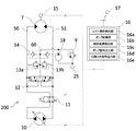
- FIG. 2 is a schematic configuration diagram of a hydraulic closed circuit system mounted on the hydraulic shovel 100. As shown in FIG. In addition, in FIG. 2, only the part in connection with the drive of the turning motor 7 is shown for the simplification of description, and the part in connection with the drive of the other hydraulic actuator is abbreviate
- the hydraulic closed circuit system 200 includes a dual tilt hydraulic pump (hereinafter referred to as a pump) 10 driven by an engine (not shown), a charge pump 18, a swing motor 7, and an upper swing body 102.
- a swing control lever 17 for instructing an operation, flow paths 50, 51 connecting the pump 10 and the swing motor 7 in an annular shape (closed circuit shape), and a switching valve 11 connecting or blocking the flow paths 50, 51
- the charge relief valve 9, the flushing valve 12, the relief valves 13a and 13b, the makeup valve 14, the speed sensor 15 as a swing speed detection device for detecting the rotation speed of the swing motor 7, and a control device And a controller 16.
- the discharge port of the charge pump 18 is connected to the charge flow path 60.
- the charge flow path 60 is connected to the hydraulic oil tank 25 via the charge relief valve 9.
- the charge relief valve 9 discharges the surplus oil of the charge flow passage 60 to the hydraulic oil tank 25 and maintains the pressure of the charge flow passage 60 at a certain level or less.
- the flow paths 50 and 51 are connected to the charge flow path 60 via the flushing valve 12, the relief valves 13 a and 13 b, and the make-up valve 14.
- the flushing valve 12 discharges the excess flow rate of the flow channels 50, 51 to the charge flow channel 60 by connecting the low pressure side of the flow channels 50, 51 to the charge flow channel 60, or the shortage of the flow channels 50, 51
- the flow rate is replenished from the charge flow path 60.
- the relief valves 13a and 13b discharge excess oil in the flow channels 50 and 51 to the charge flow channel 60 when the pressure in the flow channels 50 and 51 reaches a preset pressure, and the pressure in the flow channels 50 and 51 is below a certain level. Keep it
- the make-up valve 14 supplies hydraulic fluid of the charge flow passage 60 to the flow passages 50, 51 so that the flow passages 50, 51 do not become negative pressure.
- the controller 16 controls the pump 10 and the switching valve 11 based on the operation amount of the turning operation lever 17 and information from various sensors including the speed sensor 15.
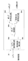
- FIG. 3 is a functional block diagram of the controller 16.
- the controller 16 includes a lever operation detection unit 16a, a pump control unit 16b, a turning speed detection unit 16c, a pump signal output unit 16d, and a switching valve signal output unit 16e.
- the lever operation detection unit 16a calculates the lever operation amount based on the operation signal from the turning operation lever 17, and outputs the amount to the pump control unit 16b.
- the swing speed detection unit 16 c calculates the swing speed of the upper swing body 102 based on the detection signal of the speed sensor 15 and outputs the calculated swing speed to the pump control unit 16 b.
- the pump control unit 16b generates a tilting angle command of the pump 10 and an opening / closing command of the switching valve 11 based on the lever operation amount from the lever operation detection unit 16a and the swing speed from the swing speed detection unit 16c. It outputs to the pump signal output part 16d and the switching valve signal output part 16e, respectively.
- the pump signal output unit 16 d controls the pump 10 in accordance with the tilt angle command from the pump control unit 16 b.
- the switching valve signal output unit 16e controls the switching 11 in accordance with the open / close command from the pump control unit 16b.
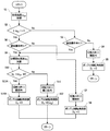
- FIG. 4 is a flowchart showing the process of the pump control unit 16b according to the present embodiment. Hereinafter, each step will be described in order.
- step S1 the turning speed ⁇ act is acquired from the turning speed detection unit 16c.
- the turning speed ⁇ act takes a positive value when turning right, and takes a negative value when turning left.
- step S2 it is determined in step S2 whether or not the upper swing body 102 is turning. Specifically, it is determined based on whether or not the absolute value of the turning speed ⁇ act is larger than zero.
- step S2 When it determines with No (during turning stop) by step S2, it is determined whether the turning operation lever 17 was operated by step S3.
- step S3 When it determines with No (swing operation absence) by step S3, the switching valve 11 is closed by step S4, the tilting angle DP of the pump 10 is controlled to 0 by step S5, and it returns to step S1. As a result, no hydraulic fluid is supplied from the pump 10 to the swing motor 7 and the swing motor 7 is kept in the stopped state.
- step S2 When it is determined as Yes (turning) in step S2, it is determined in step S6 whether the turning operation lever 17 is operated.
- step S6 When it determines with No (swing operation absence) by step S6, the switching valve 11 is closed by step S7, tilting angle DP of the pump 10 is controlled to 0 by step S8, and it returns to step S1. Thereby, the supply of the hydraulic fluid from the pump 10 to the swing motor 7 is stopped, and the swing motor 7 starts to decelerate.
- step S3 If it is determined in step S3 that the result is Yes (the turning operation is present), or if it is determined in step S6 that the result is Yes (the turning operation is present), the target turning speed ⁇ d is calculated based on the lever operation amount in step S9.
- the target turning speed ⁇ d takes a positive value when turning right, and takes a negative value when turning left, as with the turning speed ⁇ act.
- step S10 it is determined in step S10 whether or not a reverse lever operation to instruct turning in a direction opposite to the turning direction is performed. Specifically, the determination is made based on whether or not the product of the target turning speed ⁇ d and the turning speed ⁇ act is 0 or less. If the product of the target turning speed ⁇ d and the turning speed ⁇ act is less than or equal to 0, the turning direction corresponding to the turning speed ⁇ act is different from the turning direction corresponding to the lever operation amount, so reverse lever operation is performed (Yes It is determined that On the other hand, when the product of the target turning speed ⁇ d and the turning speed ⁇ act is larger than 0, the current turning direction matches the turning direction intended by the operator, and thus the forward lever operation is performed ( It is judged as No).
- step S10 When it is determined as No (forward lever operation) in step S10, the switching valve 11 is opened in step S11, the tilt angle DP of the pump 10 is controlled in step S12 according to the target swing speed ⁇ d, and the process returns to step S1. . As a result, hydraulic fluid is supplied from the pump 10 to the swing motor 7 and the swing motor 7 is driven.
- Step S10 When it is determined as Yes (reverse lever operation) in Step S10, the switching valve 11 is opened in Step S13, and in Step S14, the tilt angle DP of the pump 10 is a gain smaller than 1 at the target turning speed ⁇ d (this embodiment) Then, control is performed according to the product multiplied by 0.8), and the process returns to step S1.
- the reverse lever operation is being performed, the flow rate sucked into the pump 10 from the flow path 50 or 51 on the suction side of the swing motor 7 is suppressed lower than in the case where control is performed according to the target swing speed ⁇ d.
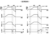
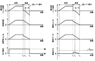
- FIG. 5 is a diagram showing an operation when a reverse lever operation is performed to instruct a swing in a direction opposite to the swing direction during swing decelerating in the hydraulic closed circuit system 200 to which the control according to the prior art is applied.
- the switching valve 11 opens to connect the swing motor 7 and the pump 10 in a closed circuit.
- the tilt angle of the pump 10 is increased to the discharge side of the swing motor 7 according to the amount of operation of the swing control lever 17.
- the switching valve 11 is opened in response to the operation of the turning operation lever 17 to connect the turning motor 7 and the pump 10 in a closed circuit.
- the hydraulic fluid is supplied from the pump 10 to the swing motor 7 through the flow path 50 or 51, so that the pump flow rate and the motor flow rate increase.
- the pump flow rate becomes 0, and the motor flow rate is also reduced because the supply of hydraulic fluid from the pump 10 is stopped.
- the pressure in the flow path 50 or 51 on the discharge side of the swing motor 7 is increased by closing the switching valve 11 in the flow paths 50 and 51 that connected the pump 10 and the swing motor 7 in a closed circuit.
- the hydraulic oil is discharged from the relief valve 13a or 13b to the charge flow passage 60.
- the pressure on the discharge side of the swing motor 7 increases to the set pressure of the relief valve 13a or 13b, whereby the swing motor 7 starts to decelerate.
- the suction flow rate of the swing motor 7 is supplied from the charge pump 18 via the makeup valve 14 or the flushing valve 12 (replenishing valve device).
- a reverse lever operation to start turning in a direction opposite to the turning direction is started.
- the pump 10 sucks the working oil from the flow path 50 or 51 on the suction side of the swing motor 7 and discharges the working oil to the flow path 51 or 50 on the discharge side of the swing motor 7 according to the reverse lever operation.
- the suction flow rate of the pump 10 is supplied from the charge pump 18 via the make-up valve 14 or the flushing valve 12 (replenishing valve device), as the suction flow rate of the swing motor 7.
- the total flow rate of the suction flow rate of the swing motor 7 and the suction flow rate of the pump 10 may temporarily exceed the flow rate (chargeable flow rate) QCHmax that can be supplied by the charge pump 18.
- a negative pressure is generated in the closed circuit (flow paths 50 and 51), and there is a risk that cavitation may occur.
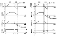
- FIG. 6 is a diagram showing an operation when the reverse lever operation is performed in the hydraulic closed circuit system 200 according to the present embodiment. The differences from the prior art (shown in FIG. 5) will be described below.
- the pump 10 discharges hydraulic fluid according to the lever operation amount, and the switching valve 11 opens to form a flow path.
- the pump displacement angle is controlled such that the discharge flow rate (pump flow rate) of the pump 10 becomes smaller than the pump flow rate corresponding to the target swing speed ⁇ d.
- the flow rate of the flow sucked into the pump 10 from the flow paths 50 and 51 corresponds to the pump flow rate Can be kept lower than.
- the insufficient flow rate in the closed circuit (flow passages 50, 51) becomes equal to or less than the flow rate (chargeable flow rate) QCHmax that can be covered by the charge pump 18, and thus the closed circuit (flow passages 50, 51) has a negative pressure. And the risk of cavitation can be reduced.
- FIGS. 7 and 8 A hydraulic excavator 100 according to a second embodiment of the present invention will be described using FIGS. 7 and 8.
- FIG. 7 is a flowchart showing the process of the pump control unit 16b (shown in FIG. 3) according to this embodiment.
- FIG. 7 differences from the first embodiment (shown in FIG. 4) will be mainly described.
- step S10 when it is determined as Yes (reverse lever operation) in step S10, the switching valve 11 is closed in step S13A, the tilting angle DP of the pump 10 is controlled to 0 in step S14A, and the process returns to step S1.
- the discharge flow rate (pump flow rate) of the pump 10 is zero.
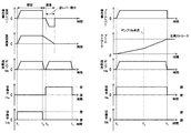
- FIG. 8 is a diagram showing an operation of the hydraulic closed circuit system 200 when the reverse lever operation is performed in the hydraulic shovel 100 according to the present embodiment.
- the difference from the first embodiment shown in FIG. 6 will be described.
- the flow rate sucked into the pump 10 from the flow path 50 or 51 on the suction side of the swing motor 7 is 0 It becomes.
- the shortage flow rate in the closed circuit (flow paths 50 and 51) becomes smaller than in the first embodiment (shown in FIG. 4), so the risk of cavitation generation is suppressed lower than in the first embodiment.
- FIGS. 9 and 10 A hydraulic shovel 100 according to a third embodiment of the present invention will be described using FIGS. 9 and 10.
- FIG. 9 is a flowchart showing processing of the pump control unit 16b (shown in FIG. 3) according to the present embodiment. Hereinafter, the difference from the first embodiment (shown in FIG. 4) will be described.
- step S6 determines No (no turning operation)
- the switching valve 11 is opened in step S7B, and in step S8B, the tilting angle DP of the pump 10 is a gain smaller than 1 at the turning speed ⁇ act ( In this embodiment, the product multiplied by 0.8) is controlled as the target turning speed, and the process returns to step S1.
- a part (80% in this embodiment) of the flow (motor flow) sucked into the turning motor 7 from the flow path 50 or 51 is supplied from the pump 10 Be done.
- step S14B the tilt angle DP of the pump 10 is controlled as the target swing speed by multiplying the swing speed ⁇ act by a gain smaller than 1 (0.8 in this embodiment), and the process returns to step S1. .
- a part (80% in this embodiment) of the flow (motor flow) sucked into the swing motor 7 from the flow path 50 or 51 is supplied from the pump 10.
- FIG. 10 is a diagram showing an operation of the hydraulic closed circuit system 200 when the reverse lever operation is performed in the hydraulic shovel 100 according to the present embodiment.
- the difference from the first embodiment shown in FIG. 6 will be described.
- a hydraulic excavator 100 according to a fourth embodiment of the present invention will be described with reference to FIGS. 11 to 13.
- FIG. 11 is a schematic configuration diagram of a hydraulic closed circuit system mounted on the hydraulic shovel 100 according to the present embodiment.
- the hydraulic closed circuit system 201 is configured to turn on both tilt type first and second hydraulic pumps (hereinafter, pumps) 10 a and 10 b and charge pumps 18 and 23 driven by an engine (not shown).
- a switching valve 19a that connects or shuts off in a closed circuit via the passages 52, 53, and a switching valve 11a that connects or shuts off the pump 10b and the boom cylinder 1 in a closed circuit via the flow passages 52, 53
- Respective functions of the flushing valve 20, the relief valves 21a and 21b, the makeup valve 22, the charge pump 23, and the charge relief valve 24 are the flushing valve 12, the relief valves 13a and 13b, and the makeup valve described in the first embodiment.
- the function is the same as that of the charge pump 18 and the charge relief valve 9, and thus the description thereof is omitted.
- the controller 16 controls the pumps 10a and 10b and the switching valves 11a, 11b, 19a and 19b based on the respective operation amounts of the turning operation lever 17 and the boom operation lever 26 and information from various sensors including the speed sensor 15. .
- the switching valves 19a and 11b are opened and the switching valves 19b and 11a are closed so that the pump 10a closes the boom cylinder 1
- the pump 10b is connected in a closed circuit to the swing motor 7, the tilt angle of the pump 10a is controlled according to the operation amount of the boom control lever 26, and the pump 10b is tilted according to the operation amount of the turn control lever 17. The corners are controlled.
- FIG. 12 is a flowchart showing the process of the pump control unit 16b according to the present embodiment. Hereinafter, each step will be described in order.
- Steps S101 to S103 and S106 are the same as steps S1 to S3 and S6 in the first embodiment (shown in FIG. 4), and thus the description thereof is omitted.
- step S103 When it determines with No (swing operation absence) by step S103, switching valve 19b, 11b is closed by step S104, tilting angle DP of pump 10a, 10b is controlled to 0 by step S105, and it returns to step S101. As a result, no hydraulic fluid is supplied from the pumps 10a and 10b to the swing motor 7, and the swing motor 7 is kept in the stopped state.
- step S106 If it is determined in step S106 that the result is No (no turning operation), it is determined in step S107 whether a boom operation has been performed.
- Step S107 When it is determined as No (no boom operation) in Step S107, the switching valve 19b or 11b is opened in Step S108, and the tilting angle DP of the pump 10a or 10b in Step S109 In this embodiment, the product multiplied by 0.8) is controlled as the target turning speed, and the process returns to step S101.
- the sole swing operation is performed and the swing operation is not performed, a part (80% in this embodiment) of the flow rate sucked into the swing motor 7 from the flow path 50 or 51 is supplied from the pump 10a or 10b. Be done.
- step S107 When it is determined as Yes (boom operation is performed) in step S107, the switching valve 19a or 11a is opened in step S110, the switching valves 19b and 11b are closed, and the pump 10a or 10b is switched according to the target boom speed VdBM in step S111.
- the tilt angle DP is controlled, and the process returns to step S101.
- hydraulic fluid is supplied from the pump 10a or 10b to the boom cylinder 1, and the boom cylinder 1 is driven.
- steps S112 and S113 are performed. Steps S112 and S113 are the same as steps S9 and S10 of the first embodiment (shown in FIG. 4), and thus the description thereof is omitted.
- Step S113 When it is determined as No (forward lever operation) in Step S113, the switching valve 19b or 11b is opened in Step S114, and the tilting angle DP of the pump 10a or 10b is controlled according to the target swing speed ⁇ d in Step S115. It returns to step S101. As a result, hydraulic fluid is supplied from the pump 10a or 10b to the swing motor 7, and the swing motor 7 is driven.
- step S113 When it is determined as Yes (reverse lever operation) in step S113, it is determined whether or not the boom operation has been performed in step S116.
- step S116 If it is determined No in step S116 (no boom operation), the reverse lever operation is performed during the swing single operation, so the switching valve 19b or 11b is opened in step S117, and the pump 10a or 10b is opened in step S118.
- the tilt angle is controlled by multiplying the turning speed ⁇ act by a gain smaller than 1 (0.8 in this embodiment) as the target turning speed, and the process returns to step S101.
- a part (80% in this embodiment) of the flow rate sucked into the swing motor 7 from the flow path 50 or 51 is from the pump 10a or 10b. Supplied.
- Step S116 When it is determined as Yes (boom operation is performed) in Step S116, the switching valves 19b and 11b are closed in Step S119, the switching valve 19a or 11a is opened according to the target boom speed VdBM, and the target boom speed VdBM is set in Step S120. Accordingly, the tilt angle DP of the pumps 10a and 10b is controlled, and the process returns to step S101. Thereby, when reverse lever operation is performed during boom operation, hydraulic fluid is supplied to boom cylinder 1 from pump 10a or 10b used for driving swing motor 7 according to target boom speed VdBM. .
- FIG. 13 is a diagram showing an operation of the hydraulic closed circuit system 200 when the reverse lever operation is performed in the hydraulic shovel 100 according to the present embodiment. In this embodiment, the case where the reverse lever operation is performed during combined operation of turning and boom raising will be described.
- the operation of the turning operation lever 17 and the boom operation lever 26 is started.
- the tilt angles of the pumps 10a and 10b are controlled according to the target speeds of the respective actuators 1 and 7, the switching valve 19a connecting the pump 10a and the boom cylinder 1 is opened, and the pump 10b and the swing motor 7 are The switching valve 11b to be connected opens.
- the boom cylinder 1 is driven according to the flow rate from the pump 10a
- the swing motor 7 is driven according to the flow rate from the pump 10b.
- the pump 10b connected to the swing motor 7 is connected to the boom cylinder 1, whereby the flow path 50 on the suction side of the swing motor 7
- the flow rate sucked into the pump 10a or 10b from 51 is zero, as in the second embodiment, the risk of cavitation can be suppressed.
- hydraulic fluid can be supplied to the boom cylinder 1 from the pump 10a or 10b used to drive the swing motor 7 during reverse lever operation, particularly in the hydraulic shovel 100 where combined operations of swing and boom raising are frequently used It becomes possible to improve work efficiency.
- Example of this invention was explained in full detail, this invention is not limited to an above-described Example, A various modified example is included.
- the embodiments described above are described in detail in order to explain the present invention in an easy-to-understand manner, and are not necessarily limited to those having all the configurations described.
- charge pump 19a , 19a ... switching valve, 20 ... flushing valve, 21a, 21b ... relief valve, 21b ... relief valve, 22 ... makeup valve 23: charge pump, 24: charge relief valve, 25: hydraulic oil tank, 26: boom control lever, 50 to 53: flow path, 60: charge flow path, 100: hydraulic excavator, 101: cab, 102: upper swing body , 103 ... lower traveling body, 104 ... front work machine, 200, 201 ... hydraulic closed circuit system.
Landscapes
- Engineering & Computer Science (AREA)
- General Engineering & Computer Science (AREA)
- Mining & Mineral Resources (AREA)
- Civil Engineering (AREA)
- Structural Engineering (AREA)
- Physics & Mathematics (AREA)
- Fluid Mechanics (AREA)
- Mechanical Engineering (AREA)
- Operation Control Of Excavators (AREA)
- Fluid-Pressure Circuits (AREA)
Priority Applications (2)
| Application Number | Priority Date | Filing Date | Title |
|---|---|---|---|
| US16/646,777 US10914053B2 (en) | 2017-12-28 | 2018-11-16 | Work machine |
| EP18895418.4A EP3667102B1 (en) | 2017-12-28 | 2018-11-16 | Work machine |
Applications Claiming Priority (2)
| Application Number | Priority Date | Filing Date | Title |
|---|---|---|---|
| JP2017253186A JP6975036B2 (ja) | 2017-12-28 | 2017-12-28 | 作業機械 |
| JP2017-253186 | 2017-12-28 |
Publications (1)
| Publication Number | Publication Date |
|---|---|
| WO2019130898A1 true WO2019130898A1 (ja) | 2019-07-04 |
Family
ID=67066959
Family Applications (1)
| Application Number | Title | Priority Date | Filing Date |
|---|---|---|---|
| PCT/JP2018/042514 Ceased WO2019130898A1 (ja) | 2017-12-28 | 2018-11-16 | 作業機械 |
Country Status (4)
| Country | Link |
|---|---|
| US (1) | US10914053B2 (enExample) |
| EP (1) | EP3667102B1 (enExample) |
| JP (1) | JP6975036B2 (enExample) |
| WO (1) | WO2019130898A1 (enExample) |
Families Citing this family (2)
| Publication number | Priority date | Publication date | Assignee | Title |
|---|---|---|---|---|
| JP7090567B2 (ja) * | 2019-01-25 | 2022-06-24 | 日立建機株式会社 | 建設機械 |
| JP2023151652A (ja) * | 2022-03-31 | 2023-10-16 | 住友建機株式会社 | ショベル |
Citations (5)
| Publication number | Priority date | Publication date | Assignee | Title |
|---|---|---|---|---|
| JP2014005679A (ja) * | 2012-06-26 | 2014-01-16 | Kobelco Contstruction Machinery Ltd | 旋回式作業機械 |
| JP2015075171A (ja) * | 2013-10-09 | 2015-04-20 | 日立住友重機械建機クレーン株式会社 | 建設機械の旋回制御装置 |
| JP2015074531A (ja) * | 2013-10-09 | 2015-04-20 | 日立住友重機械建機クレーン株式会社 | 建設機械の旋回制御装置 |
| WO2015198644A1 (ja) | 2014-06-26 | 2015-12-30 | 日立建機株式会社 | 作業機械 |
| JP2017106251A (ja) * | 2015-12-10 | 2017-06-15 | 日立建機株式会社 | 作業機械の駆動装置 |
Family Cites Families (4)
| Publication number | Priority date | Publication date | Assignee | Title |
|---|---|---|---|---|
| JP5333511B2 (ja) * | 2011-05-02 | 2013-11-06 | コベルコ建機株式会社 | 旋回式作業機械 |
| JP5738674B2 (ja) * | 2011-05-25 | 2015-06-24 | コベルコ建機株式会社 | 旋回式作業機械 |
| WO2015021400A1 (en) * | 2013-08-08 | 2015-02-12 | Parker-Hannifin Corporation | Hydraulic hybrid swing drive system for excavators |
| JP6335093B2 (ja) * | 2014-10-10 | 2018-05-30 | 川崎重工業株式会社 | 建設機械の油圧駆動システム |
-
2017
- 2017-12-28 JP JP2017253186A patent/JP6975036B2/ja not_active Expired - Fee Related
-
2018
- 2018-11-16 US US16/646,777 patent/US10914053B2/en active Active
- 2018-11-16 EP EP18895418.4A patent/EP3667102B1/en active Active
- 2018-11-16 WO PCT/JP2018/042514 patent/WO2019130898A1/ja not_active Ceased
Patent Citations (5)
| Publication number | Priority date | Publication date | Assignee | Title |
|---|---|---|---|---|
| JP2014005679A (ja) * | 2012-06-26 | 2014-01-16 | Kobelco Contstruction Machinery Ltd | 旋回式作業機械 |
| JP2015075171A (ja) * | 2013-10-09 | 2015-04-20 | 日立住友重機械建機クレーン株式会社 | 建設機械の旋回制御装置 |
| JP2015074531A (ja) * | 2013-10-09 | 2015-04-20 | 日立住友重機械建機クレーン株式会社 | 建設機械の旋回制御装置 |
| WO2015198644A1 (ja) | 2014-06-26 | 2015-12-30 | 日立建機株式会社 | 作業機械 |
| JP2017106251A (ja) * | 2015-12-10 | 2017-06-15 | 日立建機株式会社 | 作業機械の駆動装置 |
Also Published As
| Publication number | Publication date |
|---|---|
| US10914053B2 (en) | 2021-02-09 |
| US20200291612A1 (en) | 2020-09-17 |
| EP3667102B1 (en) | 2023-09-27 |
| JP6975036B2 (ja) | 2021-12-01 |
| EP3667102A4 (en) | 2021-05-12 |
| JP2019120262A (ja) | 2019-07-22 |
| EP3667102A1 (en) | 2020-06-17 |
Similar Documents
| Publication | Publication Date | Title |
|---|---|---|
| JP6106097B2 (ja) | 作業機械の動力回生装置および作業機械 | |
| JP6740132B2 (ja) | ショベル | |
| KR101834589B1 (ko) | 선회체를 갖는 건설 기계 | |
| JP5542016B2 (ja) | 作業機械の駆動制御方法 | |
| CN103562565B (zh) | 回转式工程机械 | |
| JP6244459B2 (ja) | 作業機械 | |
| WO2012081201A1 (ja) | 作業機械の駆動制御方法 | |
| WO2012033064A1 (ja) | 建設機械のハイブリッドシステム | |
| JP6915042B2 (ja) | ショベル | |
| CN112105785A (zh) | 工程机械的液压驱动装置 | |
| KR20190122868A (ko) | 건설기계 | |
| EP2952638B1 (en) | Hybrid construction machine with swingable superstructure | |
| JP6013503B2 (ja) | 建設機械 | |
| JP6814309B2 (ja) | 建設機械 | |
| WO2019130898A1 (ja) | 作業機械 | |
| JP5324981B2 (ja) | 作業機械 | |
| JP2008275100A (ja) | 建設車両 | |
| JP7397194B2 (ja) | 建設機械 | |
| JP7523290B2 (ja) | 液圧駆動システム | |
| CN114258462B (zh) | 工程机械 | |
| JP6696517B2 (ja) | 油圧ショベル | |
| JP5568509B2 (ja) | 油圧制御装置および作業機械 | |
| WO2021066029A1 (ja) | 建設機械 | |
| JP2006349092A (ja) | 作業機械のハイブリッドシステム | |
| JP7654920B2 (ja) | ショベル |
Legal Events
| Date | Code | Title | Description |
|---|---|---|---|
| 121 | Ep: the epo has been informed by wipo that ep was designated in this application |
Ref document number: 18895418 Country of ref document: EP Kind code of ref document: A1 |
|
| ENP | Entry into the national phase |
Ref document number: 2018895418 Country of ref document: EP Effective date: 20200313 |
|
| NENP | Non-entry into the national phase |
Ref country code: DE |