EP3667102B1 - Work machine - Google Patents
Work machine Download PDFInfo
- Publication number
- EP3667102B1 EP3667102B1 EP18895418.4A EP18895418A EP3667102B1 EP 3667102 B1 EP3667102 B1 EP 3667102B1 EP 18895418 A EP18895418 A EP 18895418A EP 3667102 B1 EP3667102 B1 EP 3667102B1
- Authority
- EP
- European Patent Office
- Prior art keywords
- swing
- pump
- hydraulic
- boom
- flow
- Prior art date
- Legal status (The legal status is an assumption and is not a legal conclusion. Google has not performed a legal analysis and makes no representation as to the accuracy of the status listed.)
- Active
Links
Images


Classifications
-
- E—FIXED CONSTRUCTIONS
- E02—HYDRAULIC ENGINEERING; FOUNDATIONS; SOIL SHIFTING
- E02F—DREDGING; SOIL-SHIFTING
- E02F9/00—Component parts of dredgers or soil-shifting machines, not restricted to one of the kinds covered by groups E02F3/00 - E02F7/00
- E02F9/20—Drives; Control devices
- E02F9/22—Hydraulic or pneumatic drives
- E02F9/2221—Control of flow rate; Load sensing arrangements
- E02F9/2232—Control of flow rate; Load sensing arrangements using one or more variable displacement pumps
- E02F9/2235—Control of flow rate; Load sensing arrangements using one or more variable displacement pumps including an electronic controller
-
- E—FIXED CONSTRUCTIONS
- E02—HYDRAULIC ENGINEERING; FOUNDATIONS; SOIL SHIFTING
- E02F—DREDGING; SOIL-SHIFTING
- E02F9/00—Component parts of dredgers or soil-shifting machines, not restricted to one of the kinds covered by groups E02F3/00 - E02F7/00
- E02F9/20—Drives; Control devices
- E02F9/22—Hydraulic or pneumatic drives
- E02F9/2278—Hydraulic circuits
- E02F9/2296—Systems with a variable displacement pump
-
- E—FIXED CONSTRUCTIONS
- E02—HYDRAULIC ENGINEERING; FOUNDATIONS; SOIL SHIFTING
- E02F—DREDGING; SOIL-SHIFTING
- E02F3/00—Dredgers; Soil-shifting machines
- E02F3/04—Dredgers; Soil-shifting machines mechanically-driven
- E02F3/28—Dredgers; Soil-shifting machines mechanically-driven with digging tools mounted on a dipper- or bucket-arm, i.e. there is either one arm or a pair of arms, e.g. dippers, buckets
- E02F3/36—Component parts
- E02F3/42—Drives for dippers, buckets, dipper-arms or bucket-arms
- E02F3/43—Control of dipper or bucket position; Control of sequence of drive operations
- E02F3/435—Control of dipper or bucket position; Control of sequence of drive operations for dipper-arms, backhoes or the like
-
- E—FIXED CONSTRUCTIONS
- E02—HYDRAULIC ENGINEERING; FOUNDATIONS; SOIL SHIFTING
- E02F—DREDGING; SOIL-SHIFTING
- E02F9/00—Component parts of dredgers or soil-shifting machines, not restricted to one of the kinds covered by groups E02F3/00 - E02F7/00
- E02F9/08—Superstructures; Supports for superstructures
- E02F9/10—Supports for movable superstructures mounted on travelling or walking gears or on other superstructures
- E02F9/12—Slewing or traversing gears
- E02F9/121—Turntables, i.e. structure rotatable about 360°
- E02F9/123—Drives or control devices specially adapted therefor
-
- E—FIXED CONSTRUCTIONS
- E02—HYDRAULIC ENGINEERING; FOUNDATIONS; SOIL SHIFTING
- E02F—DREDGING; SOIL-SHIFTING
- E02F9/00—Component parts of dredgers or soil-shifting machines, not restricted to one of the kinds covered by groups E02F3/00 - E02F7/00
- E02F9/20—Drives; Control devices
- E02F9/22—Hydraulic or pneumatic drives
- E02F9/2203—Arrangements for controlling the attitude of actuators, e.g. speed, floating function
-
- E—FIXED CONSTRUCTIONS
- E02—HYDRAULIC ENGINEERING; FOUNDATIONS; SOIL SHIFTING
- E02F—DREDGING; SOIL-SHIFTING
- E02F9/00—Component parts of dredgers or soil-shifting machines, not restricted to one of the kinds covered by groups E02F3/00 - E02F7/00
- E02F9/20—Drives; Control devices
- E02F9/22—Hydraulic or pneumatic drives
- E02F9/2221—Control of flow rate; Load sensing arrangements
- E02F9/2239—Control of flow rate; Load sensing arrangements using two or more pumps with cross-assistance
- E02F9/2242—Control of flow rate; Load sensing arrangements using two or more pumps with cross-assistance including an electronic controller
-
- E—FIXED CONSTRUCTIONS
- E02—HYDRAULIC ENGINEERING; FOUNDATIONS; SOIL SHIFTING
- E02F—DREDGING; SOIL-SHIFTING
- E02F9/00—Component parts of dredgers or soil-shifting machines, not restricted to one of the kinds covered by groups E02F3/00 - E02F7/00
- E02F9/20—Drives; Control devices
- E02F9/22—Hydraulic or pneumatic drives
- E02F9/226—Safety arrangements, e.g. hydraulic driven fans, preventing cavitation, leakage, overheating
-
- E—FIXED CONSTRUCTIONS
- E02—HYDRAULIC ENGINEERING; FOUNDATIONS; SOIL SHIFTING
- E02F—DREDGING; SOIL-SHIFTING
- E02F9/00—Component parts of dredgers or soil-shifting machines, not restricted to one of the kinds covered by groups E02F3/00 - E02F7/00
- E02F9/20—Drives; Control devices
- E02F9/22—Hydraulic or pneumatic drives
- E02F9/2278—Hydraulic circuits
- E02F9/2289—Closed circuit
-
- E—FIXED CONSTRUCTIONS
- E02—HYDRAULIC ENGINEERING; FOUNDATIONS; SOIL SHIFTING
- E02F—DREDGING; SOIL-SHIFTING
- E02F9/00—Component parts of dredgers or soil-shifting machines, not restricted to one of the kinds covered by groups E02F3/00 - E02F7/00
- E02F9/20—Drives; Control devices
- E02F9/22—Hydraulic or pneumatic drives
- E02F9/2278—Hydraulic circuits
- E02F9/2292—Systems with two or more pumps
-
- F—MECHANICAL ENGINEERING; LIGHTING; HEATING; WEAPONS; BLASTING
- F15—FLUID-PRESSURE ACTUATORS; HYDRAULICS OR PNEUMATICS IN GENERAL
- F15B—SYSTEMS ACTING BY MEANS OF FLUIDS IN GENERAL; FLUID-PRESSURE ACTUATORS, e.g. SERVOMOTORS; DETAILS OF FLUID-PRESSURE SYSTEMS, NOT OTHERWISE PROVIDED FOR
- F15B11/00—Servomotor systems without provision for follow-up action; Circuits therefor
- F15B11/02—Systems essentially incorporating special features for controlling the speed or actuating force of an output member
-
- F—MECHANICAL ENGINEERING; LIGHTING; HEATING; WEAPONS; BLASTING
- F15—FLUID-PRESSURE ACTUATORS; HYDRAULICS OR PNEUMATICS IN GENERAL
- F15B—SYSTEMS ACTING BY MEANS OF FLUIDS IN GENERAL; FLUID-PRESSURE ACTUATORS, e.g. SERVOMOTORS; DETAILS OF FLUID-PRESSURE SYSTEMS, NOT OTHERWISE PROVIDED FOR
- F15B11/00—Servomotor systems without provision for follow-up action; Circuits therefor
- F15B11/08—Servomotor systems without provision for follow-up action; Circuits therefor with only one servomotor
-
- F—MECHANICAL ENGINEERING; LIGHTING; HEATING; WEAPONS; BLASTING
- F15—FLUID-PRESSURE ACTUATORS; HYDRAULICS OR PNEUMATICS IN GENERAL
- F15B—SYSTEMS ACTING BY MEANS OF FLUIDS IN GENERAL; FLUID-PRESSURE ACTUATORS, e.g. SERVOMOTORS; DETAILS OF FLUID-PRESSURE SYSTEMS, NOT OTHERWISE PROVIDED FOR
- F15B2211/00—Circuits for servomotor systems
- F15B2211/20—Fluid pressure source, e.g. accumulator or variable axial piston pump
- F15B2211/205—Systems with pumps
- F15B2211/2053—Type of pump
- F15B2211/20546—Type of pump variable capacity
-
- F—MECHANICAL ENGINEERING; LIGHTING; HEATING; WEAPONS; BLASTING
- F15—FLUID-PRESSURE ACTUATORS; HYDRAULICS OR PNEUMATICS IN GENERAL
- F15B—SYSTEMS ACTING BY MEANS OF FLUIDS IN GENERAL; FLUID-PRESSURE ACTUATORS, e.g. SERVOMOTORS; DETAILS OF FLUID-PRESSURE SYSTEMS, NOT OTHERWISE PROVIDED FOR
- F15B2211/00—Circuits for servomotor systems
- F15B2211/20—Fluid pressure source, e.g. accumulator or variable axial piston pump
- F15B2211/205—Systems with pumps
- F15B2211/20576—Systems with pumps with multiple pumps
-
- F—MECHANICAL ENGINEERING; LIGHTING; HEATING; WEAPONS; BLASTING
- F15—FLUID-PRESSURE ACTUATORS; HYDRAULICS OR PNEUMATICS IN GENERAL
- F15B—SYSTEMS ACTING BY MEANS OF FLUIDS IN GENERAL; FLUID-PRESSURE ACTUATORS, e.g. SERVOMOTORS; DETAILS OF FLUID-PRESSURE SYSTEMS, NOT OTHERWISE PROVIDED FOR
- F15B2211/00—Circuits for servomotor systems
- F15B2211/60—Circuit components or control therefor
- F15B2211/63—Electronic controllers
- F15B2211/6303—Electronic controllers using input signals
- F15B2211/6346—Electronic controllers using input signals representing a state of input means, e.g. joystick position
-
- F—MECHANICAL ENGINEERING; LIGHTING; HEATING; WEAPONS; BLASTING
- F15—FLUID-PRESSURE ACTUATORS; HYDRAULICS OR PNEUMATICS IN GENERAL
- F15B—SYSTEMS ACTING BY MEANS OF FLUIDS IN GENERAL; FLUID-PRESSURE ACTUATORS, e.g. SERVOMOTORS; DETAILS OF FLUID-PRESSURE SYSTEMS, NOT OTHERWISE PROVIDED FOR
- F15B2211/00—Circuits for servomotor systems
- F15B2211/60—Circuit components or control therefor
- F15B2211/665—Methods of control using electronic components
- F15B2211/6654—Flow rate control
Definitions
- the present invention relates to a work machine such as a hydraulic excavator.
- Patent Document 1 describes a work machine including a first hydraulic circuit that connects a hydraulic motor (swing motor) as a first actuator for swing-driving a swing structure and a first pump motor (bidirectionally tiltable pump) to form a closed circuit in a flow line through which a hydraulic operating fluid flows and that is provided with a first opening/closing device that opens and closes a flow line between the hydraulic motor and the first pump motor, the first pump motor being able to cause the hydraulic operating fluid to flow in thereto and out therefrom in both directions and having a displacement volume that can be controlled, a second hydraulic circuit that connects a second hydraulic actuator different from the hydraulic motor and a second pump motor (bidirectionally tiltable pump) to form a closed circuit in a flow line through which a hydraulic operating fluid flows and that is provided with the second opening/closing device that opens and closes a flow line between the second hydraulic actuator and the second pump motor, the second pump motor being able to cause the hydraulic operating fluid to flow in thereto and out therefrom in both directions
- the controller includes a swing-deceleration sensing section that senses a state in which the swing structure is being decelerated, a pump operation determining section that determines an operation state of the second pump motor, and a control section that controls the displacement volumes of the first and second pump motors and opening and closing of the first and second opening/closing devices and the first-merging-flow-line opening/closing device.
- the pump operation determining section determines that the second pump motor is not supplying a hydraulic operating fluid to the second hydraulic actuator, and the first pump motor cannot singly regenerate the inertial energy that accompanies a swing
- the control section outputs an opening signal for the first opening/closing device, outputs a closing signal for the second opening/closing device, outputs an opening signal for the first-merging-flow-line opening/closing device that makes the second hydraulic closed circuit and the first hydraulic closed circuit merge, and furthermore controls the displacement volume of the first pump motor and the displacement volume of the second pump motor such that suction pressures thereof become higher than delivery pressures thereof to make the first pump motor and the second pump motor function as motors.
- the displacement volumes of the first and second pump motors are increased on a side where the suction pressures of the first and second pump motors become higher than their delivery pressures to make the first and second pump motor function as motors.
- Energy that is part of the energy of the hydraulic operating fluid discharged from a swing hydraulic motor while the swing structure is being decelerated and that cannot fully be regenerated singly by the first pump motor can thereby be regenerated by the second pump motor.
- Patent Document 1 WO2015/198644
- the suction-side of the swing motor is connected to the suction-side of the bidirectionally tiltable pump when reverse lever operation which is an instruction for a swing in a direction opposite to a swing direction is performed during swing deceleration. Accordingly, there is a fear that the pressure of the suction-side of the bidirectionally tiltable pump becomes a negative pressure and that cavitation occurs.
- US 2017/0306590 A1 discloses a work machine in accordance with the preamble of present claim 1, said work machine comprising a hydraulic system including a bidirectionally tiltable hydraulic pump and a controller controlling the tilting angle of the pump in accordance with an operation of the a swing operation lever.
- An object of the present invention is to provide a work machine that makes it possible, in a hydraulic closed-circuit system, to prevent occurrence of cavitation when reverse lever operation which is an instruction for a swing in a direction opposite to a swing direction is performed during swing deceleration.
- a work machine has the features of claim 1. It includes a lower track structure, an upper swing structure swingably attached onto the lower track structure, a swing motor that drives the upper swing structure, a bidirectionally tiltable first hydraulic pump, two flow lines that connect the swing motor and the first hydraulic pump to form a closed circuit, a charge pump, a charge flow line connected to the charge pump, a supplementing valve device that is provided between the two flow lines and the charge flow line and supplements a deficiency in a flow rate of the two flow lines with a flow from the charge flow line, a swing operation lever for giving an instruction on operation of the upper swing structure, a swing-velocity sensor that senses a swing velocity of the upper swing structure, and a controller that controls a tilting angle of the first hydraulic pump according to operation of the swing operation lever.
- the controller when a swing direction corresponding to a swing velocity sensed at the swing-velocity sensor is different from a swing direction corresponding to operation of the swing operation lever, the controller performs control such that a rate of a flow supplied from the first hydraulic pump to the swing motor becomes lower than a pump flow rate according to an operation amount of the swing operation lever.
- control when the swing direction corresponding to the swing velocity sensed at the swing-velocity sensor is different from the swing direction corresponding to the operation of the swing operation lever, control is performed such that the delivery flow rate of the first hydraulic pump becomes lower than the delivery flow rate according to the operation amount of the swing operation lever.
- reverse lever operation is performed during swing deceleration, the deficiency of the flow rate in the closed circuit is thereby kept at a rate of flow which can be supplied from the charge pump via the supplementing valve device or lower. Accordingly, occurrence of cavitation can be prevented.
- occurrence of cavitation can be prevented when reverse lever operation which is an instruction for a swing in a direction opposite to a swing direction is performed during swing deceleration.
- FIG. 1 is a side view illustrating a hydraulic excavator as one example of a work machine according to the present embodiment.
- a hydraulic excavator 100 includes a lower track structure 103 including crawler-type travel devices 8 on both sides in the left and right directions, and an upper swing structure 102 swingably attached onto the lower track structure 103.
- a cab 101 which an operator gets in is provided on the upper swing structure 102.
- the lower track structure 103 and the upper swing structure 102 can be swung via a swing motor 7 which is a hydraulic motor.
- a base end section of a front work implement 104 which is a work device for performing excavation work and the like, for example, is pivotably attached to the front side of the upper swing structure 102.
- the front side refers to the side which the operator who gets in the cab 101 faces (the left side in FIG. 1 ).
- the front work implement 104 includes a boom 2 whose base end section is coupled to the front side of the upper swing structure 102 such that the boom 2 can pivot upward and downward.
- the boom 2 is operated via a boom cylinder 1 which is a single rod type hydraulic cylinder.
- a base end section of an arm 4 is coupled to a tip end section of the boom 2 such that the arm 4 can pivot upward and downward and forward and backward.
- the arm 4 is operated via an arm cylinder 3 which is a single rod type hydraulic cylinder.
- a base end section of a bucket 6 is coupled to a tip end section of the arm 4 such that the bucket 6 can pivot upward and downward and forward and backward.
- the bucket 6 is operated via a bucket cylinder 5 which is a single rod type hydraulic cylinder.
- a boom-operation lever 26 (illustrated in FIG. 11 ), an arm operation lever (not illustrated), a bucket operation lever (not illustrated), and a swing operation lever 17 (illustrated in FIG. 2 ) for operating the boom 2, the arm 4, the bucket 6, and the upper swing structure 102 are arranged.
- the hydraulic excavator 100 according to a first embodiment of the present invention is explained by using FIG. 2 to FIG. 6 .
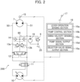
- FIG. 2 is a schematic configuration diagram of a hydraulic closed-circuit system mounted on the hydraulic excavator 100. Note that only sections related to driving of the swing motor 7 are illustrated in FIG. 2 for simplification of explanations, and sections related to driving of the other hydraulic actuators are omitted.
- a hydraulic closed-circuit system 200 includes a bidirectionally tiltable hydraulic pump (hereinafter, a pump) 10 and a charge pump 18 that are driven by an engine (not illustrated), the swing motor 7, the swing operation lever 17 for giving an instruction on operation of the upper swing structure 102, flow lines 50 and 51 that connect the pump 10 and the swing motor 7 annularly (to form a closed circuit), a selector valve 11 that establishes or interrupts communication through the flow lines 50 and 51, a charge relief valve 9, a flushing valve 12, relief valves 13a and 13b, a makeup valve 14, a velocity sensor 15 as a swing-velocity sensor that senses the rotation velocity of the swing motor 7, and a controller 16 as a controller.
- a pump bidirectionally tiltable hydraulic pump
- charge pump 18 for giving an instruction on operation of the upper swing structure 102
- flow lines 50 and 51 that connect the pump 10 and the swing motor 7 annularly (to form a closed circuit)
- a selector valve 11 that establishes or interrupts communication through the flow
- the delivery port of the charge pump 18 is connected to a charge flow line 60.
- the charge flow line 60 is connected to a hydraulic operating fluid tank 25 via the charge relief valve 9.
- the charge relief valve 9 discharges a surplus fluid in the charge flow line 60 to the hydraulic operating fluid tank 25 when the pressure in the charge flow line 60 becomes a preset pressure, and keeps the pressure in the charge flow line 60 at a certain pressure or lower.
- the flow lines 50 and 51 are connected to the charge flow line 60 via the flushing valve 12, the relief valves 13a and 13b, and the makeup valve 14.
- the flushing valve 12 connects the lower-pressure sides of the flow lines 50 and 51 to the charge flow line 60.
- surplus flow rate of the flow lines 50 and 51 is discharged to the charge flow line 60 or a deficiency of the flow rate of the flow lines 50 and 51 is supplemented with a flow from the charge flow line 60.
- the relief valves 13a and 13b discharge a surplus fluid in the flow lines 50 and 51 to the charge flow line 60 when the pressure in the flow lines 50 and 51 becomes a preset pressure, and keeps the pressure in the flow lines 50 and 51 at a certain pressure or lower.
- the makeup valve 14 supplies a hydraulic operating fluid in the charge flow line 60 to the flow lines 50 and 51 such that the pressure in the flow lines 50 and 51 does not becomes a negative pressure.
- the controller 16 controls the pump 10 and the selector valve 11 on the basis of an operation amount of the swing operation lever 17 and information from various types of sensors including the velocity sensor 15.
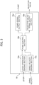
- FIG. 3 is a functional block diagram of the controller 16.
- the controller 16 includes a lever-operation sensing section 16a, a pump control section 16b, a swing-velocity sensing section 16c, a pump-signal output section 16d, and a selector-valve-signal output section 16e.
- the lever-operation sensing section 16a computes a lever operation amount on the basis of an operation signal from the swing operation lever 17, and outputs the computed lever operation amount to the pump control section 16b.
- the swing-velocity sensing section 16c calculates a swing velocity of the upper swing structure 102 on the basis of a sensing signal of the velocity sensor 15, and outputs the calculated swing velocity to the pump control section 16b.
- the pump control section 16b generates a tilting-angle command for the pump 10 and an opening/closing command for the selector valve 11 on the basis of the lever operation amount from the lever-operation sensing section 16a and the swing velocity from the swing-velocity sensing section 16c, and outputs the tilting-angle command and the opening/closing command to the pump-signal output section 16d and the selector-valve-signal output section 16e, respectively.
- the pump-signal output section 16d controls the pump 10 according to the tilting-angle command from the pump control section 16b.
- the selector-valve-signal output section 16e controls the switch 11 according to the opening/closing command from the pump control section 16b.
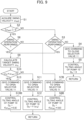
- FIG. 4 is a flowchart illustrating a process of the pump control section 16b according to the present embodiment. Hereinafter, steps are explained one by one.
- Step S1 a swing velocity ⁇ act is acquired from the swing-velocity sensing section 16c.
- the swing velocity ⁇ act assumes a positive value at the time of a rightward swing and a negative value at the time of a leftward swing.
- Step S2 it is determined whether or not the upper swing structure 102 is being swung. Specifically, the determination is made on the basis of whether or not the absolute value of the swing velocity ⁇ act is larger than 0.
- Step S3 it is determined whether or not the swing operation lever 17 is operated.
- Step S3 When the determination result in Step S3 is No (no swing operation performed), the selector valve 11 is closed in Step S4, a tilting angle DP of the pump 10 is controlled such that the tilting angle DP becomes 0 in Step S5, and the process returns to Step S1. A hydraulic operating fluid is thereby not supplied from the pump 10 to the swing motor 7, and the swing motor 7 is kept stopped.
- Step S6 it is determined whether or not the swing operation lever 17 is operated.
- Step S6 When the determination result in Step S6 is No (no swing operation performed), the selector valve 11 is closed in Step S7, the tilting angle DP of the pump 10 is controlled such that the tilting angle DP becomes 0 in Step S8, and the process returns to Step S1.
- the supply of the hydraulic operating fluid from the pump 10 to the swing motor 7 is thereby stopped, and deceleration of the swing motor 7 is started.
- Step S9 a target swing velocity ⁇ d is calculated on the basis of a lever operation amount.
- the target swing velocity ⁇ d assumes a positive value at the time of a rightward swing and a negative value at the time of a leftward swing.
- Step S10 it is determined whether or not reverse lever operation which is an instruction for a swing in a direction opposite to a swing direction is being performed. Specifically, the determination is made on the basis of whether or not the product of the target swing velocity ⁇ d by the swing velocity wact is equal to or smaller than 0.
- the product of the target swing velocity ⁇ d by the swing velocity wact is equal to or smaller than 0.
- the swing direction corresponding to the swing velocity wact is different from the swing direction corresponding to the lever operation amount. Accordingly, it is determined that reverse lever operation is being performed (Yes).
- the product of the target swing velocity ⁇ d by the swing velocity wact is larger than 0, the current swing direction is the same as the swing direction intended by an operator. Accordingly, it is determined that forward lever operation is being performed (No).
- Step S10 When the determination result in Step S10 is No (forward lever operation performed), the selector valve 11 is opened in Step S11, the tilting angle DP of the pump 10 is controlled according to the target swing velocity ⁇ d in Step S12, and the process returns to Step S1.
- the hydraulic operating fluid is thereby supplied from the pump 10 to the swing motor 7, and the swing motor 7 is driven.
- Step S10 When the determination result in Step S10 is Yes (reverse lever operation performed), the selector valve 11 is opened in Step S13, the tilting angle DP of the pump 10 is controlled according to the target swing velocity ⁇ d multiplied by a gain smaller than 1 (0.8 in the present embodiment) in Step S14, and the process returns to Step S1. While reverse lever operation is being performed, the rate of a flow to be taken in by the pump 10 from the flow line 50 or 51 on the suction-side of the swing motor 7 can thereby be kept lower than that in a case where the rate is controlled according to the target swing velocity wd.
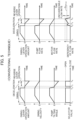
- FIG. 5 is a figure illustrating operation in the hydraulic closed-circuit system 200 to which control according to a conventional technology is applied, when reverse lever operation which is an instruction for a swing in a direction opposite to a swing direction is performed during swing deceleration.
- the hydraulic operating fluid is supplied from the pump 10 to the swing motor 7 via the flow line 50 or 51 by performing the operation of the swing operation lever 17 at Time T1. Accordingly, both the pump flow rate and the motor flow rate increase.
- the pump flow rate becomes 0, and the hydraulic operating fluid is no longer supplied from the pump 10.
- the the motor flow rate thus decreases as well.
- the communication through the flow lines 50 and 51 having been establishing a closed-circuit connection between the pump 10 and the swing motor 7 is interrupted by the selector valve 11.
- the pressure in the flow line 50 or 51 on the discharge-side of the swing motor 7 thereby increases, and the hydraulic operating fluid is discharged from the relief valve 13a or 13b to the charge flow line 60.
- the pressure on the discharge-side of the swing motor 7 increases to the pressure set for the relief valve 13a or 13b, and thus, deceleration of the swing motor 7 is started.
- the suction flow rate of the swing motor 7 is supplied from the charge pump 18 via the makeup valve 14 or the flushing valve 12 (supplementing valve device).
- the total flow rate of the suction flow rate of the swing motor 7 and the suction flow rate of the pump 10 temporarily exceeds the flow rate QCHmax that can be supplied by the charge pump 18 (chargeable flow rate), in some cases.
- the pressure in the closed circuit (flow lines 50 and 51) assumes a negative pressure, and the risk of occurrence of cavitation arises.
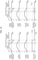
- FIG. 6 is a figure illustrating operation in the hydraulic closed-circuit system 200 according to the present embodiment when reverse lever operation is performed.
- FIG. 6 differences from the conventional technology (illustrated in FIG. 5 ) are explained.
- the pump 10 delivers the hydraulic operating fluid according to the lever operation amount, and the selector valve 11 is opened to form a flow line.
- the pump tilting angle is controlled such that the delivery flow rate of the pump 10 (pump flow rate) becomes lower than the pump flow rate according to the target swing velocity wd.
- the rate of the flow to be taken in by the pump 10 from the flow lines 50 and 51 can be kept lower than the pump flow rate according to the lever operation amount.
- the deficiency of the flow rate in the closed circuit (flow lines 50 and 51) thereby becomes equal to or lower than the flow rate QCHmax that can be supplied by the charge pump 18 (chargeable flow rate). Accordingly, the pressure in the closed circuit (flow lines 50 and 51) can be prevented from assuming a negative pressure, and the risk of occurrence of cavitation can be kept low.
- the hydraulic excavator 100 according to a second embodiment of the present invention is explained by using FIG. 7 and FIG. 8 .
- FIG. 7 is a flowchart illustrating a process of the pump control section 16b (illustrated in FIG. 3 ) according to the present embodiment.
- FIG. 7 differences from the first embodiment (illustrated in FIG. 4 ) are mainly explained.
- Step S10 when the determination result in Step S10 is Yes (reverse lever operation performed), the selector valve 11 is closed in Step S13A, the tilting angle DP of the pump 10 is controlled such that the tilting angle DP becomes 0 in Step S14A, and the process returns to Step S1.
- the delivery flow rate of pump 10 (pump flow rate) thereby becomes 0 while the reverse lever operation is being performed.
- FIG. 8 is a figure illustrating operation of the hydraulic closed-circuit system 200 when reverse lever operation is performed in the hydraulic excavator 100 according to the present embodiment.
- FIG. 8 differences from the first embodiment (illustrated in FIG. 6 ) are explained.
- the rate of the flow to be taken in by the pump 10 from the flow line 50 or 51 on the suction-side of the swing motor 7 becomes 0.
- the deficiency of the flow rate in the closed circuit (flow lines 50 and 51) thereby becomes smaller than that in the first embodiment (illustrated in FIG. 4 ). Accordingly, the risk of occurrence of cavitation can be kept lower than that in the first embodiment.
- the hydraulic excavator 100 according to a third embodiment of the present invention is explained by using FIG. 9 and FIG. 10 .
- FIG. 9 is a flowchart illustrating a process of the pump control section 16b (illustrated in FIG. 3 ) according to the present embodiment.
- FIG. 9 differences from the first embodiment (illustrated in FIG. 4 ) are explained.
- Step S6 when the determination result in Step S6 is No (no swing operation performed), the selector valve 11 is opened in Step S7B, the tilting angle DP of the pump 10 is controlled in Step S8B with the target swing velocity being set to the swing velocity wact multiplied by a gain smaller than 1 (0.8 in the present embodiment), and the process returns to Step S1. While a swing is being performed and swing operation is not being performed, part (80% in the present embodiment) of the rate of the flow to be taken in by the swing motor 7 from the flow line 50 or 51 (motor flow rate) is thereby supplied from the pump 10.
- Step S14B the tilting angle DP of the pump 10 is controlled with the target swing velocity being set to the swing velocity wact multiplied by a gain smaller than 1 (0.8 in the present embodiment), and the process returns to Step S1. While reverse lever operation is being performed, part (80% in the present embodiment) of the rate of the flow to be taken in by the swing motor 7 from the flow line 50 or 51 (motor flow rate) is thereby supplied from the pump 10.
- FIG. 10 is a figure illustrating operation of the hydraulic closed-circuit system 200 when reverse lever operation is performed in the hydraulic excavator 100 according to the present embodiment.
- FIG. 10 differences from the first embodiment (illustrated in FIG. 6 ) are explained.
- part (80% in the present embodiment) of the discharge flow rate of the swing motor 7 is taken in by the pump 10, and the remaining part (20% in the present embodiment) is discharged to the charge flow line 60 via the relief valve 13a or 13b. Accordingly, the braking force of the swing motor 7 is maintained.
- the hydraulic excavator 100 according to a fourth embodiment of the present invention is explained by using FIG. 11 to FIG. 13 .
- FIG. 11 is a schematic configuration diagram of a hydraulic closed-circuit system mounted on the hydraulic excavator 100 according to the present embodiment.
- a hydraulic closed-circuit system 201 includes bidirectionally tiltable first and second hydraulic pumps (hereinafter, pumps) 10a and 10b and charge pumps 18 and 23 that are driven by an engine (not illustrated), the swing motor 7, the boom cylinder 1, the swing operation lever 17 for giving an instruction on operation of the upper swing structure 102, the boom-operation lever 26 for giving an instruction on operation of the boom 2 a selector valve 19a that establishes or interrupts communication between the pump 10a and the boom cylinder 1 via flow lines 52 and 53 to form a closed circuit, a selector valve 11a that establishes or interrupts communication between the pump 10b and the boom cylinder 1 via the flow lines 52 and 53 to form a closed circuit a selector valve 19b that establishes or interrupts communication between the pump 10a and the swing motor 7 via the flow lines 50 and 51 to form a closed circuit, a selector valve 11b that establishes or interrupts communication between the pump 10b and the swing motor 7 via the flow lines 50 and 51 to form a closed circuit, a selector valve
- the functions of the flushing valve 20, the relief valves 21a and 21b, the makeup valve 22, the charge pump 23, and the charge relief valve 24 are similar to the functions of the flushing valve 12, the relief valves 13a and 13b, the makeup valve 14, the charge pump 18, and the charge relief valve 9 explained in the first embodiment. Accordingly, explanations thereof are omitted.
- the controller 16 controls the pumps 10a and 10b and the selector valves 11a, 11b, 19a, and 19b on the basis of operation amounts of the swing operation lever 17 and the boom-operation lever 26 and information from various types of sensors including the velocity sensor 15.
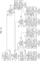
- FIG. 12 is a flowchart illustrating a process of the pump control section 16b according to the present embodiment. Hereinafter, steps are explained one by one.
- Steps S101 to S103 and S106 are similar to Steps S1 to S3 and S6 in the first embodiment (illustrated in FIG. 4 ). Accordingly, explanations thereof are omitted.
- Step S103 When the determination result in Step S103 is No (no swing operation performed), the selector valves 19b and 11b are closed in Step S104, the tilting angle DP of the pumps 10a and 10b are controlled such that the tilting angle DP becomes 0 in Step S105, and the process returns to Step S101. A hydraulic operating fluid is thereby not supplied from the pumps 10a and 10b to the swing motor 7, and the swing motor 7 is kept stopped.
- Step S107 it is determined whether or not boom operation is performed.
- Step S107 When the determination result in Step S107 is No (no boom operation performed), the selector valve 19b or 11b is opened in Step S108, the tilting angle DP of the pump 10a or 10b is controlled at Step S109 with the target swing velocity being set to the swing velocity wact multiplied by a gain smaller than 1 (0.8 in the present embodiment), and the process returns to Step S101. While a swing is being performed singly and swing operation is not being performed, part (80% in the present embodiment) of the rate of the flow to be taken in by the swing motor 7 from the flow line 50 or 51 is thereby supplied from the pump 10a or 10b.
- Step S107 When the determination result in Step S107 is Yes (boom operation performed), the selector valve 19a or 11a is opened and the selector valves 19b and 11b are closed in Step S110, the tilting angle DP of the pump 10a or 10b is controlled according to the target boom velocity VdBM in Step Sill, and the process returns to Step S101.
- the hydraulic operating fluid is thereby supplied from the pump 10a or 10b to the boom cylinder 1, and the boom cylinder 1 is driven.
- Steps S112 and S113 are executed. Steps S112 and S113 are similar to Steps S9 and S10 in the first embodiment (illustrated in FIG. 4 ). Accordingly, explanations thereof are omitted.
- Step S113 When the determination result in Step S113 is No (forward lever operation performed), the selector valve 19b or 11b is opened in Step S114, the tilting angle DP of the pump 10a or 10b is controlled according to the target swing velocity ⁇ d in Step S115, and the process returns to Step S101.
- the hydraulic operating fluid is thereby supplied from the pump 10a or 10b to the swing motor 7, and the swing motor 7 is driven.
- Step S116 it is determined whether or not boom operation is performed.
- Step S116 When the determination result in Step S116 is No (no boom operation performed), reverse lever operation is being performed while a swing is being performed singly. Accordingly, the selector valve 19b or 11b is opened in Step S117, the tilting angle of the pump 10a or 10b is controlled in Step S118 with the target swing velocity being set to the swing velocity wact multiplied by a gain smaller than 1 (0.8 in the present embodiment), and the process returns to Step S101. While a swing is being performed singly and reverse lever operation is being performed, part (80% in the present embodiment) of the rate of the flow to be taken in by the swing motor 7 from the flow line 50 or 51 is thereby supplied from the pump 10a or 10b.
- Step S116 When the determination result in Step S116 is Yes (boom operation performed), the selector valves 19b and 11b are closed and the selector valve 19a or 11a is opened according to the target boom velocity VdBM in Step S119, the tilting angles DP of the pumps 10a and 10b are controlled according to the target boom velocity VdBM at Step S120, and the process returns to Step S101.
- the hydraulic operating fluid is supplied to the boom cylinder 1 from the pump 10a or 10b which has been used for driving of the swing motor 7.
- FIG. 13 is a figure illustrating operation of the hydraulic closed-circuit system 200 when reverse lever operation is performed in the hydraulic excavator 100 according to the present embodiment.
- reverse lever operation is performed during combined operation of a swing and boom raising.
- the hydraulic pump having been connected to the swing motor is connected to the boom cylinder in a case that reverse lever operation is performed during combined operation of operation of the boom and a swing
- the section to which the hydraulic pump is connected may be a hydraulic cylinder other than the boom cylinder
- the hydraulic pump having been connected to the swing motor may be connected to a cylinder to drive an actuator other than the boom such as the arm or the bucket during combined operation of a swing and operation of the actuator other than the boom mentioned above.
Landscapes
- Engineering & Computer Science (AREA)
- General Engineering & Computer Science (AREA)
- Mining & Mineral Resources (AREA)
- Civil Engineering (AREA)
- Structural Engineering (AREA)
- Physics & Mathematics (AREA)
- Fluid Mechanics (AREA)
- Mechanical Engineering (AREA)
- Operation Control Of Excavators (AREA)
- Fluid-Pressure Circuits (AREA)
Applications Claiming Priority (2)
| Application Number | Priority Date | Filing Date | Title |
|---|---|---|---|
| JP2017253186A JP6975036B2 (ja) | 2017-12-28 | 2017-12-28 | 作業機械 |
| PCT/JP2018/042514 WO2019130898A1 (ja) | 2017-12-28 | 2018-11-16 | 作業機械 |
Publications (3)
| Publication Number | Publication Date |
|---|---|
| EP3667102A1 EP3667102A1 (en) | 2020-06-17 |
| EP3667102A4 EP3667102A4 (en) | 2021-05-12 |
| EP3667102B1 true EP3667102B1 (en) | 2023-09-27 |
Family
ID=67066959
Family Applications (1)
| Application Number | Title | Priority Date | Filing Date |
|---|---|---|---|
| EP18895418.4A Active EP3667102B1 (en) | 2017-12-28 | 2018-11-16 | Work machine |
Country Status (4)
| Country | Link |
|---|---|
| US (1) | US10914053B2 (enExample) |
| EP (1) | EP3667102B1 (enExample) |
| JP (1) | JP6975036B2 (enExample) |
| WO (1) | WO2019130898A1 (enExample) |
Families Citing this family (2)
| Publication number | Priority date | Publication date | Assignee | Title |
|---|---|---|---|---|
| JP7090567B2 (ja) * | 2019-01-25 | 2022-06-24 | 日立建機株式会社 | 建設機械 |
| JP2023151652A (ja) * | 2022-03-31 | 2023-10-16 | 住友建機株式会社 | ショベル |
Family Cites Families (9)
| Publication number | Priority date | Publication date | Assignee | Title |
|---|---|---|---|---|
| JP5333511B2 (ja) * | 2011-05-02 | 2013-11-06 | コベルコ建機株式会社 | 旋回式作業機械 |
| JP5738674B2 (ja) * | 2011-05-25 | 2015-06-24 | コベルコ建機株式会社 | 旋回式作業機械 |
| JP5590074B2 (ja) * | 2012-06-26 | 2014-09-17 | コベルコ建機株式会社 | 旋回式作業機械 |
| WO2015021400A1 (en) * | 2013-08-08 | 2015-02-12 | Parker-Hannifin Corporation | Hydraulic hybrid swing drive system for excavators |
| JP6095547B2 (ja) * | 2013-10-09 | 2017-03-15 | 日立住友重機械建機クレーン株式会社 | 建設機械の旋回制御装置 |
| JP6118705B2 (ja) * | 2013-10-09 | 2017-04-19 | 日立住友重機械建機クレーン株式会社 | 建設機械の旋回制御装置 |
| US10378185B2 (en) * | 2014-06-26 | 2019-08-13 | Hitachi Construction Machinery Co., Ltd. | Work machine |
| JP6335093B2 (ja) * | 2014-10-10 | 2018-05-30 | 川崎重工業株式会社 | 建設機械の油圧駆動システム |
| JP6605316B2 (ja) * | 2015-12-10 | 2019-11-13 | 日立建機株式会社 | 作業機械の駆動装置 |
-
2017
- 2017-12-28 JP JP2017253186A patent/JP6975036B2/ja not_active Expired - Fee Related
-
2018
- 2018-11-16 US US16/646,777 patent/US10914053B2/en active Active
- 2018-11-16 EP EP18895418.4A patent/EP3667102B1/en active Active
- 2018-11-16 WO PCT/JP2018/042514 patent/WO2019130898A1/ja not_active Ceased
Also Published As
| Publication number | Publication date |
|---|---|
| US10914053B2 (en) | 2021-02-09 |
| US20200291612A1 (en) | 2020-09-17 |
| WO2019130898A1 (ja) | 2019-07-04 |
| JP6975036B2 (ja) | 2021-12-01 |
| EP3667102A4 (en) | 2021-05-12 |
| JP2019120262A (ja) | 2019-07-22 |
| EP3667102A1 (en) | 2020-06-17 |
Similar Documents
| Publication | Publication Date | Title |
|---|---|---|
| US10995475B2 (en) | Construction machine | |
| CN107614896B (zh) | 挖土机及挖土机的驱动方法 | |
| CN105637229B (zh) | 油压挖掘机驱动系统 | |
| KR101952819B1 (ko) | 작업 기계의 유압 시스템 | |
| CN102459770B (zh) | 工程机械及工程机械的控制方法 | |
| EP3795843B1 (en) | Construction machine | |
| US9903393B2 (en) | Construction machine | |
| CN107532628A (zh) | 建筑机械的油压驱动系统 | |
| KR101747519B1 (ko) | 하이브리드식 건설 기계 | |
| EP3667102B1 (en) | Work machine | |
| JP6814309B2 (ja) | 建設機械 | |
| CN107882789B (zh) | 具有负流量控制的电液系统 | |
| KR101790903B1 (ko) | 건설 기계 | |
| JP6683641B2 (ja) | 油圧ショベル | |
| JP2011226491A (ja) | 油圧ショベルの旋回油圧回路 | |
| CN114258462B (zh) | 工程机械 | |
| CN116097008A (zh) | 液压驱动系统 | |
| CN111344459B (zh) | 工程机械的驱动系统 | |
| EP3940152B1 (en) | Work machine | |
| JP2006206205A (ja) | リフティングマグネットを備えた作業機械の油圧制御回路 | |
| EP3951092B1 (en) | Excavator | |
| KR102782892B1 (ko) | 작업 기계 | |
| JP7146669B2 (ja) | 建設機械 |
Legal Events
| Date | Code | Title | Description |
|---|---|---|---|
| STAA | Information on the status of an ep patent application or granted ep patent |
Free format text: STATUS: THE INTERNATIONAL PUBLICATION HAS BEEN MADE |
|
| PUAI | Public reference made under article 153(3) epc to a published international application that has entered the european phase |
Free format text: ORIGINAL CODE: 0009012 |
|
| STAA | Information on the status of an ep patent application or granted ep patent |
Free format text: STATUS: REQUEST FOR EXAMINATION WAS MADE |
|
| 17P | Request for examination filed |
Effective date: 20200313 |
|
| AK | Designated contracting states |
Kind code of ref document: A1 Designated state(s): AL AT BE BG CH CY CZ DE DK EE ES FI FR GB GR HR HU IE IS IT LI LT LU LV MC MK MT NL NO PL PT RO RS SE SI SK SM TR |
|
| AX | Request for extension of the european patent |
Extension state: BA ME |
|
| DAV | Request for validation of the european patent (deleted) | ||
| DAX | Request for extension of the european patent (deleted) | ||
| A4 | Supplementary search report drawn up and despatched |
Effective date: 20210413 |
|
| RIC1 | Information provided on ipc code assigned before grant |
Ipc: F15B 11/02 20060101AFI20210407BHEP Ipc: E02F 9/22 20060101ALI20210407BHEP Ipc: F15B 11/08 20060101ALI20210407BHEP Ipc: E02F 3/43 20060101ALI20210407BHEP Ipc: E02F 9/12 20060101ALI20210407BHEP |
|
| GRAP | Despatch of communication of intention to grant a patent |
Free format text: ORIGINAL CODE: EPIDOSNIGR1 |
|
| STAA | Information on the status of an ep patent application or granted ep patent |
Free format text: STATUS: GRANT OF PATENT IS INTENDED |
|
| INTG | Intention to grant announced |
Effective date: 20230509 |
|
| GRAS | Grant fee paid |
Free format text: ORIGINAL CODE: EPIDOSNIGR3 |
|
| GRAA | (expected) grant |
Free format text: ORIGINAL CODE: 0009210 |
|
| STAA | Information on the status of an ep patent application or granted ep patent |
Free format text: STATUS: THE PATENT HAS BEEN GRANTED |
|
| AK | Designated contracting states |
Kind code of ref document: B1 Designated state(s): AL AT BE BG CH CY CZ DE DK EE ES FI FR GB GR HR HU IE IS IT LI LT LU LV MC MK MT NL NO PL PT RO RS SE SI SK SM TR |
|
| REG | Reference to a national code |
Ref country code: GB Ref legal event code: FG4D |
|
| REG | Reference to a national code |
Ref country code: CH Ref legal event code: EP |
|
| REG | Reference to a national code |
Ref country code: DE Ref legal event code: R096 Ref document number: 602018058458 Country of ref document: DE |
|
| REG | Reference to a national code |
Ref country code: IE Ref legal event code: FG4D |
|
| REG | Reference to a national code |
Ref country code: LT Ref legal event code: MG9D |
|
| PG25 | Lapsed in a contracting state [announced via postgrant information from national office to epo] |
Ref country code: GR Free format text: LAPSE BECAUSE OF FAILURE TO SUBMIT A TRANSLATION OF THE DESCRIPTION OR TO PAY THE FEE WITHIN THE PRESCRIBED TIME-LIMIT Effective date: 20231228 |
|
| PG25 | Lapsed in a contracting state [announced via postgrant information from national office to epo] |
Ref country code: SE Free format text: LAPSE BECAUSE OF FAILURE TO SUBMIT A TRANSLATION OF THE DESCRIPTION OR TO PAY THE FEE WITHIN THE PRESCRIBED TIME-LIMIT Effective date: 20230927 Ref country code: RS Free format text: LAPSE BECAUSE OF FAILURE TO SUBMIT A TRANSLATION OF THE DESCRIPTION OR TO PAY THE FEE WITHIN THE PRESCRIBED TIME-LIMIT Effective date: 20230927 Ref country code: NO Free format text: LAPSE BECAUSE OF FAILURE TO SUBMIT A TRANSLATION OF THE DESCRIPTION OR TO PAY THE FEE WITHIN THE PRESCRIBED TIME-LIMIT Effective date: 20231227 Ref country code: LV Free format text: LAPSE BECAUSE OF FAILURE TO SUBMIT A TRANSLATION OF THE DESCRIPTION OR TO PAY THE FEE WITHIN THE PRESCRIBED TIME-LIMIT Effective date: 20230927 Ref country code: LT Free format text: LAPSE BECAUSE OF FAILURE TO SUBMIT A TRANSLATION OF THE DESCRIPTION OR TO PAY THE FEE WITHIN THE PRESCRIBED TIME-LIMIT Effective date: 20230927 Ref country code: HR Free format text: LAPSE BECAUSE OF FAILURE TO SUBMIT A TRANSLATION OF THE DESCRIPTION OR TO PAY THE FEE WITHIN THE PRESCRIBED TIME-LIMIT Effective date: 20230927 Ref country code: GR Free format text: LAPSE BECAUSE OF FAILURE TO SUBMIT A TRANSLATION OF THE DESCRIPTION OR TO PAY THE FEE WITHIN THE PRESCRIBED TIME-LIMIT Effective date: 20231228 Ref country code: FI Free format text: LAPSE BECAUSE OF FAILURE TO SUBMIT A TRANSLATION OF THE DESCRIPTION OR TO PAY THE FEE WITHIN THE PRESCRIBED TIME-LIMIT Effective date: 20230927 |
|
| REG | Reference to a national code |
Ref country code: NL Ref legal event code: MP Effective date: 20230927 |
|
| REG | Reference to a national code |
Ref country code: AT Ref legal event code: MK05 Ref document number: 1615674 Country of ref document: AT Kind code of ref document: T Effective date: 20230927 |
|
| PG25 | Lapsed in a contracting state [announced via postgrant information from national office to epo] |
Ref country code: NL Free format text: LAPSE BECAUSE OF FAILURE TO SUBMIT A TRANSLATION OF THE DESCRIPTION OR TO PAY THE FEE WITHIN THE PRESCRIBED TIME-LIMIT Effective date: 20230927 |
|
| PG25 | Lapsed in a contracting state [announced via postgrant information from national office to epo] |
Ref country code: IS Free format text: LAPSE BECAUSE OF FAILURE TO SUBMIT A TRANSLATION OF THE DESCRIPTION OR TO PAY THE FEE WITHIN THE PRESCRIBED TIME-LIMIT Effective date: 20240127 |
|
| PG25 | Lapsed in a contracting state [announced via postgrant information from national office to epo] |
Ref country code: AT Free format text: LAPSE BECAUSE OF FAILURE TO SUBMIT A TRANSLATION OF THE DESCRIPTION OR TO PAY THE FEE WITHIN THE PRESCRIBED TIME-LIMIT Effective date: 20230927 |
|
| PG25 | Lapsed in a contracting state [announced via postgrant information from national office to epo] |
Ref country code: ES Free format text: LAPSE BECAUSE OF FAILURE TO SUBMIT A TRANSLATION OF THE DESCRIPTION OR TO PAY THE FEE WITHIN THE PRESCRIBED TIME-LIMIT Effective date: 20230927 |
|
| PG25 | Lapsed in a contracting state [announced via postgrant information from national office to epo] |
Ref country code: SM Free format text: LAPSE BECAUSE OF FAILURE TO SUBMIT A TRANSLATION OF THE DESCRIPTION OR TO PAY THE FEE WITHIN THE PRESCRIBED TIME-LIMIT Effective date: 20230927 Ref country code: RO Free format text: LAPSE BECAUSE OF FAILURE TO SUBMIT A TRANSLATION OF THE DESCRIPTION OR TO PAY THE FEE WITHIN THE PRESCRIBED TIME-LIMIT Effective date: 20230927 Ref country code: IS Free format text: LAPSE BECAUSE OF FAILURE TO SUBMIT A TRANSLATION OF THE DESCRIPTION OR TO PAY THE FEE WITHIN THE PRESCRIBED TIME-LIMIT Effective date: 20240127 Ref country code: ES Free format text: LAPSE BECAUSE OF FAILURE TO SUBMIT A TRANSLATION OF THE DESCRIPTION OR TO PAY THE FEE WITHIN THE PRESCRIBED TIME-LIMIT Effective date: 20230927 Ref country code: EE Free format text: LAPSE BECAUSE OF FAILURE TO SUBMIT A TRANSLATION OF THE DESCRIPTION OR TO PAY THE FEE WITHIN THE PRESCRIBED TIME-LIMIT Effective date: 20230927 Ref country code: CZ Free format text: LAPSE BECAUSE OF FAILURE TO SUBMIT A TRANSLATION OF THE DESCRIPTION OR TO PAY THE FEE WITHIN THE PRESCRIBED TIME-LIMIT Effective date: 20230927 Ref country code: AT Free format text: LAPSE BECAUSE OF FAILURE TO SUBMIT A TRANSLATION OF THE DESCRIPTION OR TO PAY THE FEE WITHIN THE PRESCRIBED TIME-LIMIT Effective date: 20230927 Ref country code: SK Free format text: LAPSE BECAUSE OF FAILURE TO SUBMIT A TRANSLATION OF THE DESCRIPTION OR TO PAY THE FEE WITHIN THE PRESCRIBED TIME-LIMIT Effective date: 20230927 Ref country code: PT Free format text: LAPSE BECAUSE OF FAILURE TO SUBMIT A TRANSLATION OF THE DESCRIPTION OR TO PAY THE FEE WITHIN THE PRESCRIBED TIME-LIMIT Effective date: 20240129 |
|
| PG25 | Lapsed in a contracting state [announced via postgrant information from national office to epo] |
Ref country code: PL Free format text: LAPSE BECAUSE OF FAILURE TO SUBMIT A TRANSLATION OF THE DESCRIPTION OR TO PAY THE FEE WITHIN THE PRESCRIBED TIME-LIMIT Effective date: 20230927 Ref country code: IT Free format text: LAPSE BECAUSE OF FAILURE TO SUBMIT A TRANSLATION OF THE DESCRIPTION OR TO PAY THE FEE WITHIN THE PRESCRIBED TIME-LIMIT Effective date: 20230927 |
|
| REG | Reference to a national code |
Ref country code: DE Ref legal event code: R097 Ref document number: 602018058458 Country of ref document: DE Ref country code: CH Ref legal event code: PL |
|
| PG25 | Lapsed in a contracting state [announced via postgrant information from national office to epo] |
Ref country code: MC Free format text: LAPSE BECAUSE OF FAILURE TO SUBMIT A TRANSLATION OF THE DESCRIPTION OR TO PAY THE FEE WITHIN THE PRESCRIBED TIME-LIMIT Effective date: 20230927 |
|
| PG25 | Lapsed in a contracting state [announced via postgrant information from national office to epo] |
Ref country code: DK Free format text: LAPSE BECAUSE OF FAILURE TO SUBMIT A TRANSLATION OF THE DESCRIPTION OR TO PAY THE FEE WITHIN THE PRESCRIBED TIME-LIMIT Effective date: 20230927 |
|
| PG25 | Lapsed in a contracting state [announced via postgrant information from national office to epo] |
Ref country code: LU Free format text: LAPSE BECAUSE OF NON-PAYMENT OF DUE FEES Effective date: 20231116 |
|
| PG25 | Lapsed in a contracting state [announced via postgrant information from national office to epo] |
Ref country code: CH Free format text: LAPSE BECAUSE OF NON-PAYMENT OF DUE FEES Effective date: 20231130 |
|
| PG25 | Lapsed in a contracting state [announced via postgrant information from national office to epo] |
Ref country code: MC Free format text: LAPSE BECAUSE OF FAILURE TO SUBMIT A TRANSLATION OF THE DESCRIPTION OR TO PAY THE FEE WITHIN THE PRESCRIBED TIME-LIMIT Effective date: 20230927 Ref country code: LU Free format text: LAPSE BECAUSE OF NON-PAYMENT OF DUE FEES Effective date: 20231116 Ref country code: DK Free format text: LAPSE BECAUSE OF FAILURE TO SUBMIT A TRANSLATION OF THE DESCRIPTION OR TO PAY THE FEE WITHIN THE PRESCRIBED TIME-LIMIT Effective date: 20230927 Ref country code: CH Free format text: LAPSE BECAUSE OF NON-PAYMENT OF DUE FEES Effective date: 20231130 |
|
| REG | Reference to a national code |
Ref country code: BE Ref legal event code: MM Effective date: 20231130 |
|
| PLBE | No opposition filed within time limit |
Free format text: ORIGINAL CODE: 0009261 |
|
| STAA | Information on the status of an ep patent application or granted ep patent |
Free format text: STATUS: NO OPPOSITION FILED WITHIN TIME LIMIT |
|
| GBPC | Gb: european patent ceased through non-payment of renewal fee |
Effective date: 20231227 |
|
| 26N | No opposition filed |
Effective date: 20240628 |
|
| REG | Reference to a national code |
Ref country code: IE Ref legal event code: MM4A |
|
| PG25 | Lapsed in a contracting state [announced via postgrant information from national office to epo] |
Ref country code: IE Free format text: LAPSE BECAUSE OF NON-PAYMENT OF DUE FEES Effective date: 20231116 |
|
| PG25 | Lapsed in a contracting state [announced via postgrant information from national office to epo] |
Ref country code: GB Free format text: LAPSE BECAUSE OF NON-PAYMENT OF DUE FEES Effective date: 20231227 |
|
| PG25 | Lapsed in a contracting state [announced via postgrant information from national office to epo] |
Ref country code: BE Free format text: LAPSE BECAUSE OF NON-PAYMENT OF DUE FEES Effective date: 20231130 |
|
| PG25 | Lapsed in a contracting state [announced via postgrant information from national office to epo] |
Ref country code: FR Free format text: LAPSE BECAUSE OF NON-PAYMENT OF DUE FEES Effective date: 20231127 |
|
| PG25 | Lapsed in a contracting state [announced via postgrant information from national office to epo] |
Ref country code: SI Free format text: LAPSE BECAUSE OF FAILURE TO SUBMIT A TRANSLATION OF THE DESCRIPTION OR TO PAY THE FEE WITHIN THE PRESCRIBED TIME-LIMIT Effective date: 20230927 |
|
| PG25 | Lapsed in a contracting state [announced via postgrant information from national office to epo] |
Ref country code: SI Free format text: LAPSE BECAUSE OF FAILURE TO SUBMIT A TRANSLATION OF THE DESCRIPTION OR TO PAY THE FEE WITHIN THE PRESCRIBED TIME-LIMIT Effective date: 20230927 Ref country code: IE Free format text: LAPSE BECAUSE OF NON-PAYMENT OF DUE FEES Effective date: 20231116 Ref country code: GB Free format text: LAPSE BECAUSE OF NON-PAYMENT OF DUE FEES Effective date: 20231227 Ref country code: FR Free format text: LAPSE BECAUSE OF NON-PAYMENT OF DUE FEES Effective date: 20231127 Ref country code: BE Free format text: LAPSE BECAUSE OF NON-PAYMENT OF DUE FEES Effective date: 20231130 |
|
| PG25 | Lapsed in a contracting state [announced via postgrant information from national office to epo] |
Ref country code: BG Free format text: LAPSE BECAUSE OF FAILURE TO SUBMIT A TRANSLATION OF THE DESCRIPTION OR TO PAY THE FEE WITHIN THE PRESCRIBED TIME-LIMIT Effective date: 20230927 |
|
| PG25 | Lapsed in a contracting state [announced via postgrant information from national office to epo] |
Ref country code: BG Free format text: LAPSE BECAUSE OF FAILURE TO SUBMIT A TRANSLATION OF THE DESCRIPTION OR TO PAY THE FEE WITHIN THE PRESCRIBED TIME-LIMIT Effective date: 20230927 |
|
| PGFP | Annual fee paid to national office [announced via postgrant information from national office to epo] |
Ref country code: DE Payment date: 20241001 Year of fee payment: 7 |
|
| PG25 | Lapsed in a contracting state [announced via postgrant information from national office to epo] |
Ref country code: CY Free format text: LAPSE BECAUSE OF FAILURE TO SUBMIT A TRANSLATION OF THE DESCRIPTION OR TO PAY THE FEE WITHIN THE PRESCRIBED TIME-LIMIT; INVALID AB INITIO Effective date: 20181116 |
|
| PG25 | Lapsed in a contracting state [announced via postgrant information from national office to epo] |
Ref country code: HU Free format text: LAPSE BECAUSE OF FAILURE TO SUBMIT A TRANSLATION OF THE DESCRIPTION OR TO PAY THE FEE WITHIN THE PRESCRIBED TIME-LIMIT; INVALID AB INITIO Effective date: 20181116 |