WO2019130707A1 - 載置台、及び画像形成装置セット - Google Patents
載置台、及び画像形成装置セット Download PDFInfo
- Publication number
- WO2019130707A1 WO2019130707A1 PCT/JP2018/037203 JP2018037203W WO2019130707A1 WO 2019130707 A1 WO2019130707 A1 WO 2019130707A1 JP 2018037203 W JP2018037203 W JP 2018037203W WO 2019130707 A1 WO2019130707 A1 WO 2019130707A1
- Authority
- WO
- WIPO (PCT)
- Prior art keywords
- image forming
- forming apparatus
- mounting table
- lock mechanism
- respect
- Prior art date
- Legal status (The legal status is an assumption and is not a legal conclusion. Google has not performed a legal analysis and makes no representation as to the accuracy of the status listed.)
- Ceased
Links
Images









Classifications
-
- G—PHYSICS
- G03—PHOTOGRAPHY; CINEMATOGRAPHY; ANALOGOUS TECHNIQUES USING WAVES OTHER THAN OPTICAL WAVES; ELECTROGRAPHY; HOLOGRAPHY
- G03G—ELECTROGRAPHY; ELECTROPHOTOGRAPHY; MAGNETOGRAPHY
- G03G21/00—Arrangements not provided for by groups G03G13/00 - G03G19/00, e.g. cleaning, elimination of residual charge
- G03G21/16—Mechanical means for facilitating the maintenance of the apparatus, e.g. modular arrangements
- G03G21/1642—Mechanical means for facilitating the maintenance of the apparatus, e.g. modular arrangements for connecting the different parts of the apparatus
- G03G21/1647—Mechanical connection means
-
- B—PERFORMING OPERATIONS; TRANSPORTING
- B41—PRINTING; LINING MACHINES; TYPEWRITERS; STAMPS
- B41J—TYPEWRITERS; SELECTIVE PRINTING MECHANISMS, i.e. MECHANISMS PRINTING OTHERWISE THAN FROM A FORME; CORRECTION OF TYPOGRAPHICAL ERRORS
- B41J29/00—Details of, or accessories for, typewriters or selective printing mechanisms not otherwise provided for
- B41J29/06—Special supports, platforms or trolleys for supporting machines on tables
-
- G—PHYSICS
- G03—PHOTOGRAPHY; CINEMATOGRAPHY; ANALOGOUS TECHNIQUES USING WAVES OTHER THAN OPTICAL WAVES; ELECTROGRAPHY; HOLOGRAPHY
- G03G—ELECTROGRAPHY; ELECTROPHOTOGRAPHY; MAGNETOGRAPHY
- G03G21/00—Arrangements not provided for by groups G03G13/00 - G03G19/00, e.g. cleaning, elimination of residual charge
- G03G21/16—Mechanical means for facilitating the maintenance of the apparatus, e.g. modular arrangements
- G03G21/1604—Arrangement or disposition of the entire apparatus
-
- H—ELECTRICITY
- H04—ELECTRIC COMMUNICATION TECHNIQUE
- H04N—PICTORIAL COMMUNICATION, e.g. TELEVISION
- H04N1/00—Scanning, transmission or reproduction of documents or the like, e.g. facsimile transmission; Details thereof
-
- G—PHYSICS
- G03—PHOTOGRAPHY; CINEMATOGRAPHY; ANALOGOUS TECHNIQUES USING WAVES OTHER THAN OPTICAL WAVES; ELECTROGRAPHY; HOLOGRAPHY
- G03G—ELECTROGRAPHY; ELECTROPHOTOGRAPHY; MAGNETOGRAPHY
- G03G2221/00—Processes not provided for by group G03G2215/00, e.g. cleaning or residual charge elimination
- G03G2221/16—Mechanical means for facilitating the maintenance of the apparatus, e.g. modular arrangements and complete machine concepts
- G03G2221/1651—Mechanical means for facilitating the maintenance of the apparatus, e.g. modular arrangements and complete machine concepts for connecting the different parts
- G03G2221/1654—Locks and means for positioning or alignment
-
- G—PHYSICS
- G03—PHOTOGRAPHY; CINEMATOGRAPHY; ANALOGOUS TECHNIQUES USING WAVES OTHER THAN OPTICAL WAVES; ELECTROGRAPHY; HOLOGRAPHY
- G03G—ELECTROGRAPHY; ELECTROPHOTOGRAPHY; MAGNETOGRAPHY
- G03G2221/00—Processes not provided for by group G03G2215/00, e.g. cleaning or residual charge elimination
- G03G2221/16—Mechanical means for facilitating the maintenance of the apparatus, e.g. modular arrangements and complete machine concepts
- G03G2221/1678—Frame structures
- G03G2221/1684—Frame structures using extractable subframes, e.g. on rails or hinges
Definitions
- the present invention relates to a mounting table and an image forming apparatus set.
- the mounting table of Patent Document 1 is disposed below the image forming apparatus, and includes a plate-like member and a plurality of engaging members.
- the plate-like member is at least larger than the floor projection area of the image forming apparatus.
- the plurality of engagement members are provided on the plate-like member.
- the image forming apparatus includes a base frame and a plurality of engaged members. Each of the plurality of engaged members is provided on the base frame. Each of the plurality of engaged members engages with each of the plurality of engagement members. Specifically, bolting engages each of the plurality of engaged members with each of the plurality of engagement members.
- the present invention has been made in view of the above problems, and an object of the present invention is to provide a mounting table capable of easily fixing an image forming apparatus to a mounting table, and an image forming apparatus set.
- the mounting table according to the present invention is a mounting table on which the image forming apparatus is mounted, and includes a lock mechanism.
- the lock mechanism restricts movement of the image forming apparatus relative to the mounting table when the image forming apparatus is placed at a first position of the mounting table.
- the lock mechanism has a first lock mechanism and a second lock mechanism.
- the first lock mechanism restricts the movement of the image forming apparatus in the first direction with respect to the mounting table.
- the second lock mechanism restricts the movement of the image forming apparatus in the second direction with respect to the mounting table.
- the second direction indicates a direction opposite to the first direction.
- An image forming apparatus set according to the present invention includes an image forming apparatus and a mounting table on which the image forming apparatus is mounted.
- the mounting table has a locking mechanism.
- the lock mechanism restricts the movement of the image forming apparatus relative to the table when the image forming apparatus is placed at a specific position of the table.
- the lock mechanism has a first lock mechanism and a second lock mechanism.
- the first lock mechanism restricts the movement of the image forming apparatus in the first direction with respect to the mounting table.
- the second lock mechanism restricts the movement of the image forming apparatus in the second direction with respect to the mounting table.
- the second direction indicates a direction opposite to the first direction.
- the image forming apparatus can be easily fixed to the mounting table.
- FIG. 1 is a perspective view showing a configuration of an image forming apparatus set according to an embodiment of the present invention.
- FIG. 1 is a side view showing a configuration of an image forming apparatus according to an embodiment of the present invention.
- It is a perspective view which shows the structure of the mounting base which concerns on embodiment of this invention.
- It is a perspective view which shows the structure of the engagement member of a mounting base.
- It is a perspective view which shows the structure of the engagement member of a mounting base.
- It is a perspective view which shows the structure of the engagement member of a mounting base.
- It is a perspective view which shows the structure of the engagement member of a mounting base.
- It is a perspective view which shows the structure of a mounting base.
- FIG. 6 is a perspective view showing a positional relationship between a second feeding unit of the image forming apparatus and a mounting table. It is a perspective sectional view showing a second position.
- FIG. 9 is a perspective sectional view showing the IX-IX section of the second feeding unit of the image forming apparatus and the mounting table.
- FIG. 9B is a cross-sectional view taken along the line IX-IX of the second feeding unit and the mounting table shown in FIG. 9A.
- FIG. 9 is a perspective sectional view showing the IX-IX section of the second feeding unit of the image forming apparatus and the mounting table.
- FIG. 10B is a cross-sectional view showing a cross section IX-IX of the second feeding unit and the mounting table shown in FIG. 10A. It is the perspective sectional view which expanded a part of cross section of a 2nd feeding unit and a mounting base.
- FIG. 10 is a perspective view showing the configuration of an image forming apparatus set according to another embodiment of the present invention.
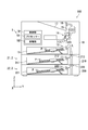
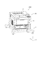
- FIG. 1 is a perspective view showing the configuration of an image forming apparatus set 200.
- the image forming apparatus set 200 includes an image forming apparatus 100 and a mounting table 3.
- the X-axis, the Y-axis and the Z-axis orthogonal to each other are described.
- the X and Y axes are parallel to the horizontal plane.
- the Z axis is parallel to the vertical direction.
- the positive direction side of the Y axis may be referred to as the back side, and the negative direction side of the Y axis may be referred to as the front side.
- the image forming apparatus 100 includes an apparatus main body 1 and one or more feeding units 2.
- the image forming apparatus 100 can be separated into the apparatus main body 1 and the feeding unit 2.
- the plurality of feeding units 2 can be separated into a single feeding unit 2.
- the apparatus body 1 is a printer.
- the feeding unit 2 includes a first feeding unit 21 and a second feeding unit 22.
- the first feeding unit 21 is disposed below the apparatus main body 1 and feeds a sheet to the apparatus main body 1.
- the first feeding unit 21 is fixed to the lower end of the apparatus main body 1.
- the second feeding unit 22 is disposed below the first feeding unit 21, and feeds a sheet to the apparatus main body 1 via the first feeding unit 21.
- the second feeding unit 22 is fixed to the lower end of the first feeding unit 21.
- the mounting table 3 is disposed below the image forming apparatus 100, and the image forming apparatus 100 is mounted. Specifically, the mounting table 3 is disposed below the second feeding unit 22, and the second feeding unit 22 is fixed to the mounting table 3.
- FIG. 2 is a side view showing the configuration of the image forming apparatus 100.
- the apparatus main body 1 includes a housing 10, a feeding cassette 11, a pickup roller 12, a conveyance unit L, an image forming unit 14, a fixing unit 15, a discharge roller pair 16, a discharge tray 17, and a control unit 18. Equipped with In the case 10, the feeding cassette 11, the pickup roller 12, the conveyance unit L, the image forming unit 14, the fixing unit 15, the discharge roller pair 16, and the control unit 18 are accommodated.
- the sheet P fed from the feeding cassette 11 by the pickup roller 12 is conveyed by the conveyance unit L to the image forming unit 14.
- the image forming unit 14 forms an image on the sheet P.
- the sheet P corresponds to an example of “recording medium”.
- the sheet P on which the image is formed is conveyed to the fixing unit 15.
- the fixing unit 15 heats and presses the sheet P, and fixes the image formed on the sheet P to the sheet P.
- the sheet P on which the image is fixed is discharged onto the discharge tray 17 by the discharge roller pair 16.
- the control unit 18 includes a processor 181 and a storage unit 182.
- the processor 181 includes, for example, a central processing unit (CPU).
- the storage unit 182 includes a memory such as a semiconductor memory, and may include a hard disk drive (HDD).
- the storage unit 182 stores a control program.
- the first feeding unit 21 includes a housing 210, a feeding cassette 211, a pickup roller 212, and a feeding roller pair 213.
- the housing 210 accommodates the feeding cassette 211, the pickup roller 212 and the feeding roller pair 213.
- the sheet P fed from the feeding cassette 211 by the pickup roller 212 is delivered to the transport unit L by the feeding roller pair 213.
- the second feeding unit 22 includes a housing 220, a feeding cassette 221, a pickup roller 222, and a feeding roller pair 223.
- the housing 220 accommodates the feeding cassette 221, the pickup roller 222, and the feeding roller pair 223.
- the sheet P fed by the pickup roller 222 from the feeding cassette 221 is fed by the feeding roller pair 223 to the conveyance unit L via the feeding roller pair 213 of the first feeding unit 21.
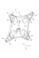
- FIG. 3 is a perspective view showing the configuration of the mounting table 3.
- the mounting table 3 includes a table main body 31, four supporting portions 32, and four legs 33.
- the image forming apparatus 100 is mounted on the table main body 31.
- the table body 31 is formed in a rectangular plate shape. Each of the four corners of the platform body 31 is supported by one of the four supports 32.
- the table body 31 has a mounting member 310.
- the mounting member 310 is formed in a rectangular flat plate shape, and the image forming apparatus 100 is mounted.
- the mounting member 310 further includes a locking mechanism R.
- the lock mechanism R restricts the movement of the image forming apparatus 100 with respect to the mounting table 3.
- the lock mechanism R has a first lock mechanism R1, a second lock mechanism R2, and a third lock mechanism R3.
- the first lock mechanism R1 may be described as a first lock mechanism 4 in the following description.
- the first lock mechanism 4 restricts the movement of the image forming apparatus 100 in the first direction D1 with respect to the mounting table 3.
- the first direction D1 indicates the negative direction of the Y axis.
- the configuration of the first lock mechanism 4 will be described in detail later with reference to FIG. 6, FIG. 7A and FIG. 7B.
- the second lock mechanism R2 includes an engagement member 311, an engagement member 312, an engagement member 313, and an engagement member 314. Each of the engaging member 311 to the engaging member 314 is formed on the top surface of the mounting member 310.
- the second lock mechanism R2 restricts the movement of the image forming apparatus 100 in the second direction D2 with respect to the mounting table 3.
- the second direction D2 indicates the positive direction of the Y axis. That is, the second direction D2 indicates the opposite direction to the first direction D1.
- the engagement member 311 is disposed at the end of the placement member 310 on the positive direction side of the X axis and on the positive direction side of the Y axis.
- the engagement member 312 is disposed at the end of the placement member 310 on the positive direction side of the X axis and on the negative direction side of the Y axis.
- the engagement member 313 is disposed at the end of the placement member 310 on the negative direction side of the X axis and on the positive direction side of the Y axis.
- the engagement member 314 is disposed at the end of the placement member 310 on the negative direction side of the X axis and the negative direction side of the Y axis.
- each of the engagement member 311 to the engagement member 314 is disposed at the four corners of the placement member 310.
- the configurations of the engagement members 311 to 314 will be described in detail later with reference to FIGS. 4A to 4D.
- Each of the engagement member 311 to the engagement member 314 corresponds to an example of the “second engagement member”.
- the third locking mechanism R3 has a convex member 315 and a convex member 316.
- the third lock mechanism R3 restricts the moving direction of the image forming apparatus 100 with respect to the mounting table 3 in the first direction D1 and the second direction D2. That is, the third lock mechanism R3 allows the image forming apparatus 100 to move relative to the mounting table 3 only in the first direction D1 and the second direction D2.
- the convex member 315 is disposed at the end of the placement member 310 in the positive direction side of the X axis and in the positive direction side of the Y axis. Specifically, the convex member 315 is disposed on the Y axis positive direction side with respect to the engagement member 311.
- the convex member 316 is disposed at the end of the placement member 310 on the positive direction side of the X axis and on the negative direction side of the Y axis. Specifically, the convex member 316 is disposed on the positive direction side of the Y axis with respect to the engagement member 312.
- the convex member 315 and the convex member 316 are inserted into the concave portion formed on the lower surface of the image forming apparatus 100. As a result, the convex member 315 and the convex member 316 restrict the moving direction of the image forming apparatus 100 with respect to the mounting table 3 in the first direction D1 and the second direction D2. The recess will be described in detail later with reference to FIG.
- the convex member 315 and the convex member 316 allow the image forming apparatus 100 to move relative to the mounting table 3 between the “first position” and the “second position” in the mounting table 3.
- the “first position” indicates the position where the image forming apparatus 100 is fixed to the mounting table 3.
- the “second position” indicates the position at which the image forming apparatus 100 is mounted on the mounting table 3. That is, the image forming apparatus 100 is mounted on the mounting table 3 by placing the image forming apparatus 100 on the “second position” of the mounting table 3 and moving the image forming apparatus 100 to the “first position” of the mounting table 3. It is fixed to The “first position” and the “second position” will be described in detail later with reference to FIGS. 8A to 11.
- the “first position” corresponds to an example of the “specific position”.
- Each of the four supports 32 supports one of the four corners of the base body 31.
- Each of the four support portions 32 is disposed so as to protrude in a direction away from the center of the base body 31 in the XY plane.
- Each of the four support portions 32 is formed in a trapezoidal shape in a plan view. The tip of each of the four supports 32 is supported by one of the four legs 33.
- Each of the four legs 33 supports one of the four supports 32. Each of the four legs 33 is placed on the floor surface. Each of the four legs 33 is configured such that the height of the mounting table 3 can be adjusted.
- the height of the mounting table 3 indicates the distance between the upper surface of the mounting table 3 and the floor surface in the Z-axis direction. That is, each of the four legs 33 is configured to be capable of adjusting the distance between the lower end of each of the four legs 33 and the upper surface of the mounting table 3.
- the first lock mechanism 4 restricts the movement of the image forming apparatus 100 in the first direction D1 with respect to the mounting table 3.
- the second locking mechanism R ⁇ b> 2 regulates movement of the image forming apparatus 100 in the second direction D ⁇ b> 2 with respect to the mounting table 3.
- the second direction D2 indicates the opposite direction to the first direction D1. Therefore, the movement of the image forming apparatus 100 with respect to the mounting table 3 can be restricted with a simple configuration. Therefore, the image forming apparatus 100 can be easily fixed to the mounting table 3.
- the third lock mechanism R3 regulates the moving direction of the image forming apparatus 100 with respect to the mounting table 3 in the first direction D1 and the second direction D2. Further, the first lock mechanism 4 restricts the movement of the image forming apparatus 100 in the first direction D1 with respect to the mounting table 3, and the second lock mechanism R2 moves in the second direction D2 with respect to the mounting table 3 of the image forming apparatus 100. Regulate the movement of Therefore, the movement of the image forming apparatus 100 with respect to the mounting table 3 can be restricted by the first lock mechanism 4, the second lock mechanism R2, and the third lock mechanism R3. Therefore, the image forming apparatus 100 can be fixed to the mounting table 3.
- the second lock mechanism R2 of the mounting table 3 includes the four engaging members 311 to the engaging members 314, but the present invention is not limited to this.
- the second locking mechanism R2 may include at least one engagement member. The smaller the number of engaging members, the simpler the configuration of the mounting table 3 can be.
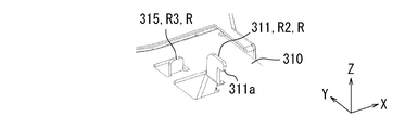
- FIGS. 3 and 4A to 4D are perspective views showing the configurations of the four engaging members 311 to engaging members 314 of the mounting table 3.
- FIG. 4A shows the configuration of the engagement member 311
- FIG. 4B shows the configuration of the engagement member 312
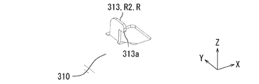
- FIG. 4C shows the configuration of the engagement member 313, and
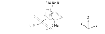
- FIG. The structure of the member 314 is shown.
- the engagement member 311 is erected on the placement member 310 in the positive direction of the Z axis.
- the engagement member 311 is a reverse L-shaped plate-like member.
- the engagement member 311 is disposed parallel to the YZ plane.
- the engagement member 311 includes an engagement portion 311a.
- the engagement portion 311 a is disposed at the tip of the engagement member 311 and protrudes in the negative direction of the Y axis.
- the convex member 315 is erected on the placement member 310 in the positive direction of the Z axis.
- the convex member 315 is a rectangular plate-like member.
- the convex member 315 is disposed parallel to the XZ plane.
- the engagement member 312 is erected on the placement member 310 in the positive direction of the Z axis.
- the engagement member 312 is a reverse L-shaped plate-like member.
- the engagement member 312 is disposed parallel to the YZ plane.
- the engagement member 312 includes an engagement portion 312a.
- the engagement portion 312 a is disposed at the tip of the engagement member 312 and protrudes in the negative direction of the Y axis.
- the convex member 316 is erected on the placement member 310 in the positive direction of the Z axis.
- the convex member 316 is a rectangular plate-like member.
- the convex member 316 is disposed parallel to the XZ plane.
- the engagement member 313 is erected on the placement member 310 in the positive direction of the Z axis.
- the engagement member 313 is a reverse L-shaped plate-like member.
- the engagement member 313 is disposed parallel to the YZ plane.
- the engagement member 313 includes an engagement portion 313a.
- the engagement portion 313a is disposed at the tip of the engagement member 313 and protrudes in the negative direction of the Y axis.
- the engagement member 314 is erected on the placement member 310 in the positive direction of the Z axis.
- the engagement member 314 is a reverse L-shaped plate-like member.
- the engagement member 314 is disposed parallel to the YZ plane.
- the engagement member 314 includes an engagement portion 314a.
- the engagement portion 314 a is disposed at the tip of the engagement member 314 and protrudes in the negative direction of the Y axis.
- FIG. 5 is a perspective view showing the configuration of the mounting table 3.
- FIG. 5 shows the mounting table 3 viewed from the negative direction of the Z axis.
- the mounting table 3 further includes four casters 34.
- Each of the four casters 34 is disposed on one of the four supports 32.
- the four casters 34 can support one of the four supports 32.
- Each of the four casters 34 can be placed on the floor surface. Specifically, when the distance between the lower end of each of the four legs 33 and the upper surface of the mounting table 3 is equal to or less than a predetermined distance, each of the four casters 34 is mounted on the floor surface, Support one of the four supports 32.
- the predetermined distance is, for example, 50 mm.
- FIG. 6 is a perspective view showing the configuration of the first lock mechanism 4 of the mounting table 3.
- the first lock mechanism 4 includes a projecting member 41, two biasing members 42, and a support member 43.
- the projecting member 41 is formed in a rectangular plate shape.
- the projecting member 41 has a support shaft 411 and two defining members 412.
- the support shaft 411 is disposed at the negative end of the Y-axis of the projecting member 41 and is parallel to the X-axis. Specifically, the support shaft 411 is disposed on one side of the projecting member 41. One side is located at the negative end of the Y-axis of the projecting member 41.
- the projecting member 41 is pivotable about the support shaft 411 in the direction D3. When the protruding member 41 protrudes from the mounting member 310 in the positive direction of the Z axis, the protruding member 41 restricts the movement of the image forming apparatus 100 in the first direction D1 with respect to the mounting table 3.
- Each of the two defining members 412 is erected on the lower surface side of the projecting member 41 in a direction orthogonal to the projecting member 41.
- the lower surface of the projecting member 41 indicates the surface on the side closer to the support member 43 among the two main surfaces of the projecting member 41.
- Each of the two defining members 412 is a cylindrical rod-like member, and is inserted into one of the two biasing members 42 to define the position of the one biasing member 42. That is, the biasing member 42 is disposed on the outer periphery of the defining member 412 and extends and contracts along the axial direction of the defining member 412.
- Each of the two biasing members 42 biases the side on the positive direction side of the Y axis of the projecting member 41 so as to protrude from the mounting member 310 in the positive direction of the Z axis.
- Each of the two biasing members 42 is, for example, a wound spring.
- the support member 43 is a flat member and supports the lower ends of the two biasing members 42.
- the support member 43 has two holes 431. Each of the two holes 431 is formed in a circular shape. The tip (lower end) of each of the two defining members 412 is inserted into each of the two holes 431.
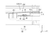
- FIG. 7A is a perspective sectional view showing the configuration of the first lock mechanism 4.
- FIG. 7B is a cross-sectional view showing the configuration of the first lock mechanism 4.
- 7A and 7B show a cross section in a plane including the axial center of the defining member 412 on the negative direction side of the Y axis of the two defining members 412 and parallel to the YZ plane.
- the tip of each of the two defining members 412 is inserted into one of the two holes 431. That is, the lower end of each of the two biasing members 42 is supported by the upper surface of the support member 43, and the upper end of each of the two biasing members 42 is supported by the lower surface of the projecting member 41. In this way, each of the two biasing members 42 is disposed in a compressed state between the support member 43 and the projecting member 41. The compressed state indicates that the biasing member 42 is shorter than the natural length of the biasing member 42.
- the projecting member 41 is biased by the biasing member 42 and pivots in the direction D4 about the pivot 411.
- the protrusion member 41 is further equipped with the contact part 41a.
- the contact portion 41 a is disposed on the side of the projecting member 41 away from the support shaft 411. That is, the contact portion 41 a is disposed at the end of the Y-axis in the positive direction in the projecting member 41.
- the positive direction end of the Y axis in the projecting member 41 corresponds to the “other one side” of the projecting member 41.
- the contact portion 41 a is a plate-like member extending in the X-axis direction.
- the contact portion 41 a is provided upright on the bottom surface side of the projecting member 41 (in the negative direction side of the Z axis) in the negative direction of the Z axis.
- the contact portion 41 a restricts the movement of the image forming apparatus 100 in the first direction D ⁇ b> 1 with respect to the mounting table 3 by coming into contact with the bottom plate of the image forming apparatus 100.
- the bottom plate of the image forming apparatus 100 will be described in detail later with reference to FIGS. 9A, 9B, 10A, and 10B.
- the biasing member 42 is disposed between the projecting member 41 and the support member 43. Therefore, the biasing member 42 can be realized with a simple configuration.
- the position of the biasing member 42 is defined by the defining member 412. Therefore, the biasing member 42 can reliably bias the projecting member 41.
- the tip of the defining member 412 is inserted into the hole 431 of the support member 43. Therefore, the biasing member 42 is disposed between the projecting member 41 and the support member 43 so as to be extensible. Therefore, the biasing member 42 can bias the projecting member 41 more reliably.
- the first lock mechanism 4 includes the two biasing members 42, but the present invention is not limited to this.
- the first locking mechanism 4 may include at least one biasing member 42. As the number of biasing members 42 is smaller, the configuration of the first lock mechanism 4 can be simplified.
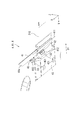
- FIG. 8A is a perspective view showing the positional relationship between the second feeding unit 22 of the image forming apparatus 100 and the mounting table 3.
- FIG. 8B is a perspective sectional view showing the “second position”.
- FIG. 8B shows a cross section in a plane parallel to the YZ plane, passing through the center position of the engaging member 312 in the X axis direction (thickness direction).
- the second feeding unit 22 of the image forming apparatus 100 is placed on the top surface of the placement table 3.
- the second feeding unit 22 of the image forming apparatus 100 is mounted on the upper surface of the mounting table 3 in the negative direction of the Z axis as shown in the direction D5.
- the second feeding unit 22 of the image forming apparatus 100 is placed at the “second position” of the placing table 3.
- the image forming apparatus 100 includes a plurality of second feeding units 22.
- the housing 220 of at least the lowermost second feeding unit 22 includes a hole 224A, a hole 224B, a hole 224C and a hole 224D, and a recess 225 and a recess 226.
- the holes 224A and the holes 224B are described, and the descriptions of the holes 224C and the holes 224D are omitted.
- the movement of the image forming apparatus 100 including the apparatus main body 1 and the plurality of second feeding units 22 on the mounting table 3 is restricted.
- the case where the image forming apparatus 100 is mounted at the “second position” of the mounting table 3 will be described below.
- Each of the holes 224A to 224D is formed at a position facing one of the engagement members 311 to 314.
- Each of the holes 224A to 224D has a rectangular shape and extends along the first direction D1.
- One of the engagement members 311 to 314 is inserted into each of the holes 224A to 224D.
- the holes 221A to 224D correspond to an example of the “first engagement member”.
- the concave portion 225 is formed at a position facing the convex member 315, and is formed to extend along the first direction D1.
- the convex member 315 is inserted into the recess 225.
- the recess 226 is formed at a position facing the convex member 316.
- the convex member 316 is inserted into the recess 226.
- the “second position” indicates the position of the mounting table 3 such that the convex member 315 is inserted into the concave portion 225 and the convex member 316 is inserted into the concave portion 226.
- the convex member 315 is inserted into the recess 225, and the convex member 316 is inserted into the recess 226.
- the moving direction of the image forming apparatus 100 with respect to the mounting table 3 is limited to the first direction D1 and the second direction D2. Therefore, the third lock mechanism R3 can be realized with a simple configuration.
- FIG. 9A is a perspective sectional view showing the IX-IX section (see FIGS. 8A and 8B) of the second feeding unit 22 of the image forming apparatus 100 and the mounting table 3.
- the second feeding unit 22 of the image forming apparatus 100 is mounted at the “second position” of the mounting table 3.
- 9B is a cross-sectional view showing an IX-IX cross section (see FIGS. 8A and 8B) of the image forming apparatus 100 and the mounting table 3 shown in FIG. 9A.
- FIG. 9B the vicinity of the first lock mechanism 4 is shown enlarged.
- the housing 220 further includes a bottom plate 227, a bottom plate 228, and an opening 229.
- the bottom plate 227 and the bottom plate 228 are disposed on the bottom of the housing 220.
- the bottom plate 227 is a plate-like member which is disposed on the positive direction side of the Y-axis with respect to the bottom plate 228 in the housing 220 and extends in the X-axis direction.
- the bottom plate 228 is a plate-like member which is disposed on the negative direction side of the Y axis with respect to the bottom plate 227 in the housing 220 and extends in the X axis direction.
- the opening 229 is a rectangular opening formed between the bottom plate 227 and the bottom plate 228.
- the bottom plate 227 presses the projecting member 41 of the first lock mechanism 4 in the negative direction of the Z axis. Do. As a result, the protruding member 41 does not protrude to the inside of the housing 220. That is, the first lock mechanism 4 does not restrict the movement of the image forming apparatus 100 in the first direction D1 with respect to the mounting table 3.
- the projecting member 41 is freely retractable into the housing 220 from the opening 229 (in the positive direction of the Z axis).
- FIG. 10A is a perspective sectional view showing the IX-IX section (see FIGS. 8A and 8B) of the second feeding unit 22 of the image forming apparatus 100 and the mounting table 3.
- the second feeding unit 22 of the image forming apparatus 100 is moved to the “first position” of the mounting table 3.
- 10B is a cross-sectional view showing a cross section (see FIGS. 8A and 8B) of the second feeding unit 22 and the mounting table 3 of the image forming apparatus 100 shown in FIG. 10A.
- FIG. 10B the vicinity of the first lock mechanism 4 is shown enlarged.
- the image forming apparatus 100 is disposed at the “first position” of the mounting table 3 by moving the image forming apparatus 100 mounted at the “second position” of the mounting table 3 in the second direction D2. Specifically, the second feeding unit 22 of the image forming apparatus 100 slides on the mounting member 310 of the mounting table 3 and is disposed from the “second position” to the “first position” of the mounting table 3. Be done. As shown in FIG. 10B, when the image forming apparatus 100 is mounted at the “first position” of the mounting table 3, the projecting member 41 is the inside of the housing 220 from the opening 229 (the positive direction side of the Z axis Protruding into the
- the projecting member 41 when the projecting member 41 is in the projecting state, the projecting member 41 pivots counterclockwise around the support shaft 411, and the abutting portion 41a abuts on the end of the bottom plate 227 in the negative direction of the Y axis.
- the first lock mechanism 4 restricts the movement of the image forming apparatus 100 in the first direction D1 with respect to the mounting table 3.
- the protruding member 41 protrudes from the opening 229 to the inside of the housing 220.
- the movement of the image forming apparatus 100 in the first direction D1 with respect to the mounting table 3 can be restricted.
- the projecting member 41 protrudes from the opening 229 to the inside of the housing 220 by being moved from the “second position” to the “first position”. In the first position, the opening 229 faces the projecting member 41. Therefore, by moving the image forming apparatus 100 from the “second position” to the “first position”, the movement of the image forming apparatus 100 in the first direction D1 relative to the mounting table 3 can be easily restricted.
- the movement of the image forming apparatus 100 with respect to the mounting table 3 can be restricted by the contact portion 41 a of the projecting member 41 being in contact with the bottom plate 227. Therefore, the movement of the image forming apparatus 100 in the first direction D1 with respect to the mounting table 3 can be reliably restricted.
- FIG. 11 is a perspective sectional view in which a part of the cross section of the image forming apparatus 100 and the mounting table 3 is enlarged.
- the second feeding unit 22 of the image forming apparatus 100 is disposed at the “first position” of the mounting table 3.
- FIG. 11 shows a cross section in a plane parallel to the YZ plane, passing through the center position of the engaging member 312 in the X-axis direction (thickness direction).
- the engaging portion 312 a of the engaging member 312 engages with the peripheral wall of the hole 224 B. .
- the following operations are performed along with the movement of the image forming apparatus 100 from the "second position" to the "first position". That is, the engaging portion 311a of the engaging member 311 engages with the peripheral wall of the hole 224A, and the engaging portion 313a of the engaging member 313 engages with the peripheral wall of the hole 224C. The mating portion 314a and the peripheral wall of the hole 224D are engaged.
- the image forming apparatus 100 is mounted along with the movement from the “second position” to the “first position”.
- the convex member 316 of the mounting base 3 moves in the negative direction of the Y axis with respect to the recess 226 of the housing 220.
- the convex member 315 of the mounting table 3 is a mounting table as the image forming apparatus 100 moves from the “second position” to the “first position” while maintaining the state of being inserted into the recess 225 of the housing 220.
- the three convex members 315 move in the negative direction of the Y axis with respect to the recess 225 of the housing 220.
- the image forming apparatus 100 is directed to the first position with respect to the mounting table 3. Is moved in the second direction D2.
- the engaging member 311 and the peripheral wall of the hole 224A are engaged.
- the engaging member 312 engages with the peripheral wall of the hole 224B.
- the engagement member 313 and the peripheral wall of the hole 224C are engaged.
- the engaging member 314 engages with the peripheral wall of the hole 224D. Therefore, the movement of the image forming apparatus 100 in the second direction D2 with respect to the mounting table 3 can be easily restricted.
- FIG. 12 is a perspective view showing the configuration of the image forming apparatus set 200A.
- the image forming apparatus set 200 ⁇ / b> A includes the apparatus main body 1 and the mounting table 3. That is, while the image forming apparatus 100 of the image forming apparatus set 200 shown in FIG. 1 includes the apparatus main body 1 and the feeding unit 2, the image forming apparatus 100 of the image forming apparatus set 200A shown in FIG. It is different in that it is configured only by the device body 1. In the following description, differences between the image forming apparatus set 200A and the image forming apparatus set 200 will be mainly described.
- the image forming apparatus set 200 ⁇ / b> A includes the apparatus main body 1 and the mounting table 3.
- the apparatus body 1 is mounted on the mounting table 3.
- the device body 1 has a housing 10.
- the bottom surface of the housing 10 is fixed to the mounting table 3.
- the bottom of the apparatus main body 1 has the hole 224A, the hole 224B, the hole 224C, the hole 224D, the recess 225, and the recess 226 as in the configuration of the second feeding unit 22 described with reference to FIGS. 8A and 8B. And are equipped.
- the bottom surface of the case 10 of the device body 1 is fixed to the mounting table 3.
- the apparatus main body 1 can be mounted on the mounting table 3, and movement of the apparatus main body 1 on the mounting table 3 can be regulated, and printing on paper is unnecessary. Only the main body 1 can be fixed to the mounting table 3 and used.
- the image forming apparatus 100 is a printer, but the present invention is not limited to this.
- the image forming apparatus 100 may include the image forming unit 14.
- the image forming apparatus 100 may be a multifunction peripheral.
- the image forming apparatus 100 may be a copying machine.
- the contact portion 41a of the projecting member 41 of the first lock mechanism 4 is the bottom plate of the image forming apparatus 100.
- the first lock mechanism 4 may restrict the movement of the image forming apparatus 100 in the first direction D1 with respect to the mounting table 3.
- the contact portion 41 a of the protruding member 41 of the first lock mechanism 4 may contact the bottom plate 228 of the image forming apparatus 100.
- the contact portion 41 a of the projecting member 41 of the first lock mechanism 4 may abut on the frame member of the image forming apparatus 100.
- the engaging portion 312a of the engaging member 312 engages with the peripheral wall of the hole 224B.
- the second lock mechanism R2 may restrict movement of the image forming apparatus 100 in the second direction D2 with respect to the mounting table 3.
- the engagement member 312 and the bottom plate 228 of the image forming apparatus 100 may be engaged.
- the engagement member 312 and the frame member of the image forming apparatus 100 may be engaged.
- the present invention relates to a mounting table and an image forming apparatus set, and has industrial applicability.
Landscapes
- Physics & Mathematics (AREA)
- General Physics & Mathematics (AREA)
- Engineering & Computer Science (AREA)
- Multimedia (AREA)
- Signal Processing (AREA)
- Electrophotography Configuration And Component (AREA)
- Accessory Devices And Overall Control Thereof (AREA)
- Casings For Electric Apparatus (AREA)
Abstract
画像形成装置セット(200)は、画像形成装置(100)と、画像形成装置(100)が載置される載置台(3)とを備える。載置台(3)は、ロック機構(R)を備える。ロック機構(R)は、画像形成装置(100)が載置台(3)の第1位置に載置された場合に、画像形成装置(100)の載置台(3)に対する移動を規制する。ロック機構(R)は、第1ロック機構(4)と、第2ロック機構(R2)とを有する。第1ロック機構(4)は、画像形成装置(100)の載置台(3)に対する第1方向(D1)への移動を規制する。第2ロック機構(R2)は、画像形成装置(100)の載置台(3)に対する第2方向(D2)への移動を規制する。第2方向(D2)は、第1方向(D1)と反対方向を示す。
Description
本発明は、載置台、及び画像形成装置セットに関する。
特許文献1の載置台は、画像形成装置の下方に配置され、板状部材と、複数の係合部材とを備える。板状部材は、少なくとも画像形成装置の床投影面積よりも大きい。複数の係合部材は、板状部材に設けられる。画像形成装置は、ベースフレームと、複数の被係合部材とを備える。複数の被係合部材の各々は、ベースフレームに設けられる。複数の被係合部材の各々と複数の係合部材の各々とは係合する。具体的には、ボルト留めによって、複数の被係合部材の各々と複数の係合部材の各々とが係合する。
しかしながら、特許文献1に記載の載置台では、画像形成装置を載置台に固定するために手間がかかる。
本発明は、上記課題に鑑みてなされたものであり、画像形成装置を載置台に容易に固定することが可能な載置台、及び画像形成装置セットを提供することを目的としている。
本発明に係る載置台は、画像形成装置が載置される載置台であって、ロック機構を備える。前記ロック機構は、前記画像形成装置が前記載置台の第1位置に載置された場合に、前記画像形成装置の前記載置台に対する移動を規制する。前記ロック機構は、第1ロック機構と、第2ロック機構とを有する。前記第1ロック機構は、前記画像形成装置の前記載置台に対する第1方向への移動を規制する。前記第2ロック機構は、前記画像形成装置の前記載置台に対する第2方向への移動を規制する。前記第2方向は、前記第1方向と反対方向を示す。
本発明に係る画像形成装置セットは、画像形成装置と、前記画像形成装置が載置される載置台とを備える。前記載置台は、ロック機構を備える。前記ロック機構は、前記画像形成装置が前記載置台の特定位置に載置された場合に、前記画像形成装置の前記載置台に対する移動を規制する。前記ロック機構は、第1ロック機構と、第2ロック機構とを有する。前記第1ロック機構は、前記画像形成装置の前記載置台に対する第1方向への移動を規制する。前記第2ロック機構は、前記画像形成装置の前記載置台に対する第2方向への移動を規制する。前記第2方向は、前記第1方向と反対方向を示す。
本発明に係る載置台、及び画像形成装置セットによれば、画像形成装置を載置台に容易に固定できる。
以下、本発明の実施形態について、図面(図1~図12)を参照しながら説明する。なお、図中、同一又は相当部分については同一の参照符号を付して説明を繰り返さない。
まず、図1を参照して、本発明の実施形態に係る画像形成装置セット200の構成について説明する。図1は、画像形成装置セット200の構成を示す斜視図である。図1に示すように、画像形成装置セット200は、画像形成装置100と、載置台3とを備える。
図1には、互いに直交するX軸、Y軸及びZ軸を記載している。X軸及びY軸は、水平面と平行である。Z軸は、鉛直方向と平行である。以下の説明において、Y軸の正方向側を背面側といい、Y軸の負方向側を前面側という場合がある。
画像形成装置100は、装置本体1と、1つ又は複数の給送ユニット2とを備える。画像形成装置100は、装置本体1と給送ユニット2に分離可能である。複数の給送ユニット2は、単体の給送ユニット2に分離可能である。装置本体1は、プリンターである。給送ユニット2は、第1給送ユニット21と、第2給送ユニット22とを備える。第1給送ユニット21は、装置本体1の下側に配置され、装置本体1に用紙を給送する。第1給送ユニット21は、装置本体1の下端に固定される。第2給送ユニット22は、第1給送ユニット21の下側に配置され、第1給送ユニット21を経由して、装置本体1に用紙を給送する。第2給送ユニット22は、第1給送ユニット21の下端に固定される。
載置台3は、画像形成装置100の下側に配置され、画像形成装置100が載置される。具体的には、載置台3は、第2給送ユニット22の下側に配置され、第2給送ユニット22は、載置台3に固定される。
次に、図1及び図2を参照して、画像形成装置100の構成について説明する。図2は、画像形成装置100の構成を示す側面図である。図2に示すように、装置本体1は、筐体10、給送カセット11、ピックアップローラー12、搬送部L、画像形成部14、定着部15、排出ローラー対16、排出トレイ17及び制御部18を備える。筐体10には、給送カセット11、ピックアップローラー12、搬送部L、画像形成部14、定着部15、排出ローラー対16及び制御部18が収納される。
給送カセット11からピックアップローラー12によって繰り出された用紙Pは、搬送部Lによって画像形成部14まで搬送される。画像形成部14は、用紙Pに画像を形成する。用紙Pは、「記録媒体」の一例に相当する。
画像が形成された用紙Pは、定着部15まで搬送される。定着部15は、用紙Pを加熱及び加圧し、用紙Pに形成された画像を用紙Pに定着する。画像が定着された用紙Pは、排出ローラー対16によって排出トレイ17に排出される。
制御部18は、プロセッサー181及び記憶部182を備える。プロセッサー181は、例えばCPU(Central Processing Unit)を備える。記憶部182は、半導体メモリーのようなメモリーを備え、HDD(Hard Disk Drive)を備えてもよい。記憶部182は、制御プログラムを記憶している。
第1給送ユニット21は、筐体210、給送カセット211、ピックアップローラー212及び給送ローラー対213を備える。筐体210は、給送カセット211、ピックアップローラー212及び給送ローラー対213を収納する。給送カセット211からピックアップローラー212によって繰り出された用紙Pは、給送ローラー対213によって、搬送部Lに送出される。
第2給送ユニット22は、筐体220、給送カセット221、ピックアップローラー222及び給送ローラー対223を備える。筐体220は、給送カセット221、ピックアップローラー222及び給送ローラー対223を収納する。給送カセット221からピックアップローラー222によって繰り出された用紙Pは、給送ローラー対223によって、第1給送ユニット21の給送ローラー対213を経由して搬送部Lに送出される。
次に、図1~図3を参照して、本発明の実施形態に係る載置台3の構成について説明する。図3は、載置台3の構成を示す斜視図である。図3に示すように、載置台3は、台本体31と、4つの支持部32と、4つの脚体33とを備える。
台本体31には、画像形成装置100が載置される。台本体31は、矩形板状に形成される。台本体31の4隅の各々は、4つの支持部32のうちの1つの支持部32に支持される。台本体31は、載置部材310を有する。
載置部材310は、矩形平板状に形成され、画像形成装置100が載置される。載置部材310は、ロック機構Rを更に備える。ロック機構Rは、画像形成装置100の載置台3に対する移動を規制する。ロック機構Rは、第1ロック機構R1、第2ロック機構R2及び第3ロック機構R3を有する。第1ロック機構R1を、以下の説明では、第1ロック機構4と記載する場合がある。
第1ロック機構4は、画像形成装置100の載置台3に対する第1方向D1への移動を規制する。第1方向D1は、Y軸の負方向を示す。第1ロック機構4の構成については、後述にて図6、図7A及び図7Bを参照して詳細に説明する。
第2ロック機構R2は、係合部材311、係合部材312、係合部材313及び係合部材314を有する。係合部材311~係合部材314の各々は、載置部材310の上面に形成される。第2ロック機構R2は、画像形成装置100の載置台3に対する第2方向D2への移動を規制する。第2方向D2は、Y軸の正方向を示す。すなわち、第2方向D2は、第1方向D1と反対方向を示す。
係合部材311は、載置部材310において、X軸の正方向側で、且つY軸の正方向側の端部に配置される。係合部材312は、載置部材310において、X軸の正方向側で且つY軸の負方向側の端部に配置される。係合部材313は、載置部材310において、X軸の負方向側で且つY軸の正方向側の端部に配置される。係合部材314は、載置部材310において、X軸の負方向側で且つY軸の負方向側の端部に配置される。すなわち、係合部材311~係合部材314の各々は、載置部材310の四隅に配置される。係合部材311~係合部材314の構成については、後述にて図4A~図4Dを参照して詳細に説明する。係合部材311~係合部材314の各々は、「第2係合部材」の一例に相当する。
第3ロック機構R3は、凸部材315及び凸部材316を有する。第3ロック機構R3は、画像形成装置100の載置台3に対する移動方向を第1方向D1及び第2方向D2に制限する。すなわち、第3ロック機構R3は、画像形成装置100を載置台3に対して第1方向D1及び第2方向D2のみに移動可能にする。凸部材315は、載置部材310において、X軸の正方向側で且つY軸の正方向側の端部に配置される。具体的には、凸部材315は、係合部材311に対してY軸の正方向側に配置される。凸部材316は、載置部材310において、X軸の正方向側で且つY軸の負方向側の端部に配置される。具体的には、凸部材316は、係合部材312に対してY軸の正方向側に配置される。
凸部材315及び凸部材316は、画像形成装置100の下面に形成された凹部に挿入される。その結果、凸部材315及び凸部材316は、画像形成装置100の載置台3に対する移動方向を第1方向D1及び第2方向D2に規制する。凹部については、後述にて図11を参照して詳細に説明する。
更に具体的には、凸部材315及び凸部材316は、載置台3における「第1位置」と「第2位置」との間で画像形成装置100が載置台3に対して移動可能にする。「第1位置」は、画像形成装置100が載置台3に固定される位置を示す。「第2位置」は、画像形成装置100が載置台3に載置される位置を示す。すなわち、画像形成装置100を載置台3の「第2位置」に載置して、画像形成装置100を載置台3の「第1位置」に移動することによって、画像形成装置100が載置台3に固定される。「第1位置」及び「第2位置」については、後述にて図8A~図11を参照して詳細に説明する。「第1位置」は、「特定位置」の一例に相当する。
4つの支持部32の各々は、台本体31の四隅のうちの1つを支持する。4つの支持部32の各々は、X-Y平面における台本体31の中心から離間する方向に突出して配置される。4つの支持部32の各々は、平面視台形状に形成される。4つの支持部32の各々の先端部は、4つの脚体33のうちの1つによって支持される。
4つの脚体33の各々は、4つの支持部32のうちの1つを支持する。4つの脚体33の各々は、床面上に載置される。4つの脚体33の各々は、載置台3の高さが調整可能に構成される。載置台3の高さは、載置台3の上面と床面とのZ軸方向の距離を示す。すなわち、4つの脚体33の各々は、4つの脚体33の各々の下端と載置台3の上面との間の距離を調整可能に構成される。
以上、図1~図3を参照して説明したように、本発明の実施形態では、第1ロック機構4が画像形成装置100の載置台3に対する第1方向D1への移動を規制し、第2ロック機構R2が画像形成装置100の載置台3に対する第2方向D2への移動を規制する。また、第2方向D2は、第1方向D1と反対方向を示す。よって、簡素な構成で、画像形成装置100の載置台3に対する移動を規制できる。したがって、画像形成装置100が載置台3に容易に固定可能になる。
また、第3ロック機構R3は、画像形成装置100の載置台3に対する移動方向を第1方向D1及び第2方向D2に規制する。また、第1ロック機構4が、画像形成装置100の載置台3に対する第1方向D1への移動を規制し、第2ロック機構R2が、画像形成装置100の載置台3に対する第2方向D2への移動を規制する。よって、第1ロック機構4と、第2ロック機構R2と、第3ロック機構R3とによって画像形成装置100の載置台3に対する移動を規制できる。したがって、画像形成装置100を載置台3に固定できる。
なお、本発明の実施形態では、載置台3の第2ロック機構R2が4つの係合部材311~係合部材314を有するが、本発明はこれに限定されない。第2ロック機構R2が少なくとも1つの係合部材を備えればよい。係合部材の個数が少ない程、載置台3の構成を簡素化できる。
次に、図3、図4A~図4Dを参照して、載置台3の4つの係合部材311~係合部材314の構成について説明する。図4A~図4Dは、載置台3の4つの係合部材311~係合部材314の構成を示す斜視図である。具体的には、図4Aは、係合部材311の構成を示し、図4Bは、係合部材312の構成を示し、図4Cは、係合部材313の構成を示し、図4Dは、係合部材314の構成を示す。
図4Aに示すように、係合部材311は、載置部材310に対してZ軸の正方向に立設される。係合部材311は、逆L字状の板状部材である。係合部材311は、Y-Z平面と平行に配置される。係合部材311は、係合部311aを備える。係合部311aは、係合部材311の先端に配置され、Y軸の負方向に突出する。
凸部材315は、載置部材310に対してZ軸の正方向に立設される。凸部材315は、矩形板状部材である。凸部材315は、X-Z平面と平行に配置される。
図4Bに示すように、係合部材312は、載置部材310に対してZ軸の正方向に立設される。係合部材312は、逆L字状の板状部材である。係合部材312は、Y-Z平面と平行に配置される。係合部材312は、係合部312aを備える。係合部312aは、係合部材312の先端に配置され、Y軸の負方向に突出する。
凸部材316は、載置部材310に対してZ軸の正方向に立設される。凸部材316は、矩形板状部材である。凸部材316は、X-Z平面と平行に配置される。
図4Cに示すように、係合部材313は、載置部材310に対してZ軸の正方向に立設される。係合部材313は、逆L字状の板状部材である。係合部材313は、Y-Z平面と平行に配置される。係合部材313は、係合部313aを備える。係合部313aは、係合部材313の先端に配置され、Y軸の負方向に突出する。
図4Dに示すように、係合部材314は、載置部材310に対してZ軸の正方向に立設される。係合部材314は、逆L字状の板状部材である。係合部材314は、Y-Z平面と平行に配置される。係合部材314は、係合部314aを備える。係合部314aは、係合部材314の先端に配置され、Y軸の負方向に突出する。
次に、図3~図5を参照して、載置台3について更に説明する。図5は、載置台3の構成を示す斜視図である。図5は、Z軸の負方向から見た載置台3を示している。図5に示すように、載置台3は、4つのキャスター34を更に備える。
4つのキャスター34の各々は、4つの支持部32のうちの1つに配置される。4つのキャスター34は、4つの支持部32のうちの1つを支持可能である。4つのキャスター34の各々は、床面上に載置可能である。具体的には、4つの脚体33の各々の下端と載置台3の上面との間の距離が所定距離以下である場合に、4つのキャスター34の各々は、床面上に載置され、4つの支持部32のうちの1つを支持する。所定距離は、例えば50mmである。
次に、図1~図3、図6、図7A及び図7Bを参照して、第1ロック機構4の構成について説明する。図6は、載置台3の第1ロック機構4の構成を示す斜視図である。図6に示すように、第1ロック機構4は、突出部材41と、2つの付勢部材42と、支持部材43とを備える。
突出部材41は、矩形板状に形成される。突出部材41は、支軸411と2つの規定部材412を有する。支軸411は、突出部材41のY軸の負方向端に配置され、X軸に平行である。具体的には、支軸411は、突出部材41の1つの辺に配置される。1つの辺は、突出部材41のY軸の負方向端に位置する。突出部材41は支軸411を中心に方向D3に回動自在である。突出部材41が載置部材310からZ軸の正方向に突出している場合には、突出部材41は、画像形成装置100の載置台3に対する第1方向D1への移動を規制する。
2つの規定部材412の各々は、突出部材41の下面側に、突出部材41に対して直交する方向に立設される。突出部材41の下面は,突出部材41の2つの主面のうちの支持部材43と近接する側の面を示す。2つの規定部材412の各々は、円柱状の棒状部材であり、2つの付勢部材42のうちの1つの付勢部材42に挿通され、1つの付勢部材42の位置を規定する。すなわち、付勢部材42は規定部材412の外周に配置され、規定部材412の軸方向に沿って伸縮する。
2つの付勢部材42の各々は、突出部材41のY軸の正方向側の辺が載置部材310からZ軸の正方向に突出するように付勢する。2つの付勢部材42の各々は、例えば、巻きバネである。
支持部材43は、平板状部材であり、2つの付勢部材42の下端を支持する。支持部材43は、2つの孔431を有する。2つの孔431の各々は、円形状に形成される。2つの孔431の各々には、2つの規定部材412の各々の先端(下端)が挿通される。
図7Aは、第1ロック機構4の構成を示す斜視断面図である。図7Bは、第1ロック機構4の構成を示す断面図である。なお、図7A及び図7Bは、2つの規定部材412のうちのY軸の負方向側の規定部材412の軸心を含みY-Z平面と平行な平面における断面を示す。図7A及び図7Bでは、2つの規定部材412の各々の先端は、2つの孔431のうちの1つの孔431に挿通されている。すなわち、2つの付勢部材42の各々の下端は、支持部材43の上面で支持され、2つの付勢部材42の各々の上端は、突出部材41の下面で支持される。このようにして、2つの付勢部材42の各々は、支持部材43と突出部材41との間に圧縮状態で配置される。圧縮状態とは、付勢部材42が、付勢部材42の自然長より短い状態を示す。
図7Bに示すように、突出部材41は、付勢部材42によって付勢され、支軸411を中心に方向D4に回動している。
また、図7A及び図7Bに示すように、突出部材41は、当接部41aを更に備える。当接部41aは、突出部材41において支軸411と離間する側に配置される。すなわち、当接部41aは、突出部材41においてY軸の正方向端に配置される。突出部材41におけるY軸の正方向端は、突出部材41の「他の1つの辺」に相当する。上述したように、「1つの辺」は、突出部材41のY軸の負方向端に位置するので、「1つの辺」と「他の1つの辺」とは対向する。当接部41aは、X軸方向に延びる板状部材である。当接部41aは、突出部材41の底面側に(Z軸の負方向側に)、Z軸の負方向に向けて立設されている。
当接部41aは、画像形成装置100の底板と当接することによって、画像形成装置100の載置台3に対する第1方向D1への移動を規制する。画像形成装置100の底板については、後述にて図9A、図9B、図10A及び図10Bを参照して詳細に説明する。
以上、図1~図3、図6、図7A及び図7Bを参照して説明したように、付勢部材42は、突出部材41と支持部材43との間に配置される。したがって、付勢部材42を簡素な構成で実現できる。
また、付勢部材42の位置が規定部材412によって規定される。したがって、付勢部材42が突出部材41を確実に付勢できる。
更に、規定部材412の先端が支持部材43の孔431に挿通される。よって、付勢部材42が、突出部材41と支持部材43との間に伸縮自在に配置される。したがって、付勢部材42が突出部材41を更に確実に付勢できる。
なお、本発明の実施形態では、第1ロック機構4は、2つの付勢部材42を備えるが、本発明はこれに限定されない。第1ロック機構4が、少なくとも1つの付勢部材42を備えればよい。付勢部材42の個数が少ない程、第1ロック機構4の構成を簡素化できる。
次に、図1~図4D、図8A及び図8Bを参照して、「第2位置」について説明する。「第2位置」は、画像形成装置100を載置台3に載置する位置を示す。図8Aは、画像形成装置100の第2給送ユニット22と載置台3との位置関係を示す斜視図である。図8Bは、「第2位置」を示す斜視断面図である。なお、図8Bは、係合部材312のX軸方向(厚み方向)の中心位置を通り、Y-Z平面と平行な面における断面を示す。図8Aに示すように、画像形成装置100の第2給送ユニット22は、載置台3の上面に載置される。具体的には、画像形成装置100の第2給送ユニット22は、方向D5に示すようにZ軸の負方向に向けて、載置台3の上面に載置される。
更に具体的には、図8Bに示すように、画像形成装置100の第2給送ユニット22は、載置台3の「第2位置」に載置される。図1に示したように、画像形成装置100が複数段の第2給送ユニット22を備える。この場合、図8Bにおいて、少なくとも最下段の第2給送ユニット22の筐体220は、孔部224A、孔部224B、孔部224C及び孔部224Dと、凹部225及び凹部226とを備える。図8Bには、孔部224A及び孔部224Bを記載し、孔部224C及び孔部224Dの記載は省略している。このような構成とすることで、装置本体1と複数段の第2給送ユニット22からなる画像形成装置100が、載置台3上での移動を規制される。画像形成装置100が載置台3の「第2位置」に載置される場合について以下に説明する。
孔部224A~孔部224Dの各々は、係合部材311~係合部材314のうちの1つの係合部材と対向する位置に形成される。孔部224A~孔部224Dの各々は、矩形状であり、第1方向D1に沿って延びる。孔部224A~孔部224Dの各々には、係合部材311~係合部材314のうちの1つの係合部材が挿入される。孔部221A~孔部224Dは、「第1係合部材」の一例に相当する。
凹部225は、凸部材315と対向する位置に形成され、第1方向D1に沿って延びて形成されている。凹部225には、凸部材315が挿入される。凹部226は、凸部材316と対向する位置に形成される。凹部226には、凸部材316が挿入される。
「第2位置」とは、凹部225に凸部材315が挿入され、凹部226に凸部材316が挿入されるような載置台3の位置を示す。このように、画像形成装置100の第2給送ユニット22を載置台3の「第2位置」に載置することによって、孔部224A~孔部224Dの各々には、係合部材311~係合部材314のうちの1つの係合部材が挿入される。
以上、図1~図4D、図8A及び図8Bを参照して説明したように、本発明の実施形態では、凹部225に凸部材315が挿入され、凹部226に凸部材316が挿入される。これによって、画像形成装置100の載置台3に対する移動方向を第1方向D1及び第2方向D2に制限する。したがって、簡素な構成で第3ロック機構R3を実現できる。
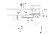
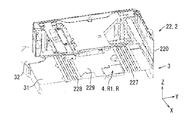
次に、図1~図3、図6~図7B、図9A~図10Bを参照して、画像形成装置100を載置台3に固定する際の第1ロック機構4の動作について説明する。図9Aは、画像形成装置100の第2給送ユニット22と載置台3とのIX-IX断面(図8A及び図8B参照)を示す斜視断面図である。図9Aでは、画像形成装置100の第2給送ユニット22は、載置台3の「第2位置」に載置されている。図9Bは、図9Aに示す画像形成装置100と載置台3とのIX-IX断面(図8A及び図8B参照)を示す断面図である。図9Bでは、第1ロック機構4の近傍を拡大して示している。図9Aに示すように、筐体220は、底板227、底板228及び開口229を更に有する。
底板227及び底板228は、筐体220の底面に配置される。底板227は、筐体220において底板228に対してY軸の正方向側に配置され、X軸方向に延びる板状部材である。底板228は、筐体220において底板227に対してY軸の負方向側に配置され、X軸方向に延びる板状部材である。開口229は、底板227と底板228との間に形成される矩形状の開口である。
図9Bに示すように、画像形成装置100が載置台3の第2位置に載置された場合には、底板227が第1ロック機構4の突出部材41をZ軸の負方向に向けて押圧する。その結果、突出部材41は、筐体220の内側に突出しない。すなわち、第1ロック機構4は、画像形成装置100の載置台3に対する第1方向D1への移動を規制していない。突出部材41は、開口229から筐体220の内側に(Z軸の正方向側に)出没自在である。
図10Aは、画像形成装置100の第2給送ユニット22と載置台3とのIX-IX断面(図8A及び図8B参照)を示す斜視断面図である。図10Aでは、画像形成装置100の第2給送ユニット22は、載置台3の「第1位置」に移動されている。図10Bは、図10Aに示す画像形成装置100の第2給送ユニット22と載置台3とのIX-IX断面(図8A及び図8B参照)を示す断面図である。図10Bでは、第1ロック機構4の近傍を拡大して示している。
載置台3の「第2位置」に載置された画像形成装置100を、第2方向D2に移動することによって、画像形成装置100は、載置台3の「第1位置」に配置される。具体的には、画像形成装置100の第2給送ユニット22は、載置台3の載置部材310上を摺動して、載置台3の「第2位置」から「第1位置」に配置される。図10Bに示すように、画像形成装置100が載置台3の「第1位置」に載置された場合には、突出部材41は、開口229から筐体220の内側(Z軸の正方向側に)に突出する。
すなわち、突出部材41は、突出状態のとき、支軸411を中心として反時計回りに回動し、当接部41aが、底板227のY軸の負方向側の端部と当接する。その結果、第1ロック機構4は、画像形成装置100の載置台3に対する第1方向D1への移動を規制する。
以上、図1~図3、図6~図7B、図9A~図10Bを参照して説明したように、本発明の実施形態では、突出部材41が開口229から筐体220の内側に突出することによって、画像形成装置100の載置台3に対する第1方向D1への移動を規制できる。
また、画像形成装置100は、「第2位置」から「第1位置」に移動されることによって、突出部材41が開口229から筐体220の内側に突出する。第1位置では、開口229が突出部材41と対向する。したがって、画像形成装置100を「第2位置」から「第1位置」に移動することによって、画像形成装置100の載置台3に対する第1方向D1への移動を容易に規制できる。
更に、突出部材41の当接部41aが底板227に当接することによって、画像形成装置100の載置台3に対する移動を規制できる。したがって、画像形成装置100の載置台3に対する第1方向D1への移動を確実に規制できる。
次に、図1~図4D、図8A、図8B及び図11を参照して、画像形成装置100を載置台3に固定する際の4つの係合部材311~係合部材314の作用について説明する。図11は、画像形成装置100と載置台3との断面の一部を拡大した斜視断面図である。図11では、図10A及び図10Bと同様に、画像形成装置100の第2給送ユニット22は、載置台3の「第1位置」に配置されている。なお、図11は、係合部材312のX軸方向(厚み方向)の中心位置を通り、Y-Z平面と平行な面における断面を示す。図11に示すように、画像形成装置100が載置台3の「第1位置」に配置されている場合には、係合部材312の係合部312aと孔部224Bの周壁とが係合する。
係合部材312の係合部312aと孔部224Bの周壁との係合と同様に、画像形成装置100の「第2位置」から「第1位置」への移動に伴って、以下の動作が行われる。すなわち、係合部材311の係合部311aと孔部224Aの周壁とが係合し、係合部材313の係合部313aと孔部224Cの周壁とが係合し、係合部材314の係合部314aと孔部224Dの周壁とが係合する。
また、載置台3の凸部材316が筐体220の凹部226に挿入された状態を維持したまま、画像形成装置100の「第2位置」から「第1位置」への移動に伴って、載置台3の凸部材316は、筐体220の凹部226に対してY軸の負方向に移動している。載置台3の凸部材315は、筐体220の凹部225に挿入された状態を維持したまま、画像形成装置100の「第2位置」から「第1位置」への移動に伴って、載置台3の凸部材315は、筐体220の凹部225に対してY軸の負方向に移動している。
以上、図1~図4D、図8A、図8B及び図11を参照して説明したように、本発明の実施形態では、画像形成装置100が「第1位置」に向けて載置台3に対して第2方向D2に移動される。これによって、係合部材311と孔部224Aの周壁とが係合する。係合部材312と孔部224Bの周壁とが係合する。係合部材313と孔部224Cの周壁とが係合する。係合部材314と孔部224Dの周壁とが係合する。したがって、画像形成装置100の載置台3に対する第2方向D2への移動を容易に規制できる。
次に、図1と図12とを参照して、本発明の他の実施形態に係る画像形成装置セット200Aの構成について説明する。図12は、画像形成装置セット200Aの構成を示す斜視図である。図12に示すように、画像形成装置セット200Aは、装置本体1と載置台3とで構成されている。すなわち、図1に示す画像形成装置セット200の画像形成装置100が、装置本体1と給送ユニット2とを備えるのに対して、図12に示す画像形成装置セット200Aの画像形成装置100が、装置本体1のみで構成される点で相違している。以下の説明では、画像形成装置セット200Aが画像形成装置セット200と相違する点について主に説明する。
図12に示すように、画像形成装置セット200Aは、装置本体1と載置台3とで構成されている。装置本体1は、載置台3に載置される。装置本体1は、筐体10を有する。筐体10の底面は、載置台3に固定される。装置本体1の底面には、図8A、図8Bで説明した第2給送ユニット22の構成と同様に、孔部224A、孔部224B、孔部224C及び孔部224Dと、凹部225及び凹部226とが備えられている。
以上、図1及び図12を参照して説明したように、本発明の他の実施形態では、装置本体1の筐体10の底面が載置台3に固定される。このように構成することで、装置本体1のみを載置台3に載置し、載置台3上での装置本体1の移動を規制することができ、用紙への印字が不要な態様において、装置本体1のみを載置台3に固定して使用することができる。
以上、図面を参照しながら本発明の実施形態について説明した。ただし、本発明は、上記の実施形態に限られるものではなく、その要旨を逸脱しない範囲で種々の態様において実施することが可能である(例えば、下記に示す(1)~(3))。図面は、理解し易くするために、それぞれの構成要素を主体に模式的に示しており、図示された各構成要素の厚み、長さ、個数等は、図面作成の都合上から実際とは異なる場合がある。また、上記の実施形態で示す各構成要素の形状、寸法等は一例であって、特に限定されるものではなく、本発明の構成から実質的に逸脱しない範囲で種々の変更が可能である。
(1)図1を参照して説明したように、画像形成装置100はプリンターであるが、本発明はこれに限定されない。画像形成装置100は画像形成部14を備えればよい。例えば、画像形成装置100が、複合機である形態でもよい。また、例えば、画像形成装置100が、複写機である形態でもよい。
(2)図1~図3、図6~図7B、図9A~図10Bを参照して説明したように、第1ロック機構4の突出部材41の当接部41aが画像形成装置100の底板227に当接するが、本発明はこれに限定されない。第1ロック機構4が画像形成装置100の載置台3に対する第1方向D1への移動を規制すればよい。例えば、第1ロック機構4の突出部材41の当接部41aが画像形成装置100の底板228に当接してもよい。また、例えば、第1ロック機構4の突出部材41の当接部41aが画像形成装置100の枠部材に当接してもよい。
(3)図1~図4D、図8A、図8B及び図11を参照して説明したように、係合部材312の係合部312aと孔部224Bの周壁とが係合するが、本発明はこれに限定されない。第2ロック機構R2が画像形成装置100の載置台3に対する第2方向D2への移動を規制すればよい。例えば、係合部材312と画像形成装置100の底板228とが係合してもよい。また、例えば、係合部材312と画像形成装置100の枠部材とが係合してもよい。
本発明は、載置台、及び画像形成装置セットに関するものであり、産業上の利用可能性を有する。
Claims (13)
- 画像形成装置が載置される載置台に対し、前記画像形成装置の移動を規制するロック機構を備え、
前記ロック機構は、
前記画像形成装置の前記載置台に対する第1方向への移動を規制する第1ロック機構と、
前記画像形成装置の前記載置台に対する第2方向への移動を規制する第2ロック機構とを有し、
前記第2方向は、前記第1方向と反対方向を示し、
前記ロック機構は、前記画像形成装置が前記載置台の第1位置に載置された場合に、前記画像形成装置の前記載置台に対する移動を規制する、載置台。 - 前記画像形成装置の前記載置台に対する移動方向を前記第1方向及び前記第2方向に制限する第3ロック機構を更に備える、請求項1に記載の載置台。
- 前記第3ロック機構は、凸部材を更に備え、
前記画像形成装置は、前記第1方向に沿って延びる凹部を備え、
前記第3ロック機構は、前記凸部材が前記凹部に挿入することによって、前記画像形成装置の前記載置台に対する移動方向を前記第1方向及び前記第2方向に規制する、請求項2に記載の載置台。 - 前記画像形成装置は、用紙に画像を形成する本体と、前記本体に前記用紙を給送する複数の給送ユニットに分離可能であり、
前記本体の底面と、前記給送ユニットの底面には、それぞれ前記凹部が備えられている、請求項3に記載の載置台。 - 前記画像形成装置は、筐体を更に備え、
前記筐体は、前記筐体の底面に、底板と開口とを有し、
前記第1ロック機構は、
前記開口から前記筐体の内側に出没自在である突出部材と、
前記突出部材を前記開口に向けて付勢する付勢部材と
を備える、請求項1に記載の載置台。 - 前記突出部材は、矩形板状に形成され、
前記突出部材の1つの辺を支軸として、前記突出部材は回動自在であり、
前記突出部材が突出状態のときに、前記突出部材の他の1つの辺が前記底板に当接し、
前記他の1つの辺は、前記1つの辺と対向する、請求項5に記載の載置台。 - 前記第1ロック機構は、前記付勢部材の下端を支持する板状の支持部材を更に備え、
前記付勢部材は、前記支持部材と前記突出部材との間に配置される、請求項5に記載の載置台。 - 前記第1ロック機構は、前記付勢部材の位置を規定する規定部材を有し、
前記規定部材は、前記突出部材の下面に立設された棒状部材であり、
前記付勢部材は、巻きバネであり、
前記規定部材は、前記付勢部材に挿通される、請求項7に記載の載置台。 - 前記支持部材は、孔を有し、
前記規定部材は、前記孔に挿通される、請求項8に記載の載置台。 - 前記画像形成装置は、前記第1位置と相違する第2位置に載置され、前記第2位置から前記第1位置に移動されることによって、前記突出部材が前記開口から前記筐体の内側に突出し、
前記第1位置では、前記開口が前記突出部材と対向し、
前記第2位置では、前記底板が前記突出部材を押圧する、請求項5に記載の載置台。 - 前記画像形成装置が載置される板状の載置部材を更に備え、
前記画像形成装置は、第1係合部材を更に備え、
前記第2ロック機構は、前記画像形成装置が前記第1位置に向けて前記第2方向に移動されることによって、前記第1係合部材に係合する第2係合部材を有し、
前記第2係合部材は、前記載置部材の上面に形成される、請求項10に記載の載置台。 - 前記画像形成装置は、用紙に画像を形成する本体と、前記本体に前記用紙を給送する複数の給送ユニットに分離可能であり、
前記本体の底面と、前記給送ユニットの底面には、それぞれ前記第1係合部材が備えられている、請求項11に記載の載置台。 - 画像形成装置と、
前記画像形成装置が載置される載置台と
を備える画像形成装置セットであって、
前記載置台は、前記画像形成装置の前記載置台に対する移動を規制するロック機構を備え、
前記ロック機構は、
前記画像形成装置の前記載置台に対する第1方向への移動を規制する第1ロック機構と、
前記画像形成装置の前記載置台に対する第2方向への移動を規制する第2ロック機構とを有し、
前記第2方向は、前記第1方向と反対方向を示し、
前記ロック機構は、前記画像形成装置が前記載置台の特定位置に載置された場合に、前記画像形成装置の前記載置台に対する移動を規制する、画像形成装置セット。
Priority Applications (2)
| Application Number | Priority Date | Filing Date | Title |
|---|---|---|---|
| US16/957,705 US11022930B2 (en) | 2017-12-25 | 2018-10-04 | Mounting base and image forming apparatus set |
| JP2019562764A JPWO2019130707A1 (ja) | 2017-12-25 | 2018-10-04 | 載置台、及び画像形成装置セット |
Applications Claiming Priority (2)
| Application Number | Priority Date | Filing Date | Title |
|---|---|---|---|
| JP2017-247805 | 2017-12-25 | ||
| JP2017247805 | 2017-12-25 |
Publications (1)
| Publication Number | Publication Date |
|---|---|
| WO2019130707A1 true WO2019130707A1 (ja) | 2019-07-04 |
Family
ID=67066837
Family Applications (1)
| Application Number | Title | Priority Date | Filing Date |
|---|---|---|---|
| PCT/JP2018/037203 Ceased WO2019130707A1 (ja) | 2017-12-25 | 2018-10-04 | 載置台、及び画像形成装置セット |
Country Status (3)
| Country | Link |
|---|---|
| US (1) | US11022930B2 (ja) |
| JP (1) | JPWO2019130707A1 (ja) |
| WO (1) | WO2019130707A1 (ja) |
Citations (6)
| Publication number | Priority date | Publication date | Assignee | Title |
|---|---|---|---|---|
| JPS5849484U (ja) * | 1981-09-26 | 1983-04-04 | 富士通株式会社 | 装置の取付構造 |
| JPH01140169A (ja) * | 1987-11-26 | 1989-06-01 | Konica Corp | 2分割型複写装置 |
| JPH02222979A (ja) * | 1989-02-23 | 1990-09-05 | Mita Ind Co Ltd | 画像形成装置 |
| JPH02120876U (ja) * | 1989-03-15 | 1990-09-28 | ||
| JP2006350084A (ja) * | 2005-06-17 | 2006-12-28 | Fuji Xerox Co Ltd | 画像形成装置及び載置台 |
| US20100308533A1 (en) * | 2009-06-05 | 2010-12-09 | Kabushiki Kaisha Toshiba | Stabilizer, image forming apparatus, and stabilizer mounting method |
Family Cites Families (5)
| Publication number | Priority date | Publication date | Assignee | Title |
|---|---|---|---|---|
| US4969010A (en) | 1987-11-26 | 1990-11-06 | Konica Corporation | Copying machine |
| EP0384467B1 (en) | 1989-02-23 | 1994-07-20 | Mita Industrial Co. Ltd. | Image forming apparatus |
| US5975515A (en) * | 1997-02-21 | 1999-11-02 | Hewlett-Packard Company | System for designating paper cassettes in printers and copiers |
| JPH10246999A (ja) | 1997-03-05 | 1998-09-14 | Fuji Xerox Co Ltd | 画像形成装置の転倒防止装置 |
| JP4058390B2 (ja) * | 2003-06-30 | 2008-03-05 | キヤノン株式会社 | ロック機構およびこれを備えた給紙装置、画像形成装置 |
-
2018
- 2018-10-04 JP JP2019562764A patent/JPWO2019130707A1/ja active Pending
- 2018-10-04 WO PCT/JP2018/037203 patent/WO2019130707A1/ja not_active Ceased
- 2018-10-04 US US16/957,705 patent/US11022930B2/en not_active Expired - Fee Related
Patent Citations (6)
| Publication number | Priority date | Publication date | Assignee | Title |
|---|---|---|---|---|
| JPS5849484U (ja) * | 1981-09-26 | 1983-04-04 | 富士通株式会社 | 装置の取付構造 |
| JPH01140169A (ja) * | 1987-11-26 | 1989-06-01 | Konica Corp | 2分割型複写装置 |
| JPH02222979A (ja) * | 1989-02-23 | 1990-09-05 | Mita Ind Co Ltd | 画像形成装置 |
| JPH02120876U (ja) * | 1989-03-15 | 1990-09-28 | ||
| JP2006350084A (ja) * | 2005-06-17 | 2006-12-28 | Fuji Xerox Co Ltd | 画像形成装置及び載置台 |
| US20100308533A1 (en) * | 2009-06-05 | 2010-12-09 | Kabushiki Kaisha Toshiba | Stabilizer, image forming apparatus, and stabilizer mounting method |
Also Published As
| Publication number | Publication date |
|---|---|
| US11022930B2 (en) | 2021-06-01 |
| JPWO2019130707A1 (ja) | 2021-01-07 |
| US20200363766A1 (en) | 2020-11-19 |
Similar Documents
| Publication | Publication Date | Title |
|---|---|---|
| JP7124311B2 (ja) | 給送装置、及び画像形成装置 | |
| JP6347181B2 (ja) | シート載置装置および画像形成装置 | |
| JP6364989B2 (ja) | 記録装置 | |
| JP2018193147A (ja) | シート収容装置およびプリント装置 | |
| JP6384381B2 (ja) | 給紙カセット及び画像形成装置 | |
| JP6079685B2 (ja) | フローティングコネクタおよび画像形成装置 | |
| JP5810064B2 (ja) | シート受渡装置 | |
| JPWO2019130707A1 (ja) | 載置台、及び画像形成装置セット | |
| JP7027723B2 (ja) | インクジェット記録装置、及び記録ヘッドの位置調整方法 | |
| JP2002019973A (ja) | 用紙載置トレイ | |
| JP7566487B2 (ja) | 転倒防止装置、シート給送装置及び画像形成装置 | |
| JP6705511B2 (ja) | ユニット筐体、及び画像形成装置 | |
| JP2005096950A (ja) | シート整合装置 | |
| JP7214994B2 (ja) | 画像形成装置 | |
| JP2016114893A (ja) | 画像形成装置 | |
| JP2007119198A (ja) | 画像形成装置 | |
| JP2020033113A (ja) | 給紙装置および画像形成装置 | |
| JP2004004367A (ja) | フレーム構造及びこれを用いた処理装置 | |
| JP4270039B2 (ja) | 調整部品の位置決め装置 | |
| JP2023147732A (ja) | 画像形成装置 | |
| JP2021119309A (ja) | フレームの締結構造及び読取装置 | |
| JP2017171479A (ja) | シート収容装置、画像形成装置 | |
| JP2018188269A (ja) | 給紙カセット及びこれを備えた画像形成装置 | |
| JP2004202765A (ja) | 画像形成装置用フレーム | |
| JP2016000636A (ja) | 画像形成装置 |
Legal Events
| Date | Code | Title | Description |
|---|---|---|---|
| 121 | Ep: the epo has been informed by wipo that ep was designated in this application |
Ref document number: 18897541 Country of ref document: EP Kind code of ref document: A1 |
|
| ENP | Entry into the national phase |
Ref document number: 2019562764 Country of ref document: JP Kind code of ref document: A |
|
| NENP | Non-entry into the national phase |
Ref country code: DE |
|
| 122 | Ep: pct application non-entry in european phase |
Ref document number: 18897541 Country of ref document: EP Kind code of ref document: A1 |