WO2019130635A1 - 水処理方法及び装置 - Google Patents
水処理方法及び装置 Download PDFInfo
- Publication number
- WO2019130635A1 WO2019130635A1 PCT/JP2018/028680 JP2018028680W WO2019130635A1 WO 2019130635 A1 WO2019130635 A1 WO 2019130635A1 JP 2018028680 W JP2018028680 W JP 2018028680W WO 2019130635 A1 WO2019130635 A1 WO 2019130635A1
- Authority
- WO
- WIPO (PCT)
- Prior art keywords
- water
- polymer flocculant
- treated
- mol
- cationic polymer
- Prior art date
- Legal status (The legal status is an assumption and is not a legal conclusion. Google has not performed a legal analysis and makes no representation as to the accuracy of the status listed.)
- Ceased
Links
Images


Classifications
-
- B—PERFORMING OPERATIONS; TRANSPORTING
- B01—PHYSICAL OR CHEMICAL PROCESSES OR APPARATUS IN GENERAL
- B01D—SEPARATION
- B01D21/00—Separation of suspended solid particles from liquids by sedimentation
- B01D21/01—Separation of suspended solid particles from liquids by sedimentation using flocculating agents
-
- B—PERFORMING OPERATIONS; TRANSPORTING
- B01—PHYSICAL OR CHEMICAL PROCESSES OR APPARATUS IN GENERAL
- B01D—SEPARATION
- B01D21/00—Separation of suspended solid particles from liquids by sedimentation
- B01D21/02—Settling tanks with single outlets for the separated liquid
- B01D21/08—Settling tanks with single outlets for the separated liquid provided with flocculating compartments
-
- B—PERFORMING OPERATIONS; TRANSPORTING
- B01—PHYSICAL OR CHEMICAL PROCESSES OR APPARATUS IN GENERAL
- B01D—SEPARATION
- B01D21/00—Separation of suspended solid particles from liquids by sedimentation
- B01D21/24—Feed or discharge mechanisms for settling tanks
-
- C—CHEMISTRY; METALLURGY
- C02—TREATMENT OF WATER, WASTE WATER, SEWAGE, OR SLUDGE
- C02F—TREATMENT OF WATER, WASTE WATER, SEWAGE, OR SLUDGE
- C02F1/00—Treatment of water, waste water, or sewage
- C02F1/52—Treatment of water, waste water, or sewage by flocculation or precipitation of suspended impurities
- C02F1/54—Treatment of water, waste water, or sewage by flocculation or precipitation of suspended impurities using organic material
- C02F1/56—Macromolecular compounds
-
- C—CHEMISTRY; METALLURGY
- C02—TREATMENT OF WATER, WASTE WATER, SEWAGE, OR SLUDGE
- C02F—TREATMENT OF WATER, WASTE WATER, SEWAGE, OR SLUDGE
- C02F1/00—Treatment of water, waste water, or sewage
- C02F1/58—Treatment of water, waste water, or sewage by removing specified dissolved compounds
- C02F1/62—Heavy metal compounds
-
- C—CHEMISTRY; METALLURGY
- C02—TREATMENT OF WATER, WASTE WATER, SEWAGE, OR SLUDGE
- C02F—TREATMENT OF WATER, WASTE WATER, SEWAGE, OR SLUDGE
- C02F1/00—Treatment of water, waste water, or sewage
- C02F1/58—Treatment of water, waste water, or sewage by removing specified dissolved compounds
- C02F1/62—Heavy metal compounds
- C02F1/64—Heavy metal compounds of iron or manganese
Definitions
- the present invention relates to a water treatment method and apparatus by coagulation sedimentation.
- Coagulative precipitation is widely used as one of the unit operations in water treatment.
- a flocculant such as an inorganic flocculant or a polymer flocculant is added to the suspension water containing the suspended matter, and the suspended matter is flocculated by appropriately stirring, thereby forming an aggregate (" Form a flocculated floc). Then, the aggregate is precipitated and solid-liquid separated from the suspension water to obtain clear treated water.
- the sludge blanket method is known as one of such aggregation precipitation methods.
- a suspended and packed layer of aggregates ie, a sludge blanket
- the fine suspended matter in the suspension water is separated by filtration by flowing into and through the sludge blanket.
- Patent Document 1 discloses, among the sludge blanket methods, a technique related to a method of performing stirring and granulation in a coagulation sedimentation tank.
- a cationic polymer flocculant is added to the suspension water, and then an anionic polymer flocculant is added to form, stir and granulate aggregates in the flocculation settling tank, solid-liquid separation It has been described that.
- high-density spherical aggregates (pellets) are formed by the crosslinking action of the anionic polymer flocculant and the cationic polymer flocculant and the mechanical dewatering action by the stirring in the sedimentation tank.
- the sedimentation of the pellets is much higher than that of conventional flocculated flocs, and forming the sludge blanket from the pellets enables processing at a higher linear velocity (LV) than that of the conventional sludge blanket method. Therefore, the water area load can be increased compared to the conventional sludge blanket method, and the settling tank can be more compact.
- the sludge blanket formed of the pellet may be called a pellet blanket.
- Patent Document 2 the pH of the purified waste sludge is adjusted to an alkaline region, an inorganic flocculant is mixed, and an anionic polymer is added and stirred in a high-speed granulation precipitation concentration tank to form a highly granulated product.
- a method is disclosed.
- the interface of the sludge blanket disperses, and the flocculated floc forming the sludge blanket is treated water And the quality of the treated water may deteriorate.
- An object of the present invention is to provide an anionic polymer by adding a cationic polymer flocculant and an anionic polymer flocculant in this order in a water treatment method in which metal ion-containing water is subjected to alkaline aggregation precipitation at pH 8 or more. It is an object of the present invention to provide a water treatment method capable of obtaining clearer treated water as compared with the case of adding only a flocculant.
- Another object of the present invention is to provide a water treatment device suitable for carrying out such a water treatment method.
- a water treatment method comprising:
- Alkali addition means for adding an alkali to the water to be treated containing metal ions;
- a cationic polymer flocculant addition unit which is provided downstream of the alkali addition unit, adds a cationic polymer flocculant having a cation group ratio of 30 mol% or less to the water to be treated;
- Anionic polymer flocculant addition means provided downstream of the cationic polymer flocculant addition means for adding an anionic polymer flocculant having an anion group ratio of 10 mol% or more to the water to be treated;
- a sludge blanket and a layer of clear water are formed from treated water provided downstream of the anionic polymer flocculant addition means, treated water is obtained from the layer of clear water, and sludge is obtained from the sludge blanket , Sludge blanket type sedimentation tank,
- a water treatment device comprising
- an anionic polymer is obtained by adding a cationic polymer flocculant and an anionic polymer flocculant in this order. It is possible to provide a water treatment method capable of obtaining clearer treated water as compared with the case of adding only the flocculant.
- FIG. 1 It is a figure which shows schematic structure of an example of the water treatment apparatus which concerns on this invention. It is a graph which shows the relationship between the cation group ratio of a cationic polymer flocculent, and the suspended matter (SS) density
- the water treatment method according to the present invention comprises steps i to iii.
- step i a metal hydroxide is precipitated as a suspended substance at a pH of 8 or more by adding an alkali to the metal ion-containing treated water, that is, raw water.
- step ii after adding a cationic polymer flocculant to the water to be treated obtained from step i, an aggregate of the suspended matter is formed by adding an anionic polymer flocculant. Stirring may be carried out as appropriate or simultaneously with the addition of the respective polymeric flocculants.
- a cationic polymer flocculant having a cation group ratio of 30 mol% or less, preferably 15 mol% or less, more preferably 8 mol% or less is used.
- the cationic group ratio can be 3 mol% or more.
- an anionic polymer flocculant having an anionic group ratio of 10 mol% or more is added. This makes it possible to form better aggregates, is easy to process with high LV, and it is easy to obtain a clearer treated water.
- the anionic group ratio can be, for example, 50 mol% or less, further 45 mol% or less, and specifically 41 mol% or less.
- a sludge blanket and a layer of clear water are formed from the water to be treated obtained from step ii.
- Treated water is obtained from the layer of clear water.
- sludge can be obtained from a sludge blanket.
- the aggregates can be further concentrated by sedimentation and the concentrated aggregates can be discharged as sludge.
- Raw water to be treated in the present invention is water containing metal ions.
- water containing metal ions that form insoluble metal hydroxides at a pH of 8 or more can be used.
- the metal is, for example, zinc, nickel, cobalt, iron, copper, lead, cadmium, manganese and the like.
- drainage such as plating drainage of a plating plant, flue gas desulfurization drainage of a power generation plant, and flushing drainage of a waste incineration plant can be mentioned. If metal ions in waste water are low (for example, 10 mg / L or less) or if substances other than metal ions are to be removed, perform aggregation treatment by adding an inorganic coagulant as necessary. May be
- alkali to be added in step i alkalis known in the field of flocculation and precipitation such as caustic soda, slaked lime, sodium carbonate and the like can be used.
- the waste water may contain an organic acid such as citric acid, and a compound which forms a complex such as EDTA (ethylenediaminetetraacetic acid) or ammonia.
- an iron salt such as ferric chloride may be added to carry out alkaline aggregation and precipitation, whereby the complex forming compound may be effectively removed.
- aluminum salts such as PAC (polyaluminum chloride) and sulfate bands can also be used, but in the case of aluminum salts, since the aggregation pH is in the neutral region of 6.0 to 8.5, It is preferable to use an iron salt capable of aggregating even in the alkaline region.
- the cationic polymer flocculant having a cationic group ratio of 30 mol% or less comprises a copolymer of a cationic monomer and a nonionic monomer. And the ratio of the cationic monomer among the cationic monomer and the nonionic monomer which comprises this copolymer, ie, a cation group ratio, is 30 mol% or less.
- the cationic monomer include dimethylaminoethyl acrylate / methyl chloride quaternary salt (DAA) and dimethylaminoethyl methacrylate methyl chloride quaternary salt (DAM).
- DAA dimethylaminoethyl acrylate / methyl chloride quaternary salt
- DAM dimethylaminoethyl methacrylate methyl chloride quaternary salt
- acrylamide can be mentioned, for example.
- the weight average molecular weight of the cationic polymer flocculant can be, for example, 7,000,000 or more or 10,000,000 or more, and can be 15,000,000 or less. Generally, the larger the molecular weight, the better the flocculating ability, but since the optimum molecular weight also differs depending on the type of waste water and the type of sludge dewatering, it is better to select each case accordingly.
- the amount of the cationic polymer flocculant added to the water to be treated is preferably, for example, 0.3 to 10 mg / L.
- the addition amount may be more than 10 mg / L, but in that case, the effect of increasing the particle size of the aggregate (pellets) with respect to the increase of the addition amount is small. Further, by setting the addition amount to 10 mg / L or less, it is possible to easily prevent the influence on the post-stage equipment, for example, the blockage of the membrane filtration equipment and the decrease in the sludge removability after dehydration.
- the cationic polymer flocculant is preferably added to the water to be treated in the form of a solution previously dissolved in water.
- concentration of the cationic polymer flocculant in the solution is, for example, 0.05 to 0.3 w / v%.
- the anionic polymer flocculant As the anionic polymer flocculant, those known in the field of flocculation and precipitation can be appropriately used.
- the anionic polymer flocculant is preferably a medium to strong anion polymer flocculant which functions particularly effectively as a flocculant in the alkaline region. Specifically, an anionic polymer flocculant having an anionic group ratio of 10 mol% or more is used.
- anionic polymer flocculant one comprising a copolymer of an anionic monomer and a nonionic monomer can be used.
- the anionic monomer is, for example, acrylic acid.
- the nonionic monomer is, for example, acrylamide.
- the weight average molecular weight of the anionic polymer flocculant can be, for example, 10,000,000 or more, or 15,000,000 or more, and can be 25,000,000 or less.
- the larger the molecular weight the better the aggregation ability.
- the optimum molecular weight varies depending on the type of drainage and sludge dewatering model, it is better to select each time according to them.
- the amount of the anionic polymer flocculant added to the water to be treated is preferably, for example, 0.3 to 10 mg / L.
- the addition amount is 0.3 mg / L or more, it is easy to increase the aggregate (which may be a pellet).
- the addition amount may be more than 10 mg / L, but in that case, the effect of increasing the particle size of the aggregate with respect to the increase of the addition amount is small. Further, by setting the addition amount to 10 mg / L or less, it is possible to easily prevent the influence on the post-stage equipment, for example, the blockage of the membrane filtration equipment and the decrease in the sludge removability after dehydration.
- the anionic polymer flocculant is preferably added to the water to be treated in the form of a solution previously dissolved in water.
- the concentration of the anionic polymer flocculant in the solution is 0.05 to 0.3 w / v%.
- the anionic polymer flocculant comprises a copolymer of an anionic monomer and a nonionic monomer
- the anionic group ratio is an anionic monomer among the anionic monomer and the nonionic monomer constituting this copolymer. Means the percentage of
- the aggregates are retained in the sedimentation tank to form a sludge blanket which is a floating and dense layer of the aggregates, and the aggregates (typically fine flocs) and suspended matter (flowing in later)
- a sludge blanket type settling tank that captures SS
- the treated water containing the aggregates flows upward, the settling speed of the aggregates and the rising speed of the treated water are balanced, and the aggregates are densely floated.
- the sludge blanket type settling tanks it is also possible to use, in particular, a granulated settling tank in which the sludge blanket is stirred to perform granulation (the pellet blanket is formed).
- sludge blanket type sedimentation tank those known in the field of coagulated sedimentation can be appropriately used.
- a water treatment apparatus includes an alkali addition means, a cationic polymer flocculant addition means, an anionic polymer flocculant addition means, and a sludge blanket type precipitation tank.
- An alkali addition means is comprised so that an alkali may be added to the to-be-processed water containing a metal ion.
- the cationic polymer flocculant addition means is provided downstream of the alkali addition means, and is configured to add a cationic polymer flocculant having a cation group ratio of 30 mol% or less to the water to be treated.
- the anionic polymer coagulant addition means is provided downstream of the cationic polymer coagulant addition means, and is configured to add an anionic polymer coagulant having an anion group ratio of 10 mol% or more to the water to be treated. Ru.
- the sludge blanket type sedimentation tank is provided downstream of the anionic polymer flocculant addition means, and forms a sludge blanket and a layer of clear water from the water to be treated, and obtains treated water from the layer of the clear water, It is configured to obtain sludge from a sludge blanket.
- downstream means downstream with respect to the flow of treated water.
- FIG. 1 An example of a water treatment device is shown in FIG.
- This water treatment device can be referred to in detail as a “flocculating and settling device” and is hereinafter referred to as a “flocculating and settling device”.
- the coagulation / sedimentation apparatus comprises a primary water tank 10 for aeration of raw water and pH adjustment, a primary flocculation tank 20 for mixing raw water after pH adjustment and a cationic polymer flocculant, and aggregation and granulation operations in the interior. And a settling tank 30 with a stirrer.
- the settling tank 30 is a sludge blanket type settling tank.
- Raw water is supplied to the raw water tank 10 from the line L1.
- caustic soda is added as an alkali to the raw water, and the pH of the resulting treated water is adjusted to 8 or more.
- the line L7 connected to the raw water tank 10 is used as an alkali addition means. By this pH adjustment, the metal oxide is precipitated and a suspended substance is formed in the water to be treated.
- the pH of the water to be treated can be measured using a pH meter (indicated by "pH" in the figure) as appropriate.
- the line L7 does not have to be connected to the raw water tank 10, and may be connected to the line L1, for example.
- a container (not shown) containing alkali or an aqueous solution thereof can be connected to the line L7.
- the raw water tank 10 is supplied with air from the blower B through a line L6 in order to aerate the raw water.
- the to-be-processed water obtained from the raw water tank 10 is sent to the latter stage primary aggregation tank 20 through the line L2.
- the pump P and the flow meter FI can be provided as appropriate in the line L2.
- a cationic polymer flocculant having a cation group ratio of 30 mol% or less is added to the water to be treated which has flowed into the primary flocculation tank 20, and the aggregate of the suspended matter, typically a fibrous primary flocculate floe. Is formed.
- the line L8 connected to the primary coagulation tank 20 is used as a cationic polymer flocculant addition means.
- stirring can be appropriately performed using a stirring blade 21 in the primary aggregation tank.
- the line L8 does not have to be connected to the primary aggregation tank 20, and may be connected to the line L2, for example.
- a container (not shown) that accommodates the cationic polymer flocculant or an aqueous solution thereof can be connected to the line L8.
- an anionic polymer flocculant is added before the water to be treated flows into the settling tank 30. Is added.
- the line L9 connected to the line L3 is used as an anionic polymer coagulant addition means.
- a water tank (not shown) may be provided in the middle of the line L3, and the line L9 may be connected to the water tank.
- the container (not shown) which accommodates anionic polymer flocculent or its aqueous solution can be connected to the line L9.
- the to-be-processed water to which the anionic polymer flocculant is added flows upward from the bottom surface into the sedimentation tank 30 through the line L3.
- the upward flow of the treated water forms a sludge blanket.
- the settling tank 30 is a granulating type settling tank, and granulation of the aggregates is carried out by agitation of the sludge blanket, in particular, coarsening of the aggregates by slow agitation, mechanical dewatering action, rolling movement, etc.
- a pellet of aggregates is formed.
- the settling tank 30 is provided with a stirring blade 31 for stirring the water to be treated, which is driven by a motor M.
- the granulated pellets form a sludge blanket Z1 and a layer Z2 of clear water is formed on the sludge blanket.
- clear water is discharged to the line L4 as treated water.
- a concentration unit 33 communicating with the inside of the settling tank 30 through the opening 32 is provided.
- Excess sludge (pellets floating above the sludge blanket Z1) in the sedimentation tank 30 is made to overflow and flow into the concentration unit 33, and is sedimented and concentrated in the concentration unit 33.
- a line L5 for extracting concentrated sludge from the layer Z3 of concentrated sludge (pellets concentrated to a high concentration) deposited in the concentration unit 33 is connected to the lower part of the concentration unit 33, and the concentrated sludge is coagulated and settled from the line L5. Discharged to the outside of the
- solid-liquid separation can be performed by forming aggregates of metal hydroxide having a high sedimentation rate.
- a sludge blanket-type settling tank (which may be a granulated settling tank) can be used.
- the residence time of the cationic polymer flocculant in the coagulating and precipitating apparatus before the addition of the anionic polymer flocculant is preferably 1 minute or more, more preferably 2 minutes or more.
- a cationic polymer flocculant may be added in the raw water tank 10 without providing the primary coagulation tank 20. That is, the line L8 may be connected to the raw water tank 10.
- the line L8 may be connected to the raw water tank 10.
- many raw water tanks are large, and primary aggregation flocs formed by the addition of a cationic polymer flocculant tend to stay in the corners of the raw water tanks.
- the water to be treated which has a relatively low content of primary aggregation floc, will flow into the sedimentation tank, and the anionic polymer flocculant added before the sedimentation tank is likely to leak out into the treated water without reaction.
- the anionic polymer flocculant added before the sedimentation tank is likely to leak out into the treated water without reaction.
- the primary flocculation tank 20 In order to make it easy to avoid such retention of the primary flocculation floc, adding the cationic polymer flocculant in the primary flocculation tank 20 instead of the raw water tank 10 by providing the primary flocculation tank 20 equipped with a stirrer. preferable.
- the primary flocculation tank 20 is smaller than the raw water tank 10, and it is easier to prevent the stagnation of flocculated flocs temporarily if it is cylindrical.
- Each line can be formed using an appropriate piping material.
- Test 8 to 28 The pH value adjusted by the addition of caustic soda was changed as shown in Table 3.
- the cationic polymer flocculant was changed, and the ratio of cationic groups was changed as shown in Table 3.
- the same test as Test 1 was conducted except for that. However, only the flocculated floc diameter was measured here.
- the test conditions of Tests 8, 15 and 22 are identical to the test conditions of Tests 2, 4 and 6 respectively as described above.
- a cationic polymer coagulant having a cation group ratio of 30 mol% or less, preferably 15 mol% or less, more preferably 8 mol% or less, and an anionic polymer coagulant It is expected that cohesion flocs having a large size and a high sedimentation rate can be formed by using in combination.
- Example 1 A continuous water flow test was carried out using an alkaline aggregation and precipitation apparatus having the configuration shown in FIG. 1 to measure the SS concentration of the treated water.
- the anionic polymer flocculant one having an anion group ratio of 17 mol% used in the above test was used.
- Fe, Zn and Pb were removed most at pH 9-12. In this example, the pH was adjusted to 9 in consideration of the amount of alkali added.
- Raw water of the water quality shown in Table 1 was adjusted to pH 9 in the raw water tank 10 and was sent to the primary aggregation tank 20 by the pump P.
- a cationic polymer flocculant was added so that the concentration in the water to be treated was 1 mg / L, and rapid stirring and mixing were carried out with the stirring blade 21 to form fibrous flocculated flocs.
- the cationic polymer flocculant one having a cation group ratio of 3 mol% used in the above test was used.
- the raw water was aerated in the raw water tank 10 by the air supplied from the blower B through the line L6.
- an anionic polymer flocculant for coarsening of flocculates in primary flocculation water (line L3) discharged from the primary flocculation tank 20 in the treated water.
- the concentration was added to 1 mg / L.
- the primary aggregation water and the anionic polymer flocculant are gently mixed by slow stirring, and thereby the coarsened aggregate is spherical due to the mechanical dewatering action by the slow stirring and rolling motion. A pellet was formed.
- the to-be-processed water was isolate
- the SS concentration of the treated water thus obtained was measured.
- Examples 2 to 7 and Comparative Examples 1 to 3 In Examples 2 to 7, as the cationic polymer flocculant, those having a cationic group ratio of 5, 8, 15, 17, 27, and 30 mol%, respectively, were used. In Comparative Examples 1 to 3, as the cationic polymer flocculant, those having a cationic group ratio of 35, 45, and 70 mol%, respectively, were used. The cationic polymer flocculants having a cationic group ratio of 8, 15, 35, 45 and 70 mol% are the same as those used in the above-mentioned test. A continuous water flow test was conducted in the same manner as in Example 1 except for the above, and the SS concentration of the treated water was measured.
- Comparative Example 4 The cationic polymer flocculant was not added in the primary flocculation tank 20. In addition, an anionic polymer flocculant was added so that the concentration in the water to be treated was 2 mg / L. A continuous water flow test was carried out in the same manner as in Example 1 except for these, and the SS concentration of the treated water was measured.
- Example 13 As the cationic polymer flocculant, one having the above-mentioned cation group ratio of 30 mol% was used, and one having the above anion group ratio of 10 mol% was used as the anionic polymer flocculant. A continuous water flow test was conducted in the same manner as in Example 1 except for the above, and the SS concentration of the treated water was measured. The SS concentration was 8.0 mg / L, which was better than when the anionic polymer flocculant was used alone.
- Example 14 As the cationic polymer flocculant, one having the above-mentioned cation group ratio of 30 mol% was used, and one having the above anion group ratio of 41 mol% was used as the anionic polymer flocculant. A continuous water flow test was conducted in the same manner as in Example 1 except for the above, and the SS concentration of the treated water was measured. The SS concentration was 5.0 mg / L, which was better than when the anionic polymer flocculant was used alone.
Landscapes
- Chemical & Material Sciences (AREA)
- Chemical Kinetics & Catalysis (AREA)
- Life Sciences & Earth Sciences (AREA)
- Hydrology & Water Resources (AREA)
- Engineering & Computer Science (AREA)
- Environmental & Geological Engineering (AREA)
- Water Supply & Treatment (AREA)
- Organic Chemistry (AREA)
- Separation Of Suspended Particles By Flocculating Agents (AREA)
- Removal Of Specific Substances (AREA)
Abstract
金属イオン含有水をpH8以上でアルカリ凝集沈殿させる水処理方法において、カチオン系高分子凝集剤とアニオン系高分子凝集剤とをこの順で添加することによって、アニオン系高分子凝集剤のみを添加する場合と比べて、より清澄な処理水を得る。i)金属イオン含有被処理水にアルカリを添加し、8以上のpHにおいて金属水酸化物を析出させて懸濁物質を形成する工程と、ii)工程iから得られた被処理水にカチオン基比率が30モル%以下のカチオン系高分子凝集剤を添加した後、アニオン基比率が10モル%以上のアニオン系高分子凝集剤を添加し、懸濁物質の凝集物を形成する工程と、iii)工程iiから得られた被処理水からスラッジブランケットと清澄水の層とを形成し、清澄水の層から処理水を得、スラッジブランケットから汚泥を得る工程とを含む水処理方法。この方法を行うための水処理装置。
Description
本発明は、凝集沈殿法による水処理方法及び装置に関する。
水処理における単位操作の1つとして、凝集沈殿法が広く用いられている。凝集沈殿法では、懸濁物質を含んだ懸濁水に対して、無機凝集剤や高分子凝集剤などの凝集剤を添加し、適宜攪拌することで、懸濁物質を凝集させて凝集物(「凝集フロック」とも呼ばれる)を形成する。そしてその凝集物を沈殿させて懸濁水から固液分離し、清澄な処理水を得る。このような凝集沈殿法の一つとして、スラッジブランケット法が知られている。この方法では、懸濁水中の微細な懸濁物質を効率的に除去して清澄な処理水を得るために、沈殿槽内に凝集物の浮遊密集層、すなわちスラッジブランケットを形成して、懸濁水をこのスラッジブランケットに流入及び通過させることによって、懸濁水中の微細な懸濁物質を濾過分離する。
特許文献1には、スラッジブランケット法の中でも、凝集沈殿槽において攪拌及び造粒を行う方法に関する技術が開示される。この文献には、懸濁水にカチオン系高分子凝集剤を添加し、次いでアニオン系高分子凝集剤を添加して、凝集沈殿槽内において凝集物の形成、攪拌及び造粒を行い、固液分離することが記載されている。凝集沈殿槽では、アニオン系高分子凝集剤及びカチオン系高分子凝集剤の架橋作用と沈殿槽内の攪拌による機械的脱水作用によって、高密度の球状凝集体(ペレット)が形成される。このペレットの沈降性は通常の凝集フロックに比べて非常に高く、ペレットでスラッジブランケットを形成することで、通常のスラッジブランケット法よりも高い線速度(LV)での処理が可能となる。したがって、通常のスラッジブランケット法に比べて水面積負荷を大きくとることができ、沈殿槽もよりコンパクトなものになる。なお、ペレットによって形成されたスラッジブランケットは、ペレットブランケットと呼ばれることがある。
特許文献2には、浄水排汚泥のpHをアルカリ域に調整し、無機凝集剤を混合し、高速造粒沈殿濃縮槽においてアニオン性ポリマーを添加して攪拌することにより高度造粒物を生成する方法が開示される。
スラッジブランケット法において、スラッジブランケットを形成する凝集フロックの沈降性が低い場合、特に沈殿槽における通水流速が高いと、スラッジブランケットの界面が舞乱れ、スラッジブランケットを形成していた凝集フロックが処理水に流出して処理水の水質が低下することがある。
金属イオン含有水にアルカリを添加することによって金属水酸化物を析出させて懸濁物質を形成し、この懸濁物質を含む被処理水をスラッジブランケット法で処理する際、カチオン系及びアニオン系高分子凝集剤をこの順で被処理水に添加することにより、凝集フロックの沈降性が高まり、処理水の水質が高まることが期待される。
しかし、本発明者らの検討によれば、8以上のpHにおいて金属イオン含有水から金属水酸化物を析出させ、得られた懸濁物質を凝集沈殿させる場合、アニオン系高分子凝集剤の添加前にカチオン系高分子凝集剤を添加する効果が得られないことがある。つまり、カチオン系高分子凝集剤を使用せずにアニオン系高分子凝集剤を添加した場合と比べて、カチオン系高分子凝集剤とアニオン系高分子凝集剤とをこの順で添加した場合に、得られた処理水の水質が同等もしくは低い場合があることが判明した。なお、金属イオン含有水にアルカリを添加して金属水酸化物を懸濁物質として析出させ、その懸濁物質を凝集沈殿させることを、「アルカリ凝集沈殿」ということがある。
本発明の目的は、金属イオン含有水をpH8以上でアルカリ凝集沈殿させる水処理方法において、カチオン系高分子凝集剤とアニオン系高分子凝集剤とをこの順で添加することによって、アニオン系高分子凝集剤のみを添加する場合と比べて、より清澄な処理水を得ることのできる水処理方法を提供することである。
本発明の別の目的は、このような水処理方法を行うに好適な水処理装置を提供することである。
本発明の一態様によれば、
i)金属イオンを含有する被処理水に、アルカリを添加することによって、8以上のpHにおいて金属水酸化物を析出させて懸濁物質を形成する工程と、
ii)工程iから得られた被処理水に、カチオン基比率が30モル%以下のカチオン系高分子凝集剤を添加した後、アニオン基比率が10モル%以上のアニオン系高分子凝集剤を添加することによって、該懸濁物質の凝集物を形成する工程と、
iii)工程iiから得られた被処理水から、スラッジブランケットと清澄水の層とを形成し、該清澄水の層から処理水を得、該スラッジブランケットから汚泥を得る工程と、
を含む水処理方法が提供される。
i)金属イオンを含有する被処理水に、アルカリを添加することによって、8以上のpHにおいて金属水酸化物を析出させて懸濁物質を形成する工程と、
ii)工程iから得られた被処理水に、カチオン基比率が30モル%以下のカチオン系高分子凝集剤を添加した後、アニオン基比率が10モル%以上のアニオン系高分子凝集剤を添加することによって、該懸濁物質の凝集物を形成する工程と、
iii)工程iiから得られた被処理水から、スラッジブランケットと清澄水の層とを形成し、該清澄水の層から処理水を得、該スラッジブランケットから汚泥を得る工程と、
を含む水処理方法が提供される。
本発明の別の態様によれば、
金属イオンを含有する被処理水にアルカリを添加する、アルカリ添加手段と、
アルカリ添加手段より下流側に設けられた、被処理水にカチオン基比率が30モル%以下のカチオン系高分子凝集剤を添加する、カチオン系高分子凝集剤添加手段と、
カチオン系高分子凝集剤添加手段より下流側に設けられた、被処理水にアニオン基比率が10モル%以上のアニオン系高分子凝集剤を添加するアニオン系高分子凝集剤添加手段と、
アニオン系高分子凝集剤添加手段より下流側に設けられた、被処理水からスラッジブランケットと清澄水の層とを形成し、該清澄水の層から処理水を得、該スラッジブランケットから汚泥を得る、スラッジブランケット型沈殿槽と、
を含む水処理装置が提供される。
金属イオンを含有する被処理水にアルカリを添加する、アルカリ添加手段と、
アルカリ添加手段より下流側に設けられた、被処理水にカチオン基比率が30モル%以下のカチオン系高分子凝集剤を添加する、カチオン系高分子凝集剤添加手段と、
カチオン系高分子凝集剤添加手段より下流側に設けられた、被処理水にアニオン基比率が10モル%以上のアニオン系高分子凝集剤を添加するアニオン系高分子凝集剤添加手段と、
アニオン系高分子凝集剤添加手段より下流側に設けられた、被処理水からスラッジブランケットと清澄水の層とを形成し、該清澄水の層から処理水を得、該スラッジブランケットから汚泥を得る、スラッジブランケット型沈殿槽と、
を含む水処理装置が提供される。
本発明によれば、金属イオン含有水をpH8以上でアルカリ凝集沈殿させる水処理方法において、カチオン系高分子凝集剤とアニオン系高分子凝集剤とをこの順で添加することによって、アニオン系高分子凝集剤のみを添加する場合と比べて、より清澄な処理水を得ることのできる水処理方法を提供することができる。
また本発明によれば、このような水処理方法を行うに好適な水処理装置を提供することができる。
本発明に係る水処理方法は、工程i~iiiを有する。工程iでは、金属イオンを含有する被処理水すなわち原水に、アルカリを添加することによって、8以上のpHにおいて、懸濁物質として金属水酸化物を析出させる。
工程iiでは、工程iから得られた被処理水に、カチオン系高分子凝集剤を添加した後、アニオン系高分子凝集剤を添加することによって、懸濁物質の凝集物を形成する。それぞれの高分子凝集剤の添加と同時に、または添加の後に、適宜攪拌を行うことができる。
このときカチオン基比率が30モル%以下、好ましくは15モル%以下、より好ましくは8モル%以下のカチオン系高分子凝集剤を使用する。これにより、アニオン系高分子凝集剤だけを添加した場合と比べて、強度及び沈降速度の高い凝集物を形成することができ、より清澄な処理水が得られる。カチオン基比率は、3モル%以上とすることができる。
また、アニオン基比率が10モル%以上のアニオン系高分子凝集剤を添加する。これによって、より良好な凝集物を形成でき、高LVで処理することが容易で、且つ、より清澄な処理水を得ることが容易である。アニオン基比率は、例えば50モル%以下、さらには45モル%以下、詳しくは41モル%以下とすることができる。
工程iiiでは、工程iiから得られた被処理水から、スラッジブランケットと清澄水の層とを形成する。清澄水の層から、処理水が得られる。一方、スラッジブランケットから汚泥を得ることができる。典型的には、スラッジブランケットを形成する流体から、沈降分離によって凝集物を更に濃縮し、濃縮した凝集物を汚泥として排出することができる。
〔原水〕
本発明で処理を行う対象である原水は、金属イオンを含有した水である。このような原水として、8以上のpHで不溶性の金属水酸化物を生成する金属イオンを含む水を用いることができる。その金属は、例えば、亜鉛、ニッケル、コバルト、鉄、銅、鉛、カドミニウム、マンガンなどである。原水として、例えば、めっき工場のめっき排水、発電所の排煙脱硫排水、ゴミ焼却場の洗煙排水などの排水が挙げられる。排水中の金属イオンが低い場合(例えば10mg/L以下)や、金属イオン以外にも除去すべき物質が含まれる場合には、必要に応じて無機凝集剤を添加する等して凝集処理を行ってもよい。
本発明で処理を行う対象である原水は、金属イオンを含有した水である。このような原水として、8以上のpHで不溶性の金属水酸化物を生成する金属イオンを含む水を用いることができる。その金属は、例えば、亜鉛、ニッケル、コバルト、鉄、銅、鉛、カドミニウム、マンガンなどである。原水として、例えば、めっき工場のめっき排水、発電所の排煙脱硫排水、ゴミ焼却場の洗煙排水などの排水が挙げられる。排水中の金属イオンが低い場合(例えば10mg/L以下)や、金属イオン以外にも除去すべき物質が含まれる場合には、必要に応じて無機凝集剤を添加する等して凝集処理を行ってもよい。
〔アルカリ〕
工程iで添加するアルカリとしては、苛性ソーダや消石灰、炭酸ナトリウムなど、凝集沈殿の分野で公知のアルカリを使用することができる。
工程iで添加するアルカリとしては、苛性ソーダや消石灰、炭酸ナトリウムなど、凝集沈殿の分野で公知のアルカリを使用することができる。
〔無機凝集剤〕
排水の中にはクエン酸等の有機酸、EDTA(エチレンジアミン四酢酸)、アンモニア等の錯体形成をする化合物が含まれることがある。その場合には塩化第二鉄等の鉄塩を添加し、アルカリ凝集沈殿を行うことで、錯体形成化合物を効果的に除去できる場合がある。鉄塩の他、PAC(ポリ塩化アルミニウム)や硫酸バンド等のアルミニウム塩を使用することもできるが、アルミニウム塩の場合は凝集pHが6.0~8.5と中性域であることから、アルカリ域でも凝集可能な鉄塩を使用することが好ましい。
排水の中にはクエン酸等の有機酸、EDTA(エチレンジアミン四酢酸)、アンモニア等の錯体形成をする化合物が含まれることがある。その場合には塩化第二鉄等の鉄塩を添加し、アルカリ凝集沈殿を行うことで、錯体形成化合物を効果的に除去できる場合がある。鉄塩の他、PAC(ポリ塩化アルミニウム)や硫酸バンド等のアルミニウム塩を使用することもできるが、アルミニウム塩の場合は凝集pHが6.0~8.5と中性域であることから、アルカリ域でも凝集可能な鉄塩を使用することが好ましい。
〔カチオン系高分子凝集剤〕
カチオン基比率が30モル%以下のカチオン系高分子凝集剤は、カチオン性モノマーとノニオン性モノマーとの共重合体からなる。そして、この共重合体を構成するカチオン性モノマー及びノニオン性モノマーのうちのカチオン性モノマーの割合、すなわちカチオン基比率が30モル%以下である。カチオン性モノマーとしては、例えば、ジメチルアミノエチルアクリレート・塩化メチル四級塩(DAA)、ジメチルアミノエチルメタアクリレート塩化メチル4級塩(DAM)が挙げられる。ノニオン性モノマーとしては、例えばアクリルアミドを挙げることができる。
カチオン基比率が30モル%以下のカチオン系高分子凝集剤は、カチオン性モノマーとノニオン性モノマーとの共重合体からなる。そして、この共重合体を構成するカチオン性モノマー及びノニオン性モノマーのうちのカチオン性モノマーの割合、すなわちカチオン基比率が30モル%以下である。カチオン性モノマーとしては、例えば、ジメチルアミノエチルアクリレート・塩化メチル四級塩(DAA)、ジメチルアミノエチルメタアクリレート塩化メチル4級塩(DAM)が挙げられる。ノニオン性モノマーとしては、例えばアクリルアミドを挙げることができる。
カチオン系高分子凝集剤の重量平均分子量は、例えば、700万以上あるいは1000万以上とすることができ、また1500万以下とすることができる。一般的に分子量が大きいほど凝集能力に優れるが、排水種、汚泥脱水機種によっても最適分子量が異なるため、それらに応じて都度選定するのが良い。
カチオン系高分子凝集剤の被処理水への添加量は、例えば、0.3~10mg/Lとすることが好ましい。添加量が0.3mg/L以上であると、カチオン系高分子凝集剤の効果(カチオン・アニオン系高分子凝集剤併用の効果)を得ることが容易であり、凝集物(ペレットであってもよい)を大きくすることが容易である。添加量を10mg/L超としてもよいが、その場合、添加量の増加に対して凝集物(ペレット)の粒径を大きくする効果は小さい。また、添加量を10mg/L以下とすることにより、後段設備への影響、例えば膜ろ過設備の閉塞、脱水後の汚泥剥離性の低下を容易に防止することができる。
カチオン系高分子凝集剤は、予め水に溶解した溶液の状態で被処理水に添加することが好ましい。その溶液のカチオン系高分子凝集剤の濃度は、例えば0.05~0.3w/v%である。
〔アニオン系高分子凝集剤〕
アニオン系高分子凝集剤は、凝集沈殿の分野で公知のものを適宜使用することができる。アニオン系高分子凝集剤は、アルカリ域で凝集剤として特に効果的に機能する中~強アニオンの高分子凝集剤が好ましい。具体的には、アニオン基比率が10モル%以上のアニオン系高分子凝集剤を用いる。
アニオン系高分子凝集剤は、凝集沈殿の分野で公知のものを適宜使用することができる。アニオン系高分子凝集剤は、アルカリ域で凝集剤として特に効果的に機能する中~強アニオンの高分子凝集剤が好ましい。具体的には、アニオン基比率が10モル%以上のアニオン系高分子凝集剤を用いる。
アニオン系高分子凝集剤として、アニオン性モノマーとノニオン性モノマーとの共重合体からなるものを用いることができる。アニオン性モノマーは、例えば、アクリル酸である。ノニオン性モノマーは、例えば、アクリルアミドである。
アニオン系高分子凝集剤の重量平均分子量は、例えば、1000万以上あるいは1500万以上とすることができ、また2500万以下とすることができる。カチオン系高分子凝集剤同様に、一般的に分子量が大きいほど凝集能力に優れるが、排水種、汚泥脱水機種によっても最適分子量が異なるため、それらに応じて都度選定するのが良い。
アニオン系高分子凝集剤の被処理水への添加量は、例えば、0.3~10mg/Lとすることが好ましい。添加量が0.3mg/L以上であると、凝集物(ペレットであってもよい)を大きくすることが容易である。添加量を10mg/L超としてもよいが、その場合、添加量の増加に対して凝集物の粒径を大きくする効果は少ない。また、添加量を10mg/L以下とすることにより、後段設備への影響、例えば膜ろ過設備の閉塞、脱水後の汚泥剥離性の低下を容易に防止することができる。
アニオン系高分子凝集剤は、予め水に溶解した溶液の状態で被処理水に添加することが好ましい。その溶液のアニオン系高分子凝集剤の濃度は、0.05~0.3w/v%である。
アニオン基比率は、アニオン性高分子凝集剤がアニオン性モノマーとノニオン性モノマーとの共重合体からなる場合に、この共重合体を構成するアニオン性モノマー及びノニオン性モノマーのうちの、アニオン性モノマーの割合を意味する。
〔沈殿槽〕
本発明においては、凝集物を沈殿槽内に保有し、凝集物の浮遊密集層であるスラッジブランケットを形成させ、後から流入してくる凝集物(典型的には微細フロック)や懸濁物質(SS)をスラッジブランケットで捕捉するスラッジブランケット型沈殿槽を用いることができる。スラッジブランケットにおいては、凝集物を含む被処理水が上向きに流れ、凝集物の沈降速度と被処理水の上昇速度とが均衡し、凝集物が密集して浮遊する。スラッジブランケット型沈殿槽の中でも、特に、スラッジブランケットを攪拌して造粒を行う(ペレットブランケットが形成される)造粒沈殿槽を用いることもできる。
本発明においては、凝集物を沈殿槽内に保有し、凝集物の浮遊密集層であるスラッジブランケットを形成させ、後から流入してくる凝集物(典型的には微細フロック)や懸濁物質(SS)をスラッジブランケットで捕捉するスラッジブランケット型沈殿槽を用いることができる。スラッジブランケットにおいては、凝集物を含む被処理水が上向きに流れ、凝集物の沈降速度と被処理水の上昇速度とが均衡し、凝集物が密集して浮遊する。スラッジブランケット型沈殿槽の中でも、特に、スラッジブランケットを攪拌して造粒を行う(ペレットブランケットが形成される)造粒沈殿槽を用いることもできる。
スラッジブランケット型沈殿槽としては、凝集沈殿の分野で公知のものを適宜用いることができる。
〔水処理装置〕
本発明の一形態に係る水処理装置は、アルカリ添加手段、カチオン系高分子凝集剤添加手段、アニオン系高分子凝集剤添加手段、及びスラッジブランケット型沈殿槽を含む。
本発明の一形態に係る水処理装置は、アルカリ添加手段、カチオン系高分子凝集剤添加手段、アニオン系高分子凝集剤添加手段、及びスラッジブランケット型沈殿槽を含む。
アルカリ添加手段は、金属イオンを含有する被処理水にアルカリを添加するよう構成される。カチオン系高分子凝集剤添加手段は、アルカリ添加手段より下流側に設けられ、被処理水にカチオン基比率が30モル%以下のカチオン系高分子凝集剤を添加するよう構成される。アニオン系高分子凝集剤添加手段は、カチオン系高分子凝集剤添加手段より下流側に設けられ、被処理水にアニオン基比率が10モル%以上のアニオン系高分子凝集剤を添加するよう構成される。スラッジブランケット型沈殿槽は、アニオン系高分子凝集剤添加手段より下流側に設けられ、被処理水からスラッジブランケットと清澄水の層とを形成し、該清澄水の層から処理水を得、該スラッジブランケットから汚泥を得るよう構成される。ここで、用語「下流側」は、処理水の流れに関する下流側を意味する。
水処理装置の例を、図1に示す。この水処理装置は、詳しくは「凝集沈殿装置」と呼ぶことができるので、以下において「凝集沈殿装置」と呼ぶ。この凝集沈殿装置は、原水の曝気とpH調整を行う原水槽10、pH調整後の原水とカチオン系高分子系凝集剤とを混合する一次凝集槽20、内部で凝集と造粒操作を行うための攪拌機を有した沈殿槽30を有する。沈殿槽30は、スラッジブランケット型沈殿槽である。
原水槽10に、ラインL1から原水が供給される。原水槽10において、原水にアルカリとして苛性ソーダを添加し、得られる被処理水のpHを8以上に調整する。アルカリ添加手段として、原水槽10に接続されたラインL7を用いる。このpH調整によって、金属酸化物を析出させ、懸濁物質を被処理水中に形成する。適宜pH計(図中「pH」で示す)を用いて、被処理水のpHを測定することができる。なお、ラインL7は原水槽10に接続される必要はなく、例えば、ラインL1に接続されてもよい。また、ラインL7には、アルカリもしくはその水溶液を収容する容器(不図示)を接続することができる。原水槽10には、原水を曝気するために、ブロワBからラインL6を通して空気が供給される。
原水槽10から得られる被処理水は、ラインL2を経て、後段の一次凝集槽20に送られる。ラインL2には、適宜、ポンプP及び流量計FIを設けることができる。
一次凝集槽20に流入した被処理水には、カチオン基比率が30モル%以下のカチオン系高分子凝集剤が添加され、前記懸濁物質の凝集物、典型的には繊維状の一次凝集フロックが形成される。カチオン系高分子凝集剤添加手段として、一次凝集槽20に接続されたラインL8を用いる。懸濁物質の凝集を促進するために、一次凝集槽において、適宜攪拌翼21を用いて撹拌を行うことができる。なお、ラインL8は一次凝集槽20に接続される必要はなく、例えばラインL2に接続されてもよい。また、ラインL8には、カチオン系高分子凝集剤もしくはその水溶液を収容する容器(不図示)を接続することができる。
一次凝集槽20からラインL3に抜き出した被処理水(典型的には一次凝集フロックを含む凝集水)には、この被処理水が沈殿槽30に流入する前に、アニオン系高分子凝集剤が添加される。アニオン系高分子凝集剤添加手段として、ラインL3に接続されたラインL9を用いる。ラインL3の途中に水槽(不図示)を設け、その水槽にラインL9を接続してもよい。また、ラインL9には、アニオン系高分子凝集剤もしくはその水溶液を収容する容器(不図示)を接続することができる。
アニオン系高分子凝集剤が添加された被処理水は、ラインL3を経て、沈殿槽30に、その底面から上向きに流入する。この被処理水の上昇流によって、スラッジブランケットが形成される。沈殿槽30は造粒型の沈殿槽であり、スラッジブランケットの攪拌、特には緩速撹拌による凝集物の粗大化、機械的脱水作用及び転がり運動などによって、凝集物の造粒が行われ、すなわち凝集物のペレットが形成される。この攪拌のために、沈殿槽30には、モータMによって駆動される被処理水攪拌用の攪拌翼31が設けられる。造粒されたペレットにより、スラッジブランケットZ1が形成され、スラッジブランケットの上に、清澄水の層Z2が形成される。
清澄水層Z2から、清澄水が、処理水としてラインL4に排出される。
沈殿槽30の側面には、開口部32を介して沈殿槽30の内部と連通する濃縮部33が設けられている。沈殿槽30内の余剰汚泥(スラッジブランケットZ1の上部で浮遊しているペレット)をオーバーフローさせて濃縮部33に流入させ、それを濃縮部33の内部で沈降させて濃縮する。濃縮部33の下部には、濃縮部33に堆積した濃縮汚泥(高濃度に濃縮されたペレット)の層Z3から濃縮汚泥を引き抜くためのラインL5が接続され、ラインL5から濃縮汚泥が凝集沈殿装置の外部に排出される。
このように、pH8以上のアルカリ域で金属水酸化物を析出させ、次いでカチオン基比率が30モル%以下のカチオン系高分子凝集剤を添加した後、アニオン基比率が10モル%以上のアニオン系高分子凝集剤を添加することによって、沈降速度の高い金属水酸化物の凝集物を形成して固液分離することができる。固液分離のために、スラッジブランケット型の沈殿槽(造粒沈殿槽であってもよい)を用いることができる。
アニオン系高分子凝集剤を添加するまでの、カチオン系高分子凝集剤の凝集沈殿装置内の滞留時間は、好ましくは1分以上、更に好ましくは2分以上である。
一次凝集槽20を設けずに、原水槽10においてカチオン系高分子凝集剤を添加してもよい。つまり、ラインL8を原水槽10に接続してもよい。ただし、一般的には原水槽は大きなものが多く、カチオン系高分子凝集剤の添加によって形成された一次凝集フロックが原水槽の隅などに滞留しやすい。その場合には一次凝集フロックの含有量が比較的低い被処理水が沈殿槽内に流入することとなり、沈殿槽前で添加したアニオン系高分子凝集剤が未反応のまま処理水中に漏出しやすいことがある。このような一次凝集フロックの滞留を回避しやすくするためには、撹拌機を備えた一次凝集槽20を設け、原水槽10ではなく一次凝集槽20においてカチオン系高分子凝集剤を添加することが好ましい。通常、一次凝集槽20は原水槽10よりも小さく、円筒状とした方が一時凝集フロックの滞留を防ぐことが容易である。
各ラインは、適宜の配管材を用いて形成することができる。
〔被処理水のpHを変えた凝集実験(ジャーテスト)〕
・試験1
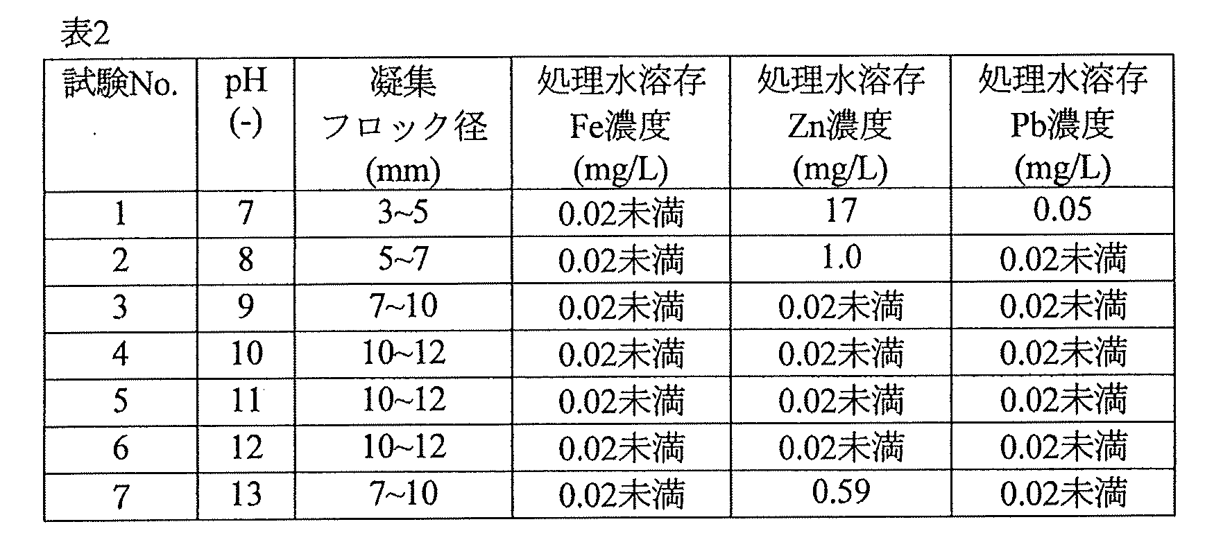
ビーカーに、表1に示した水質の原水(めっき排水)を入れた。このビーカーに、苛性ソーダを添加して、表2に示すようにpHを7に調整した。得られた被処理水に、カチオン系高分子凝集剤(カチオン基比率:3モル%)を、被処理水中の濃度が1mg/Lとなるように添加し、150rpmで2分、急速撹拌を実施した。得られた被処理水に、アニオン系高分子凝集剤(アニオン基比率:17モル%)を、被処理水中の濃度が1mg/Lとなるように添加し、150rpmで1分急速撹拌した。その後、40rpmで5分間緩速撹拌を行った。このとき形成された凝集物の大きさ(凝集フロック径)を測定した。また凝集物の沈静後、処理水(上澄水)を採取し、処理水中の溶存Fe、溶存Zn、溶存Pbの濃度を測定した。これらの測定値を表2に示す。
・試験1
ビーカーに、表1に示した水質の原水(めっき排水)を入れた。このビーカーに、苛性ソーダを添加して、表2に示すようにpHを7に調整した。得られた被処理水に、カチオン系高分子凝集剤(カチオン基比率:3モル%)を、被処理水中の濃度が1mg/Lとなるように添加し、150rpmで2分、急速撹拌を実施した。得られた被処理水に、アニオン系高分子凝集剤(アニオン基比率:17モル%)を、被処理水中の濃度が1mg/Lとなるように添加し、150rpmで1分急速撹拌した。その後、40rpmで5分間緩速撹拌を行った。このとき形成された凝集物の大きさ(凝集フロック径)を測定した。また凝集物の沈静後、処理水(上澄水)を採取し、処理水中の溶存Fe、溶存Zn、溶存Pbの濃度を測定した。これらの測定値を表2に示す。
・試験2~7
各試験において、苛性ソーダの添加により調整するpH値を表2に示すように変更した。それ以外は試験1と同様の試験を行った。得られた測定値を表2に示す。
各試験において、苛性ソーダの添加により調整するpH値を表2に示すように変更した。それ以外は試験1と同様の試験を行った。得られた測定値を表2に示す。
表2に示すように、pH8~13においてはFe、Zn、Pbの全てについて放流基準値(それぞれ10mg/L、2mg/L、0.1mg/L)以下までの除去を確認でき、pH9~12においては全て定量下限値以下まで除去できていた。フロック径は、pH10~12で最も大きく、pH8またpH13のアルカリ域でも、中性域のpH7の場合よりも大きいことが確認された。

〔カチオン基比率を変えた凝集実験(ジャーテスト)〕
・試験8~28
苛性ソーダの添加により調整したpH値を表3に示すように変更した。また、カチオン系高分子凝集剤を変更して、そのカチオン基比率を表3に示すように変更した。それ以外は試験1と同様の試験を行った。ただし、ここでは凝集フロック径のみを測定した。試験8、15及び22の試験条件は、それぞれ前述の試験2、4及び6の試験条件と同一である。また試験14、21及び28においては、カチオン系高分子凝集剤の添加とそれに引き続く急速攪拌を行わず、アニオン系高分子凝集剤(アニオン基比率:17モル%)を被処理水中の濃度が2mg/Lとなるように添加した。
・試験8~28
苛性ソーダの添加により調整したpH値を表3に示すように変更した。また、カチオン系高分子凝集剤を変更して、そのカチオン基比率を表3に示すように変更した。それ以外は試験1と同様の試験を行った。ただし、ここでは凝集フロック径のみを測定した。試験8、15及び22の試験条件は、それぞれ前述の試験2、4及び6の試験条件と同一である。また試験14、21及び28においては、カチオン系高分子凝集剤の添加とそれに引き続く急速攪拌を行わず、アニオン系高分子凝集剤(アニオン基比率:17モル%)を被処理水中の濃度が2mg/Lとなるように添加した。

表3から分かるように、どのpHにおいてもカチオン基比率の低いカチオン系高分子凝集剤、特にカチオン基比率が15モル%以下のカチオン系高分子凝集剤を使用した場合、アニオン高分子凝集剤単独の場合と比べてフロック径の大きな凝集物を形成できた。一方、カチオン基比率35モル%以上のカチオン系高分子凝集剤を用いた試験では、アニオン高分子凝集剤単独の試験と同等の大きさの凝集フロック、もしくはアニオン系高分子凝集剤単独の試験よりもわずかに小さな凝集フロックが形成されていた。
以上から、pH8以上のアルカリ条件下においては、カチオン基比率が30モル%以下、好ましくは15モル%以下、より好ましくは8モル%以下のカチオン系高分子凝集剤と、アニオン系高分子凝集剤を併用することで、粗大で沈降速度の速い凝集フロックを形成できることが期待される。
〔カチオン系高分子凝集剤のカチオン基比率を変えた連続通水試験〕
・実施例1
図1に示す構成を有するアルカリ凝集沈殿装置を用いて連続通水試験を実施し、処理水のSS濃度を測定した。アニオン系高分子凝集剤としては、前述の試験で用いたアニオン基比率17モル%のものを使用した。前述の試験では、表2に示されるとおり、pH9~12においてFe、Zn、Pbを最もよく除去できた。本例では、アルカリの添加量を考慮して、pHを9に調節した。
・実施例1
図1に示す構成を有するアルカリ凝集沈殿装置を用いて連続通水試験を実施し、処理水のSS濃度を測定した。アニオン系高分子凝集剤としては、前述の試験で用いたアニオン基比率17モル%のものを使用した。前述の試験では、表2に示されるとおり、pH9~12においてFe、Zn、Pbを最もよく除去できた。本例では、アルカリの添加量を考慮して、pHを9に調節した。
表1に示す水質の原水を、原水槽10にてpH9に調整し、ポンプPによって一次凝集槽20に送った。一次凝集槽ではカチオン系高分子凝集剤を、被処理水中の濃度が1mg/Lになるように添加し、攪拌翼21で急速撹拌混合することで繊維状の凝集フロックを形成した。カチオン系高分子凝集剤としては、前述の試験で用いたカチオン基比率が3モル%のものを用いた。なお、ブロワBからラインL6を経て供給される空気によって、原水槽10において原水を曝気した。
一次凝集槽20から排出された一次凝集水(ラインL3)に、一次凝集水が沈殿槽30に流入する前に、凝集物の粗大化のためのアニオン系高分子凝集剤を、被処理水中の濃度が1mg/Lになるように添加した。沈殿槽30内では一次凝集水とアニオン系高分子凝集剤が緩速撹拌によって緩やかに混合され、それによって粗大化した凝集物は、緩速撹拌による機械的脱水作用、また転がり運動により、球状のペレットを形成した。
沈殿槽30内では、被処理水が、このペレットによって形成されたスラッジブランケット(ペレットブランケット)Z1と清澄水の層Z2とに分離された。清澄水層Z2から、清澄水をラインL4に抜き出し、処理水を得た。一方、スラッジブランケットZ1を形成する流体は、開口部32から濃縮部33にオーバーフローした。濃縮部33では、沈降によりペレットが濃縮され、濃縮汚泥の層Z3が形成された。濃縮汚泥の層Z3から、濃縮汚泥をラインL5に抜き出し、汚泥として排出した。
このようにして得た処理水のSS濃度を測定した。
<装置仕様>
本例で使用した凝集沈殿装置の仕様を以下に示す。
原水槽10の容量:200L、
一次凝集槽20の容量:10L、
沈殿槽30の容量:2.5L(ブランケット高さ:40cm)、
沈殿槽30の直径:67mm、
沈殿槽30の通水LV:30m/h(106L/h)。
本例で使用した凝集沈殿装置の仕様を以下に示す。
原水槽10の容量:200L、
一次凝集槽20の容量:10L、
沈殿槽30の容量:2.5L(ブランケット高さ:40cm)、
沈殿槽30の直径:67mm、
沈殿槽30の通水LV:30m/h(106L/h)。
・実施例2~7及び比較例1~3
実施例2~7では、カチオン系高分子凝集剤として、カチオン基比率がそれぞれ5、8、15、17、27、30モル%のものを用いた。比較例1~3では、カチオン系高分子凝集剤として、カチオン基比率がそれぞれ35、45、70モル%のものを用いた。なお、カチオン基比率が8、15、35、45及び70モル%のカチオン系高分子凝集剤は、いずれも前述の試験で用いたものと同じである。それ以外は実施例1と同様にして連続通水試験を実施し、処理水のSS濃度を測定した。
実施例2~7では、カチオン系高分子凝集剤として、カチオン基比率がそれぞれ5、8、15、17、27、30モル%のものを用いた。比較例1~3では、カチオン系高分子凝集剤として、カチオン基比率がそれぞれ35、45、70モル%のものを用いた。なお、カチオン基比率が8、15、35、45及び70モル%のカチオン系高分子凝集剤は、いずれも前述の試験で用いたものと同じである。それ以外は実施例1と同様にして連続通水試験を実施し、処理水のSS濃度を測定した。
・比較例4
一次凝集槽20でカチオン系高分子凝集剤を添加しなかった。また、アニオン系高分子凝集剤を、被処理水中の濃度が2mg/Lになるように添加した。これら以外は実施例1と同様にして連続通水試験を実施し、処理水のSS濃度を測定した。
一次凝集槽20でカチオン系高分子凝集剤を添加しなかった。また、アニオン系高分子凝集剤を、被処理水中の濃度が2mg/Lになるように添加した。これら以外は実施例1と同様にして連続通水試験を実施し、処理水のSS濃度を測定した。
上記実施例及び比較例の結果を図2に示す。ただし、この図において、比較例4で得られた処理水のSS濃度は、「アニオンポリマー単独」と注記した破線で示す。比較例1~3では、カチオン系高分子凝集剤とアニオン系高分子凝集剤とをこの順に添加したにもかかわらず、SS濃度が比較例4(カチオン系高分子凝集剤を用いなかった例)よりも高かった。一方、実施例1~7のSS濃度は比較例4よりも低く、カチオン系高分子凝集剤とアニオン系高分子凝集剤とをこの順に添加した効果が得られた。図2から、カチオン基比率が30モル%以下のカチオン系高分子凝集剤を用いれば、このような効果が得られると考えられる。
この結果は、表3に示した試験結果と傾向が同じである。そのため、アルカリ添加によってpH9以外のpH(ただし8以上)に調整した場合においても、カチオン基比率が30モル%以下のカチオン系高分子凝集剤をアニオン系高分子凝集剤の前に添加することによって、アニオン系高分子凝集剤を単独で使用した場合よりも、清澄な処理水を得ることができると想定される。
アルカリ領域で凝集を行う場合、水中には水酸化物イオンが多く存在するが、カチオン系高分子凝集剤のカチオン基比率が高いと、カチオン系高分子凝集剤が水酸基を介して分子内収縮を起こしてしまい架橋構造を取りにくくなる。そのためカチオン基比率の高いカチオン系高分子凝集剤ではカチオン及びアニオン系高分子凝集剤を併用する効果が得られにくく、カチオン基比率の小さいカチオン系高分子凝集剤を用いたほうが粗大で沈降速度の高い凝集物を形成できると考えられる。
〔アニオン系高分子凝集剤のアニオン基比率を変えた連続通水試験〕
・比較例5、実施例8~12
比較例5では、アニオン系高分子凝集剤として、アニオン基比率が4モル%のものを用いた。実施例8~12では、アニオン系高分子凝集剤として、アニオン基比率がそれぞれ10、12、24、32、41モル%のものを用いた。それ以外は実施例1と同様にして連続通水試験を実施し、処理水のSS濃度を測定した。なお、これらの例において用いたカチオン系高分子凝集剤のカチオン基比率は3モル%である。
・比較例5、実施例8~12
比較例5では、アニオン系高分子凝集剤として、アニオン基比率が4モル%のものを用いた。実施例8~12では、アニオン系高分子凝集剤として、アニオン基比率がそれぞれ10、12、24、32、41モル%のものを用いた。それ以外は実施例1と同様にして連続通水試験を実施し、処理水のSS濃度を測定した。なお、これらの例において用いたカチオン系高分子凝集剤のカチオン基比率は3モル%である。
上記の例の結果を、実施例1の結果とともに、図3に示す。アニオン基比率が10モル%以上のアニオン系高分子凝集剤をカチオン系高分子凝集剤と併用した場合に、アニオン系高分子凝集剤を単独で使用した場合よりも、良好な結果を得ることができた。
〔カチオン基比率及びアニオン基比率を変えた連続通水試験〕
・実施例13
カチオン系高分子凝集剤として、前述のカチオン基比率が30モル%のものを用い、アニオン系高分子凝集剤として、前述のアニオン基比率が10モル%のものを用いた。それ以外は実施例1と同様にして連続通水試験を実施し、処理水のSS濃度を測定した。SS濃度は8.0mg/Lであり、アニオン系高分子凝集剤を単独で使用した場合よりも良好であった。
・実施例13
カチオン系高分子凝集剤として、前述のカチオン基比率が30モル%のものを用い、アニオン系高分子凝集剤として、前述のアニオン基比率が10モル%のものを用いた。それ以外は実施例1と同様にして連続通水試験を実施し、処理水のSS濃度を測定した。SS濃度は8.0mg/Lであり、アニオン系高分子凝集剤を単独で使用した場合よりも良好であった。
・実施例14
カチオン系高分子凝集剤として、前述のカチオン基比率が30モル%のものを用い、アニオン系高分子凝集剤として、前述のアニオン基比率が41モル%のものを用いた。それ以外は実施例1と同様にして連続通水試験を実施し、処理水のSS濃度を測定した。SS濃度は5.0mg/Lであり、アニオン系高分子凝集剤を単独で使用した場合よりも良好であった。
カチオン系高分子凝集剤として、前述のカチオン基比率が30モル%のものを用い、アニオン系高分子凝集剤として、前述のアニオン基比率が41モル%のものを用いた。それ以外は実施例1と同様にして連続通水試験を実施し、処理水のSS濃度を測定した。SS濃度は5.0mg/Lであり、アニオン系高分子凝集剤を単独で使用した場合よりも良好であった。
10 原水槽
20 一次凝集槽
21 攪拌翼
30 沈殿槽
31 攪拌翼
32 開口部
33 濃縮部
Z1 スラッジブランケット
Z2 清澄水の層
Z3 濃縮汚泥の層
20 一次凝集槽
21 攪拌翼
30 沈殿槽
31 攪拌翼
32 開口部
33 濃縮部
Z1 スラッジブランケット
Z2 清澄水の層
Z3 濃縮汚泥の層
Claims (7)
- i)金属イオンを含有する被処理水に、アルカリを添加することによって、8以上のpHにおいて金属水酸化物を析出させて懸濁物質を形成する工程と、
ii)工程iから得られた被処理水に、カチオン基比率が30モル%以下のカチオン系高分子凝集剤を添加した後、アニオン基比率が10モル%以上のアニオン系高分子凝集剤を添加することによって、該懸濁物質の凝集物を形成する工程と、
iii)工程iiから得られた被処理水から、スラッジブランケットと清澄水の層とを形成し、該清澄水の層から処理水を得、該スラッジブランケットから汚泥を得る工程と、
を含む水処理方法。 - 前記pH値が13以下である、請求項1に記載の水処理方法。
- 前記pH値が9以上、12以下である、請求項2に記載の水処理方法。
- 前記カチオン系高分子凝集剤のカチオン基比率が15モル%以下である、請求項1~3のいずれか一項に記載の水処理方法。
- 前記カチオン系高分子凝集剤のカチオン基比率が8モル%以下である、請求項4に記載の水処理方法。
- スラッジブランケットを撹拌することにより、前記凝集物の造粒を行う工程を有する、請求項1~5のいずれか一項に記載の水処理方法。
- 金属イオンを含有する被処理水にアルカリを添加する、アルカリ添加手段と、
アルカリ添加手段より下流側に設けられた、被処理水にカチオン基比率が30モル%以下のカチオン系高分子凝集剤を添加する、カチオン系高分子凝集剤添加手段と、
カチオン系高分子凝集剤添加手段より下流側に設けられた、被処理水にアニオン基比率が10モル%以上のアニオン系高分子凝集剤を添加するアニオン系高分子凝集剤添加手段と、
アニオン系高分子凝集剤添加手段より下流側に設けられた、被処理水からスラッジブランケットと清澄水の層とを形成し、該清澄水の層から処理水を得、該スラッジブランケットから汚泥を得る、スラッジブランケット型沈殿槽と、
を含む水処理装置。
Applications Claiming Priority (2)
| Application Number | Priority Date | Filing Date | Title |
|---|---|---|---|
| JP2017249307A JP7117101B2 (ja) | 2017-12-26 | 2017-12-26 | 水処理方法及び装置 |
| JP2017-249307 | 2017-12-26 |
Publications (1)
| Publication Number | Publication Date |
|---|---|
| WO2019130635A1 true WO2019130635A1 (ja) | 2019-07-04 |
Family
ID=67066891
Family Applications (1)
| Application Number | Title | Priority Date | Filing Date |
|---|---|---|---|
| PCT/JP2018/028680 Ceased WO2019130635A1 (ja) | 2017-12-26 | 2018-07-31 | 水処理方法及び装置 |
Country Status (2)
| Country | Link |
|---|---|
| JP (1) | JP7117101B2 (ja) |
| WO (1) | WO2019130635A1 (ja) |
Families Citing this family (1)
| Publication number | Priority date | Publication date | Assignee | Title |
|---|---|---|---|---|
| KR102942841B1 (ko) * | 2023-03-09 | 2026-03-24 | 에스엔에프 그룹 | 제지폐수 및 폐수처리공정 중의 콜로이드성 toc원 처리기술 |
Citations (7)
| Publication number | Priority date | Publication date | Assignee | Title |
|---|---|---|---|---|
| JPH07973A (ja) * | 1993-03-17 | 1995-01-06 | Westinghouse Electric Corp <We> | 重金属及び放射性汚染要因物の除去方法 |
| JPH07275606A (ja) * | 1994-04-11 | 1995-10-24 | Nippon Steel Corp | 固液分離装置 |
| JP2002113473A (ja) * | 2000-10-06 | 2002-04-16 | National Institute Of Advanced Industrial & Technology | 有害金属イオンの除去方法及び除去剤 |
| JP2011139997A (ja) * | 2010-01-07 | 2011-07-21 | Daiyanitorikkusu Kk | 廃水の凝集処理方法 |
| JP2012091079A (ja) * | 2010-10-25 | 2012-05-17 | Daiyanitorikkusu Kk | 有機凝結剤 |
| WO2014038537A1 (ja) * | 2012-09-10 | 2014-03-13 | 栗田工業株式会社 | 水処理方法及び装置 |
| JP2015066546A (ja) * | 2013-10-01 | 2015-04-13 | 栗田工業株式会社 | 無機イオン含有排水の処理方法及び装置 |
Family Cites Families (1)
| Publication number | Priority date | Publication date | Assignee | Title |
|---|---|---|---|---|
| JP6589563B2 (ja) * | 2015-11-02 | 2019-10-16 | 栗田工業株式会社 | 水処理方法及び水処理装置 |
-
2017
- 2017-12-26 JP JP2017249307A patent/JP7117101B2/ja active Active
-
2018
- 2018-07-31 WO PCT/JP2018/028680 patent/WO2019130635A1/ja not_active Ceased
Patent Citations (7)
| Publication number | Priority date | Publication date | Assignee | Title |
|---|---|---|---|---|
| JPH07973A (ja) * | 1993-03-17 | 1995-01-06 | Westinghouse Electric Corp <We> | 重金属及び放射性汚染要因物の除去方法 |
| JPH07275606A (ja) * | 1994-04-11 | 1995-10-24 | Nippon Steel Corp | 固液分離装置 |
| JP2002113473A (ja) * | 2000-10-06 | 2002-04-16 | National Institute Of Advanced Industrial & Technology | 有害金属イオンの除去方法及び除去剤 |
| JP2011139997A (ja) * | 2010-01-07 | 2011-07-21 | Daiyanitorikkusu Kk | 廃水の凝集処理方法 |
| JP2012091079A (ja) * | 2010-10-25 | 2012-05-17 | Daiyanitorikkusu Kk | 有機凝結剤 |
| WO2014038537A1 (ja) * | 2012-09-10 | 2014-03-13 | 栗田工業株式会社 | 水処理方法及び装置 |
| JP2015066546A (ja) * | 2013-10-01 | 2015-04-13 | 栗田工業株式会社 | 無機イオン含有排水の処理方法及び装置 |
Also Published As
| Publication number | Publication date |
|---|---|
| JP7117101B2 (ja) | 2022-08-12 |
| JP2019111513A (ja) | 2019-07-11 |
Similar Documents
| Publication | Publication Date | Title |
|---|---|---|
| JP5143762B2 (ja) | 凝集沈殿装置 | |
| JP5364298B2 (ja) | 分散剤含有水の処理方法 | |
| EP3221269B1 (en) | Improved ballasted clarification method | |
| JP6793014B2 (ja) | 排水処理方法及び排水処理装置 | |
| JP5256261B2 (ja) | 有機性汚泥の脱水方法及び装置 | |
| JP2022165279A (ja) | 凝集膜ろ過処理方法 | |
| JP5509927B2 (ja) | 金属含有水の処理方法及び金属含有水の処理装置 | |
| JP2009066508A (ja) | 有機物含有水の凝集処理方法 | |
| JP4661665B2 (ja) | イオン含有排水の凝集沈澱処理方法 | |
| JP2013078730A (ja) | 凝集沈殿処理方法および凝集沈殿処理装置 | |
| JP4272122B2 (ja) | 凝集沈殿水処理方法及び装置 | |
| JP7083274B2 (ja) | 水処理方法および水処理装置 | |
| JP2000317220A (ja) | 凝集沈澱装置 | |
| JP2018153729A (ja) | 水処理剤、水処理方法及び水処理装置 | |
| WO2019077835A1 (ja) | 凝集沈殿装置及び凝集沈殿処理方法 | |
| JP7117101B2 (ja) | 水処理方法及び装置 | |
| WO2019208532A1 (ja) | 水処理方法及び水処理装置 | |
| JP2021186793A (ja) | 浄水処理方法及び浄水処理装置 | |
| JP2861371B2 (ja) | 排水処理法 | |
| JPH03137987A (ja) | 排水処理法 | |
| JP2003145168A (ja) | 懸濁水の凝集固液分離方法及び装置 | |
| JP5693992B2 (ja) | 多種金属イオン含有排水からの溶存鉄の回収方法 | |
| JP5874359B2 (ja) | 凝集処理方法 | |
| JP2005007246A (ja) | 有機性廃水の処理方法 | |
| JP7142540B2 (ja) | 浄水処理方法及び浄水処理装置 |
Legal Events
| Date | Code | Title | Description |
|---|---|---|---|
| 121 | Ep: the epo has been informed by wipo that ep was designated in this application |
Ref document number: 18896629 Country of ref document: EP Kind code of ref document: A1 |
|
| NENP | Non-entry into the national phase |
Ref country code: DE |
|
| 122 | Ep: pct application non-entry in european phase |
Ref document number: 18896629 Country of ref document: EP Kind code of ref document: A1 |