WO2019130578A1 - 脱硝触媒の劣化評価方法 - Google Patents
脱硝触媒の劣化評価方法 Download PDFInfo
- Publication number
- WO2019130578A1 WO2019130578A1 PCT/JP2017/047344 JP2017047344W WO2019130578A1 WO 2019130578 A1 WO2019130578 A1 WO 2019130578A1 JP 2017047344 W JP2017047344 W JP 2017047344W WO 2019130578 A1 WO2019130578 A1 WO 2019130578A1
- Authority
- WO
- WIPO (PCT)
- Prior art keywords
- nox removal
- catalyst
- average thickness
- deterioration
- layer
- Prior art date
- Legal status (The legal status is an assumption and is not a legal conclusion. Google has not performed a legal analysis and makes no representation as to the accuracy of the status listed.)
- Ceased
Links
Images



Classifications
-
- B—PERFORMING OPERATIONS; TRANSPORTING
- B01—PHYSICAL OR CHEMICAL PROCESSES OR APPARATUS IN GENERAL
- B01D—SEPARATION
- B01D53/00—Separation of gases or vapours; Recovering vapours of volatile solvents from gases; Chemical or biological purification of waste gases, e.g. engine exhaust gases, smoke, fumes, flue gases, aerosols
- B01D53/34—Chemical or biological purification of waste gases
- B01D53/74—General processes for purification of waste gases; Apparatus or devices specially adapted therefor
- B01D53/86—Catalytic processes
-
- G—PHYSICS
- G01—MEASURING; TESTING
- G01N—INVESTIGATING OR ANALYSING MATERIALS BY DETERMINING THEIR CHEMICAL OR PHYSICAL PROPERTIES
- G01N23/00—Investigating or analysing materials by the use of wave or particle radiation, e.g. X-rays or neutrons, not covered by groups G01N3/00 – G01N17/00, G01N21/00 or G01N22/00
- G01N23/22—Investigating or analysing materials by the use of wave or particle radiation, e.g. X-rays or neutrons, not covered by groups G01N3/00 – G01N17/00, G01N21/00 or G01N22/00 by measuring secondary emission from the material
- G01N23/225—Investigating or analysing materials by the use of wave or particle radiation, e.g. X-rays or neutrons, not covered by groups G01N3/00 – G01N17/00, G01N21/00 or G01N22/00 by measuring secondary emission from the material using electron or ion
- G01N23/2251—Investigating or analysing materials by the use of wave or particle radiation, e.g. X-rays or neutrons, not covered by groups G01N3/00 – G01N17/00, G01N21/00 or G01N22/00 by measuring secondary emission from the material using electron or ion using incident electron beams, e.g. scanning electron microscopy [SEM]
-
- G—PHYSICS
- G01—MEASURING; TESTING
- G01N—INVESTIGATING OR ANALYSING MATERIALS BY DETERMINING THEIR CHEMICAL OR PHYSICAL PROPERTIES
- G01N31/00—Investigating or analysing non-biological materials by the use of the chemical methods specified in the subgroup; Apparatus specially adapted for such methods
- G01N31/10—Investigating or analysing non-biological materials by the use of the chemical methods specified in the subgroup; Apparatus specially adapted for such methods using catalysis
Definitions
- the present invention relates to a method for evaluating deterioration of a NOx removal catalyst.
- a NOx removal system is installed to reduce and decompose nitrogen oxides.
- the denitrification apparatus is filled with a denitrification catalyst, and coexistence of ammonia (gas) causes a reduction reaction to occur at a high temperature.
- this NOx removal catalyst operates efficiently in a high temperature atmosphere of 300 ° C. to 400 ° C., it is necessary to remove NOx from the exhaust gas containing a large amount of soot and dust immediately after combustion in the boiler. Therefore, coal ash is deposited on the catalyst surface over time by long-term use, and the activity of the NOx removal catalyst is reduced by covering the entire catalyst surface.
- DeNOx catalysts with reduced activity need to be replaced with fresh catalysts or subjected to regeneration treatment to maintain the performance of the NOx removal system.
- Patent Document 1 describes a method of replacing a NOx removal catalyst in a flue gas NOx removal apparatus in which a NOx removal catalyst is charged in a plurality of stages, and a catalyst removal step of removing the first NOx removal catalyst positioned on the most upstream side. And a catalyst transfer step of sequentially moving all the denitrification catalysts from the second stage onward to the first stage upstream, and replenishing a new denitration catalyst to the most downstream stage which has been emptied by the catalyst transfer step. And a catalyst replenishment step is disclosed.
- an object of the present invention is to evaluate deterioration of a NOx removal catalyst disposed in a NOx removal device installed downstream of a combustion boiler with higher accuracy than in the past.
- the present invention has the following configuration.
- (1) A method for evaluating deterioration of a NOx removal catalyst disposed in a NOx removal apparatus for removing nitrogen oxides contained in exhaust gas generated by combustion of coal, in a thermal power generation system using coal, which comprises the middle layer of the NOx removal catalyst
- the average thickness of the coating layer containing particles having a particle diameter of 2 ⁇ m or less deposited on the surface of the collected measurement sample is measured, and the denitration rate is predicted based on the correlation between the average thickness and the denitration rate.
- Deterioration evaluation method for evaluating the deterioration of the NOx removal catalyst is analyzed.
- the area of the covering layer included in the cross-sectional image of the measurement sample is divided by the width of the cross-sectional image to calculate the average thickness.
- the average thickness when the average thickness is measured, the area of the void in the covering layer is subtracted from the area of the covering layer included in the cross-sectional image, and the area is divided by the width of the image. By doing this, the average thickness may be calculated.
- a plurality of images may be used as the cross-sectional image.
- a microscopic image with a magnification of 5000 to 10000 may be used as the cross-sectional image.
- deterioration evaluation method of a NOx removal catalyst in a thermal power generation system using coal of the present invention since deterioration of the NOx removal catalyst can be evaluated with higher accuracy than before, appropriate management such as replacement or regeneration of the NOx removal catalyst can be performed. Is possible.
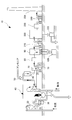
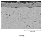
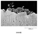
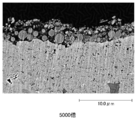
- FIG. 1 It is a schematic block diagram of the pulverized coal combustion facility in the coal thermal power plant showing one embodiment of the present invention. It is an enlarged view of the NOx removal apparatus vicinity of FIG. It is a scanning electron microscope (SEM) image of the cross section of the NOx removal catalyst in the entrance vicinity (x 5000 times). It is a scanning electron microscope (SEM) image of the cross section of the NOx removal catalyst in the entrance vicinity (x 5000 times). It is a scanning electron microscope (SEM) image of the cross section of the NOx removal catalyst in the entrance vicinity (x 20000 times). It is a scanning electron microscope (SEM) image of the cross section of the NOx removal catalyst in the entrance vicinity (x 5000 times).
- SEM scanning electron microscope
- FIG. 1 shows the configuration of a coal-fired power plant 10 for carrying out the deterioration evaluation method of the present embodiment.
- the coal thermal power plant 10 is provided in a coal bunker 20, a coal feeder 25, a pulverized coal machine 30, a combustion boiler 40, an exhaust passage 50 provided on the downstream side of the combustion boiler 40, and the exhaust passage 50.
- the coal bunker 20 stores coal supplied from a coal silo (not shown) by a coal transportation facility.
- the coal feeder 25 supplies the coal supplied from the coal bunker 20 to the pulverized coal machine 30 at a predetermined supply speed.
- a roller mill, a tube mill, a ball mill, a beater mill, an impeller mill or the like is used as the pulverized coal machine 30.
- the combustion boiler 40 burns the pulverized coal supplied from the pulverized coal machine 30 together with the forcibly supplied air. Further, combustion air is fed to the combustion boiler 40 from the push-in ventilator 75.
- the combustion of the pulverized coal produces coal ash such as clinker ash and fly ash, and also produces an exhaust gas.
- the main components of coal ash are 40 to 70% of silica (SiO 2 ) and 20 to 40% of alumina (Al 2 O 3 ), and iron oxide (Fe 2 O 3 ), calcium (CaO), potassium (K) and others. 2 O), magnesium (MgO), sodium (Na 2 O), etc. are contained in a small amount.
- the exhaust passage 50 is disposed downstream of the combustion boiler 40 and distributes the exhaust gas generated by the combustion boiler 40 and the generated coal ash.
- the NOx removal device 60, the air preheater 70, the gas heater (for heat recovery) 80, the electrostatic precipitator 90, the induction ventilator 210, the desulfurizer 220, the gas heater (for reheating ), Desulfurizing ventilator 240, and chimney 250 are arranged in this order.
- the NOx removal device 60 removes nitrogen oxides in the exhaust gas.
- the denitrification apparatus 60 injects ammonia gas as a reducing agent into the exhaust gas at a relatively high temperature (300 ° C. to 400 ° C.), and acts as a denitrification catalyst to combine nitrogen oxides in the exhaust gas with harmless nitrogen.
- the nitrogen oxides in the exhaust gas are removed by so-called dry ammonia catalytic reduction which decomposes into steam.
- the denitrification apparatus 60 comprises a denitrification reactor 61, multiple stages of denitrification catalyst layers 62, 62, 62 disposed inside the denitrification reactor 61, and an upstream side of the denitrification catalyst layer 62.
- a rectifying layer 63 is disposed, a rectifying plate 64 disposed in the vicinity of the inlet of the denitration reactor 61, and an ammonia injection unit 65 disposed on the upstream side of the denitration reactor 61.
- the denitrification reactor 61 is a place for denitrification reaction in the denitrification apparatus 60.
- the NOx removal catalyst layer 62 is disposed inside the NOx removal reactor 61 at a plurality of stages (three stages in this embodiment) at predetermined intervals along the flow path of the exhaust gas.
- the NOx removal catalyst layer 62 is configured to include a plurality of catalyst bodies (not shown) as NOx removal catalysts.
- the shape of the catalyst include particulate catalysts, plate catalysts, lattice catalysts and the like.
- the exhaust gas contains a large amount of dust, so it has excellent dust resistance and low pressure loss, and is a parallel flow type lattice catalyst in which the catalyst surface is disposed parallel to the gas flow Or a honeycomb catalyst) or a plate-like catalyst is suitably used.
- the honeycomb catalyst is more preferably used because of its excellent dust resistance and low pressure loss.
- the honeycomb catalyst is formed in a long shape (rectangular shape) in which a plurality of exhaust gas flow holes extending in the longitudinal direction are formed. Then, the plurality of honeycomb catalysts are disposed such that the exhaust gas flow holes are along the flow path of the exhaust gas.
- the honeycomb catalyst for example, one having a rectangular shape of 150 mm ⁇ 150 mm ⁇ 860 mm and 400 (20 ⁇ 20) exhaust gas flow holes of 6 mm ⁇ 6 mm openings is used. The opening is adjusted in accordance with the flow rate of the exhaust gas to prevent clogging and abrasion of the honeycomb catalyst due to dust.
- 9000 to 10000 honeycomb catalysts are installed in the one-layer NOx removal catalyst layer 62.
- the honeycomb catalyst is formed by extruding a catalyst active component such as vanadium pentoxide or tungsten oxide after mixing it with titanium oxide or zirconium oxide.
- the rectifying layer 63 is disposed upstream of the NOx removal catalyst layer 62.
- the rectifying layer 63 is formed of a metal member or the like having a plurality of openings formed in a lattice shape, and divides the flow path of the exhaust gas in the denitrification reactor 61.
- the rectifying layer 63 rectifies the exhaust gas flowing through the exhaust passage 50 and introduced into the NOx removal reactor 61 and uniformly guides the exhaust gas to the NOx removal catalyst layer 62.
- the rectifying plate 64 is disposed upstream of the rectifying layer 63 in the vicinity of the inlet of the NOx removal reactor 61. More specifically, the straightening vane 64 is disposed at a bent portion in the inner wall of the denitration reactor 61 or the exhaust passage 50, and protrudes from the inner wall toward the inner surface.
- the baffle plate 64 regulates the flow of the exhaust gas at the bent portion of the exhaust passage 50 or the denitrification reactor 61.
- the partial flow introduced to the NOx removal catalyst layer 62 is reduced, and clogging and abrasion of the NOx removal catalyst layer 62 by dust are prevented.
- the ammonia injection unit 65 is disposed on the upstream side of the NOx removal reactor 61 and injects ammonia into the exhaust passage 50.
- ammonia is injected into the high temperature exhaust gas (300 ° C. to 400 ° C.) flowing through the exhaust passage 50 in the ammonia injection unit 65.
- the exhaust gas into which the ammonia is injected is rectified by the rectifying plate 64 and the rectifying layer 63 and introduced into the NOx removal catalyst layer 62.
- the above method is called dry ammonia catalytic reduction.
- the denitration rate will be improved, but the unreacted NH 3 (hereinafter referred to as leaked NH 3 ) discharged will increase.
- leaked NH 3 it reacts with SO 3 in the exhaust gas to form acidic ammonium sulfate (NH 4 HSO 4 ), and this acidic ammonium sulfate promotes adhesion of dust contained in the exhaust gas and an air preheater installed at a later stage Clogging of the elements of the Therefore, the performance management of the catalyst is performed so that the leak NH 3 becomes equal to or less than a predetermined value.
- Purification rate i.e. denitrification efficiency of the NO x is calculated based on the inlet side and the outlet side of the NO x concentration of the denitration catalyst.
- the denitrification rate of the entire denitrification apparatus is about 80 to 90% immediately after the start of use, but since the denitrification catalyst is deteriorated by the use and the denitrification rate decreases, it is necessary to appropriately replace the denitrification catalyst, regenerate it.
- the progress of the deterioration is not uniform in each catalyst layer, and it is the first catalyst layer through which the exhaust gas first passes that is the most rapidly progressed. Therefore, it is uneconomical to replace all denitration catalysts as the overall denitration rate decreases, so for example, the deterioration state is evaluated for each denitration catalyst in each catalyst layer, and the catalyst layer in progress is replaced Methods are taken, such as
- the causes of deterioration of the NOx removal catalyst have been considered to be thermal deterioration such as sintering, chemical deterioration due to poisoning of catalyst components, and physical deterioration due to coal ash covering the catalyst surface.
- thermal deterioration such as sintering, chemical deterioration due to poisoning of catalyst components, and physical deterioration due to coal ash covering the catalyst surface.
- the NOx removal rate of the NOx removal catalyst was calculated from data such as NOx concentration on the inlet side and the outlet side of the NOx removal catalyst at daily management and inspection.
- the inventors of the present invention have a particle size much smaller than the range of about several tens of ⁇ m to 100 ⁇ m, which is the average particle size of coal ash.
- Deposits derived from coal ash (1-2 ⁇ m or less, more specifically about several tens of nm) coat the surface of the NOx removal catalyst to form a coating layer, thereby causing clogging of the NOx removal catalyst Found out.
- Such small particle size coal ash has not been considered to be the cause of the deterioration of the NOx removal catalyst up to now because it is low in content.
- the deterioration state of the NOx removal catalyst can be evaluated by measuring the thickness of the coating layer that covers the surface of the NOx removal catalyst. Therefore, the deterioration state of the NOx removal catalyst can be evaluated more accurately than before, and prediction etc. of the replacement timing of the NOx removal catalyst can be performed more accurately. Therefore, management such as replacement or regeneration of the deteriorated NOx removal catalyst can be more appropriately performed.
- the air preheater 70 is disposed downstream of the NOx removal device 60 in the exhaust passage 50.
- the air preheater 70 exchanges heat between the exhaust gas having passed through the denitration apparatus 60 and the combustion air to cool the exhaust gas and heat the combustion air.
- the heated combustion air is supplied to the combustion boiler 40 by the push-in ventilator 75.
- the gas heater 80 is disposed downstream of the air preheater 70 in the exhaust passage 50.
- the gas heater 80 is supplied with the exhaust gas heat-recovered in the air preheater 70.
- the gas heater 80 further recovers heat from the exhaust gas.
- the electrostatic precipitator 90 is disposed downstream of the gas heater 80 in the exhaust passage 50.
- the exhaust gas heat-recovered by the gas heater 80 is supplied to the electrostatic precipitator 90.
- the electrostatic precipitator 90 is a device that collects coal ash (fly ash) in the exhaust gas by applying a voltage to the electrodes. Fly ash collected by the electrostatic precipitator 90 is collected by the fly ash collection device 120.
- the induction ventilator 210 is disposed downstream of the electrostatic precipitator 90 in the exhaust passage 50.
- the induction ventilator 210 takes in the exhaust gas from which the fly ash has been removed by the electrostatic precipitator 90 from the primary side and sends it out to the secondary side.
- the desulfurization device 220 is disposed downstream of the induction ventilator 210 in the exhaust passage 50.
- the desulfurization device 220 is supplied with the exhaust gas sent from the induction ventilator 210.
- the desulfurization apparatus 220 absorbs the sulfur oxides contained in the exhaust gas into the mixed liquid by spraying the mixed liquid of limestone and water to the exhaust gas, generates a desulfurized gypsum slurry, and dehydrates the desulfurized gypsum slurry. To produce desulfurization gypsum.
- the desulfurized gypsum generated in the desulfurization device 220 is recovered by the desulfurized gypsum recovery device 222 connected to this device.
- the gas heater 230 is disposed downstream of the desulfurizer 220 in the exhaust passage 50.
- the gas heater 230 is supplied with the exhaust gas from which the sulfur oxides have been removed by the desulfurizer 220.
- the gas heater 230 heats the exhaust gas.
- the gas heater 80 and the gas heater 230 are provided between the exhaust gas flowing between the air preheater 70 and the electrostatic precipitator 90 in the exhaust passage 50 and the exhaust gas flowing between the desulfurization apparatus 220 and the desulfurization ventilator 240. It may constitute as a gas heater which performs heat exchange.
- the desulfurization ventilator 240 is disposed downstream of the gas heater 230 in the exhaust passage 50.
- the desulfurization ventilator 240 takes in the exhaust gas heated by the gas heater 230 from the primary side and sends it to the secondary side.
- the chimney 250 is disposed downstream of the desulfurization ventilator 240 in the exhaust passage 50.
- the exhaust gas heated by the gas heater 230 is introduced into the chimney 250.
- the chimney 250 emits exhaust gas.
- FIG. 3 shows 11 years from the start of use of the above-mentioned honeycomb catalyst (having a rectangular shape of short 150 mm ⁇ 150 mm ⁇ long 860 mm and 400 (20 ⁇ 20) exhaust gas flow holes with 6 mm ⁇ 6 mm openings) formed. It is a scanning electron microscope (SEM) image (x 5000 times) in the vicinity of the catalyst surface of the cross section along the transversal direction in the vicinity of the entrance of a degree NOx removal catalyst. Further, FIG.
- SEM scanning electron microscope
- FIG. 4 is a scanning electron microscope (SEM) image ( ⁇ 5000) near the catalyst surface of the cross section along the short direction in the vicinity of the middle of the denitration catalyst for about one year from the start of use for the same kind of honeycomb catalyst. Times).
- FIG. 5 is a scanning electron microscope (SEM) image (x 20000 times) in the vicinity of the catalyst surface of the cross section along the transverse direction in the vicinity of the middle of the NOx removal catalyst for about one year from the start of use.
- FIG. 6 is a scanning electron microscope (SEM) image ( ⁇ 5000 ⁇ ) in the vicinity of the catalyst surface of the cross section along the lateral direction in the vicinity of the middle of the denitrification catalyst for about 2 years from the start of use.
- a portion surrounded by a solid line is a coating layer including particles having a particle diameter of 2 ⁇ m or less.
- the average thickness is calculated by dividing the area of the part surrounded by the solid line by the width of the covering layer, that is, the width of the image in FIG.
- the width of the visual field displayed in the image is 25 ⁇ m, that is, the magnification of 5,000 to 10,000.
- the average thickness is calculated by using a plurality of approximately doubled microscope images. If, as in FIG. 5, a microscopic image with a magnification of about 20,000 is used, it can be seen that the coating layer, which is only locally deposited, is actually deposited over the entire surface of the catalyst. This is because the average thickness is to be calculated as a premise.
- the covering layer has many voids
- the area of the covering layer in direct contact with the surface of the NOx removal catalyst is measured, and the measured value is divided by the width of the image to obtain the average thickness. Calculate Thereby, even if the apparent average thickness of the covering layer is large, when the number of voids is large, it can be reflected that the reduction of the NOx removal rate does not occur.
- a microscope image of another location with only a small number of voids may be used.
- FIG. 7 shows the change in the thickness of the coating layer (silica layer) in the gas flow direction of the NOx removal catalyst having a service life of approximately 11 years and a NOx removal rate of approximately 63%. From 0 mm (inlet) to about 100 mm in catalyst length, the thickness of the covering layer drops with a high slope, and after exceeding about 100 mm, the thickness of the covering layer drops with a gentle slope.
- the measurement sample near the inlet of the NOx removal catalyst is taken as the measurement sample, the sampling point
- the measurement value of the average thickness of the coating layer is stabilized by collecting the measurement sample of the intermediate layer of the NOx removal catalyst.
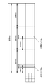
- FIG. 8 shows the collection point of the measurement sample for calculating the average thickness of the coating layer.
- the denitrification catalyst A to denitrification catalyst E each having a longitudinal length of 860 mm shown in Table 1 below are divided into three equally in the inlet layer / intermediate layer / outlet in the longitudinal direction, and the exhaust gas inlet for the inlet layer
- the measurement sample was taken from the range of 50 mm to 80 mm from the side and from the range of 387 mm to 417 mm from the exhaust gas inlet side for the intermediate layer, and the average thickness of the coating layer was calculated.
- the NOx removal catalyst A is a new NOx removal catalyst.
- the denitration catalyst B is a denitration catalyst which was loaded with a fresh catalyst into a denitration apparatus and one year has passed since the loading.
- the NOx removal catalysts C and D are new NOx removal catalysts loaded into a NOx removal device and 1.5 years after loading.
- the NOx removal catalyst E is a used NOx removal catalyst that has been disposed of.
- the NOx removal efficiency was measured for each of the NOx removal catalyst A to the NOx removal catalyst E described above, for example, by the measurement method described in JP-A-2011-161137. More specifically, the gas components (mass flow controller (MFC) etc.) create gas components under the same conditions as the exhaust gas discharged from the power plant boiler (except dust), and use vaporizers and preheaters. The temperature was raised to the same temperature as the exhaust gas, and the temperature in the reaction tube was maintained in the reactor. Then, the temperature, the gas + NH 3 where the respective gas concentration in actual same conditions is passed through the catalyst, measuring the NOx before and after the catalyst, measured such NOx removal efficiency ((inlet NOx- outlet NOx) / inlet NOx ⁇ 100) did.
- MFC mass flow controller
- Table 1 shows the relationship between the NOx removal rate, the time of use, and the average thickness of the coating layer of the measurement samples collected from the inlet layer and the intermediate layer of each NOx removal catalyst.
- the denitrification rate generally decreased while the thickness of the coating layer generally increased as the use time passed. Also, comparing the thickness of the covering layer of the inlet layer with the thickness of the covering layer of the intermediate layer, the thickness of the covering layer of the inlet layer is about 1.3 times to 2 times the thickness of the covering layer of the intermediate layer. It is twice as thick.
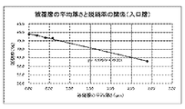
- FIG. 9 is a graph showing the relationship between the average thickness of the coating layer at the inlet layer in Table 1 and the NOx removal rate.
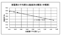
- FIG. 10 is a graph showing the relationship between the average thickness of the covering layer in the intermediate layer in Table 1 and the NOx removal rate.
- the average thickness of the covering layer in the inlet layer and the average thickness of the covering layer in the intermediate layer since there is a high correlation between the average thickness of the covering layer in the inlet layer and the average thickness of the covering layer in the intermediate layer, the average thickness of the covering layer in the inlet layer and the denitrification The deterioration of the NOx removal catalyst is evaluated with high accuracy even if the deterioration of the NOx removal catalyst is evaluated by using the correlation between the average thickness of the coating layer in the intermediate layer and the NOx removal efficiency, instead of using the correlation with the NOx conversion ratio. It turned out that degradation can be evaluated. Furthermore, as described above, when the measurement sample is collected by the inlet layer of the denitrification catalyst, the measured value of the average thickness of the coating layer may be largely deviated only when the sampling point is slightly shifted back and forth.
- the variation in the measured value is reduced. Therefore, the deterioration of the NOx removal catalyst can be more accurately evaluated by predicting the NOx removal rate using the measurement sample collected from the intermediate layer of the NOx removal catalyst.
- the average thickness of the coating layer containing particles having a particle diameter of 2 ⁇ m or less deposited on the surface of the measurement sample collected from the intermediate layer of the denitrification catalyst is measured.
- the deterioration of the NOx removal catalyst is evaluated by predicting the NOx removal rate based on the correlation with the NOx removal rate. Therefore, by collecting the measurement sample from the intermediate layer of the NOx removal catalyst, deterioration of the NOx removal catalyst can be evaluated with higher accuracy than in the past.
- the area of the coating layer included in the cross-sectional image of the measurement sample is divided by the width of the cross-sectional image to calculate the average thickness. Do. Therefore, the deterioration of the NOx removal catalyst can be evaluated with higher accuracy than before by excluding local unevenness of the covering layer.
- the deterioration of the NOx removal catalyst can be evaluated with higher accuracy than before by minimizing the error of the average thickness caused by the void portion.
- the deterioration evaluation method of the NOx removal catalyst when measuring the average thickness, a plurality of images are used as cross-sectional images of the measurement sample. Therefore, the deterioration of the NOx removal catalyst can be evaluated with higher accuracy than before by measuring the average thickness from a plurality of images.
Landscapes
- Chemical & Material Sciences (AREA)
- Health & Medical Sciences (AREA)
- Analytical Chemistry (AREA)
- Engineering & Computer Science (AREA)
- Life Sciences & Earth Sciences (AREA)
- General Health & Medical Sciences (AREA)
- Chemical Kinetics & Catalysis (AREA)
- Biochemistry (AREA)
- Environmental & Geological Engineering (AREA)
- General Physics & Mathematics (AREA)
- Immunology (AREA)
- Pathology (AREA)
- Physics & Mathematics (AREA)
- Molecular Biology (AREA)
- Biomedical Technology (AREA)
- General Chemical & Material Sciences (AREA)
- Oil, Petroleum & Natural Gas (AREA)
- Exhaust Gas Treatment By Means Of Catalyst (AREA)
- Analysing Materials By The Use Of Radiation (AREA)
Abstract
石炭火力発電システムにおいて、燃焼ボイラの下流に設置される脱硝装置内に配置される脱硝触媒の劣化を評価すること。 石炭を用いる火力発電システムにおいて、石炭の燃焼によって生じる排ガスに含まれる窒素酸化物を除去する脱硝装置内に配置される脱硝触媒の劣化評価方法であって、前記脱硝触媒の中間層から採取した測定サンプルの表面に堆積している、粒径2μm以下の粒子を含む被覆層の平均厚さを測定し、平均厚さと脱硝率との相関関係に基づいて、脱硝率を予測し、予測された脱硝率を用いて脱硝触媒の劣化を評価する。
Description
本発明は、脱硝触媒の劣化評価方法に関する。
石炭火力発電所では、石炭燃焼に伴い窒素酸化物が発生するが、大気汚染防止法等の規制により、その排出は一定水準以下に抑えて排出することとなっている。そこで発電所では、窒素酸化物を還元分解するために脱硝装置が設置されている。この脱硝装置には、脱硝触媒が充填されており、アンモニア(ガス)を共存させることで、高温化で還元反応を発現している。
この脱硝触媒は、300℃~400℃の高温雰囲気下で効率的に作動するため、ボイラで燃焼した直後の、煤塵が非常に多く含まれた排ガスを脱硝する必要がある。そのため、長期間の利用により、石炭灰が経時的に触媒表面へ堆積し、触媒表面全体を覆うことで、脱硝触媒の活性が低下する。
活性が低下した脱硝触媒は、脱硝装置の性能を維持するため、新品の触媒に取り替えられたり、再生処理を行ったりする必要がある。
例えば、下記の特許文献1には、脱硝触媒が複数段充填された排煙脱硝装置の脱硝触媒の交換方法であって、最上流側に位置する第1段目の脱硝触媒を取り出す触媒取出し工程と、第2段目以降の全ての脱硝触媒を順次、1段上流側に移動させる触媒移動工程と、前記触媒移動工程により移動して空となった最下流段に新たな脱硝触媒を補充する触媒補充工程と、を含む脱硝触媒の交換方法が開示されている。
しかし、従来技術において、新品の触媒への取り替えや再生方法の検討にあたり、触媒サンプルを採取し、触媒性能試験等を実施しているが、触媒性能試験として従来実施してきた脱硝率等の測定では、触媒性能の評価結果にバラつきが発生する可能性が高い。
従って、本発明は、燃焼ボイラの下流に設置される脱硝装置内に配置される脱硝触媒の劣化を、従来よりも高い精度で評価することを目的とする。
前記目的を達成するため、本発明は、次に記載する構成を備えている。
(1)石炭を用いる火力発電システムにおいて、石炭の燃焼によって生じる排ガスに含まれる窒素酸化物を除去する脱硝装置内に配置される脱硝触媒の劣化評価方法であって、前記脱硝触媒の中間層から採取した測定サンプルの表面に堆積している、粒径2μm以下の粒子を含む被覆層の平均厚さを測定し、前記平均厚さと脱硝率との相関関係に基づいて、前記脱硝率を予測することで、前記脱硝触媒の劣化を評価する劣化評価方法。
(1)石炭を用いる火力発電システムにおいて、石炭の燃焼によって生じる排ガスに含まれる窒素酸化物を除去する脱硝装置内に配置される脱硝触媒の劣化評価方法であって、前記脱硝触媒の中間層から採取した測定サンプルの表面に堆積している、粒径2μm以下の粒子を含む被覆層の平均厚さを測定し、前記平均厚さと脱硝率との相関関係に基づいて、前記脱硝率を予測することで、前記脱硝触媒の劣化を評価する劣化評価方法。
(2)前記劣化評価方法において、前記平均厚さを測定する際、前記測定サンプルの断面画像に含まれる被覆層の面積を、前記断面画像の幅で除算することにより、前記平均厚さを算出してもよい。
(3)前記劣化評価方法において、前記平均厚さを測定する際、前記断面画像に含まれる被覆層の面積から、前記被覆層中の空隙の面積を減算し、更に、前記画像の幅で除算することにより、前記平均厚さを算出してもよい。
(4)前記劣化評価方法において、前記平均厚さを測定する際、前記断面画像として複数の画像を用いてもよい。
(5)前記劣化評価方法において、前記平均厚さを測定する際、前記断面画像として、倍率5000~10000倍の顕微鏡画像を用いてもよい。
本発明の石炭を用いる火力発電システムにおける脱硝触媒の劣化評価方法によれば、脱硝触媒の劣化を、従来よりも高い精度で評価することができるため、脱硝触媒の交換や再生等の適切な管理が可能となる。
以下、本発明の実施形態について各図面を参照しながら詳述する。
<1.石炭火力発電設備の構成>
図1は、本実施形態の劣化評価方法を実施する石炭火力発電設備10の構成を示す。石炭火力発電設備10は、石炭バンカ20と、給炭機25と、微粉炭機30と、燃焼ボイラ40と、燃焼ボイラ40の下流側に設けられた排気通路50と、この排気通路50に設けられた脱硝装置60、空気予熱器70、電気集塵装置90、ガスヒータ(熱回収用)80、誘引通風機210、脱硫装置220、ガスヒータ(再加熱用)230、脱硫通風機240、及び煙突250と、を備える。
<1.石炭火力発電設備の構成>
図1は、本実施形態の劣化評価方法を実施する石炭火力発電設備10の構成を示す。石炭火力発電設備10は、石炭バンカ20と、給炭機25と、微粉炭機30と、燃焼ボイラ40と、燃焼ボイラ40の下流側に設けられた排気通路50と、この排気通路50に設けられた脱硝装置60、空気予熱器70、電気集塵装置90、ガスヒータ(熱回収用)80、誘引通風機210、脱硫装置220、ガスヒータ(再加熱用)230、脱硫通風機240、及び煙突250と、を備える。
石炭バンカ20は、石炭サイロ(図示しない)から運炭設備によって供給された石炭を貯蔵する。給炭機25は、石炭バンカ20から供給された石炭を所定の供給スピードで微粉炭機30に供給する。
微粉炭機30としては、ローラミル、チューブミル、ボールミル、ビータミル、インペラーミル等が用いられる。
微粉炭機30としては、ローラミル、チューブミル、ボールミル、ビータミル、インペラーミル等が用いられる。
燃焼ボイラ40は、微粉炭機30から供給された微粉炭を、強制的に供給された空気と共に燃焼する。また燃焼ボイラ40には、押込通風機75から燃焼用空気が送り込まれる。微粉炭を燃焼することによりクリンカアッシュ及びフライアッシュ等の石炭灰が生成されると共に、排ガスが発生する。
石炭灰の主成分は、シリカ(SiO2)40~70%、アルミナ(Al2O3)20~40%であり、他に酸化鉄(Fe2O3)、カルシウム(CaO)、カリウム(K2O)、マグネシウム(MgO)、ナトリウム(Na2O)等が少量含まれる。
石炭灰の主成分は、シリカ(SiO2)40~70%、アルミナ(Al2O3)20~40%であり、他に酸化鉄(Fe2O3)、カルシウム(CaO)、カリウム(K2O)、マグネシウム(MgO)、ナトリウム(Na2O)等が少量含まれる。
排気通路50は、燃焼ボイラ40の下流側に配置され、燃焼ボイラ40で発生した排ガス及び生成された石炭灰を流通させる。この排気通路50には、上述のように、脱硝装置60、空気予熱器70、ガスヒータ(熱回収用)80、電気集塵装置90、誘引通風機210、脱硫装置220と、ガスヒータ(再加熱用)230、脱硫通風機240、及び煙突250がこの順で配置される。
脱硝装置60は、排ガス中の窒素酸化物を除去する。本実施形態では、脱硝装置60は、比較的高温(300℃~400℃)の排ガス中に還元剤としてアンモニアガスを注入し、脱硝触媒との作用により排ガス中の窒素酸化物を無害な窒素と水蒸気に分解する、いわゆる乾式アンモニア接触還元法により排ガス中の窒素酸化物を除去する。
脱硝装置60は、図2に示すように、脱硝反応器61と、この脱硝反応器61の内部に配置される複数段の脱硝触媒層62,62,62と、脱硝触媒層62の上流側に配置される整流層63と、脱硝反応器61の入口付近に配置される整流板64と、脱硝反応器61の上流側に配置されるアンモニア注入部65と、を備える。
脱硝反応器61は、脱硝装置60における脱硝反応の場となる。
脱硝触媒層62は、脱硝反応器61の内部に、排ガスの流路に沿って所定間隔をあけて複数段(本実施形態では3段)配置される。
脱硝触媒層62は、脱硝反応器61の内部に、排ガスの流路に沿って所定間隔をあけて複数段(本実施形態では3段)配置される。
脱硝触媒層62は、脱硝触媒としての複数の触媒体(図示せず)を含んで構成される。触媒体の形状としては粒状触媒、板状触媒、格子状触媒等が挙げられる。石炭火力発電プラントにおいては、排ガス中に多量のダストが含まれるため、耐ダスト性に優れ圧力損失の少ない、触媒面がガス流に対して平行に配置されたパラレルフロータイプの格子状触媒(以下、ハニカム触媒という)、又は板状触媒が好適に用いられる。なかでも、耐ダスト性に優れ圧力損失が少ないことからハニカム触媒がより好適に用いられる。
ハニカム触媒は、長手方向に延びる複数の排ガス流通穴が形成された長尺状(直方体状)に形成される。そして、複数のハニカム触媒は、排ガス流通穴が排ガスの流路に沿うように配置される。ハニカム触媒としては、例えば、150mm×150mm×860mmの直方体形状で目開き6mm×6mmの排ガス流通穴が400個(20×20)形成されたものが用いられる。上記目開きは排ガス流速に併せて調節されており、ダストによるハニカム触媒の閉塞や摩耗が防止されている。また、一層の脱硝触媒層62には、例えば、9000本から10000本のハニカム触媒が設置される。
ハニカム触媒は、五酸化バナジウムや酸化タングステン等の触媒活性成分を酸化チタンや酸化ジルコニウム等と練り合わせた後、押出成形することで形成される。
ハニカム触媒は、長手方向に延びる複数の排ガス流通穴が形成された長尺状(直方体状)に形成される。そして、複数のハニカム触媒は、排ガス流通穴が排ガスの流路に沿うように配置される。ハニカム触媒としては、例えば、150mm×150mm×860mmの直方体形状で目開き6mm×6mmの排ガス流通穴が400個(20×20)形成されたものが用いられる。上記目開きは排ガス流速に併せて調節されており、ダストによるハニカム触媒の閉塞や摩耗が防止されている。また、一層の脱硝触媒層62には、例えば、9000本から10000本のハニカム触媒が設置される。
ハニカム触媒は、五酸化バナジウムや酸化タングステン等の触媒活性成分を酸化チタンや酸化ジルコニウム等と練り合わせた後、押出成形することで形成される。
整流層63は、脱硝触媒層62の上流側に配置される。整流層63は、格子状に形成された複数の開口を有する金属部材等により構成され、脱硝反応器61における排ガスの流路を区画する。整流層63は、排気通路50を流通し脱硝反応器61に導入される排ガスを整流して脱硝触媒層62に均等に導く。
整流板64は、脱硝反応器61の入口の近傍における整流層63よりも上流側に配置される。より具体的には、整流板64は、脱硝反応器61又は排気通路50の内壁における屈曲部分に配置され、内壁から内面側に突出する。整流板64は、排気通路50又は脱硝反応器61における屈曲部分における排ガスの流れを整える。
上記整流層63及び整流板64により排ガスが整流されることで、脱硝触媒層62に導かれる偏流が小さくなり、ダストによる脱硝触媒層62の閉塞や摩耗が防止されている。
アンモニア注入部65は、脱硝反応器61の上流側に配置され、排気通路50にアンモニアを注入する。
以上の脱硝装置60によれば、まず、アンモニア注入部65において、排気通路50を流通する高温の排ガス(300℃~400℃)にアンモニアが注入される。アンモニアが注入された排ガスは、整流板64及び整流層63により整流され、脱硝触媒層62に導入される。
脱硝触媒層62においては、アンモニアを含む排ガスがハニカム触媒の排ガス流通穴を通過するときに、以下の化学反応式に従って、窒素酸化物とアンモニアとが反応し、無害な窒素と水蒸気に分解される。
4NO+4NH3+O2→4N2+6H2O
NO+NO2+2NH3→2N2+3H2O
4NO+4NH3+O2→4N2+6H2O
NO+NO2+2NH3→2N2+3H2O
上記方法は乾式アンモニア接触還元法と呼ばれる。上記反応において、NOxの量に対し添加するNH3の量が多ければ脱硝率も向上するが、排出される未反応のNH3(以下、リークNH3という)が増加する。リークNH3が多いと排ガス中のSO3と反応して酸性硫安(NH4HSO4)が生成し、この酸性硫安が排ガスに含まれるダストの付着を促進させ後段に設置されている空気予熱器のエレメント等の詰まりが生じる。従ってリークNH3が一定値以下となるよう、触媒の性能管理が行われている。
NOxの浄化率すなわち脱硝率は、脱硝触媒の入口側及び出口側のNOx濃度等に基づき算出される。脱硝装置全体の脱硝率は、使用開始直後は80~90%程度であるが、脱硝触媒は使用により劣化し脱硝率が低下するため、適宜脱硝触媒の交換や再生等を行う必要がある。しかし劣化の進行は各触媒層において一様ではなく、最も劣化の進行が速いのは排ガスが最初に通過する第1層目の触媒層である。よって全体の脱硝率の低下に伴い全ての脱硝触媒を交換することとすると不経済であるため、例えば各触媒層における脱硝触媒ごとに劣化状態を評価し、劣化が進行している触媒層は交換や再生等を行う、といった方法が取られる。
脱硝触媒の劣化の原因としては、シンタリング等の熱的劣化、触媒成分の被毒による化学的劣化、及び石炭灰が触媒表面を被覆することによる物理的劣化等であると考えられていた。そして脱硝触媒の劣化状態の評価方法としては専ら、日常管理及び点検時において脱硝触媒の入口側及び出口側のNOx濃度等のデータから脱硝触媒の脱硝率を算出することにより行われていた。しかし、本発明者らは、国際公開番号WO2017/022582号にも記載のように、石炭灰の平均的な粒径である数十μm以上百μm以下程度の範囲に比べて遥かに小さい粒径(1-2μm以下、より詳細には数十nm程度)の石炭灰に起因する堆積物が脱硝触媒の表面を被覆して被覆層を形成し、それによって、脱硝触媒の閉塞が生じていることを見出した。このような微小な粒径の石炭灰は含有量が少ないため、これまで脱硝触媒の劣化の原因とは考えられていなかった。
上記知見に基づく脱硝触媒の劣化評価方法によれば、上記脱硝触媒の表面を被覆する被覆層の厚さを測定することで、脱硝触媒の劣化状態を評価することができる。よって脱硝触媒の劣化状態を従来よりも正確に評価でき、脱硝触媒の交換時期の予測等をより正確に行うことができる。従って劣化した脱硝触媒の交換や再生等の管理をより適切に行うことができる。
空気予熱器70は、排気通路50における脱硝装置60の下流側に配置される。空気予熱器70は、脱硝装置60を通過した排ガスと燃焼用空気とを熱交換させ、排ガスを冷却すると共に、燃焼用空気を加熱する。加熱された燃焼用空気は、押込通風機75により燃焼ボイラ40に供給される。
ガスヒータ80は、排気通路50における空気予熱器70の下流側に配置される。ガスヒータ80には、空気予熱器70において熱回収された排ガスが供給される。ガスヒータ80は、排ガスから更に熱回収する。
電気集塵装置90は、排気通路50におけるガスヒータ80の下流側に配置される。電気集塵装置90には、ガスヒータ80において熱回収された排ガスが供給される。電気集塵装置90は、電極に電圧を印加することによって排ガス中の石炭灰(フライアッシュ)を収集する装置である。電気集塵装置90において捕集されるフライアッシュは、フライアッシュ回収装置120に回収される。
誘引通風機210は、排気通路50における電気集塵装置90の下流側に配置される。誘引通風機210は、電気集塵装置90においてフライアッシュが除去された排ガスを、一次側から取り込んで二次側に送り出す。
脱硫装置220は、排気通路50における誘引通風機210の下流側に配置される。脱硫装置220には、誘引通風機210から送り出された排ガスが供給される。脱硫装置220は、排ガスに石灰石と水との混合液を吹き付けることにより、排ガスに含有されている硫黄酸化物を混合液に吸収させて脱硫石膏スラリーを生成させ、この脱硫石膏スラリーを脱水処理することで脱硫石膏を生成する。脱硫装置220において生成された脱硫石膏は、この装置に接続された脱硫石膏回収装置222に回収される。
ガスヒータ230は、排気通路50における脱硫装置220の下流側に配置される。ガスヒータ230には、脱硫装置220において硫黄酸化物が除去された排ガスが供給される。ガスヒータ230は、排ガスを加熱する。ガスヒータ80及びガスヒータ230は、排気通路50における、空気予熱器70と電気集塵装置90との間を流通する排ガスと、脱硫装置220と脱硫通風機240との間を流通する排ガスと、の間で熱交換を行うガスヒータとして構成してもよい。
脱硫通風機240は、排気通路50におけるガスヒータ230の下流側に配置される。脱硫通風機240は、ガスヒータ230において加熱された排ガスを一次側から取り込んで二次側に送り出す。
煙突250は、排気通路50における脱硫通風機240の下流側に配置される。煙突250には、ガスヒータ230で加熱された排ガスが導入される。煙突250は、排ガスを排出する。
煙突250は、排気通路50における脱硫通風機240の下流側に配置される。煙突250には、ガスヒータ230で加熱された排ガスが導入される。煙突250は、排ガスを排出する。
<2.脱硝触媒の劣化評価方法>
以下、脱硝触媒の劣化評価方法に関し、各測定画像を参照して詳細に説明する。
以下、脱硝触媒の劣化評価方法に関し、各測定画像を参照して詳細に説明する。
<2.1 平均厚さの測定方法>
図3は、上記のハニカム触媒(短手150mm×150mm×長手860mmの直方体形状で目開き6mm×6mmの排ガス流通穴が400個(20×20)形成されたもの)について、使用開始から11年程度の脱硝触媒の入口付近での、短手方向に沿った断面の触媒表面付近における走査型電子顕微鏡(SEM)画像(×5000倍)である。また、図4は、同種のハニカム触媒について、使用開始から1年程度の脱硝触媒の中間付近での、短手方向に沿った断面の触媒表面付近における走査型電子顕微鏡(SEM)画像(×5000倍)である。また、図5は、使用開始から1年程度の脱硝触媒の中間付近での、短手方向に沿った断面の触媒表面付近における走査型電子顕微鏡(SEM)画像(×20000倍)である。また、図6は、使用開始から2年程度の脱硝触媒の中間付近での、短手方向に沿った断面の触媒表面付近における走査型電子顕微鏡(SEM)画像(×5000倍)であり、とりわけ被覆層中に空隙が多い箇所での画像である。なお測定は以下の条件にて行った。図1~4において、画像下方が脱硝触媒である。
[測定機器]電界放射型走査電子顕微鏡(FE-SEM)(日立ハイテクノロジーズ製、SU8020)
[測定条件]加速電圧5.0kV
図3は、上記のハニカム触媒(短手150mm×150mm×長手860mmの直方体形状で目開き6mm×6mmの排ガス流通穴が400個(20×20)形成されたもの)について、使用開始から11年程度の脱硝触媒の入口付近での、短手方向に沿った断面の触媒表面付近における走査型電子顕微鏡(SEM)画像(×5000倍)である。また、図4は、同種のハニカム触媒について、使用開始から1年程度の脱硝触媒の中間付近での、短手方向に沿った断面の触媒表面付近における走査型電子顕微鏡(SEM)画像(×5000倍)である。また、図5は、使用開始から1年程度の脱硝触媒の中間付近での、短手方向に沿った断面の触媒表面付近における走査型電子顕微鏡(SEM)画像(×20000倍)である。また、図6は、使用開始から2年程度の脱硝触媒の中間付近での、短手方向に沿った断面の触媒表面付近における走査型電子顕微鏡(SEM)画像(×5000倍)であり、とりわけ被覆層中に空隙が多い箇所での画像である。なお測定は以下の条件にて行った。図1~4において、画像下方が脱硝触媒である。
[測定機器]電界放射型走査電子顕微鏡(FE-SEM)(日立ハイテクノロジーズ製、SU8020)
[測定条件]加速電圧5.0kV
図3において、実線で囲った箇所は、粒径2μm以下の粒子を含む被覆層である。被覆層の平均厚さを算出する際には、この実線で囲った部分の面積を、被覆層の幅、すなわち、図3の画像の幅で除算することにより、平均厚さを算出する。
図4のように、触媒表面に対して局所的に被覆層が付着している場合には、画像に表示される視野の幅が25μmとなるように、すなわち、倍率5,000~10,000倍程度の顕微鏡画像を複数用いることにより、平均厚さを算出する。仮に、図5のように、倍率20,000倍程度の顕微鏡画像を用いると、実際には、局部的にしか堆積していない被覆層が、触媒表面の全体に渡って堆積していることを前提として、平均厚さを算出することになるためである。
また、図6のように被覆層に空隙が多い場合には、脱硝触媒表面に直接密着している被覆層の面積を測定し、その測定値を画像の幅で除算することにより、平均厚さを算出する。これにより、被覆層の見かけの平均厚さが厚くても、空隙が多い場合には、脱硝率の低下が生じないことを反映することができる。あるいは、ただ単に、空隙が少ない別の箇所の顕微鏡画像を用いてもよい。
図7は、使用期間が約11年で脱硝率が約63%の脱硝触媒の、ガスの流れ方向における被覆層(シリカ層)の厚さの変化を示す。触媒長さが、0mm(入口)から概ね100mmに至るまでは、被覆層の厚さは高い勾配で下降し、概ね100mmを超えて以降は、被覆層の厚さは緩やかな勾配で下降する。
すなわち、後述のように、脱硝触媒の劣化の評価に用いる、脱硝触媒の平均厚さと脱硝率との関係を求める際、測定サンプルとして、脱硝触媒の入口付近の測定サンプルを採取すると、サンプル採取箇所が少し前後にずれただけで、被覆層の平均厚さの測定値が大幅にずれる可能性がある。一方で、脱硝触媒の中間層の測定サンプルを採取することにより、被覆層の平均厚さの測定値は安定する。
<2.2 被覆層の平均厚さと性能の比較>
図8は、被覆層の平均厚さを算出するための測定サンプルの採取箇所を示す。以下の表1に示す、長手方向の長さが860mmの脱硝触媒A~脱硝触媒Eの各々につき、長手方向に入口層/中間層/出口部に三等分し、入口層に関しては、排ガス入口側から50mm~80mmの範囲から、中間層に関しては、排ガス入口側から387mm~417mmの範囲から、測定サンプルを採取し、被覆層の平均厚さを算出した。
図8は、被覆層の平均厚さを算出するための測定サンプルの採取箇所を示す。以下の表1に示す、長手方向の長さが860mmの脱硝触媒A~脱硝触媒Eの各々につき、長手方向に入口層/中間層/出口部に三等分し、入口層に関しては、排ガス入口側から50mm~80mmの範囲から、中間層に関しては、排ガス入口側から387mm~417mmの範囲から、測定サンプルを採取し、被覆層の平均厚さを算出した。
なお、脱硝触媒Aは、新品の脱硝触媒である。脱硝触媒Bは、新品の触媒を脱硝装置に装填し、装填後1年経過した脱硝触媒である。脱硝触媒C及びDは、新品の触媒を脱硝装置に装填し、装填後1.5年経過した脱硝触媒である。脱硝触媒Eは、廃棄処分となった使用済み脱硝触媒である。
また、上記の脱硝触媒A~脱硝触媒Eの各々につき、例えば特開2011-161373号公報に記載の測定方法で脱硝率を測定した。より具体的には、ガス発生部(マスフローコントローラー(MFC)他)にて、発電所ボイラより排出される排ガスと同条件のガス成分を作成(ばいじんを除く)し、ベーパライザー、プレヒーターにて排ガスと同じ温度まで上昇させて、反応炉で反応管内の温度を保った。そして、温度、各ガス濃度を実機と同条件にしたガス+NH3を触媒に通過させ、触媒前後のNOxを測定し、脱硝率((入口NOx-出口NOx)/入口NOx×100)等を測定した。
表1は、各脱硝触媒の入口層と中間層から採取した測定サンプルの、脱硝率、使用時間、及び被覆層の平均厚さの関係を示す。

表1に見られるように、入口層、中間層の双方において、使用時間が経過するに従って、脱硝率が概ね減少していく一方で、被覆層の厚さは概ね増加した。また、入口層の被覆層の厚さと、中間層の被覆層の厚さとを比較すると、入口層の被覆層の厚さは、中間層の被覆層の厚さの、約1.3倍~2倍の厚さとなっている。
図9は、表1中の入口層での被覆層の平均厚さと脱硝率との関係を示すグラフである。また、図10は、表1中の中間層での被覆層の平均厚さと脱硝率との関係を示すグラフである。
図9及び図10の双方のグラフに見られるように、被覆層の平均厚さと脱硝率とは、概ね線形の関係となっている。より具体的には、被覆層の平均厚さをx(μm)、脱硝率をy(%)とした際、入口層においては、概ね、y=-5.5797x+79.222の相関関係が成立し、中間層においては、概ね、y=-10.998x+79.497の相関関係が成立する。とりわけ、中間層での相関関係を示す図8のグラフの勾配が、入口層での相関関係を示す図7の勾配の2倍程度となった。更に、入口層での被覆層の平均厚さと、中間層での被覆層の平均厚さとの間で相関係数を算出すると、値は0.9978となり、高い相関が示された。
国際公開番号WO2017/022582号にも記載のように、入口層から測定サンプルを採取する場合には、例えばEPMA法により安定した量のSi量やTi量を測定し、これらSi量及びTi量に基づいて脱硝触媒の劣化を評価することが可能である。一方で、上記のように、入口層での被覆層の平均厚さと、中間層での被覆層の平均厚さとの間に高い相関があることから、入口層での被覆層の平均厚さと脱硝率との相関関係を用いて脱硝触媒の劣化を評価する代わりに、中間層での被覆層の平均厚さと脱硝率との相関関係を用いて脱硝触媒の劣化を評価しても、高い精度で劣化を評価できることが分かった。
更に、上記の繰り返しとなるが、脱硝触媒の入口層で測定サンプルを採取すると、サンプル採取箇所が少し前後にずれただけで、被覆層の平均厚さの測定値が大幅にずれる可能性がある所、脱硝触媒の中間層で測定サンプルを採取することにより、測定値のバラつきは小さくなる。
従って、脱硝触媒の中間層から採取した測定サンプルを用いて脱硝率を予測することで、脱硝触媒の劣化をより正確に評価することが可能となる。
更に、上記の繰り返しとなるが、脱硝触媒の入口層で測定サンプルを採取すると、サンプル採取箇所が少し前後にずれただけで、被覆層の平均厚さの測定値が大幅にずれる可能性がある所、脱硝触媒の中間層で測定サンプルを採取することにより、測定値のバラつきは小さくなる。
従って、脱硝触媒の中間層から採取した測定サンプルを用いて脱硝率を予測することで、脱硝触媒の劣化をより正確に評価することが可能となる。
<3 効果>
以上本実施形態の石炭火力発電設備10における脱硝触媒の劣化評価方法によれば、以下のような効果を奏する。
以上本実施形態の石炭火力発電設備10における脱硝触媒の劣化評価方法によれば、以下のような効果を奏する。
(1)脱硝触媒の劣化評価方法において、脱硝触媒の中間層から採取した測定サンプルの表面に堆積している、粒径2μm以下の粒子を含む被覆層の平均厚さを測定し、平均厚さと脱硝率との相関関係に基づいて脱硝率を予測することで、脱硝触媒の劣化を評価する。従って、脱硝触媒の中間層から測定サンプルを採取することにより、脱硝触媒の劣化を、従来よりも高い精度で評価することができる。
(2)脱硝触媒の劣化評価方法において、平均厚さを測定する際、測定サンプルの断面画像に含まれる被覆層の面積を、前記断面画像の幅で除算することにより、前記平均厚さを算出する。従って、被覆層の局所的な凸凹を捨象することにより、脱硝触媒の劣化を、従来よりも高い精度で評価することができる。
(3)脱硝触媒の劣化評価方法において、被覆層の平均厚さを測定する際、測定サンプルの断面画像に含まれる被覆層の面積から、被覆層中の空隙の面積を減算し、更に、画像の幅で除算することにより、平均厚さを算出する。従って、空隙箇所がもたらす平均厚さの誤差を極小化することにより、脱硝触媒の劣化を、従来よりも高い精度で評価することができる。
(4)脱硝触媒の劣化評価方法において、平均厚さを測定する際、測定サンプルの断面画像として複数の画像を用いる。従って、複数の画像から平均厚さを測定することにより、脱硝触媒の劣化を、従来よりも高い精度で評価することができる。
(5)脱硝触媒の劣化評価方法において、平均厚さを測定する際、測定サンプルの断面画像として、倍率5000~10000倍の顕微鏡画像を用いる。従って、局所的にしか存在しない被覆層が、脱硝触媒の全体に被覆するという、誤った前提に基づいた測定による誤差を極小化することにより、従来よりも高い精度で評価することができる。
10 石炭火力発電設備
60 脱硝装置
60 脱硝装置
Claims (5)
- 石炭を用いる火力発電システムにおいて、石炭の燃焼によって生じる排ガスに含まれる窒素酸化物を除去する脱硝装置内に配置される脱硝触媒の劣化評価方法であって、
前記脱硝触媒の中間層から採取した測定サンプルの表面に堆積している、粒径2μm以下の粒子を含む被覆層の平均厚さを測定し、前記平均厚さと脱硝率との相関関係に基づいて、前記脱硝率を予測することで、前記脱硝触媒の劣化を評価する劣化評価方法。 - 前記平均厚さを測定する際、前記測定サンプルの断面画像に含まれる被覆層の面積を、前記断面画像の幅で除算することにより、前記平均厚さを算出する、請求項1に記載の劣化評価方法。
- 前記平均厚さを測定する際、前記断面画像に含まれる被覆層の面積から、前記被覆層中の空隙の面積を減算し、更に、前記断面画像の幅で除算することにより、前記平均厚さを算出する、請求項2に記載の劣化評価方法。
- 前記平均厚さを測定する際、前記断面画像として複数の画像を用いる、請求項2又は3に記載の劣化評価方法。
- 前記平均厚さを測定する際、前記断面画像として、倍率5000~10000倍の顕微鏡画像を用いる、請求項2~4のいずれか1項に記載の劣化評価方法。
Priority Applications (2)
| Application Number | Priority Date | Filing Date | Title |
|---|---|---|---|
| PCT/JP2017/047344 WO2019130578A1 (ja) | 2017-12-28 | 2017-12-28 | 脱硝触媒の劣化評価方法 |
| JP2018518748A JP6428964B1 (ja) | 2017-12-28 | 2017-12-28 | 脱硝触媒の劣化評価方法 |
Applications Claiming Priority (1)
| Application Number | Priority Date | Filing Date | Title |
|---|---|---|---|
| PCT/JP2017/047344 WO2019130578A1 (ja) | 2017-12-28 | 2017-12-28 | 脱硝触媒の劣化評価方法 |
Publications (1)
| Publication Number | Publication Date |
|---|---|
| WO2019130578A1 true WO2019130578A1 (ja) | 2019-07-04 |
Family
ID=64480478
Family Applications (1)
| Application Number | Title | Priority Date | Filing Date |
|---|---|---|---|
| PCT/JP2017/047344 Ceased WO2019130578A1 (ja) | 2017-12-28 | 2017-12-28 | 脱硝触媒の劣化評価方法 |
Country Status (2)
| Country | Link |
|---|---|
| JP (1) | JP6428964B1 (ja) |
| WO (1) | WO2019130578A1 (ja) |
Cited By (2)
| Publication number | Priority date | Publication date | Assignee | Title |
|---|---|---|---|---|
| CN111178745A (zh) * | 2019-12-26 | 2020-05-19 | 浙江天地环保科技有限公司 | 一种燃煤机组超低排放脱硝系统评估方法 |
| CN114755130A (zh) * | 2022-03-23 | 2022-07-15 | 中国大唐集团科学技术研究院有限公司中南电力试验研究院 | 一种scr催化剂磨损更换时机判断方法 |
Families Citing this family (1)
| Publication number | Priority date | Publication date | Assignee | Title |
|---|---|---|---|---|
| CN117147756B (zh) * | 2023-07-24 | 2025-07-15 | 国电环境保护研究院有限公司 | 燃煤烟气脱硝催化剂低负荷运行适应性评价装置和方法 |
Citations (8)
| Publication number | Priority date | Publication date | Assignee | Title |
|---|---|---|---|---|
| JPH01135358U (ja) * | 1988-03-04 | 1989-09-18 | ||
| JP2635664B2 (ja) * | 1988-03-29 | 1997-07-30 | バブコツク日立株式会社 | 脱硝触媒の評価方法 |
| US6497571B1 (en) * | 2001-04-20 | 2002-12-24 | Teledyne Energy Systems, A Division Of Teledyne | Durable catalytic burner system |
| WO2006001283A1 (ja) * | 2004-06-28 | 2006-01-05 | The Chugoku Electric Power Co., Inc. | 脱硝触媒の試験方法 |
| US20070234708A1 (en) * | 2006-04-06 | 2007-10-11 | James Peyton Jones | Method of on-board diagnostic catalyst monitoring |
| US20090005235A1 (en) * | 2007-06-26 | 2009-01-01 | Korea Electric Power Corporation | Method of recycling spent flue gas denitration catalyst and method of determining washing time of spent flue gas denitration catalyst |
| WO2017022582A1 (ja) * | 2015-07-31 | 2017-02-09 | 中国電力株式会社 | 脱硝触媒の劣化評価方法 |
| WO2017022521A1 (ja) * | 2015-07-31 | 2017-02-09 | 中国電力株式会社 | 石炭火力発電設備 |
-
2017
- 2017-12-28 JP JP2018518748A patent/JP6428964B1/ja active Active
- 2017-12-28 WO PCT/JP2017/047344 patent/WO2019130578A1/ja not_active Ceased
Patent Citations (8)
| Publication number | Priority date | Publication date | Assignee | Title |
|---|---|---|---|---|
| JPH01135358U (ja) * | 1988-03-04 | 1989-09-18 | ||
| JP2635664B2 (ja) * | 1988-03-29 | 1997-07-30 | バブコツク日立株式会社 | 脱硝触媒の評価方法 |
| US6497571B1 (en) * | 2001-04-20 | 2002-12-24 | Teledyne Energy Systems, A Division Of Teledyne | Durable catalytic burner system |
| WO2006001283A1 (ja) * | 2004-06-28 | 2006-01-05 | The Chugoku Electric Power Co., Inc. | 脱硝触媒の試験方法 |
| US20070234708A1 (en) * | 2006-04-06 | 2007-10-11 | James Peyton Jones | Method of on-board diagnostic catalyst monitoring |
| US20090005235A1 (en) * | 2007-06-26 | 2009-01-01 | Korea Electric Power Corporation | Method of recycling spent flue gas denitration catalyst and method of determining washing time of spent flue gas denitration catalyst |
| WO2017022582A1 (ja) * | 2015-07-31 | 2017-02-09 | 中国電力株式会社 | 脱硝触媒の劣化評価方法 |
| WO2017022521A1 (ja) * | 2015-07-31 | 2017-02-09 | 中国電力株式会社 | 石炭火力発電設備 |
Cited By (2)
| Publication number | Priority date | Publication date | Assignee | Title |
|---|---|---|---|---|
| CN111178745A (zh) * | 2019-12-26 | 2020-05-19 | 浙江天地环保科技有限公司 | 一种燃煤机组超低排放脱硝系统评估方法 |
| CN114755130A (zh) * | 2022-03-23 | 2022-07-15 | 中国大唐集团科学技术研究院有限公司中南电力试验研究院 | 一种scr催化剂磨损更换时机判断方法 |
Also Published As
| Publication number | Publication date |
|---|---|
| JP6428964B1 (ja) | 2018-11-28 |
| JPWO2019130578A1 (ja) | 2019-12-26 |
Similar Documents
| Publication | Publication Date | Title |
|---|---|---|
| TWI449569B (zh) | 使用氨摧毀觸媒於傳統scr和sncr方法上效率之增強 | |
| US7198769B2 (en) | Multi-stage process for SCR of NOx | |
| CN102103047B (zh) | 一种用于烟气脱硝催化剂活性检测的方法和装置 | |
| US9925490B2 (en) | Flue gas treatment device | |
| CN101810999B (zh) | 烧结机部分烟气脱硝系统及其方法 | |
| CZ282095A3 (en) | Equipment for treating chimney gases | |
| JP6428964B1 (ja) | 脱硝触媒の劣化評価方法 | |
| JP6627312B2 (ja) | 石炭火力発電設備 | |
| JP6233545B2 (ja) | 石炭火力発電設備 | |
| JP2736962B2 (ja) | 脱硝・脱硫方法及び装置 | |
| JP6586812B2 (ja) | 石炭火力発電設備 | |
| JP6245405B2 (ja) | 脱硝触媒の劣化評価方法 | |
| EP3036480B1 (en) | Arrangement and method for flue gas stream bypass during selective catalytic reduction | |
| JP2011112243A (ja) | 空気予熱器の差圧抑制方法 | |
| JP6627310B2 (ja) | 石炭火力発電設備 | |
| CN212236738U (zh) | 一种气体净化系统 | |
| WO2017022520A1 (ja) | 脱硝装置の劣化抑制方法 | |
| JP6504314B1 (ja) | 脱硝装置 | |
| US11660570B2 (en) | Catalyst arrangement deciding method for flue gas denitrizer, maintenance method for flue gas denitrizer, flue gas denitrizer, boiler, and power generation plant | |
| JP3900312B2 (ja) | 触媒構造体と該触媒構造体製造方法 | |
| JP2019013893A (ja) | 排ガス処理方法および排ガス処理システム | |
| Dvořák et al. | Catalytic filtration of flue gases polluted by NOx | |
| Jones | Selective Catalytic Reduction and NOx Control in Japan | |
| JP2001070749A (ja) | 排ガス処理システム | |
| JPWO2020161874A1 (ja) | 燃焼システム |
Legal Events
| Date | Code | Title | Description |
|---|---|---|---|
| ENP | Entry into the national phase |
Ref document number: 2018518748 Country of ref document: JP Kind code of ref document: A |
|
| 121 | Ep: the epo has been informed by wipo that ep was designated in this application |
Ref document number: 17936354 Country of ref document: EP Kind code of ref document: A1 |
|
| NENP | Non-entry into the national phase |
Ref country code: DE |
|
| 122 | Ep: pct application non-entry in european phase |
Ref document number: 17936354 Country of ref document: EP Kind code of ref document: A1 |