WO2019123790A1 - 電流センサ付きリアクトル - Google Patents
電流センサ付きリアクトル Download PDFInfo
- Publication number
- WO2019123790A1 WO2019123790A1 PCT/JP2018/037946 JP2018037946W WO2019123790A1 WO 2019123790 A1 WO2019123790 A1 WO 2019123790A1 JP 2018037946 W JP2018037946 W JP 2018037946W WO 2019123790 A1 WO2019123790 A1 WO 2019123790A1
- Authority
- WO
- WIPO (PCT)
- Prior art keywords
- core
- sensor
- annular core
- magnetic flux
- reactor
- Prior art date
- Legal status (The legal status is an assumption and is not a legal conclusion. Google has not performed a legal analysis and makes no representation as to the accuracy of the status listed.)
- Ceased
Links
Images



Classifications
-
- H—ELECTRICITY
- H01—ELECTRIC ELEMENTS
- H01F—MAGNETS; INDUCTANCES; TRANSFORMERS; SELECTION OF MATERIALS FOR THEIR MAGNETIC PROPERTIES
- H01F37/00—Fixed inductances not covered by group H01F17/00
-
- H—ELECTRICITY
- H01—ELECTRIC ELEMENTS
- H01F—MAGNETS; INDUCTANCES; TRANSFORMERS; SELECTION OF MATERIALS FOR THEIR MAGNETIC PROPERTIES
- H01F27/00—Details of transformers or inductances, in general
- H01F27/24—Magnetic cores
Definitions
- the present invention relates to a reactor with a current sensor having a function of detecting a current flowing in a coil.
- Patent Document 1 In order to solve such a problem, for example, a reactor with a current sensor as shown in Patent Document 1 has been proposed.
- a slit is provided in a part of the core constituting the reactor, the magnetic field detection element of the current sensor is disposed in the inside, and a coil is wound around the outside.
- Patent Document 1 also describes a configuration in which a hole is made in a core instead of a slit, or a magnetic field detection element is disposed on the outer peripheral surface of the core.
- a magnetic flux is generated in the core by the current flowing through the coil at the time of operation of the reactor, and the current sensor can detect the value of the current flowing through the coil when the magnetic field detecting element detects this magnetic flux. it can.
- the reactor described in Patent Document 1 is called a UU core in which both ends of the core are curved in an arc shape, the direction of the magnetic flux passing through the core substantially matches the curved shape of the core.
- the magnetic flux is formed in a loop with respect to its source (in the case of a reactor, a coil), and tends to pass the path with the smallest and smallest magnetic resistance.
- the main magnetic field is formed in the approximately O-type magnetic path created by the UU core, but for the above reason, the magnetic flux is concentrated on the innermost side of the core, the magnetic flux density in that portion becomes high, The magnetic flux density tends to decrease gradually as it approaches.
- the outer periphery of the UU core has an arc shape, the magnetic flux density is high even at the outer periphery of the core, and the UU core tends to saturate when the current flowing through the coil increases.
- An object of the present invention is to provide a core for mounting a current sensor (hereinafter referred to as a sensor core including the claims) at a portion where the magnetic flux density is lower than the magnetic flux density of the leg during reactor operation. It is an object of the present invention to provide a reactor with a current sensor in which the linearity between the density and the input magnetomotive force is secured to improve the detection accuracy of the coil conduction current.
- a current sensor hereinafter referred to as a sensor core including the claims
- the reactor with a current sensor of the present invention is characterized by having the following configuration.
- An annular core having two legs arranged in parallel and two yoke parts arranged to connect the ends of the two legs.
- a coil mounted on at least one of the legs.
- a sensor core provided at a portion where the magnetic flux density is lower than the magnetic flux density of the leg portion at the corner portion between the leg portion and the yoke portion.
- a notch provided in the sensor core.
- the present invention also includes the following embodiments. (6)
- the sensor core is provided at a position expanding toward the outer periphery of the annular core than the arc surface connecting the outermost peripheral surface of the two leg portions and the outermost peripheral surface of the yoke portion.
- the notch is provided to intersect with the direction of the magnetic flux passing through the annular core.
- the sensor core is provided separately from the annular core, and is fixed to the surface of the annular core via a heat insulating sheet.
- the sensor core is provided at the portion where the magnetic flux density is low at the corner portion of the annular core, saturation of the sensor core is unlikely to occur even if the current flowing through the coil is large.
- the detection accuracy of the conduction current of the core by the magnetic field detection element provided in the sensor core portion is improved.
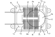
- the reactor of the present embodiment includes an annular core 1 having a rectangular opening at the center, and a coil 2 mounted on the annular core 1.
- the annular core 1 has two legs 1a arranged in parallel, and two yoke parts 1b arranged to connect the ends of the two legs 1a,
- the coil 2 is mounted on the outer periphery of the leg 1a.
- the annular core 1 comprises two U-shaped cores, each having a half length leg portion 1a provided on both sides of one yoke portion 1b, through the center gap of both legs. It is formed by abutting the parts 1a.
- the coil 2 forms a mounting portion 2a for the two legs 1a by winding one flat rectangular conductor in the middle to form the mounting portion 2a, and when the two U-shaped cores are butted, the inside of the mounting portion 2a
- the leg 1a of the annular core 1 is inserted into the At both ends of the coil 2, lead-out portions 2b are provided for connecting the coil 2 to an external power supply.
- the sensor core 3 is provided at a portion where the magnetic flux density is lower than the highest magnetic flux density among the portions of the leg portion 1 a where the coil 2 is not mounted at the corner portions between the leg portion 1 a and the yoke portion 1 b.
- the sensor core 3 is provided at a position expanding toward the outer periphery of the annular core 1 more than the arc surface connecting the outermost peripheral surfaces A and B of the two leg portions 1a and the outermost peripheral surface C of the yoke portion 1b.
- the edge core 1 is expanded toward the outer periphery than the above-described arc surface.
- the 1c portion is formed. That is, as shown in FIG. 5, since the substantially O-shaped magnetic path formed by the annular core 1 is concentrated at the corner portion on the inner side, the edge core 1c portion is outside the magnetic path and the magnetic flux density is relatively small. Become. Therefore, the sensor core 3 is provided in an edge core 1 c portion located outside the magnetic path formed in an arc shape and having a high magnetic flux density.
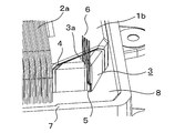
- the sensor core 3 is provided separately from the leg portion 1 a and the yoke portion 1 b so as to cut the edge core 1 c portion of the annular core 1, and is provided on the outer periphery of the annular core 1 via a gap sandwiching the heat insulating sheet 4. It is fixed.
- the sensor core 3 and the annular core 1 are connected at a part thereof by providing the gap to the middle of the cross section of the annular core 1 without completely separating the sensor core 3 from the annular core 1 by the gap. It is also possible.
- the sensor core 3 is provided with a notch 3 a so as to intersect the direction of the magnetic flux passing through the annular core 1.
- the notch 3 a is a slit formed vertically downward from the upper surface of the sensor core 3.
- a magnetic field detection element 5 such as a Hall element is mounted in the notch 3a.
- the lead wire 6 extending from the magnetic field detection element 5 protrudes on the surface of the sensor core 3 through the notch 3a.
- the current sensor includes a substrate (not shown) connected to the lead wire 6 to support the magnetic field detection element 5 and a connector (not shown) integrally provided with the substrate.
- the substrate is provided with an electronic component such as an ASIC for processing a signal from the magnetic field detection element 5, and an output portion of the electronic component is connected to an external device through a connector.
- the annular core 1, the sensor core 3 and the coil 2 are housed in a case 7 made of metal such as aluminum or resin.
- the space between the case 7 and the annular core 1 and the coil 2 is filled with a filler 8 such as a resin.
- the current sensor is fixed to the upper edge of the case 7 at a position facing the sensor core 3 by means such as screwing, bonding or fitting.
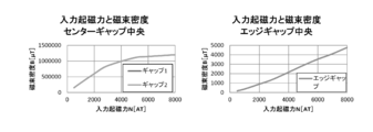
- sensor core 3 is provided at a portion where the magnetic flux density is lower than the magnetic flux density of leg portion 1 a at the corner portion between leg portion 1 a and yoke portion 1 b, sensor core 3 is saturated during operation of the reactor. As shown in the graph on the right side of FIG. 9, the input magnetomotive force and the magnetic flux density in that portion show a linear proportional relationship, and the detection of the conduction current of the coil 2 by the magnetic field detection element 5 is high. It is possible to do with accuracy.
- the sensor core 3 is provided at a position where the sensor core 3 bulges toward the outer periphery of the annular core 1 more than the arc surface connecting the outermost peripheral surface of the two leg portions 1a and the outermost peripheral surface of the yoke portion 1b.
- the magnetic flux density itself is low, the magnetic path from the leg portion 1a to the core portion is sufficiently secured inside the arc surface, so that the operation characteristics of the reactor are not adversely affected.
- the sensor core 3 is provided on the annular core 1 via the heat insulating sheet 4, the heat from the coil 2 generated at the time of energization is not transmitted via the annular core 1, and the heat of the magnetic field detection element 5 There is no fear of destruction or deterioration in detection accuracy, and the device options of the magnetic field detection element 5 are expanded.
- the four corner portions of the annular core 1 have the same shape, but even if only one or two corner portions are expanded to the outer peripheral side, the sensor core 3 may be provided in that portion good. Further, in the annular core 1 or the like having the arc-shaped yoke portion 1b described in Patent Document 1, instead of expanding the corner portion of the annular core 1, as in the third embodiment shown in FIG. It is also possible to fix a separate sensor core 3 to the outer peripheral surface of 1.
- the notch 3a in which the magnetic field detection element 5 is disposed may be formed from the outer peripheral side of the annular core 1 to the inside of the core, instead of being formed from the upper surface side of the annular core 1 toward the inside of the core.
- the notch 3a is preferably provided at right angles to the direction of the magnetic flux passing through the sensor core 3.
- the notch 3a is not necessarily perpendicular. It is good.
- the notch 3a and the magnetic flux detecting element do not have to be located completely outside the arc shown in FIG. 4, and the notch 3a and a part of the magnetic flux detecting element may be inserted inside the arc.
- the sensor core 3 may not necessarily be provided at the outermost peripheral portion of the corner as long as the minimum cross-sectional area of the main magnetic path is maintained so as not to affect the performance of the reactor. As in the fourth embodiment shown in FIG. 8, it may be provided at a position shifted to the side of the leg 1a or the yoke 1b with respect to the outermost peripheral part of the corner.
- the annular core 1 may be formed by combining the four core members constituting the leg portion 1a and the yoke portion 1b in a ring shape, in addition to forming the two U-shaped cores in combination. Further, each of the leg portion 1a and the yoke portion 1b does not have to be a single member, and may be composed of a plurality of core members connected via a gap.
- a member having a small cross-sectional area, ie, the cross-sectional area of the leg 1a or the yoke 1b may be determined so as to leave an equal cross-sectional area.
- the main magnetic flux passes through the cross-sectional area left at the corner portion, so that the linearity of the input magnetomotive force at the sensor core 3a portion is not saturated without the sensor core 3 portion provided with the notch portion 3a being saturated. Can be secured.
- the sensor core is provided at the portion where the magnetic flux density is low at the corner portion of the annular core, saturation of the sensor core is unlikely to occur even if the current flowing through the coil increases, and the linearity between the magnetic flux density and the input magnetomotive force is ensured.
- the detection accuracy of the energization current of the core by the magnetic field detection element provided in the sensor core portion is improved.
Landscapes
- Engineering & Computer Science (AREA)
- Power Engineering (AREA)
- Measuring Instrument Details And Bridges, And Automatic Balancing Devices (AREA)
Abstract
磁束密度と入力起電力の関係について直線性が維持できる電流センサ付きリアクトルを提供する。 環状コア11は、平行に配置された2本の脚部1aと、これら2本の脚部1aの端部同士を連結するように配置された2本のヨーク部1bとを有する。コイル2は脚部1aの少なくとも一方に装着される。センサコア3は脚部1aとヨーク部1bとのコーナー部において、環状コア11の外周面よりも環状コア11の外側に向かって突出する。 切欠部3aはセンサコア3に設けられる。電流センサの磁界検出素子5は切欠部3a内に装着される。
Description
本発明は、コイルに流れる電流を検出する機能を備えた電流センサ付きリアクトルに関する。
近年、環境対応によりEV、HEV等の環境対応車の開発が進んでいる。これらの車は電気によりモーターを駆動させるシステムであり、高圧バッテリー、コントロールユニット、モーターが組み合わされる。コントロールユニット内にはリアクトルが含まれており、リアクトルに印加される電流を検知するため、電流センサが用いられる。環境対応車の更なる高効率化に対応するには、ユニットの小型軽量化が不可避だがリアクトルと電流センサは一般的に別体であり、要求に対し不利である。
このような問題点を解決するため、例えば特許文献1に示すような電流センサ付きのリアクトルが提案されている。特許文献1のリアクトルでは、リアクトルを構成するコアの1部にスリットを設けておき、その内部に電流センサの磁界検出素子を配置し、その外側にコイルを巻き付けている。特許文献1には、スリットの代わりにコアに穴を開けたり、コアの外周面に磁界検出素子を配置する構成も記載されている。このような従来技術では、リアクトルの動作時においてコイルに流れる電流によりコアに磁束が発生するので、この磁束を磁界検出素子が検出することによって電流センサはコイルに流れる電流の値を検出することができる。
特許文献1に記載のリアクトルは、コアの両端が円弧状に湾曲しているUUコアと呼ばれるものであることから、コアを通る磁束の方向とコアの湾曲した形状とがほとんど一致している。一般的に、磁束はその発生源(リアクトルの場合はコイル)に対してループ状に形成され、磁気抵抗が最も小さく且つ最短の経路を通過しようとする。特許文献1の構造では、UUコアが作る概略O型の磁路に主たる磁界が形成されるが、上記理由によりコアの最内側に磁束が集まり、その部分の磁束密度が高くなり、外周部に近づくにつれて徐々に磁束密度が低下する傾向にある。しかし、UUコアは、その外周部が円弧状をしていることから、コアの外周部であっても磁束密度が高く、コイルに流れる電流が大きくなると飽和しやすい。
そのため、特許文献1のようにUUコアの一部やコアの外周面に磁界検出素子を設けた従来技術では、図9左側のグラフに示すように、コイルに流れる電流が増加して磁界検出素子への入力起磁力が大きくなるにつれて、磁束密度と入力起磁力との関係が直線的な比例関係を示すことがなくなる。その結果、電流センサの検出値の精度が低下する問題が生じる。
本発明は、上記のような従来技術の問題点を解消するために提案されたものである。本発明の目的は、電流センサ装着用のコア(以下、特許請求の範囲も含めてセンサコアと呼ぶ)を、リアクトル運転時における脚部の磁束密度よりも磁束密度の低い部分に設けることにより、磁束密度と入力起磁力との直線性を確保してコイル通電電流の検出精度を向上させた電流センサ付きリアクトルを提供することにある。
本発明の電流センサ付きリアクトルは、次のような構成を有することを特徴とする。
(1)平行に配置された2本の脚部と、これら2本の脚部の端部同士を連結するように配置された2本のヨーク部とを有する環状コア。
(2)前記脚部の少なくとも一方に装着されたコイル。
(3)前記脚部とヨーク部とのコーナー部において、前記脚部の磁束密度よりも磁束密度が低い部分に設けられたセンサコア。
(4)前記センサコアに設けられた切欠部。
(5)前記切欠部内に装着された電流センサの磁界検出素子。
(1)平行に配置された2本の脚部と、これら2本の脚部の端部同士を連結するように配置された2本のヨーク部とを有する環状コア。
(2)前記脚部の少なくとも一方に装着されたコイル。
(3)前記脚部とヨーク部とのコーナー部において、前記脚部の磁束密度よりも磁束密度が低い部分に設けられたセンサコア。
(4)前記センサコアに設けられた切欠部。
(5)前記切欠部内に装着された電流センサの磁界検出素子。
本発明は、次のような態様も包含する。
(6)前記センサコアは、前記2本の脚部の最外周面と前記ヨーク部の最外周面を結ぶ円弧面よりも環状コアの外周に向かって膨らんだ位置に設けられる。
(7)前記切欠部は、前記環状コアを通る磁束の方向に対して交差するように設けられる。
(8)前記センサコアは、前記環状コアとは別体に設けられ、断熱シートを介して環状コアの表面に固定される。
(6)前記センサコアは、前記2本の脚部の最外周面と前記ヨーク部の最外周面を結ぶ円弧面よりも環状コアの外周に向かって膨らんだ位置に設けられる。
(7)前記切欠部は、前記環状コアを通る磁束の方向に対して交差するように設けられる。
(8)前記センサコアは、前記環状コアとは別体に設けられ、断熱シートを介して環状コアの表面に固定される。
本発明によれば、センサコアが環状コアのコーナー部における磁束密度の低い部分に設けられているので、コイルの通電電流が大きくなってもセンサコアにおける飽和が発生し難く、磁束密度と入力起磁力との直線性が確保され、センサコア部分に設けた磁界検出素子によるコアの通電電流の検出精度が向上する。
以下、本発明の実施形態を、図面に従って具体的に説明する。
[1.第1実施形態]
(1)構成
本実施形態のリアクトルは、中央に四角形の開口部を有する環状コア1と、この環状コア1に装着されたコイル2を備える。環状コア1は、平行に配置された2本の脚部1aと、これら2本の脚部1aの端部同士を連結するように配置された2本のヨーク部1bを有し、2本の脚部1aの外周にコイル2が装着される。
[1.第1実施形態]
(1)構成
本実施形態のリアクトルは、中央に四角形の開口部を有する環状コア1と、この環状コア1に装着されたコイル2を備える。環状コア1は、平行に配置された2本の脚部1aと、これら2本の脚部1aの端部同士を連結するように配置された2本のヨーク部1bを有し、2本の脚部1aの外周にコイル2が装着される。
本実施形態において、環状コア1は、1本のヨーク部1bの両側に2分の1の長さの脚部1aをそれぞれ設けた2個のU字形コアを、センターギャップを介して両者の脚部1a同士を突き合わせることで形成される。コイル2は、1本の平角導体を途中で折り返すように巻回することで、2本の脚部1aに対する装着部2aを形成し、2つのU字形コアを突き合わせる際に装着部2aの内側に環状コア1の脚部1aを挿入する。コイル2の両端には、コイル2を外部の電源に接続する引出部2bが設けられる。
脚部1aとヨーク部1bとのコーナー部において、脚部1aのコイル2が装着されていない部分の中で最も高い磁束密度よりも磁束密度が低い部分にセンサコア3が設けられる。例えば、センサコア3は、2本の脚部1aの最外周面A,Bとヨーク部1bの最外周面Cを結ぶ円弧面よりも環状コア1の外周に向かって膨らんだ位置に設けられる。
本実施形態においては、環状コア1は、四角形に形成された脚部1aとヨーク部1bのコーナー部を斜めに面取りしたものであることから、前記の円弧面よりも外周に向かって膨らんだエッジコア1c部分が形成されている。すなわち、図5に示すように、環状コア1によって形成される概略O型の磁路はコーナー部においてその内側に集中するため、エッジコア1c部分は磁路にとって外側となり、相対的に磁束密度が小さくなる。そこで、センサコア3は、円弧状に形成される磁束密度が高い磁路の外側に位置するエッジコア1c部分に設けられる。
センサコア3は、環状コア1のエッジコア1c部分を切断するようにして、脚部1aやヨーク部1bとは別体に設けられ、断熱シート4を挟みこんだギャップを介して環状コア1の外周に固定される。この場合、ギャップによってセンサコア3を環状コア1と完全に別体とすることなく、ギャップを環状コア1の断面の途中まで設けることにより、センサコア3と環状コア1をその一部において繋がった形状とすることも可能である。
センサコア3には、環状コア1を通る磁束の方向に対して交差するように切欠部3aが設けられる。切欠部3aは、センサコア3の上面から下方に向かって垂直に形成されたスリットである。切欠部3a内に、ホール素子等の磁界検出素子5が装着される。磁界検出素子5から伸びるリード線6は、切欠部3aを通ってセンサコア3の表面に突出している。
電流センサはリード線6と接続されて磁界検出素子5を支持する基板(図示せず)と、この基板と一体に設けられたコネクタ(図示せず)を備える。基板には磁界検出素子5からの信号を処理するASICなどの電子部品が設けられ、この電子部品の出力部がコネクタを経由して外部機器に接続される。
環状コア1、センサコア3及びコイル2は、アルミニウム等の金属製或いは樹脂製のケース7内に収容される。ケース7と環状コア1及びコイル2の間の空隙部には、樹脂等の充填材8が充填される。ケース7の上縁部におけるセンサコア3に対向する位置に、電流センサがねじ止め、接着または嵌合等の手段により固定される。
(2)作用・効果
本実施形態においては、コイル2に通電するとその電流により環状コア1部分に磁界が発生して、リアクトルとしての機能が発揮される。同時に、環状コア1のコーナー部に設けられたセンサコア3に対しても、コイル2の通電電流の影響により漏れ磁束が生ずることにより、センサコア3の切欠部3aに設けられた磁界検出素子5がその漏れ磁束を検出する。センサコア3部分の漏れ磁束はコイル2の通電電流に比例することから、磁界検出素子5はコイル2の通電電流の大きさを計測することが可能となり、電流センサとして機能する。
本実施形態においては、コイル2に通電するとその電流により環状コア1部分に磁界が発生して、リアクトルとしての機能が発揮される。同時に、環状コア1のコーナー部に設けられたセンサコア3に対しても、コイル2の通電電流の影響により漏れ磁束が生ずることにより、センサコア3の切欠部3aに設けられた磁界検出素子5がその漏れ磁束を検出する。センサコア3部分の漏れ磁束はコイル2の通電電流に比例することから、磁界検出素子5はコイル2の通電電流の大きさを計測することが可能となり、電流センサとして機能する。
この場合、脚部1aとヨーク部1bとのコーナー部において、脚部1aの磁束密度よりも磁束密度が低い部分にセンサコア3が設けられていることから、リアクトルの運転時においてセンサコア3が飽和することがなく、その部分における入力起磁力と磁束密度が、図9右側のグラフに示すように、直線的な比例関係を示すことになり、磁界検出素子5によるコイル2の通電電流の検出を高精度で行うことが可能となる。また、センサコア3が、2本の脚部1aの最外周面とヨーク部1bの最外周面を結ぶ円弧面よりも環状コア1の外周に向かって膨らんだ位置に設けられているため、センサコア3自体は磁束密度が低いものの、脚部1aからコア部に掛けての磁路は円弧面の内側に充分確保されることになるので、リアクトルの運転特性に悪影響を与えることがない。
また、センサコア3は、断熱シート4を介して環状コア1に設けられているので、通電時に発生するコイル2からの熱が環状コア1を経由して伝わることがなく、磁界検出素子5の熱破壊や検出精度の低下の恐れがなく、磁界検出素子5のデバイス選択肢が広がる。
[2.他の実施形態]
本発明は、前記の実施形態に限定されるものではなく、例えば、次のような他の実施形態も包含する。
本発明は、前記の実施形態に限定されるものではなく、例えば、次のような他の実施形態も包含する。
(1)環状コア1の脚部1aやヨーク部1bに対して別体に形成する代わりに、図6に示す第2実施形態のように、ギャップや切り込みを設けることなく、環状コア1のコーナー部と一体に設けることも可能である。
(2)第1実施形態では、環状コア1の4カ所のコーナー部を同じ形状としたが、1カ所又は2カ所のコーナー部分のみを外周側に膨らませて、その部分にセンサコア3を設けても良い。また、特許文献1に記載された円弧状のヨーク部1bを有する環状コア1などにおいては、環状コア1のコーナー部を膨らませる代わりに、図7に示す第3実施形態のように、環状コア1の外周面に別体としたセンサコア3を固定することも可能である。
(3)磁界検出素子5を配置する切欠部3aは、環状コア1の上面側からコア内部に向かって形成する以外に、環状コア1の外周側からコア内部に向かって形成しても良い。また、切欠部3aはセンサコア3を通る磁束の方向に対して直角に設けることが望ましいが、磁束検出素子の特性によっては必ずしも直角である必要はなく、図示のスリット状以外に丸穴などであっても良い。また、切欠部3aや磁束検出素子は図4に示す円弧の完全に外側に位置する必要はなく、切欠部3aや磁束検出素子の一部が円弧の内側に入り込んでいても良い。
(4)センサコア3は、リアクトルの性能に影響を与えることがないように主磁路について最低限の断面積が維持されていれば、必ずしもコーナー部の最も外周部分に設けなくても良い。図8に示す第4実施形態のように、コーナー部の最も外周部分よりも脚部1a或いはヨーク部1b側にずれた位置に設けることもできる。
(5)環状コア1は、2つのU字形コアを組み合わせて形成する以外に、脚部1aとヨーク部1bを構成する4本のコア材を環状に組み合わせてもよい。また、脚部1aやヨーク部1bはそれぞれ1部材である必要はなく、ギャップを介して接続された複数本のコア材から構成されていても良い。
(6)脚部1aとヨーク部1bの断面積が異なる環状コア1にあっては、環状コア1のコーナー部において、断面積の小さい部材、すなわち脚部1aまたはヨーク部1bの断面積と略等しい断面積が残されるように、切欠部3aの位置を決定しても良い。このようにすると、コーナー部に残された断面積部分を主たる磁束が通ることになるので、切欠部3aを設けたセンサコア3部分が飽和することなく、センサコア3a部分における入力起磁力の直線性が確保できる。
センサコアが環状コアのコーナー部における磁束密度の低い部分に設けられているので、コイルの通電電流が大きくなってもセンサコアにおける飽和が発生し難く、磁束密度と入力起磁力との直線性が確保され、センサコア部分に設けた磁界検出素子によるコアの通電電流の検出精度が向上する。
1…環状コア
1a…脚部
1b…ヨーク部
1c…エッジコア
2…コイル
2a…装着部
2b…引出部
3…センサコア
3a…切欠部
4…断熱シート
5…磁界検出素子
6…リード線
7…ケース
8…充填材
1a…脚部
1b…ヨーク部
1c…エッジコア
2…コイル
2a…装着部
2b…引出部
3…センサコア
3a…切欠部
4…断熱シート
5…磁界検出素子
6…リード線
7…ケース
8…充填材
Claims (4)
- 平行に配置された2本の脚部と、これら2本の脚部の端部同士を連結するように配置された2本のヨーク部とを有する環状コアと、
前記脚部の少なくとも一方に装着されたコイルと、
前記脚部とヨーク部とのコーナー部において、前記脚部の磁束密度よりも磁束密度が低い部分に設けられたセンサコアと、
前記センサコアに設けられた切欠部と、
前記切欠部内に装着された電流センサの磁界検出素子と、
を備えている電流センサ付きリアクトル。 - 前記センサコアは、前記2本の脚部の最外周面と前記ヨーク部の最外周面を結ぶ円弧面よりも環状コアの外周に向かって膨らんだ位置に設けられる請求項1又は2に記載の電流センサ付きリアクトル。
- 前記切欠部は、前記環状コアを通る磁束の方向に対して交差するように設けられる請求項1に記載の電流センサ付きリアクトル。
- 前記センサコアは、前記環状コアとは別体に設けられ、断熱シートを介して環状コアの表面に固定される請求項1又は2に記載の電流センサ付きリアクトル。
Priority Applications (1)
| Application Number | Priority Date | Filing Date | Title |
|---|---|---|---|
| CN201880079983.9A CN111466003B (zh) | 2017-12-18 | 2018-10-11 | 带电流传感器的电抗器 |
Applications Claiming Priority (2)
| Application Number | Priority Date | Filing Date | Title |
|---|---|---|---|
| JP2017-242044 | 2017-12-18 | ||
| JP2017242044A JP7049749B2 (ja) | 2017-12-18 | 2017-12-18 | 電流センサ付きリアクトル |
Publications (1)
| Publication Number | Publication Date |
|---|---|
| WO2019123790A1 true WO2019123790A1 (ja) | 2019-06-27 |
Family
ID=66994016
Family Applications (1)
| Application Number | Title | Priority Date | Filing Date |
|---|---|---|---|
| PCT/JP2018/037946 Ceased WO2019123790A1 (ja) | 2017-12-18 | 2018-10-11 | 電流センサ付きリアクトル |
Country Status (3)
| Country | Link |
|---|---|
| JP (1) | JP7049749B2 (ja) |
| CN (1) | CN111466003B (ja) |
| WO (1) | WO2019123790A1 (ja) |
Citations (3)
| Publication number | Priority date | Publication date | Assignee | Title |
|---|---|---|---|---|
| JP2009026995A (ja) * | 2007-07-20 | 2009-02-05 | Toyota Motor Corp | リアクトルコアおよびリアクトル |
| JP5252207B2 (ja) * | 2008-03-31 | 2013-07-31 | 住友電気工業株式会社 | リアクトル、及びコンバータ |
| JP2017139397A (ja) * | 2016-02-05 | 2017-08-10 | スミダコーポレーション株式会社 | 磁性部品 |
Family Cites Families (3)
| Publication number | Priority date | Publication date | Assignee | Title |
|---|---|---|---|---|
| JP5316871B2 (ja) * | 2009-05-22 | 2013-10-16 | 住友電気工業株式会社 | リアクトル、及びコンバータ |
| JP2013098302A (ja) * | 2011-10-31 | 2013-05-20 | Sumitomo Electric Ind Ltd | リアクトル |
| JP5950246B2 (ja) * | 2012-01-19 | 2016-07-13 | 住友電気工業株式会社 | リアクトル |
-
2017
- 2017-12-18 JP JP2017242044A patent/JP7049749B2/ja active Active
-
2018
- 2018-10-11 CN CN201880079983.9A patent/CN111466003B/zh active Active
- 2018-10-11 WO PCT/JP2018/037946 patent/WO2019123790A1/ja not_active Ceased
Patent Citations (3)
| Publication number | Priority date | Publication date | Assignee | Title |
|---|---|---|---|---|
| JP2009026995A (ja) * | 2007-07-20 | 2009-02-05 | Toyota Motor Corp | リアクトルコアおよびリアクトル |
| JP5252207B2 (ja) * | 2008-03-31 | 2013-07-31 | 住友電気工業株式会社 | リアクトル、及びコンバータ |
| JP2017139397A (ja) * | 2016-02-05 | 2017-08-10 | スミダコーポレーション株式会社 | 磁性部品 |
Also Published As
| Publication number | Publication date |
|---|---|
| JP2019110202A (ja) | 2019-07-04 |
| CN111466003A (zh) | 2020-07-28 |
| CN111466003B (zh) | 2021-09-07 |
| JP7049749B2 (ja) | 2022-04-07 |
Similar Documents
| Publication | Publication Date | Title |
|---|---|---|
| JP4823585B2 (ja) | 磁石式発電機 | |
| JPH1169749A (ja) | モータ構造及びその製造方法 | |
| JP2012225921A (ja) | 磁気コアを備えている電流センサ | |
| US20140009031A1 (en) | Motor stator and motor | |
| JP6578093B2 (ja) | 磁気結合型リアクトル | |
| JP4803256B2 (ja) | ブラシレスモータ | |
| JP2014160035A (ja) | 電流センサ | |
| JP5252207B2 (ja) | リアクトル、及びコンバータ | |
| JP2009136090A (ja) | ロータプレート | |
| JP6106646B2 (ja) | リアクトル | |
| JP5428334B2 (ja) | 電動機 | |
| JP4331122B2 (ja) | コイル部品及びリアクトル | |
| JP2010266209A (ja) | 電流センサ | |
| JP2019110202A (ja) | 電流センサ付きリアクトル | |
| JP5834969B2 (ja) | リアクトル | |
| JP2010268650A (ja) | アキシャルギャップ型回転電機 | |
| JP2009077491A (ja) | ステータコア積層体およびモータ | |
| JP2015119523A (ja) | レゾルバ | |
| JP2019012760A (ja) | インダクタンス素子及びlcフィルタ | |
| JP4890506B2 (ja) | 電流検出器 | |
| JP5212862B2 (ja) | 永久磁石形回転電機 | |
| WO2015114794A1 (ja) | アキシャルギャップ型回転電機 | |
| JP6084407B2 (ja) | リアクトル | |
| JP2019071358A (ja) | リアクトル | |
| JP7085853B2 (ja) | 回転電機、回転電機の製造方法、および送風機 |
Legal Events
| Date | Code | Title | Description |
|---|---|---|---|
| 121 | Ep: the epo has been informed by wipo that ep was designated in this application |
Ref document number: 18890115 Country of ref document: EP Kind code of ref document: A1 |
|
| NENP | Non-entry into the national phase |
Ref country code: DE |
|
| 122 | Ep: pct application non-entry in european phase |
Ref document number: 18890115 Country of ref document: EP Kind code of ref document: A1 |