WO2019116451A1 - ショベル - Google Patents
ショベル Download PDFInfo
- Publication number
- WO2019116451A1 WO2019116451A1 PCT/JP2017/044610 JP2017044610W WO2019116451A1 WO 2019116451 A1 WO2019116451 A1 WO 2019116451A1 JP 2017044610 W JP2017044610 W JP 2017044610W WO 2019116451 A1 WO2019116451 A1 WO 2019116451A1
- Authority
- WO
- WIPO (PCT)
- Prior art keywords
- digging
- excavation
- load
- boom
- cylinder
- Prior art date
Links
Images


Classifications
-
- E—FIXED CONSTRUCTIONS
- E02—HYDRAULIC ENGINEERING; FOUNDATIONS; SOIL SHIFTING
- E02F—DREDGING; SOIL-SHIFTING
- E02F3/00—Dredgers; Soil-shifting machines
- E02F3/04—Dredgers; Soil-shifting machines mechanically-driven
- E02F3/28—Dredgers; Soil-shifting machines mechanically-driven with digging tools mounted on a dipper- or bucket-arm, i.e. there is either one arm or a pair of arms, e.g. dippers, buckets
-
- E—FIXED CONSTRUCTIONS
- E02—HYDRAULIC ENGINEERING; FOUNDATIONS; SOIL SHIFTING
- E02F—DREDGING; SOIL-SHIFTING
- E02F9/00—Component parts of dredgers or soil-shifting machines, not restricted to one of the kinds covered by groups E02F3/00 - E02F7/00
- E02F9/24—Safety devices, e.g. for preventing overload
-
- E—FIXED CONSTRUCTIONS
- E02—HYDRAULIC ENGINEERING; FOUNDATIONS; SOIL SHIFTING
- E02F—DREDGING; SOIL-SHIFTING
- E02F3/00—Dredgers; Soil-shifting machines
- E02F3/04—Dredgers; Soil-shifting machines mechanically-driven
- E02F3/28—Dredgers; Soil-shifting machines mechanically-driven with digging tools mounted on a dipper- or bucket-arm, i.e. there is either one arm or a pair of arms, e.g. dippers, buckets
- E02F3/30—Dredgers; Soil-shifting machines mechanically-driven with digging tools mounted on a dipper- or bucket-arm, i.e. there is either one arm or a pair of arms, e.g. dippers, buckets with a dipper-arm pivoted on a cantilever beam, i.e. boom
- E02F3/32—Dredgers; Soil-shifting machines mechanically-driven with digging tools mounted on a dipper- or bucket-arm, i.e. there is either one arm or a pair of arms, e.g. dippers, buckets with a dipper-arm pivoted on a cantilever beam, i.e. boom working downwardly and towards the machine, e.g. with backhoes
-
- E—FIXED CONSTRUCTIONS
- E02—HYDRAULIC ENGINEERING; FOUNDATIONS; SOIL SHIFTING
- E02F—DREDGING; SOIL-SHIFTING
- E02F3/00—Dredgers; Soil-shifting machines
- E02F3/04—Dredgers; Soil-shifting machines mechanically-driven
- E02F3/28—Dredgers; Soil-shifting machines mechanically-driven with digging tools mounted on a dipper- or bucket-arm, i.e. there is either one arm or a pair of arms, e.g. dippers, buckets
- E02F3/36—Component parts
- E02F3/42—Drives for dippers, buckets, dipper-arms or bucket-arms
- E02F3/43—Control of dipper or bucket position; Control of sequence of drive operations
- E02F3/435—Control of dipper or bucket position; Control of sequence of drive operations for dipper-arms, backhoes or the like
-
- E—FIXED CONSTRUCTIONS
- E02—HYDRAULIC ENGINEERING; FOUNDATIONS; SOIL SHIFTING
- E02F—DREDGING; SOIL-SHIFTING
- E02F9/00—Component parts of dredgers or soil-shifting machines, not restricted to one of the kinds covered by groups E02F3/00 - E02F7/00
- E02F9/20—Drives; Control devices
- E02F9/2025—Particular purposes of control systems not otherwise provided for
- E02F9/2029—Controlling the position of implements in function of its load, e.g. modifying the attitude of implements in accordance to vehicle speed
-
- E—FIXED CONSTRUCTIONS
- E02—HYDRAULIC ENGINEERING; FOUNDATIONS; SOIL SHIFTING
- E02F—DREDGING; SOIL-SHIFTING
- E02F9/00—Component parts of dredgers or soil-shifting machines, not restricted to one of the kinds covered by groups E02F3/00 - E02F7/00
- E02F9/20—Drives; Control devices
- E02F9/2025—Particular purposes of control systems not otherwise provided for
- E02F9/2033—Limiting the movement of frames or implements, e.g. to avoid collision between implements and the cabin
-
- E—FIXED CONSTRUCTIONS
- E02—HYDRAULIC ENGINEERING; FOUNDATIONS; SOIL SHIFTING
- E02F—DREDGING; SOIL-SHIFTING
- E02F9/00—Component parts of dredgers or soil-shifting machines, not restricted to one of the kinds covered by groups E02F3/00 - E02F7/00
- E02F9/26—Indicating devices
- E02F9/264—Sensors and their calibration for indicating the position of the work tool
- E02F9/265—Sensors and their calibration for indicating the position of the work tool with follow-up actions (e.g. control signals sent to actuate the work tool)
-
- E—FIXED CONSTRUCTIONS
- E02—HYDRAULIC ENGINEERING; FOUNDATIONS; SOIL SHIFTING
- E02F—DREDGING; SOIL-SHIFTING
- E02F9/00—Component parts of dredgers or soil-shifting machines, not restricted to one of the kinds covered by groups E02F3/00 - E02F7/00
- E02F9/20—Drives; Control devices
- E02F9/22—Hydraulic or pneumatic drives
- E02F9/2203—Arrangements for controlling the attitude of actuators, e.g. speed, floating function
-
- E—FIXED CONSTRUCTIONS
- E02—HYDRAULIC ENGINEERING; FOUNDATIONS; SOIL SHIFTING
- E02F—DREDGING; SOIL-SHIFTING
- E02F9/00—Component parts of dredgers or soil-shifting machines, not restricted to one of the kinds covered by groups E02F3/00 - E02F7/00
- E02F9/20—Drives; Control devices
- E02F9/22—Hydraulic or pneumatic drives
- E02F9/226—Safety arrangements, e.g. hydraulic driven fans, preventing cavitation, leakage, overheating
Definitions
- the present disclosure relates to a shovel capable of detecting the posture of a digging attachment.
- the digging reaction force may be increased.
- the shovel of Patent Document 1 raises the boom regardless of whether deep excavation or normal excavation is performed if the calculated excavating reaction force is larger than a preset upper limit value. Therefore, the digging reaction force is increased in an attempt to reduce the digging reaction force at the time of the deep digging, and the digging reaction force may be increased, so that the digging can not be continued and the working efficiency may be reduced.
- a shovel includes a lower traveling body, an upper revolving superstructure mounted on the lower traveling body, an excavating attachment attached to the upper revolving superstructure, and an attitude detecting device for detecting an attitude of the excavating attachment
- a shovel having an unstable state detection device for detecting information on the unstable state of the upper swing body due to a digging load, and a control device for correcting the attitude of the digging attachment, the control device comprising: When it is determined that the digging load during deep digging is larger than a predetermined value based on the outputs of the posture detection device and the unstable state detecting device, the arm or the bucket configuring the digging attachment is opened.
- a shovel is provided which can more appropriately control the drilling attachment during deep excavation.
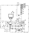
- FIG. 1 is a side view of a shovel according to an embodiment of the present invention.
- An upper swing body 3 is rotatably mounted on the lower traveling body 1 of the shovel shown in FIG. 1 via a turning mechanism 2.
- a boom 4 is attached to the upper swing body 3.
- An arm 5 is attached to the tip of the boom 4, and a bucket 6 is attached to the tip of the arm 5.
- the boom 4 as a working element, the arm 5 and the bucket 6 constitute a digging attachment which is an example of an attachment.
- the boom 4, the arm 5 and the bucket 6 are hydraulically driven by the boom cylinder 7, the arm cylinder 8 and the bucket cylinder 9 respectively.
- a cabin 10 is provided in the upper revolving superstructure 3 and a power source such as an engine 11 is mounted.
- a posture detection device M1 is attached to the excavation attachment.
- the posture detection device M1 is a device that detects the posture of the digging attachment.
- the posture detection device M1 includes a boom angle sensor M1a, an arm angle sensor M1b, and a bucket angle sensor M1c.
- the boom angle sensor M1a is a sensor that acquires a boom angle, and for example, a rotation angle sensor that detects a rotation angle of a boom foot pin, a stroke sensor that detects a stroke amount of the boom cylinder 7, and an inclination angle of the boom 4 Includes tilt (acceleration) sensor and so on.
- the boom angle sensor M1a may be an inertial measurement device configured by a combination of a gyro sensor and an acceleration sensor. The same applies to the arm angle sensor M1b and the bucket angle sensor M1c.
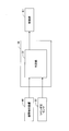
- FIG. 2 is a side view of the shovel showing various physical quantities related to the digging attachment.
- the boom angle sensor M1a acquires, for example, a boom angle ( ⁇ 1).
- the boom angle ( ⁇ 1) is an angle with respect to a horizontal line of a line segment P1-P2 connecting the boom foot pin position P1 and the arm connecting pin position P2 in the XZ plane.
- the arm angle sensor M1b acquires, for example, an arm angle ( ⁇ 2).
- the arm angle ( ⁇ 2) is an angle with respect to a horizontal line of a line segment P2-P3 connecting the arm connecting pin position P2 and the bucket connecting pin position P3 in the XZ plane.
- the bucket angle sensor M1c acquires, for example, a bucket angle ( ⁇ 3).
- the bucket angle ( ⁇ 3) is an angle with respect to a horizontal line of a line segment P3-P4 connecting the bucket connecting pin position P3 and the bucket toe position P4 in the XZ plane.
- the basic system of the shovel mainly includes an engine 11, a main pump 14, a pilot pump 15, a control valve 17, an operating device 26, a controller 30, an engine control device 74, and the like.
- the engine 11 is a driving source of a shovel, and is, for example, a diesel engine that operates to maintain a predetermined rotational speed.
- the output shaft of the engine 11 is connected to the input shaft of the main pump 14 and the pilot pump 15.
- the main pump 14 is a hydraulic pump that supplies hydraulic fluid to the control valve 17 via a hydraulic fluid line 16, and is, for example, a swash plate type variable displacement hydraulic pump.
- the stroke length of the piston for determining the displacement volume is changed according to the change of the swash plate tilt angle, and the discharge flow rate per one rotation is changed.
- the swash plate tilt angle is controlled by the regulator 14a.
- the regulator 14 a changes the swash plate tilt angle according to the change of the control current from the controller 30. For example, the regulator 14a increases the swash plate tilting angle according to the increase of the control current to increase the discharge flow rate of the main pump 14.
- the regulator 14a reduces the discharge flow rate of the main pump 14 by reducing the inclination angle of the swash plate in accordance with the decrease of the control current.
- the discharge pressure sensor 14 b detects the discharge pressure of the main pump 14.
- the oil temperature sensor 14 c detects the temperature of the hydraulic oil drawn by the main pump 14.
- the pilot pump 15 is a hydraulic pump for supplying hydraulic fluid to various hydraulic control devices such as the operating device 26 via the pilot line 25 and is, for example, a fixed displacement hydraulic pump.
- the control valve 17 is a set of flow control valves that control the flow of hydraulic fluid related to the hydraulic actuator.
- the control valve 17 selectively supplies hydraulic oil received from the main pump 14 through the hydraulic oil line 16 to one or more hydraulic actuators in response to a change in pilot pressure corresponding to the operating direction and the operating amount of the operating device 26.
- the hydraulic actuator includes, for example, a boom cylinder 7, an arm cylinder 8, a bucket cylinder 9, a left traveling hydraulic motor 1A, a right traveling hydraulic motor 1B, a turning hydraulic motor 2A, and the like.
- the operating device 26 is a device used by the operator for operating the hydraulic actuator, and includes a lever 26A, a lever 26B, a pedal 26C, and the like.
- the operating device 26 receives the supply of hydraulic fluid from the pilot pump 15 via the pilot line 25 to generate a pilot pressure. Then, the pilot pressure is applied to the pilot port of the corresponding flow control valve through the pilot line 25a. The pilot pressure changes in accordance with the operating direction and the operating amount of the operating device 26.
- the operating device 26 may be operated remotely. In this case, the controller device 26 generates a pilot pressure in accordance with the information on the operation direction and the amount of operation received via wireless communication.
- the controller 30 is a control device for controlling a shovel.
- the controller 30 is configured by a computer provided with a CPU, a RAM, a ROM, and the like.
- the CPU of the controller 30 reads out programs corresponding to various functions from the ROM, loads them into the RAM, and executes them, thereby realizing functions corresponding to the respective programs.
- the controller 30 realizes a function of controlling the discharge flow rate of the main pump 14. Specifically, the controller 30 changes the control current to the regulator 14a according to the negative control pressure of the negative control valve, and controls the discharge flow rate of the main pump 14 via the regulator 14a.
- the engine control device 74 is a device that controls the engine 11.
- the engine control device 74 controls, for example, the fuel injection amount and the like so that the engine rotational speed set via the input device is realized.
- the operation mode switching dial 75 is a dial for switching the operation mode of the shovel, and is provided in the cabin 10. In this embodiment, the operator can switch between the M (manual) mode and the SA (semi-automatic) mode.
- the controller 30 switches the operating mode of the shovel, for example, according to the output of the operating mode switching dial 75.
- FIG. 3 shows a state in which the SA mode is selected by the operation mode switching dial 75.
- the M mode is a mode in which the shovel is operated according to the content of the operation input to the operation device 26 by the operator.
- the mode is a mode in which the boom cylinder 7, the arm cylinder 8, the bucket cylinder 9, and the like are operated according to the content of the operation input to the operation device 26 by the operator.
- the SA mode is a mode in which the shovel is automatically operated regardless of the content of the operation input to the operation device 26 when a predetermined condition is satisfied. For example, when a predetermined condition is satisfied, the boom cylinder 7, the arm cylinder 8, the bucket cylinder 9, etc. are automatically operated regardless of the content of the operation input to the operation device 26.
- the operation mode switching dial 75 may be configured to switch between three or more operation modes.
- the display device 40 is a device that displays various information, and is disposed in the vicinity of the driver's seat in the cabin 10.
- the display device 40 has an image display unit 41 and an input unit 42.
- An operator can input information and commands to the controller 30 using the input unit 42.
- the operating condition and control information of the shovel can be grasped by looking at the image display unit 41.
- the display device 40 is connected to the controller 30 via a communication network such as CAN. However, the display device 40 may be connected to the controller 30 via a dedicated line.
- the display device 40 operates by receiving the supply of power from the storage battery 70.
- the storage battery 70 is charged with the power generated by the alternator 11a.
- the electric power of the storage battery 70 is supplied to components other than the controller 30 and the display device 40, such as the electrical component 72 of the shovel.
- the starter 11 b of the engine 11 is driven by the power from the storage battery 70 to start the engine 11.
- the engine 11 is controlled by an engine control device 74.
- the engine control device 74 transmits various data indicating the state of the engine 11 (for example, data indicating the cooling water temperature (physical quantity) detected by the water temperature sensor 11 c) to the controller 30.
- the controller 30 can store the data in the temporary storage unit (memory) 30 a and can transmit the data to the display device 40 as needed.
- Data indicating the swash plate tilt angle output from the regulator 14a, data indicating the discharge pressure of the main pump 14 output from the discharge pressure sensor 14b, data indicating the hydraulic oil temperature output from the oil temperature sensor 14c, pilot pressure sensor 15a The same applies to data indicating the pilot pressure output by 15b.
- the cylinder pressure sensor S1 is an example of an unstable state detection device that detects information related to the unstable state of the upper swing body 3 due to digging load, detects cylinder pressure of a hydraulic cylinder, and outputs detection data to the controller 30 Do.
- the unstable state of the upper swing body 3 includes, for example, a state in which the rear end of the upper swing body 3 is easily lifted.
- the cylinder pressure includes, for example, boom cylinder pressure, arm cylinder pressure and bucket cylinder pressure.
- the cylinder pressure sensor S1 includes cylinder pressure sensors S11 to S16. Specifically, the cylinder pressure sensor S11 detects a boom bottom pressure which is the pressure of the hydraulic fluid in the bottom side oil chamber of the boom cylinder 7.
- the cylinder pressure sensor S12 detects a boom rod pressure which is the pressure of the hydraulic fluid in the rod side oil chamber of the boom cylinder 7.
- the cylinder pressure sensor S13 detects arm bottom pressure
- the cylinder pressure sensor S14 detects arm rod pressure
- the cylinder pressure sensor S15 detects bucket bottom pressure
- the cylinder pressure sensor S16 detects bucket rod pressure .
- Boom cylinder pressure includes boom rod pressure and boom bottom pressure.
- Arm cylinder pressure includes arm rod pressure and arm bottom pressure.
- Bucket cylinder pressure includes bucket rod pressure and bucket bottom pressure.
- the control valve E1 is a valve that operates in response to a command from the controller 30.
- the control valve E1 is used to forcibly operate the flow control valve for a predetermined hydraulic cylinder regardless of the content of the operation input to the operating device 26.
- FIG. 4 is a diagram showing a configuration example of a digging control system mounted on the shovel of FIG.
- the excavation control system mainly includes an attitude detection device M1, a cylinder pressure sensor S1, a controller 30, and a control valve E1.
- the controller 30 includes a determination unit 31.
- the determination unit 31 is a functional element that determines whether or not the posture of the digging attachment during digging should be corrected. For example, when it is determined that there is a possibility that the excavation load may become excessively large, the determination unit 31 determines that the posture of the excavation attachment being excavated should be corrected.
- the determination unit 31 derives and records the digging load based on the output of the cylinder pressure sensor S1. Moreover, the empty excavation load corresponding to the attitude of the digging attachment detected by the attitude detection device M1 is derived. Then, the determination unit 31 subtracts the empty drilling load from the drilling load to calculate a net drilling load, and determines whether to correct the posture of the drilling attachment based on the net drilling load.
- the determination unit 31 may take into consideration the inclination of the upper swing body 3 detected by the vehicle body inclination sensor S2, which is another example of the unstable state detection device, when the empty excavation load is derived.
- the vehicle body inclination sensor S2 is configured of, for example, an acceleration sensor, a gyro sensor, an inertial measurement device, or the like.
- Drilling means moving the drilling attachment while bringing the drilling attachment into contact with the drilling object such as earth and sand, and "empty drilling” means moving the drilling attachment without bringing the drilling attachment into contact with any feature.
- Drilling load means the load when moving the drilling attachment while contacting with the drilling target
- empty drilling load means the load when moving the drilling attachment without contacting any feature.
- the “drilling load” is also referred to as “drilling resistance”.
- the “drilling load”, the “empty drilling load”, and the “net drilling load” are respectively represented by arbitrary physical quantities such as cylinder pressure, cylinder thrust, drilling torque (moment of drilling force), drilling reaction force and the like.
- a net cylinder pressure as a net excavation load is expressed as a value obtained by subtracting an empty excavation cylinder pressure as an empty excavation load from a cylinder pressure as an excavation load. The same applies to the case of using cylinder thrust, digging torque (moment of digging force), digging reaction force and the like.
- a detection value of a cylinder pressure sensor S1 is used as the cylinder pressure.
- the detection values of the cylinder pressure sensor S1 are, for example, boom bottom pressure (P11), boom rod pressure (P12), arm bottom pressure (P13), arm rod pressure (P14), bucket bottom pressure detected by the cylinder pressure sensors S11 to S16, bucket bottom Pressure (P15) and bucket rod pressure (P16).
- the cylinder thrust is calculated based on, for example, the cylinder pressure and the pressure receiving area of the piston sliding in the cylinder.
- the cylinder extension force (P11 ⁇ A11) which is the product of the boom bottom pressure (P11) and the pressure receiving area (A11) of the piston in the boom bottom side oil chamber is the boom cylinder thrust (f1). It is expressed by the difference (P11 ⁇ A11 ⁇ P12 ⁇ A12) of the cylinder contraction force which is the product (P12 ⁇ A12) of the boom rod pressure (P12) and the pressure receiving area (A12) of the piston in the boom rod side oil chamber Ru.
- the arm cylinder thrust (f2) and the bucket cylinder thrust (f3) The same applies to the arm cylinder thrust (f2) and the bucket cylinder thrust (f3).
- the digging torque is calculated based on, for example, the posture of the digging attachment and the cylinder thrust.
- the magnitude of the bucket digging torque ( ⁇ 3) is equal to the magnitude of the bucket cylinder thrust (f3), and the distance between the operating line of the bucket cylinder thrust (f3) and the bucket connecting pin position P3. It is represented by a value multiplied by G3.
- the distance G3 is a function of the bucket angle ( ⁇ 3), and is an example of the link gain. The same applies to the boom digging torque ( ⁇ 1) and the arm digging torque ( ⁇ 2).
- the digging reaction force is calculated based on, for example, the posture of the digging attachment and the digging load.
- the digging reaction force F is calculated based on a function (mechanistic function) having a physical quantity representing the posture of the digging attachment as an argument and a function having a physical quantity representing the digging load as an argument.
- the digging reaction force F is a mechanical function having a boom angle ( ⁇ 1), an arm angle ( ⁇ 2) and a bucket angle ( ⁇ 3) as arguments, a boom digging torque ( ⁇ 1), an arm It is calculated as a product of a digging torque ( ⁇ 2) and a function with the bucket digging torque ( ⁇ 3) as arguments.
- the functions with boom digging torque ( ⁇ 1), arm digging torque ( ⁇ 2) and bucket digging torque ( ⁇ 3) as arguments are boom cylinder thrust (f1), arm cylinder thrust (f2) and bucket cylinder thrust (f3) as arguments It may be a function that
- boom angle ( ⁇ 1), arm angle ( ⁇ 2) and bucket angle ( ⁇ 3) may be based on force balance equation, may be based on Jacobian, or may be virtual work It may be based on the principle.
- the digging load is derived based on the currently detected values of the various sensors.
- the detection value of the cylinder pressure sensor S1 may be used as it is as a digging load.
- the cylinder thrust calculated based on the detection value of the cylinder pressure sensor S1 may be used as the digging load.
- the digging torque calculated from the cylinder thrust calculated on the basis of the detection value of the cylinder pressure sensor S1 and the posture of the digging attachment derived on the basis of the detection value of the posture detection device M1 may be used as a digging load Good. The same applies to the digging reaction force.
- the empty excavation load may be stored in advance in association with the posture of the excavation attachment.
- an empty drilling cylinder pressure table is used that stores empty drilling cylinder pressure as empty drilling load in a referential manner in association with the combination of boom angle ( ⁇ 1), arm angle ( ⁇ 2) and bucket angle ( ⁇ 3) Good.
- an empty drilling cylinder thrust table is used that stores empty drill cylinder thrusts as empty drilling loads in association with combinations of boom angle ( ⁇ 1), arm angle ( ⁇ 2) and bucket angle ( ⁇ 3). Good.
- the controller 30 It may be stored in advance in the ROM or the like. Or you may produce
- the empty drilling cylinder pressure table, the empty drilling cylinder thrust table, the empty drilling torque table, and the empty drilling reaction force table may be prepared for each operation speed of the drilling attachment such as high speed, medium speed, and low speed. Also, it may be prepared for each operation content of the excavating attachment such as when the arm is closed, when the arm is opened, when the boom is raised, and when the boom is lowered.
- the determination unit 31 determines that the excavating load may be excessive. For example, the determination unit 31 determines that the cylinder pressure as the digging load may become excessive when the net cylinder pressure as the net digging load becomes equal to or higher than a predetermined cylinder pressure.
- the predetermined cylinder pressure may be a fluctuation value that changes according to a change in the attitude of the digging attachment, or may be a fixed value that does not change according to a change in the attitude of the digging attachment.
- the determination unit 31 determines that the posture of the digging attachment under digging should be corrected, and the control valve E1. Output a command to
- Control valve E1 receiving the command from determination unit 31 forcibly operates the flow control valve for a predetermined hydraulic cylinder regardless of the content of the operation input to operating device 26, and forcibly extends and contracts the predetermined hydraulic cylinder.
- the control valve E1 forcibly extends the boom cylinder 7 by forcibly moving the flow control valve related to the boom cylinder 7.
- the drilling depth can be made shallow by forcibly raising the boom 4.
- the control valve E1 may forcibly extend the bucket cylinder 9 by forcibly moving the flow control valve related to the bucket cylinder 9.
- the bucket toe angle can be adjusted to make the digging depth shallow.
- the bucket toe angle is, for example, the angle of the toe of the bucket 6 with respect to the horizontal plane.
- the control valve E1 can reduce the digging depth by forcibly expanding and / or contracting at least one of the boom cylinder 7 and the bucket cylinder 9.
- the determination unit 31 makes the correction content of the posture of the excavation attachment in the case where the deep excavation is performed different from the correction content as described above in the case where the normal excavation is performed.
- the determination unit 31 determines whether deep excavation or normal excavation is in progress based on the posture of the excavation attachment.
- the determination unit 31 may determine whether deep digging or normal digging is in progress based on the attitude of the boom 4 or based on the attitude of the boom 4 and the attitude of the arm 5.
- FIG. 5 is a side view of the shovel showing the transition of the posture of the digging attachment.
- Fig. 5 (A1) to Fig. 5 (A3) show the transition of the posture of the excavating attachment when the normal excavation is performed
- Fig. 5 (B1) to Fig. 5 (B3) shows the state when the deep excavation is performed. Indicates the transition of the attitude of the drilling attachment.
- Normal excavating means excavating in the case where the moment of excavating reaction force to turn the shovel forward does not have to exceed the moment of self weight of the shovel to prevent the shovel from turning forward.
- the excavation depth D1 is excavating below a predetermined depth (for example, 2 meters).
- the digging depth means, for example, the depth of the point of application of the digging reaction force to the horizontal plane including the ground contact surface of the lower traveling body 1.
- the digging depth has a negative value, which means the digging height.
- “Deep excavation” means excavation where there is a possibility that the moment of the digging reaction force for turning the shovel forward may exceed the moment of self weight of the shovel preventing the shovel from turning forward.
- the digging depth D2 is digging of a predetermined depth (eg, 2 meters) or more.
- the determination unit 31 may determine “deep digging” when the boom angle ( ⁇ 1) is less than a predetermined value regardless of the position of the work site such as the bucket toe position P4.
- the determination unit 31 determines whether or not the bucket 6 is in contact with the ground based on, for example, the outputs of the pilot pressure sensors 15a and 15b and the cylinder pressure sensors S11 to S16. It is for determining whether it is under excavation.
- the determination unit 31 derives the bucket toe position P4 based on the detection value of the posture detection device M1, and sets the absolute value as the digging depth when the value of the Z coordinate of the bucket toe position P4 is a negative value. And if the excavation depth is more than predetermined depth, it will be judged as deep excavation and it will be judged as normal excavation if it is less than predetermined depth.
- the determination unit 31 determines whether or not the digging load may become excessive. Then, when it is determined that the excavation load may become excessive during normal excavation, the determination unit 31 forcibly extends the boom cylinder 7 as described above and forcibly raises the boom 4.
- the determination unit 31 forcibly contracts the arm cylinder 8 to forcibly move the arm 5 instead of forcibly raising the boom 4.
- Force open Alternatively, the bucket cylinder 9 is forcibly contracted to forcibly open the bucket 6.
- the arm 5 and the bucket 6 may be opened simultaneously. The reason is to reduce the digging reaction force, and if the boom 4 is forcedly raised to make the digging depth shallow when digging deeply, the digging reaction force may be increased.
- the determination unit 31 determines whether the digging load may become excessive during deep excavation based on the output of the vehicle body inclination sensor S2 attached to the rear end of the upper swing body 3, ie, the upper swing body It may be determined whether or not 3 is likely to be unstable. Based on the inclination of the upper swing body 3, the determination unit 31 determines whether the moment of the digging reaction force for turning the shovel forward may exceed the moment of the weight of the shovel that prevents the shovel from turning forward. It is because it can be determined.
- the determination unit 31 detects that the rear end of the upper swing body 3 has started to rise, for example, based on the output of the vehicle body inclination sensor S2, the digging load may become excessive, that is, It is determined that the upper swing body 3 may be in an unstable state.
- the determination unit 31 may determine whether the excavation is a normal excavation or a deep excavation. Also, the determination as to whether or not excavation is in progress may be omitted. Alternatively, the determination as to whether or not the excavation is in progress, the determination as to the normal excavation or the deep excavation, and the determination as to whether or not the excavation load may become excessive may be performed simultaneously.
- FIG. 6 is a flowchart of the determination process.
- SA sin-automatic
- the determination unit 31 of the controller 30 acquires data on the excavation attachment (step ST1).
- the determining unit 31 acquires, for example, a boom angle ( ⁇ 1), an arm angle ( ⁇ 2), a bucket angle ( ⁇ 3), a cylinder pressure (P11 to P16), and the like.
- the determination unit 31 performs a calculation process on the net digging load to calculate a net digging load (step ST2). Details of the calculation process will be described later.
- the determination unit 31 determines whether or not the bucket 6 is in contact with the ground (step ST3). This is to determine whether or not the state is excavated.
- the determination unit 31 determines whether or not the bucket 6 is in contact with the ground based on, for example, the outputs of the pilot pressure sensors 15a and 15b and the cylinder pressure sensors S11 to S16. For example, it is determined that the bucket 6 is in contact with the ground when the arm bottom pressure (P13), which is the pressure of hydraulic fluid in the extension side oil chamber during the arm closing operation, is equal to or higher than a predetermined value. Whether or not the arm closing operation is performed is determined based on the outputs of the pilot pressure sensors 15a and 15b.
- the determination unit 31 determines whether there is a possibility that the digging load may become excessive (step ST4). For example, when the net excavation load calculated in the calculation process is equal to or more than a predetermined value (predetermined load), the determination unit 31 determines that the excavation load may be excessive. Even if it is determined based on the output of the vehicle body inclination sensor S2 whether digging load may become excessive during deep excavation, that is, it is determined whether the upper swing body 3 may become unstable. Good. Further, the predetermined load may be changed according to the output value of the vehicle body inclination sensor S2.
- the determination unit 31 determines that there is a risk.
- the fluctuation range of the output value of the vehicle body inclination sensor S2 is, for example, the difference between the output value of the vehicle body inclination sensor S2 and the current output value when it is determined that the bucket 6 has touched the ground.
- the determination unit 31 may change the determination threshold based on the output value of the vehicle body inclination sensor S2 when it is determined that the bucket 6 has touched the ground. For example, even when the same load is applied to the work site, the shovel is more unstable when continuing work while tilting forward on a slope than when continuing work while tilting forward on a flat surface It is easy to become. For this reason, it is desirable to change the determination threshold based on the inclination of the upper swing body 3.
- the determination unit 31 determines whether the digging is normal digging or deep digging (step ST5).
- the determination unit 31 determines, for example, based on the posture of the digging attachment detected by the posture detection device M1, whether it is normal digging or deep digging. Specifically, the determination unit 31 determines, for example, that the excavation depth is a predetermined depth or more as deep excavation, and determines that the excavation depth is less than the predetermined depth as normal excavation.
- the determining unit 31 performs adjustment processing during normal drilling because it is necessary to correct the posture of the drilling attachment during normal drilling (step ST6).
- the determination unit 31 outputs a command to the control valve E1 and forcibly extends the boom cylinder 7 by forcibly moving the flow control valve related to the boom cylinder 7.
- the digging depth can be made shallow by forcibly raising the boom 4 regardless of the presence or absence of the operation input to the boom control lever.
- the determination unit 31 may forcibly extend the bucket cylinder 9 by forcibly moving the flow control valve related to the bucket cylinder 9.
- the digging depth can be made shallow by forcibly closing the bucket 6 regardless of the presence or absence of the operation input to the bucket control lever.
- the determination unit 31 performs adjustment processing during deep excavation because it is necessary to correct the posture of the excavation attachment during deep excavation ((4) Step ST7).
- the determination unit 31 outputs a command to the control valve E1, and forcibly contracts the arm cylinder 8 by forcibly moving the flow control valve related to the arm cylinder 8.
- the digging load can be reduced by forcibly opening the arm 5 regardless of the presence or absence of the operation input to the arm control lever.
- the determination unit 31 may forcibly contract the bucket cylinder 9 by forcibly moving the flow control valve related to the bucket cylinder 9.
- the digging load can be reduced by forcibly opening the bucket 6 regardless of the presence or absence of the operation input to the bucket operation lever.
- the determination unit 31 performs the adjustment process. This determination processing is ended without executing.
- the determining unit 31 determines whether there is a possibility that the digging load may become excessive, and further, the digging load may become excessive. After the decision is made, it is usually decided whether it is digging or deep digging. However, the determination unit 31 may determine whether the digging load may become excessive after determining whether the digging is normal digging or deep digging. In addition, the determination as to whether or not the bucket 6 has touched the ground may be omitted.
- the determination unit 31 may determine whether the digging load may be excessively reduced.
- the determination unit 31 may execute the adjustment processing as it is necessary to correct the posture of the digging attachment.
- the determination unit 31 when it is determined that there is a possibility that the excavation load may become excessively small during normal excavation, the determination unit 31 outputs a command to the control valve E1 to forcibly move the flow control valve related to the boom cylinder 7
- the boom cylinder 7 is forcibly contracted.
- the digging depth can be increased by forcibly lowering the boom 4 regardless of the presence or absence of the operation input to the boom control lever.
- the determination unit 31 may forcibly extend the bucket cylinder 9 by forcibly moving the flow control valve related to the bucket cylinder 9.
- the digging depth can be made deeper by forcibly opening the bucket 6 regardless of the presence or absence of the operation input to the bucket operation lever.
- FIG. 7 is a flowchart showing an example of the flow of calculation processing.
- the determination unit 31 acquires a cylinder pressure as an excavation load at the present time (step ST11).
- the cylinder pressure at the present time includes, for example, a boom bottom pressure (P11) detected by the cylinder pressure sensor S11. The same applies to boom rod pressure (P12), arm bottom pressure (P13), arm rod pressure (P14), bucket bottom pressure (P15) and bucket rod pressure (P16).
- the determination unit 31 acquires an empty excavation cylinder pressure as an empty excavation load corresponding to the posture of the excavation attachment at the present time (step ST12).
- the empty drilling cylinder pressure stored in advance is derived by referring to the empty drilling cylinder pressure table using the boom angle ( ⁇ 1), the arm angle ( ⁇ 2) and the bucket angle ( ⁇ 3) at the current time as search keys.
- the empty drilling cylinder pressure may be, for example, at least one of an empty drilling boom bottom pressure, an empty drilling boom rod pressure, an empty drilling arm bottom pressure, an empty drilling arm rod pressure, an empty drilling bucket bottom pressure and an empty drilling bucket rod pressure Including.
- the determination unit 31 subtracts the empty drilling cylinder pressure corresponding to the posture of the drilling attachment at the current time from the cylinder pressure at the current time to calculate a net cylinder pressure (step ST13).
- the net cylinder pressure includes, for example, the net boom bottom pressure obtained by subtracting the air drilling boom bottom pressure from the boom bottom pressure (P11). The same applies to net boom rod pressure, net arm bottom pressure, net arm rod pressure, net bucket bottom pressure and net bucket rod pressure.
- the determination unit 31 outputs the calculated net cylinder pressure as a net digging load (step ST14).
- the determination unit 31 determines whether the excavation load may become excessive based on at least one of the six net cylinder pressures. .
- the six net cylinder pressures are net boom bottom pressure, net boom rod pressure, net arm bottom pressure, net arm rod pressure, net bucket bottom pressure and net bucket rod pressure.
- the determination unit 31 determines that the net arm bottom pressure is equal to or higher than the first predetermined pressure value and the net boom bottom pressure is equal to or higher than the second predetermined pressure value when combined operation of the arm closing operation and the boom raising operation is performed. In this case, it may be determined that the digging load may be excessive.
- the determination unit 31 may determine that the digging load may be excessive when the net arm bottom pressure is equal to or more than the first predetermined pressure value when the arm closing operation is performed. Alternatively, the determination unit 31 may determine that the digging load may be excessive when the net boom bottom pressure is equal to or higher than the second predetermined pressure value while the boom raising operation is performed.
- FIG. 8 is a flowchart showing another example of the flow of calculation processing.
- the process of FIG. 8 is different from the process of FIG. 7 using cylinder pressure in that the cylinder thrust is used as the digging load at the present time.
- the determination unit 31 calculates a cylinder thrust as a digging load from the cylinder pressure at the present time (step ST21).
- the cylinder thrust at this time is, for example, a boom cylinder thrust (f1).
- the boom cylinder thrust (f1) is a cylinder extension force (P11 ⁇ A11) which is the product of the boom bottom pressure (P11) and the pressure receiving area (A11) of the piston in the boom bottom side oil chamber, and the boom rod pressure (P12) This is the difference (P11 ⁇ A11 ⁇ P12 ⁇ A12) from the cylinder contraction force which is the product (P12 ⁇ A12) of the pressure receiving area (A12) of the piston in the boom rod side oil chamber.
- the determination unit 31 acquires an empty excavation cylinder thrust as an empty excavation load corresponding to the posture of the excavation attachment at the current time (step ST22).
- the empty drilling cylinder thrust stored in advance is derived by referring to the empty drilling cylinder thrust table with the boom angle ( ⁇ 1), the arm angle ( ⁇ 2) and the bucket angle ( ⁇ 3) at the current point as search keys.
- the empty drilling cylinder thrust includes, for example, at least one of an empty drilling boom cylinder thrust, an empty drilling arm cylinder thrust and an empty drilling bucket cylinder thrust.
- the determination unit 31 subtracts the empty drilling cylinder thrust from the cylinder thrust at the current time to calculate a net cylinder thrust (step ST23).
- the net cylinder thrust includes, for example, the net boom cylinder thrust obtained by subtracting the empty drilling boom cylinder thrust from the current boom cylinder thrust (f1). The same applies to the net arm cylinder thrust and the net bucket cylinder thrust.
- the determination unit 31 outputs the calculated net cylinder thrust as a net digging load (step ST24).
- the determination unit 31 determines whether the excavation load may become excessive based on at least one of the three net cylinder thrusts. .
- the three net cylinder thrusts are net boom cylinder thrust, net arm cylinder thrust and net bucket cylinder thrust. For example, when the net arm cylinder thrust is equal to or greater than the first predetermined thrust value and the net boom cylinder thrust is equal to or greater than the second predetermined thrust value, the determination unit 31 determines that the digging load may be excessive. It is also good. Alternatively, the determination unit 31 may determine that the digging load may be excessive when the net arm cylinder thrust is equal to or greater than the first predetermined thrust value.
- the determination unit 31 determines whether the drilling load may become excessive based on at least one of the three net drilling torques when the three net drilling torques are derived as the net drilling loads. May be The three net drilling torques are net boom drilling torque, net arm drilling torque and net bucket drilling torque. For example, when the net arm digging torque is equal to or greater than the first predetermined torque value and the net boom digging torque is equal to or greater than the second predetermined torque value, the determining unit 31 determines that the digging load may be excessive. It is also good. Alternatively, the determination unit 31 may determine that the digging load may be excessive when the net arm digging torque is equal to or more than the first predetermined torque value.
- FIG. 9 shows the temporal transition of the bucket angle ( ⁇ 3)
- Fig. 9 (B) shows the temporal transition of the digging reaction force F.
- the solid lines in FIG. 9A and FIG. 9B indicate the transition during deep excavation, and the broken lines indicate the transition during normal excavation.
- the operator of the shovel brings the tip of the bucket 6 into contact with the ground at time t0 and performs excavation from time t0 to time t3 while closing the arm 5 and the bucket 6.
- the bucket angle ( ⁇ 3) increases from time t0 to time t1 regardless of whether the normal digging or the deep digging is performed.
- the digging reaction force F increases from time t0 to time t1 to reach the value F1 regardless of whether it is normal digging or deep digging.
- the determination unit 31 determines that the bucket 6 contacts the ground at time t0 and determines that the digging load may become excessive at time t1, it determines whether normal digging or deep digging is performed.
- the determination unit 31 forcibly extends the boom cylinder 7 and forcibly raises the boom 4 regardless of the content of the operation input to the operating device 26.
- the bucket angle ( ⁇ 3) decreases from time t1 to time t2 as shown by the broken line in FIG. 9 (A).
- the digging reaction force F decreases from time t1 to time t2 as indicated by the broken line in FIG. 9 (B). This is because the digging depth becomes shallow.
- the determination unit 31 forcibly contracts the arm cylinder 8 and forcibly opens the arm 5 regardless of the content of the operation input to the operating device 26. This is because, if the boom 4 is forcibly raised as in the case of the normal excavation, the digging reaction force F may be rather increased.
- the dashed-dotted line of FIG. 9 (B) shows transition of the digging reaction force F when forcedly raising the boom 4 when it determines with deep digging. In this case, the digging reaction force F increases from time t1 to time t11 and reaches the value F2.
- the value F2 is, for example, a value of the digging reaction force F when the rear end of the shovel is lifted.
- the bucket angle ( ⁇ 3) decreases from time t1 to time t2 as shown by the solid line in FIG. 9 (A).
- the digging reaction force F decreases from time t1 to time t2 as indicated by the solid line in FIG. 9 (B).
- the determination unit 31 stops the raising operation. Similarly, when the arm 5 is opened by a predetermined arm angle during deep excavation, the determination unit 31 stops the opening operation.
- the bucket angle ( ⁇ 3) increases from time t2 to time t3 regardless of whether it is normal or deep excavation.
- the digging reaction force F increases from time t2 to time t3 regardless of whether the normal digging or the deep digging is performed.
- the controller 30 can determine with high accuracy whether or not the drilling load may become excessively large by deriving the net drilling load at the present time with high accuracy. Then, when it is determined that the digging load may become excessively large, the posture of the digging attachment can be automatically corrected so as to reduce the digging load. As a result, it is possible to prevent the movement of the digging attachment from stopping due to an overload during the digging operation, and an efficient digging operation can be realized.
- the controller 30 can determine with high accuracy whether or not the drilling load may be excessively reduced by deriving the net drilling load at the present time with high accuracy. Then, when it is determined that the digging load may be excessively reduced, the posture of the digging attachment can be automatically corrected so that the digging load becomes large. As a result, it can prevent that the amount of excavation by one excavation operation becomes small too much, and can realize efficient excavation operation.
- the controller 30 can automatically correct the attitude of the digging attachment during the digging operation so that the digging reaction force has an appropriate magnitude. Therefore, the posture, behavior and the like of the shovel can be prevented from becoming unstable, and accurate positioning control of the tip of the bucket 6 can be realized.
- controller 30 can make the correction contents of the posture of the drilling attachment different between the normal drilling and the deep drilling. Therefore, by forcibly raising the boom 4 at the time of deep excavation, it is possible to prevent the digging reaction force from being increased.
- the controller 30 can calculate the digging reaction force in consideration of the boom digging torque and the arm digging torque as well as the bucket digging torque. Therefore, the digging reaction force can be derived with higher accuracy.
- a cylinder pressure sensor is employed as an example of the unstable state detection device, but another sensor such as a torque sensor may be employed as the unstable state detection device.
Landscapes
- Engineering & Computer Science (AREA)
- Mining & Mineral Resources (AREA)
- Civil Engineering (AREA)
- General Engineering & Computer Science (AREA)
- Structural Engineering (AREA)
- Mechanical Engineering (AREA)
- Operation Control Of Excavators (AREA)
Priority Applications (5)
| Application Number | Priority Date | Filing Date | Title |
|---|---|---|---|
| EP17934527.7A EP3725959B1 (en) | 2017-12-12 | 2017-12-12 | Excavator |
| CN201780097670.1A CN111511993B (zh) | 2017-12-12 | 2017-12-12 | 挖土机 |
| PCT/JP2017/044610 WO2019116451A1 (ja) | 2017-12-12 | 2017-12-12 | ショベル |
| KR1020207016612A KR102460502B1 (ko) | 2017-12-12 | 2017-12-12 | 쇼벨 |
| US16/896,396 US11572676B2 (en) | 2017-12-12 | 2020-06-09 | Shovel |
Applications Claiming Priority (1)
| Application Number | Priority Date | Filing Date | Title |
|---|---|---|---|
| PCT/JP2017/044610 WO2019116451A1 (ja) | 2017-12-12 | 2017-12-12 | ショベル |
Related Child Applications (1)
| Application Number | Title | Priority Date | Filing Date |
|---|---|---|---|
| US16/896,396 Continuation US11572676B2 (en) | 2017-12-12 | 2020-06-09 | Shovel |
Publications (1)
| Publication Number | Publication Date |
|---|---|
| WO2019116451A1 true WO2019116451A1 (ja) | 2019-06-20 |
Family
ID=66820114
Family Applications (1)
| Application Number | Title | Priority Date | Filing Date |
|---|---|---|---|
| PCT/JP2017/044610 WO2019116451A1 (ja) | 2017-12-12 | 2017-12-12 | ショベル |
Country Status (5)
| Country | Link |
|---|---|
| US (1) | US11572676B2 (zh) |
| EP (1) | EP3725959B1 (zh) |
| KR (1) | KR102460502B1 (zh) |
| CN (1) | CN111511993B (zh) |
| WO (1) | WO2019116451A1 (zh) |
Cited By (1)
| Publication number | Priority date | Publication date | Assignee | Title |
|---|---|---|---|---|
| CN111395441A (zh) * | 2020-04-27 | 2020-07-10 | 徐州徐工铁路装备有限公司 | 一种地下铲运机智能减阻控制系统及控制方法 |
Citations (6)
| Publication number | Priority date | Publication date | Assignee | Title |
|---|---|---|---|---|
| JPH0673761A (ja) * | 1992-08-24 | 1994-03-15 | Yanmar Diesel Engine Co Ltd | 建設機械の安全装置 |
| JPH0849265A (ja) * | 1994-06-15 | 1996-02-20 | Caterpillar Inc | 自動掘削制御装置および方法 |
| JP2002304441A (ja) * | 2001-04-05 | 2002-10-18 | Shin Caterpillar Mitsubishi Ltd | 工事進捗状況管理システム、工事進捗状況データ作成方法、工事進捗状況データおよび工事進捗状況データ提供方法 |
| JP2011252338A (ja) | 2010-06-03 | 2011-12-15 | Sumitomo Heavy Ind Ltd | 建設機械 |
| JP2014122511A (ja) * | 2012-12-21 | 2014-07-03 | Sumitomo (Shi) Construction Machinery Co Ltd | ショベル及びショベル制御方法 |
| JP2016169572A (ja) * | 2015-03-13 | 2016-09-23 | 住友重機械工業株式会社 | ショベル |
Family Cites Families (15)
| Publication number | Priority date | Publication date | Assignee | Title |
|---|---|---|---|---|
| DE3104072C2 (de) * | 1981-02-06 | 1986-07-03 | O & K Orenstein & Koppel Ag, 1000 Berlin | Löffelbagger |
| JP2916957B2 (ja) | 1991-05-28 | 1999-07-05 | 株式会社小松製作所 | 掘削作業機の自動制御方法 |
| JP3147479B2 (ja) | 1992-03-18 | 2001-03-19 | コベルコ建機株式会社 | 建設機械の自動制御装置 |
| WO1998059118A1 (fr) * | 1997-06-20 | 1998-12-30 | Hitachi Construction Machinery Co., Ltd. | Dispositif permettant de reguler un puits de fondation a l'aide d'une machine de construction |
| US6568898B2 (en) * | 2000-05-26 | 2003-05-27 | Komatsu Limited | Hydraulic shovel with hoisting hook |
| US8340872B2 (en) * | 2005-12-12 | 2012-12-25 | Caterpillar Inc. | Control system and method for capturing partial bucket loads in automated loading cycle |
| JP5238181B2 (ja) * | 2007-04-17 | 2013-07-17 | カヤバ工業株式会社 | 油圧ショベル |
| US8366374B2 (en) * | 2008-01-07 | 2013-02-05 | Hitachi Construction Machinery Co., Ltd. | Dual arm working machine |
| JP5143858B2 (ja) * | 2010-04-20 | 2013-02-13 | 住友重機械工業株式会社 | 建設機械 |
| US20150275469A1 (en) * | 2014-03-28 | 2015-10-01 | Caterpillar Inc. | Lift Arm and Coupler Control System |
| KR102389935B1 (ko) * | 2014-06-20 | 2022-04-21 | 스미도모쥬기가이고교 가부시키가이샤 | 쇼벨 및 그 제어방법 |
| US20140320293A1 (en) * | 2014-07-08 | 2014-10-30 | Caterpillar Inc. | Operator alert and height limitation system for load carrying machines |
| EP3239413B1 (en) * | 2014-12-26 | 2019-11-06 | Sumitomo (S.H.I.) Construction Machinery Co., Ltd. | Shovel |
| CN105971050A (zh) * | 2015-03-13 | 2016-09-28 | 住友重机械工业株式会社 | 挖掘机 |
| FR3041922B1 (fr) * | 2015-10-01 | 2017-11-24 | Manitou Bf | Systeme de modification du rapport de direction pour vehicule a bras telescopique et vehicule correspondant |
-
2017
- 2017-12-12 CN CN201780097670.1A patent/CN111511993B/zh active Active
- 2017-12-12 KR KR1020207016612A patent/KR102460502B1/ko active IP Right Grant
- 2017-12-12 EP EP17934527.7A patent/EP3725959B1/en active Active
- 2017-12-12 WO PCT/JP2017/044610 patent/WO2019116451A1/ja unknown
-
2020
- 2020-06-09 US US16/896,396 patent/US11572676B2/en active Active
Patent Citations (6)
| Publication number | Priority date | Publication date | Assignee | Title |
|---|---|---|---|---|
| JPH0673761A (ja) * | 1992-08-24 | 1994-03-15 | Yanmar Diesel Engine Co Ltd | 建設機械の安全装置 |
| JPH0849265A (ja) * | 1994-06-15 | 1996-02-20 | Caterpillar Inc | 自動掘削制御装置および方法 |
| JP2002304441A (ja) * | 2001-04-05 | 2002-10-18 | Shin Caterpillar Mitsubishi Ltd | 工事進捗状況管理システム、工事進捗状況データ作成方法、工事進捗状況データおよび工事進捗状況データ提供方法 |
| JP2011252338A (ja) | 2010-06-03 | 2011-12-15 | Sumitomo Heavy Ind Ltd | 建設機械 |
| JP2014122511A (ja) * | 2012-12-21 | 2014-07-03 | Sumitomo (Shi) Construction Machinery Co Ltd | ショベル及びショベル制御方法 |
| JP2016169572A (ja) * | 2015-03-13 | 2016-09-23 | 住友重機械工業株式会社 | ショベル |
Non-Patent Citations (1)
| Title |
|---|
| See also references of EP3725959A4 |
Cited By (1)
| Publication number | Priority date | Publication date | Assignee | Title |
|---|---|---|---|---|
| CN111395441A (zh) * | 2020-04-27 | 2020-07-10 | 徐州徐工铁路装备有限公司 | 一种地下铲运机智能减阻控制系统及控制方法 |
Also Published As
| Publication number | Publication date |
|---|---|
| KR20200090804A (ko) | 2020-07-29 |
| EP3725959B1 (en) | 2022-01-26 |
| CN111511993A (zh) | 2020-08-07 |
| US11572676B2 (en) | 2023-02-07 |
| US20200299933A1 (en) | 2020-09-24 |
| CN111511993B (zh) | 2022-06-14 |
| EP3725959A1 (en) | 2020-10-21 |
| EP3725959A4 (en) | 2020-12-02 |
| KR102460502B1 (ko) | 2022-10-27 |
Similar Documents
| Publication | Publication Date | Title |
|---|---|---|
| JP6740025B2 (ja) | ショベル | |
| JP7387795B2 (ja) | ショベル及びショベル用のシステム | |
| EP3126581B1 (en) | Hydraulic system and method for controlling an implement of a working machine | |
| JP6606103B2 (ja) | 建設機械 | |
| US8887499B2 (en) | Electronic high hydraulic pressure cutoff to improve system efficiency | |
| US11162244B2 (en) | Excavator controlling power of hydraulic pump according to orientation of front work machine | |
| JP6959899B2 (ja) | ホイールローダ | |
| US10590623B2 (en) | Construction machine | |
| JP6605316B2 (ja) | 作業機械の駆動装置 | |
| JP6710442B2 (ja) | ショベル | |
| WO2019116451A1 (ja) | ショベル | |
| US20240052595A1 (en) | Shovel | |
| JP2020051194A (ja) | 作業車両 | |
| JPWO2017138070A1 (ja) | 作業車両および動作制御方法 | |
| JP6707053B2 (ja) | 作業機械 | |
| JP2022018504A (ja) | 作業機械 | |
| CN109689982A (zh) | 工程机械 | |
| US20240068203A1 (en) | Work Machine | |
| US20240150995A1 (en) | Construction Machine | |
| JPWO2020065915A1 (ja) | ホイールローダ | |
| JPH11201108A (ja) | 建設機械の制御装置 |
Legal Events
| Date | Code | Title | Description |
|---|---|---|---|
| 121 | Ep: the epo has been informed by wipo that ep was designated in this application |
Ref document number: 17934527 Country of ref document: EP Kind code of ref document: A1 |
|
| ENP | Entry into the national phase |
Ref document number: 20207016612 Country of ref document: KR Kind code of ref document: A |
|
| NENP | Non-entry into the national phase |
Ref country code: DE |
|
| ENP | Entry into the national phase |
Ref document number: 2017934527 Country of ref document: EP Effective date: 20200713 |
|
| NENP | Non-entry into the national phase |
Ref country code: JP |