WO2019111567A1 - 点火器組立体、及びガス発生器 - Google Patents
点火器組立体、及びガス発生器 Download PDFInfo
- Publication number
- WO2019111567A1 WO2019111567A1 PCT/JP2018/039386 JP2018039386W WO2019111567A1 WO 2019111567 A1 WO2019111567 A1 WO 2019111567A1 JP 2018039386 W JP2018039386 W JP 2018039386W WO 2019111567 A1 WO2019111567 A1 WO 2019111567A1
- Authority
- WO
- WIPO (PCT)
- Prior art keywords
- igniter
- bonding
- groove
- metal collar
- bonding groove
- Prior art date
- Legal status (The legal status is an assumption and is not a legal conclusion. Google has not performed a legal analysis and makes no representation as to the accuracy of the status listed.)
- Ceased
Links
Images


Classifications
-
- F—MECHANICAL ENGINEERING; LIGHTING; HEATING; WEAPONS; BLASTING
- F42—AMMUNITION; BLASTING
- F42B—EXPLOSIVE CHARGES, e.g. FOR BLASTING, FIREWORKS, AMMUNITION
- F42B3/00—Blasting cartridges, i.e. case and explosive
- F42B3/10—Initiators therefor
- F42B3/103—Mounting initiator heads in initiators; Sealing-plugs
- F42B3/107—Sealing-plugs characterised by the material used
-
- B—PERFORMING OPERATIONS; TRANSPORTING
- B60—VEHICLES IN GENERAL
- B60R—VEHICLES, VEHICLE FITTINGS, OR VEHICLE PARTS, NOT OTHERWISE PROVIDED FOR
- B60R21/00—Arrangements or fittings on vehicles for protecting or preventing injuries to occupants or pedestrians in case of accidents or other traffic risks
- B60R21/02—Occupant safety arrangements or fittings, e.g. crash pads
- B60R21/16—Inflatable occupant restraints or confinements designed to inflate upon impact or impending impact, e.g. air bags
- B60R21/26—Inflatable occupant restraints or confinements designed to inflate upon impact or impending impact, e.g. air bags characterised by the inflation fluid source or means to control inflation fluid flow
- B60R21/264—Inflatable occupant restraints or confinements designed to inflate upon impact or impending impact, e.g. air bags characterised by the inflation fluid source or means to control inflation fluid flow using instantaneous generation of gas, e.g. pyrotechnic
-
- B—PERFORMING OPERATIONS; TRANSPORTING
- B01—PHYSICAL OR CHEMICAL PROCESSES OR APPARATUS IN GENERAL
- B01J—CHEMICAL OR PHYSICAL PROCESSES, e.g. CATALYSIS OR COLLOID CHEMISTRY; THEIR RELEVANT APPARATUS
- B01J7/00—Apparatus for generating gases
-
- B—PERFORMING OPERATIONS; TRANSPORTING
- B60—VEHICLES IN GENERAL
- B60R—VEHICLES, VEHICLE FITTINGS, OR VEHICLE PARTS, NOT OTHERWISE PROVIDED FOR
- B60R21/00—Arrangements or fittings on vehicles for protecting or preventing injuries to occupants or pedestrians in case of accidents or other traffic risks
- B60R21/02—Occupant safety arrangements or fittings, e.g. crash pads
- B60R21/16—Inflatable occupant restraints or confinements designed to inflate upon impact or impending impact, e.g. air bags
- B60R21/26—Inflatable occupant restraints or confinements designed to inflate upon impact or impending impact, e.g. air bags characterised by the inflation fluid source or means to control inflation fluid flow
- B60R2021/26029—Ignitors
-
- F—MECHANICAL ENGINEERING; LIGHTING; HEATING; WEAPONS; BLASTING
- F42—AMMUNITION; BLASTING
- F42B—EXPLOSIVE CHARGES, e.g. FOR BLASTING, FIREWORKS, AMMUNITION
- F42B3/00—Blasting cartridges, i.e. case and explosive
- F42B3/10—Initiators therefor
-
- F—MECHANICAL ENGINEERING; LIGHTING; HEATING; WEAPONS; BLASTING
- F42—AMMUNITION; BLASTING
- F42B—EXPLOSIVE CHARGES, e.g. FOR BLASTING, FIREWORKS, AMMUNITION
- F42B3/00—Blasting cartridges, i.e. case and explosive
- F42B3/10—Initiators therefor
- F42B3/103—Mounting initiator heads in initiators; Sealing-plugs
-
- F—MECHANICAL ENGINEERING; LIGHTING; HEATING; WEAPONS; BLASTING
- F42—AMMUNITION; BLASTING
- F42C—AMMUNITION FUZES; ARMING OR SAFETY MEANS THEREFOR
- F42C19/00—Details of fuzes
- F42C19/08—Primers; Detonators
- F42C19/0819—Primers or igniters for the initiation of rocket motors, i.e. pyrotechnical aspects thereof
Definitions
- the present invention includes an igniter assembly in which an igniter operated by supplying an ignition current is joined with a metal collar with a resin material, and the igniter assembly including the igniter assembly which burns a gas generating agent and burns.
- the present invention relates to a gas generator that generates gas.
- An igniter assembly including an igniter that operates by being supplied with an ignition current is formed by fixing the igniter to a metal collar via a resin material. And an igniter assembly is attached to safety devices, such as a gas generator for air bags, via its metal collar, and is widely used. In such safety devices, it is important that the igniter assembly be activated when needed, and that the device in which the igniter is incorporated function properly. And for that purpose, it is necessary to avoid the moisture absorption of the igniter.
- Patent Document 1 a plurality of annular grooves in contact with the resin material are arranged side by side on a predetermined surface of the metal collar surrounding the igniter, and the resin material is inserted into the grooves to seal the resin material by the contraction force. A technology for improving the quality is disclosed.
- Patent Document 2 discloses an annular ring at a predetermined portion of the metal collar surrounding the igniter. A technique is disclosed in which the igniter and the metal collar are joined so as to form a projection of the metal and to sandwich the projection with a resin material.
- the present invention provides a technology for realizing compactness of a metal collar while maintaining relatively high sealability between a resin material for fixing an igniter and a metal collar in an igniter assembly. Intended to be provided.
- this invention employ
- the present invention comprises an igniter configured to burn an igniter according to an ignition current supplied via a conductive pin and release the combustion product, and disposed around the igniter.
- a resin joint that is joined with a resin material so that the metal collar, the igniter and the metal collar are not in contact with each other in an integrated manner, and voltage can be applied to the conductive pin
- An igniter assembly comprising: a resin joint that forms a joint between the igniter and the metal collar with a portion of the conductive pin exposed.
- the metal collar has an annular surface formed in an annular shape so as to surround the periphery of a part of the igniter in the bonded state, and the annular surface is covered with the resin bonding portion and the resin bonding is performed.
- the first inner circumferential edge is formed to intersect the first imaginary line extending in the radial direction around the igniter over the entire circumference of the first inner circumferential edge, and the first inner circumferential edge
- a junction groove, wherein a second inner peripheral edge at the opening of the second junction groove is a second imaginary line extending in a radial direction with the igniter as a center on the entire periphery of the second inner peripheral edge
- the resin joint portion is interposed between the igniter and the metal collar to form a joint state in which both are integrated. In this bonding state, contact between the igniter and the metal collar is avoided. That is, in the bonding state formed by the resin bonding portion, a resin material may be interposed between the conductive pin and the metal collar so that the igniter may be bonded to the metal collar so as to ensure insulation between the conductive pin and the metal collar. Therefore, the form of bonding of the igniter to the metal collar by the resin joint is not limited to a specific form as far as the release of the combustion product of the igniter is possible.
- the relative positional relationship of the emission surface from which the combustion product of the igniter is discharged at the igniter, and the conductive pin at which the ignition current is supplied to the igniter is the same as that of the igniter assembly. It can be adopted appropriately in consideration of the purpose of use.
- the metal collar has a bonding surface which is covered by the resin bonding portion and in contact with the resin bonding portion in a bonding state. Further, in the joint surface portion, a first joint groove formed annularly and a second joint groove annularly formed inside the first joint groove are disposed.
- the first bonding groove and the second bonding groove do not have a relative positional relationship in which the first bonding groove and the second bonding groove are disposed side by side in the radial direction about the igniter in the bonding state, and the second bonding groove opens in the inner wall surface of the first bonding groove. Therefore, both junction grooves have a relative positional relationship in which they are disposed so as to overlap, preferably, in a depth direction of the first junction groove. With such a configuration, it is possible to suppress an increase in the radial width (width) of the joint surface portion required for the arrangement of the two annular joint grooves, and the size of the metal collar in that direction can be made compact. It will be easier.
- the first inner peripheral edge at the opening of the first bonding groove intersects the first imaginary line and has a first corner along the entire circumference.
- the resin bonding portion that has entered the first bonding groove by injection molding exerts a contraction force on the first corner over the entire circumference of the first inner peripheral edge at the time of curing, and continues the first corner.
- the sealing performance over the first inner peripheral edge is exhibited.
- the injected resin material flows into the second bonding groove and hardens, but the second inner peripheral edge at the opening of the second bonding groove also intersects with the above-mentioned second imaginary line all around and the second It has a corner.
- the resin bonding portion which also enters the second bonding groove in the bonding state exerts a contraction force on the second corner over the entire circumference of the second inner peripheral edge, and keeps pressing the second corner continuously.
- the second bonding groove is a groove which opens below the first corner, that is, in the depth direction of the first bonding groove, and the second inner peripheral edge and the first inner peripheral edge are independent of each other. It can be avoided that the action of the pressing force at the corners adversely affects the sealability at the first corners.
- the resin joint and the metal collar are formed by the two annular joint grooves disposed in an overlapping manner while suppressing the increase in size of the metal collar. Between the two can be strengthened. This greatly contributes to the downsizing of the metal collar while keeping the sealing property by the resin material between the igniter and the metal collar in the igniter assembly relatively high.
- the bottom of the second joint groove is deeper than the bottom of the first joint groove, and the inner peripheral edge at the opening of the second joint groove is in the joined state.
- the igniter When the igniter is centered, it may be located outside the inner peripheral edge at the opening of the first joint groove.
- the contraction force of the resin material of the resin bonding portion acts on the inner peripheral edge of the opening of the second bonding groove and the inner peripheral edge of the opening of the first bonding groove to act as the first corner portion and A state in which the second corner portion is effectively pressed can be formed.
- the sealability by the resin material between the igniter and the metal collar is kept relatively high.
- the opening direction of the opening of the second joint groove may coincide with the opening direction of the opening of the first joint groove.
- both bonding grooves can be relatively easily formed in the metal collar. That is, since it is possible to cut both bonding grooves while maintaining the relative posture of the processing tool with respect to the metal collar, it is possible to reduce the labor required for forming both bonding grooves.
- the first predetermined angle and the second predetermined angle may both be 90 degrees.
- the shrunk resin material exerts a pressing force against the inner peripheral edge of the first joint groove and the inner peripheral edge of the second joint groove when the resin material of the resin joint shrinks. It is an angle which the 1st corner and the 2nd corner for making give each make.
- the first predetermined angle and the second predetermined angle may be any angles as long as the contracted resin material can apply a pressing force to the inner peripheral edge of the first bonding groove and the inner peripheral edge of the second bonding groove.
- both predetermined angles may be different from each other.
- the present invention can be grasped from the side of the gas generator which burns the gas generating agent by the igniter and releases the combustion gas. That is, the present invention provides an igniter assembly as described above and a housing for housing the igniter assembly, wherein the igniter assembly is filled with a gas generating agent burnt by the operation of the igniter included in the igniter assembly. It may be a gas generator provided with the above-mentioned housing, and the discharge port provided in the housing and discharging the combustion gas generated by combustion of the gas generating agent outside. In such a gas generator, moisture absorption of the igniter in the igniter assembly can be effectively suppressed, so that reliable operation of the gas generator can be secured, and by using the igniter assembly, the gas generator Can be promoted.
- the compactness of the metal collar is realized while keeping the sealing property by the resin material between the igniter and the metal collar in the igniter assembly relatively high.
- FIG. 2 is a cross-sectional view of the igniter assembly of the present invention.
- FIG. 3 is a first cross-sectional view of the metal collar included in the igniter assembly shown in FIG. 2;
- Figure 3 is a second cross-sectional view of the metal collar included in the igniter assembly shown in Figure 2;
- FIG. 7 is a third cross-sectional view of the metal collar included in the igniter assembly shown in FIG. 2;
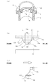
- FIG. 1 shows an embodiment of a gas generator formed using an igniter assembly 100.
- the gas generator is not limited to a gas generator used for an air bag, and may be used for a seat belt pretensioner, a curtain air bag, or various actuators. It may be The gas generator combines a diffuser shell 101 having a gas discharge port 104 with a closure shell 102 for closing the diffuser shell 101 to form a housing 103 in which the igniter assembly 100 is mounted. Be placed. Before the igniter assembly 100 is operated, the gas discharge port 104 is closed from the inside of the housing 103 by a sealing tape 115 made of aluminum.
- the gas generating agent 105 charged in the housing 103 is ignited and burned by the operation of the igniter 1 (see FIG. 2) included in the igniter assembly 100. For example, it generates combustion gas for inflating an air bag (bag body).
- an inner cylindrical member 108 provided with a plurality of transmission holes 107 in the peripheral wall is disposed at the center of the housing 103, and inside the inner cylindrical member 108, A space 109 for containing the igniter assembly 100 and the transfer charge 111 is formed, and a combustion chamber 110 for containing the gas generating agent 105 is formed on the radially outer side thereof.
- the gas generating agent 105 is supported by an under plate 116 formed in a substantially ring shape in the combustion chamber 110.
- the transfer charge 111 it is possible to use a gas generating agent which has a good ignitability and a combustion temperature higher than that of the gas generating agent 105.
- the combustion temperature of the transfer charge 111 is preferably in the range of 1700 to 3000.degree.
- a charge transfer agent 111 for example, a known one comprising nitroguanidine (34% by weight) and strontium nitrate (56% by weight) can be used.
- a known black powder (boron nitrate) may be used as a transfer agent.
- the gas generating agent 105 a gas generating agent having a relatively low combustion temperature can be used as the gas generating agent 105.
- the combustion temperature of the gas generating agent 105 is desirably in the range of 1000 to 1700 ° C. It is possible to use known products consisting of 41 wt%), basic copper nitrate (49 wt%) and binders and additives.
- the igniter assembly 100 is fixed below the inner cylindrical member 108.
- the igniter assembly 100 is fixed to the inner cylinder member 108 by caulking the open end 112 side of the inner cylinder member 108 and fixing the metal collar 2 (see FIG. 2) of the igniter assembly 100. It can be carried out.
- the inner cylindrical member 108 is connected to the closure shell 102 by welding or the like at the open end 112 on the side where the igniter assembly 100 is accommodated.
- a gas generating agent 105 is accommodated in the combustion chamber 110, and a filter 106 for collecting combustion residues contained in the combustion gas generated by the combustion of the gas generating agent 105 and cooling the combustion gas is provided outside the gas generation agent 105. It is arranged.
- the filter 106 is formed in a tubular shape using a laminated wire mesh or the like, and the outer peripheral surface thereof is disposed to face the inner peripheral surface of the housing 103. Desirably, a gap 113 serving as a gas flow path is formed between the outer peripheral surface of the filter 106 and the inner peripheral surface of the housing 103, whereby the entire use of the filter 106 is realized.
- the outer peripheral surface of the filter 106 is supported by a perforated cylindrical punching plate 114, and the radially outward expansion and the contact with the inner peripheral surface of the housing 103 are suppressed.
- the transfer charge 111 disposed in the vicinity thereof is ignited and burned, and the transfer hole formed in the inner cylindrical member 108 is the flame.
- the gas is injected into the combustion chamber 110 from 107.
- the gas generating agent 105 in the combustion chamber 110 is ignited and burned by this flame to generate a combustion gas.
- the combustion gas is purified and cooled while passing through the filter 106, breaks the seal tape 115 that blocks the gas discharge port 104, and is released from the gas discharge port 104 to the outside.
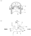
- FIG. 2 is a cross-sectional view of the igniter assembly 100 showing a bonding state in which the igniter 1 is bonded to a metal collar (a metal collar) 2 by a resin bonding portion 3 formed of a resin material. That is, in the igniter assembly 100, one metal igniter 2 is integrated with one electric igniter 1 at the resin joint 3.
- the igniter 1 has a pair of conductive pins 5 and burns the igniter with the ignition current supplied via the conductive pins 5.
- the electrically conductive pins 5 are kept in an electrically insulated state, and a bridge wire (not shown) is connected inside the cup 4 of the igniter 1.
- An igniter is accommodated in the inside of the cup 4, and the igniter is in contact with the bridge wire continuous with the conductive pins 5.
- the igniter is ignited and burned by the heat generation of the bridge wire to generate a combustion product.
- the upper surface of the cup 4 is cleaved, and the combustion product is released from the cleavage site.
- the transfer charge 111 disposed in the space 109 is exposed to the released combustion products.
- the metal collar 2 is formed in a substantially cylindrical shape, and a connector receiving portion 6 for receiving a connector (not shown) engaged with the conductive pin 5 of the igniter 1 and a resin filling in contact with the resin bonding portion 3 And 7 are included.
- a joint surface portion 8 annularly extending toward the center of the metal collar 2 (a position where the igniter 1 is disposed with respect to the metal collar 2) is provided on the resin filling portion 7 side of the connector receiving portion 6 At its tip end, the conductive pin of the igniter 1 forms a bore extending to the connector receiving portion 6 side.
- the metal collar 2 is provided with a protruding wall 10 standing annularly at the end portion on the resin filling portion 7 side and in the vicinity of the joint surface portion 8. In the bonded state shown in FIG. 2, the conductive pin 5 of the igniter 1 is located in the space surrounded by the protruding wall 10.
- the igniter 1 is integrated with the metal collar 2 by the resin joint 3.
- integration of the igniter 1 and the metal collar 2 by the resin bonding portion 3 will be described.
- the joint surface 8 and the projecting wall 10 of the metal collar 2 are covered and contacted by the resin material of the resin joint 3 which integrates the igniter 1 and the metal collar 2.
- Sealability by contact of the resin material utilizes molding shrinkage and post-shrinkage of the resin material.
- the resin material for integrating the igniter 1 and the metal collar 2 be injection molded between the two, so that the joint surface 8 and the projecting wall 10 of the metal collar 2 are covered during the injection molding. It is desirable to inject a resin material into the By injection molding, the resin material can cause desired molding shrinkage or post-shrinkage, and a pressing force can be applied to the joint surface 8 and the projecting wall 10 to enhance the sealing performance.
- the resin material of the resin bonding portion 3 one having a molding shrinkage of 1% or less is desirable, and one having 0.1 to 0.8% is particularly desirable.
- the molding shrinkage of the resin material is excessively large, the solidified resin is deformed, warped or sinks, and as a result, between the igniter 1 and the resin bonding portion 3 or the metal collar 2 and the resin bonding
- a resin material having an appropriate molding shrinkage ratio may be adopted in consideration of the occurrence of an undesirable gap or the like with the part 3.
- the resin material containing an inorganic filler such as glass fiber or inorganic filler is caused by the flow direction (MD) of the injection-molded resin and the direction (TD) perpendicular thereto due to the orientation of the inorganic filler. It is known that molding shrinkage rates differ. Therefore, when such a resin material is used, it is molded to such an extent that an undesirable gap is not generated at least between the igniter 1 and the resin bonding portion 3 or between the metal collar 2 and the resin bonding portion 3. Those having contraction rates (flow direction and vertical direction) are used.
- the bonding surface 8 and the protruding wall 10 are in the direction perpendicular to the flow direction of the resin material. It is preferable to have a surface that receives pressing force due to contraction of the resin material. With such a configuration, it is possible to effectively press the bonding surface portion 8 and the protruding wall 10 by the resin material that has been molded and shrunk while suppressing the contraction rate in the flow direction of the resin material. Therefore, in order to form the bonding state shown in FIG.
- the resin material forming the resin bonding portion 3 is formed in a cylindrical shape. It is desirable to inject in the flow direction along the axial direction (vertical direction in FIG. 2) of the metal collar 2 as described above.
- thermosetting resin can be used as a resin material of the resin bonding portion 3
- a thermoplastic resin is preferable in consideration of injection molding, and glass fibers and other inorganic filler materials are further preferably used. What contains is preferable.
- the resin preferably has a water absorption coefficient (same below) after immersion for 24 hours at 23 ° C. of preferably 0.005 to 0.5%, and more preferably 0.005 to 0.3%. Desirably, the pressure is 70 to 250 MPa, and more desirably 100 to 250 MPa. Further, it is desirable to use a resin having a linear expansion coefficient of 8 ⁇ 10 ⁇ 5 / ° C.
- the tensile strength is desirably 170 MPa or more, and preferably 250 MPa or less.
- a resin material nylon 612, polyarylate, polybutylene terephthalate, polyphenylene sulfide or liquid crystal polymer can be used. These resin materials may contain an inorganic filler such as glass fiber, glass filler or mineral, and in particular, 20 to 80% by mass of glass fiber is contained in polybutylene terephthalate, and 20 to 80% by mass in polyphenylene sulfide.
- liquid crystal polymer those containing 20 to 80% by mass of mineral are preferable.
- orientation of the glass fibers be adjusted along the stretching direction of the conductive pin 5 inserted into the resin material.
- the molding shrinkage rate in the thickness direction of the conductive pin 5 is increased, and the permeation of water between the conductive pin 5 and the resin material can be reliably prevented.
- the content of the inorganic filler material in each resin material is more preferably 20 to 50% by mass.
- the joint surface portion 8 is annularly formed so as to surround a part of the igniter 1 near the center of the internal space of the substantially cylindrical metal collar 2 in which the igniter 1 is disposed in the joined state.
- the first bonding groove 11 and the second bonding groove 12 are provided on the surface of the bonding surface 8 on the resin filling portion 7 side (hereinafter, referred to as “upper surface of the bonding surface 8”).
- FIG 3 shows a state of a cross-sectional perspective view when the metal collar 2 is cut at a cross section including the axis in the upper part (a), and the first bonding groove 11 and the second bonding groove 12 in the middle part (b)
- the geometrical structure of the first corner 11c and the second corner 12c provided in each joint groove is shown.
- the right side in the figure corresponds to the center side of the metal collar 2
- the left side corresponds to the peripheral side of the metal collar 2.
- the first bonding groove 11 is a groove which is opened on the upper surface of the bonding surface 8 and extends along the annular shape. That is, the first bonding groove 11 extends annularly in the circumferential direction of the igniter 1 in the bonding state shown in FIG.
- the opening width 11w of the first bonding groove 11 is constant over the entire circumference. As shown in FIG. 3B, the opening width is the distance between the two peripheral edges defining the opening of the first joint groove 11, that is, the inner peripheral edge 11a located on the center side of the metal collar 2; It is defined as the distance between the metal collar 2 and the outer peripheral edge 11 b located on the peripheral side of the metal collar 2.
- the inner peripheral edge 11a and the outer peripheral edge 11b intersect an imaginary line extending in the radial direction (direction shown by the arrow VL in FIG. 3A) around the igniter 1 in the bonded state all around its periphery Formed as. This means that geometrically, the inner peripheral edge 11a and the outer peripheral edge 11b do not have a portion extending parallel to the radial direction.
- the cross-sectional shape of the 1st joint groove 11 is a semicircle shape in general except the site
- a first corner portion 11 c formed of the upper surface of the bonding surface 8 and the inner wall surface of the first bonding groove 11 is formed on the entire periphery of the inner peripheral edge 11 a.
- an angle formed by the upper surface of the joint surface 8 and the inner wall surface of the first joint groove 11 (more specifically, in the cross section of FIG. 3C, the joint surface 8 and the first joint groove 11)
- the angle ⁇ 1) formed by tangents contacting each surface at the intersection with the inner wall surface is an angle relatively close to 90 degrees, and preferably an angle between 45 degrees and 90 degrees.
- the angle of the first corner portion 11c falls within this range, the forming process of the first bonding groove 11 in the metal collar 2 is easy, and the pressing force generated by the molding shrinkage of the resin material described later is preferably made.
- a pressure receiving surface for receiving pressure is formed.
- the second bonding groove 12 opens in the inner wall surface of the first bonding groove 11 so that the opening portion is located below the first corner 11 c and along the annular shape of the bonding surface 8. It is an extending groove. Specifically, the second bonding groove 12 is opened in the vicinity of the central bottom portion of the first bonding groove 11 in the cross section of the first bonding groove 11. The opening direction of the second bonding groove 12 coincides with the opening direction of the first bonding groove 11. The opening direction is a direction perpendicular to the opening surface (the surface defined by the inner peripheral edge and the outer peripheral edge) of each bonding groove. Therefore, the second bonding groove 12 annularly extends in the circumferential direction of the igniter 1 in the bonding state shown in FIG. 2 and overlaps the first bonding groove 11 in the depth direction of the first bonding groove 11. It is arranged.
- the opening width 12w of the second bonding groove 12 is smaller than the opening width 11w of the first bonding groove 11, and is constant over the entire circumference.
- the definition of the opening width is the same as that of the first bonding groove 11, and as shown in FIG. 3 (b), the distance between the two peripheral edges defining the opening of the second bonding groove 12, ie, metal collar It is defined as the distance between the inner peripheral edge 12 a located on the center side of 2 and the outer peripheral edge 12 b located on the peripheral side of the metal collar 2.
- the inner peripheral edge 12a and the outer peripheral edge 12b are formed to intersect the imaginary line extending in the radial direction indicated by the arrow VL in FIG.
- the inner peripheral edge 12a and the outer peripheral edge 12b do not have a portion extending parallel to the radial direction.
- the inner peripheral edge 12 a of the second joint groove 12 is located outside the inner peripheral edge 11 a of the first joint groove 11, that is, on the peripheral side of the metal collar 2.
- the cross-sectional shape of the second bonding groove 12 is generally semicircular as shown in FIG. 3 (b).
- a second corner 12c formed by the inner wall surface of the first bonding groove 11 and the inner wall surface of the second bonding groove 12 is formed on the entire periphery of the inner peripheral edge 12a.
- an angle formed by the inner wall surface of the first bonding groove 11 and the inner wall surface of the second bonding groove 12 (specifically, in the cross section of FIG. The angle ⁇ 2) made by tangents contacting each surface at the intersection of the wall surface and the inner wall surface of the second bonding groove 12 is an angle relatively close to 90 degrees, preferably at an angle between 90 degrees and 135 degrees. is there.
- the angle of the second corner 12c falls within this range, the forming process of the second joint groove 12 in the metal collar 2 is easy, and the pressing force generated by the molding shrinkage of the resin material described later is preferably made.
- a pressure receiving surface for receiving pressure is formed.
- the first bonding groove 11 and the second bonding groove 12 are disposed so as to overlap in the axial direction of the metal collar 2, and the opening directions thereof coincide. Therefore, the area of the bonding surface 8 can be made smaller than in the case where the first bonding groove 11 and the second bonding groove 12 are arranged side by side in the radial direction indicated by the arrow VL. The radial dimension can be made compact.
- the metal collar 2 is arranged along the axial direction of the metal collar 2.
- the resin material injected into the internal space of the metal collar 2 shrinks toward the center side of the metal collar 2 after entering the first joint groove 11 and the second joint groove 12. Therefore, the pressing force due to the contraction acts from the peripheral side to the central side of the metal collar 2.
- the first corner portion 11 c is formed on the inner peripheral edge 11 a of the first bonding groove 11
- the second corner portion 12 c is formed on the inner peripheral edge 12 a of the second bonding groove 12.
- each bonding groove at these corner portions (that is, the inner wall surface of the first bonding groove 11 at the first corner portion 11 and the inner wall surface of the second bonding groove 12 at the second bonding portion 12) 3 (c) in the direction from the peripheral side to the central side of the metal collar 2 (in the direction of the white arrow in FIG. 3C, and in the present embodiment, along the upper surface of the joint surface 8) Of ⁇ 1 and ⁇ 3) is preferably an angle of 45 degrees to 90 degrees.
- the inner wall surface of the bonding groove at each corner suitably receives the contraction force of the injection-molded resin material, and the sealability between the resin bonding portion 3 and the metal collar 2 is suitably made. It can be enhanced.
- the sealing performance can be extremely high, and the entry of moisture from the outside of the igniter assembly 100 is suitably prevented. can do.
- the projecting wall 10 is formed in a substantially cylindrical shape extending in the axial direction of the metal collar 2 and surrounds the igniter 1. As shown in FIG. 2, the projecting wall 10 is also covered with the resin bonding portion 3 which integrates the igniter 1 and the metal collar 2 with the inner peripheral surface, the outer peripheral surface, and the front end surface. By the contraction toward the center side of the metal collar 2 of the resin material, the protruding wall 10 is sandwiched in the thickness direction, and the bonding between the resin joint 3 and the metal collar 2 becomes more reliable.
- the compactness of the metal collar 2 is realized while keeping the sealing property by the resin material between the igniter 1 and the metal collar 2 relatively high. be able to.
- the machining becomes easy when cutting each joint groove in the metal collar 2.
- the corner portion on which the pressing force by the contraction of the injected resin material suitably acts as described above is each bonding groove It should just be formed in the inner periphery of.
- FIG. 4 shows the state of the cross-sectional perspective when the metal collar 2 used in the igniter assembly 100 is cut at a cross section including the axis in the upper part (a), and the first part in the lower part (b)
- the state which expanded the part of the joint surface part 8 in which the joint groove 21 and the 2nd joint groove 22 were provided is shown.
- the right side in the figure corresponds to the center side of the metal collar 2 and the left side corresponds to the peripheral side of the metal collar 2.
- the first bonding groove 21 is a groove which is opened on the upper surface of the bonding surface 8 and extends along the annular shape. That is, the first bonding groove 21 annularly extends in the circumferential direction of the igniter 1 in the bonding state shown in FIG.
- the opening width 21w of the first bonding groove 21 is constant over the entire circumference.
- the opening of the first joint groove 21 is defined by an inner peripheral edge 21 a located on the center side of the metal collar 2 and an outer peripheral edge 21 b located on the peripheral side of the metal collar 2.
- the inner peripheral edge 21a and the outer peripheral edge 21b are formed so as to intersect the imaginary line extending in the radial direction indicated by the arrow VL around the igniter 1 in the bonded state around the entire circumference thereof.
- the cross-sectional shape of the first bonding groove 21 is substantially rectangular except for the portion where the second bonding groove 22 is provided. Therefore, at the first corner 21c formed on the entire periphery of the inner peripheral edge 21a of the first bonding groove 21, the angle formed by the upper surface of the bonding surface 8 and the inner wall surface of the first bonding groove 21 is 90 degrees. Therefore, formation processing of the 1st junction groove 21 in metal collar 2 is easy, and the wall surface of the 1st corner 21c can catch suitably pressure pressure which arises by molding contraction of a resin material.
- the second bonding groove 22 is opened at the bottom surface of the first bonding groove 21 and is extended so as to follow the annular shape of the bonding surface 8 so that the opening portion is located below the first corner 21c. It is an existing ditch.
- the outer peripheral edge 22 b of the second bonding groove 22 matches the outer peripheral edge 21 b of the first bonding groove 21, and the inner peripheral edge 22 a is outer than the inner peripheral edge 21 a of the first bonding groove 21, That is, it is opened at the bottom of the first joint groove 21 so as to be located on the peripheral side of the metal collar 2.
- the opening direction of the second bonding groove 22 coincides with the opening direction of the first bonding groove 21.
- the opening direction is a direction perpendicular to the opening surface of each bonding groove. Therefore, the second bonding groove 22 annularly extends in the circumferential direction of the igniter 1 in the bonding state shown in FIG. 2, and overlaps the first bonding groove 21 in the depth direction of the first bonding groove 21. It is arranged.
- the opening width 22w of the second bonding groove 22 is smaller than the opening width 21w of the first bonding groove 21 and is constant over the entire circumference.
- the inner peripheral edge 22a and the outer peripheral edge 22b of the second bonding groove 22 are formed to intersect the imaginary line extending in the radial direction indicated by the arrow VL in the entire circumference thereof.
- the cross-sectional shape of the second bonding groove 22 is rectangular like the first bonding groove 21. Therefore, at the second corner 22c formed on the entire periphery of the inner peripheral edge 22a of the second bonding groove 22, the angle formed by the inner wall surface (bottom surface) of the first bonding groove 21 and the inner wall surface of the second bonding groove 22 is It will be 90 degrees. Therefore, the forming process of the 2nd junction slot 22 in metal collar 2 is easy, and the wall surface of the 2nd corner 22c can catch suitably the pressure which arises by the molding shrinkage of the resin material.
- the first joint groove 21 and the second joint groove 22 are arranged in the axial direction of the metal collar 2 in the joint surface portion 8 so as to overlap each other. Match. Therefore, the radial dimension of the metal collar 2 can be made compact.
- the resin material injected to integrate the igniter 1 through the resin bonding portion 3 with respect to the metal collar 2 in which two bonding grooves are arranged in an overlapping manner as described above is a first bonding groove. After entering the joint groove 11 and the second joint groove 12, it shrinks toward the center side of the metal collar 2. Therefore, the pressing force due to the contraction acts on the first corner 21c and the second corner 22c, and the sealability between the resin joint 3 and the metal collar 2 is suitably enhanced. Furthermore, since two such corner portions are arranged in the joint surface portion 8, the sealing performance can be extremely high, and the entry of moisture from the outside of the igniter assembly 100 is suitably prevented. can do.
- the first joint groove and the second joint groove are referred to by 31 and 32, respectively.
- the inner peripheral edge, the outer peripheral edge, the first corner portion, and the opening width of the first bonding groove 31 are respectively referred to by 31a, 31b, 31c, and 31w, and the inner peripheral edge, the outer peripheral edge, and the second angle of the second bonding groove 32.
- the portions and the opening widths are referred to by 32a, 32b, 32c and 32w, respectively.
- the first bonding groove 31 is a groove which is opened on the upper surface of the bonding surface 8 and extends along the annular shape.
- the inner peripheral edge 31a and the outer peripheral edge 31b are formed so as to intersect the imaginary line extending in the radial direction indicated by the arrow VL around the igniter 1 in the bonded state all around their circumferences.
- the second bonding groove 32 opens in the inner wall surface (bottom surface) of the first bonding groove 31 and follows the annular shape of the bonding surface portion 8 such that the opening portion is located below the first corner portion 31c. Is an extending groove.
- the inner peripheral edge 32a and the outer peripheral edge 32b are formed to intersect the imaginary line extending in the radial direction indicated by the arrow VL, with the igniter 1 in the joined state as the center around the entire circumference thereof. .
- both the first bonding groove 31 and the second bonding groove 32 are formed to have a rectangular cross section.
- the outer peripheral edge 32 b of the second bonding groove 32 coincides with the outer peripheral edge 31 b of the first bonding groove 31, and the inner peripheral edge 32 a of the second bonding groove 32 coincides with the inner peripheral edge 31 a of the first bonding groove 31.
- the second bonding groove 32 is open at the bottom of the first bonding groove 31. Therefore, the opening width 31w of the first bonding groove 31 and the opening width 32w of the second bonding groove 32 coincide with each other.
- the groove width of the second bonding groove 32 other than the opening is wider than the opening width 32 w.
- the angles of the first corner 31c and the second corner 32c are both 90 degrees, so that the wall surface of each corner suitably receives the pressing force generated by the molding shrinkage of the resin material. it can.
- the first bonding groove 31 is formed in a rectangular shape in cross section
- the second bonding groove 32 is formed in a semicircular shape in cross section.
- the outer peripheral edge 32b of the second bonding groove 32 coincides with the outer peripheral edge 31b of the first bonding groove 31, and the inner peripheral edge 32a of the second bonding groove 32 is outside the inner peripheral edge 31a of the first bonding groove 31, ie,
- a second bonding groove 32 is opened at the bottom of the first bonding groove 31 so as to be located on the peripheral side of the metal collar 2.
- the angle of the first corner portion 31c is 90 degrees, and the angle of the second corner portion 32c is close to 90 degrees, whereby the pressing force generated by the molding shrinkage of the resin material is Preferably, the wall surface of each corner can be received.
- the cross section of the first bonding groove 31 is formed in a fan shape (quarter circle shape), and the cross section of the second bonding groove 32 is formed in a rectangular shape.
- the outer peripheral edge 32b of the second bonding groove 32 is located inside the outer peripheral edge 31b of the first bonding groove 31, that is, on the center side of the metal collar 2, and the inner peripheral edge 32a of the second bonding groove 32 is the first.
- the second bonding groove 32 is opened on the inner wall surface of the first bonding groove 31 so as to be located outside the inner peripheral edge 31 a of the bonding groove 31, that is, on the peripheral side of the metal collar 2.
- the angle of the first corner portion 31c is 90 degrees, and the angle of the second corner portion 32c is close to 90 degrees, whereby the pressing force generated by the molding shrinkage of the resin material is Preferably, the wall surface of each corner can be received.
- igniter 2 metal collar 3: resin joint portion 8: joint surface portion 10: projecting wall 11, 21, 31: first joint groove 11 a, 12 a, 21 a, 22 a, 31 a, 32 a: inner peripheral edge 11 b, 12 b, 21b, 22b, 31b, 32b: outer peripheral edge 11c, 21c, 31c: first corner 12, 22, 32: second joint groove 12c, 22c, 32c: second corner 100: igniter assembly 103: housing 104 : Gas outlet 105: Gas generating agent
Landscapes
- Engineering & Computer Science (AREA)
- Chemical & Material Sciences (AREA)
- Physics & Mathematics (AREA)
- Fluid Mechanics (AREA)
- Mechanical Engineering (AREA)
- Organic Chemistry (AREA)
- Chemical Kinetics & Catalysis (AREA)
- General Engineering & Computer Science (AREA)
- Air Bags (AREA)
Priority Applications (4)
| Application Number | Priority Date | Filing Date | Title |
|---|---|---|---|
| DE112018006205.8T DE112018006205B4 (de) | 2017-12-05 | 2018-10-23 | Zünderanordnung und Gasgenerator |
| CN201880077599.5A CN111433083B (zh) | 2017-12-05 | 2018-10-23 | 点火器组装体及气体发生器 |
| KR1020207014849A KR102572679B1 (ko) | 2017-12-05 | 2018-10-23 | 점화기 조립체 및 가스 발생기 |
| US16/769,746 US10976139B2 (en) | 2017-12-05 | 2018-10-23 | Igniter assembly and gas generator |
Applications Claiming Priority (2)
| Application Number | Priority Date | Filing Date | Title |
|---|---|---|---|
| JP2017-233755 | 2017-12-05 | ||
| JP2017233755A JP6954520B2 (ja) | 2017-12-05 | 2017-12-05 | 点火器組立体、及びガス発生器 |
Publications (1)
| Publication Number | Publication Date |
|---|---|
| WO2019111567A1 true WO2019111567A1 (ja) | 2019-06-13 |
Family
ID=66751488
Family Applications (1)
| Application Number | Title | Priority Date | Filing Date |
|---|---|---|---|
| PCT/JP2018/039386 Ceased WO2019111567A1 (ja) | 2017-12-05 | 2018-10-23 | 点火器組立体、及びガス発生器 |
Country Status (6)
| Country | Link |
|---|---|
| US (1) | US10976139B2 (enExample) |
| JP (1) | JP6954520B2 (enExample) |
| KR (1) | KR102572679B1 (enExample) |
| CN (1) | CN111433083B (enExample) |
| DE (1) | DE112018006205B4 (enExample) |
| WO (1) | WO2019111567A1 (enExample) |
Families Citing this family (3)
| Publication number | Priority date | Publication date | Assignee | Title |
|---|---|---|---|---|
| DE102019134264A1 (de) * | 2019-12-13 | 2021-06-17 | Zf Airbag Germany Gmbh | Gasgenerator insbesondere für ein fahrzeugsicherheitssystem |
| JP7495306B2 (ja) * | 2020-09-11 | 2024-06-04 | 株式会社ダイセル | 点火装置組立体及び点火装置 |
| JP2024076039A (ja) | 2022-11-24 | 2024-06-05 | 日本化薬株式会社 | ガス発生器 |
Citations (4)
| Publication number | Priority date | Publication date | Assignee | Title |
|---|---|---|---|---|
| JP2004293835A (ja) * | 2003-03-26 | 2004-10-21 | Daicel Chem Ind Ltd | 点火器組立体 |
| JP3134281U (ja) * | 2007-05-29 | 2007-08-09 | 日本化薬株式会社 | 点火器組立体及びガス発生器 |
| JP3134430U (ja) * | 2007-05-30 | 2007-08-16 | 日本化薬株式会社 | 点火器組立体およびこれを備えたガス発生器 |
| KR20150026782A (ko) * | 2014-06-27 | 2015-03-11 | 유승열 | 화학기계적 연마장치용 리테이너 링 및 제조방법 |
Family Cites Families (49)
| Publication number | Priority date | Publication date | Assignee | Title |
|---|---|---|---|---|
| US3170027A (en) | 1962-01-03 | 1965-02-16 | Westinghouse Electric Corp | Treated cellulosic insulation and electrical apparatus embodying the same |
| DE3921472C1 (en) * | 1989-06-30 | 1990-11-15 | Bayern-Chemie Gesellschaft Fuer Flugchemische Antriebe Mbh, 8261 Aschau, De | Device for gas generator - in which gas for inflating cushion for protecting travellers in vehicle crash can take two routes to gas outlet |
| US5487559A (en) | 1994-09-13 | 1996-01-30 | Trw Inc. | Air bag inflator with pressure sensor |
| US5533754A (en) | 1995-05-31 | 1996-07-09 | Trw Vehicle Safety Systems Inc. | Air bag inflator |
| JPH1159314A (ja) * | 1997-08-12 | 1999-03-02 | Daicel Chem Ind Ltd | エアバッグ用ガス発生器 |
| US6412815B1 (en) * | 1998-09-28 | 2002-07-02 | Daicel Chemical Industries, Ltd. | Gas generator for air bag and air bag device |
| EP1518764B1 (en) | 1998-09-28 | 2011-09-28 | Daicel Chemical Industries, Ltd. | Gas generator for an airbag and air bag apparatus |
| JP3220443B2 (ja) * | 1998-11-30 | 2001-10-22 | ダイセル化学工業株式会社 | エアバッグ用ガス発生器及びエアバッグ装置 |
| WO2000048868A1 (en) | 1999-02-16 | 2000-08-24 | Daicel Chemical Industries, Ltd. | Gas generator for multi-stage air bag and air bag device |
| US6508175B1 (en) | 2000-10-31 | 2003-01-21 | Special Devices, Inc. | Pyrotechnic initiator for use in high pressure environments |
| DE20020103U1 (de) | 2000-11-27 | 2001-04-05 | TRW Airbag Systems GmbH & Co. KG, 84544 Aschau | Pyrotechnischer Gasgenerator |
| US6857658B2 (en) * | 2001-03-15 | 2005-02-22 | Daicel Chemical Industries, Ltd. | Gas generator for air bag and air bag apparatus |
| WO2002088619A1 (en) * | 2001-04-27 | 2002-11-07 | Daicel Chemical Industries, Ltd. | Initiator assembly and gas generator using the same |
| CN1304224C (zh) * | 2001-08-09 | 2007-03-14 | 日本化药株式会社 | 气体发生器 |
| JP4021178B2 (ja) | 2001-11-21 | 2007-12-12 | ダイセル化学工業株式会社 | イニシエータ組立体 |
| US6820556B1 (en) * | 2001-11-21 | 2004-11-23 | Daicel Chemical Industries, Ltd. | Initiator assembly |
| JP2003226222A (ja) | 2001-11-30 | 2003-08-12 | Daicel Chem Ind Ltd | インフレータ |
| US7134689B2 (en) | 2001-11-30 | 2006-11-14 | Daicel Chemical Industries, Ltd. | Inflator |
| KR100427359B1 (ko) * | 2002-02-25 | 2004-04-13 | 삼성전기주식회사 | 차량용 콤팩트디스크 플레이어의 로딩장치 |
| US20040251667A1 (en) * | 2003-03-26 | 2004-12-16 | Hiroshi Harada | Ignitor assembly |
| US7192054B2 (en) * | 2003-12-11 | 2007-03-20 | Autoliv Asp, Inc. | Locking initiator assembly for an airbag inflator device |
| JP4622605B2 (ja) * | 2005-03-18 | 2011-02-02 | タカタ株式会社 | 点火器組立体、インフレータ、エアバッグ装置及びシートベルト装置 |
| US20070001439A1 (en) * | 2005-06-16 | 2007-01-04 | Daicel Chemical Industries, Ltd. | Gas generator for air bag |
| US7510210B2 (en) * | 2005-08-08 | 2009-03-31 | Daicel Chemical Industries, Ltd. | Air bag module |
| US7854201B2 (en) * | 2005-11-08 | 2010-12-21 | Daicel Chemical Industries, Ltd. | Igniter assembly |
| US7905516B2 (en) * | 2006-05-19 | 2011-03-15 | Tk Holdings Inc. | Airbag module with integrated gas generation |
| JP2008062685A (ja) * | 2006-09-05 | 2008-03-21 | Daicel Chem Ind Ltd | 点火器組立体を備えた装置 |
| US7591483B2 (en) * | 2006-11-06 | 2009-09-22 | Daicel Chemical Industries, Ltd. | Gas generator for restraining device for vehicle |
| JP4916868B2 (ja) * | 2006-12-20 | 2012-04-18 | 株式会社ダイセル | 電気的な着火を利用する装置の組立方法 |
| AT10051U1 (de) | 2007-06-26 | 2008-08-15 | Hirtenberger Automotive Safety | Zündeinrichtung für einen pyrotechnischen gasgenerator |
| EP2342102B1 (de) * | 2008-09-30 | 2017-11-22 | TRW Airbag Systems GmbH | Gasgenerator, verfahren zu seiner herstellung sowie modul mit gasgenerator |
| JP5324930B2 (ja) * | 2009-01-15 | 2013-10-23 | 株式会社ダイセル | 車両の人員拘束装置用ガス発生器 |
| JP5450306B2 (ja) * | 2010-07-29 | 2014-03-26 | 株式会社ダイセル | ガス発生器 |
| US9079808B2 (en) * | 2010-10-06 | 2015-07-14 | Nippon Kayaku Kabushiki Kaisha | Gas generator, gas generator holder and method for manufacturing gas generator holder |
| JP5595237B2 (ja) * | 2010-11-12 | 2014-09-24 | 株式会社ダイセル | 点火器組立体 |
| JP5921232B2 (ja) * | 2012-02-06 | 2016-05-24 | 株式会社ダイセル | ガス発生器 |
| JP5873373B2 (ja) * | 2012-04-02 | 2016-03-01 | 株式会社ダイセル | ガス発生器 |
| JP6031250B2 (ja) * | 2012-04-23 | 2016-11-24 | 株式会社ダイセル | ガス発生器 |
| JP5944270B2 (ja) * | 2012-08-29 | 2016-07-05 | 日本化薬株式会社 | ガス発生器 |
| JP5985950B2 (ja) * | 2012-10-04 | 2016-09-06 | 株式会社ダイセル | ガス発生器とその組立方法 |
| JP6084096B2 (ja) * | 2013-03-29 | 2017-02-22 | 日本化薬株式会社 | ガス発生器 |
| JP6009997B2 (ja) * | 2013-06-21 | 2016-10-19 | 株式会社ダイセル | 人員拘束装置用ガス発生器 |
| JP6483949B2 (ja) * | 2014-01-09 | 2019-03-13 | 株式会社ダイセル | ガス発生器 |
| JP6407759B2 (ja) * | 2015-02-17 | 2018-10-17 | 株式会社ダイセル | パイロ式アクチュエータ機構、注射器、及び点火器組立体 |
| JP6504963B2 (ja) * | 2015-08-05 | 2019-04-24 | 株式会社ダイセル | 筒状ハウジング開口部の閉塞構造とガス発生器 |
| JP6675255B2 (ja) * | 2016-04-12 | 2020-04-01 | 株式会社ダイセル | ガス発生器 |
| US10814828B2 (en) * | 2016-08-29 | 2020-10-27 | Daicel Corporation | Gas generator |
| DE102017109209A1 (de) | 2017-04-28 | 2018-10-31 | Trw Airbag Systems Gmbh | Anzünderträger, baugruppe, gasgenerator sowie verfahren zur herstellung eines gasgenerators |
| US10549038B2 (en) * | 2017-06-29 | 2020-02-04 | Daicel Corporation | Syringe |
-
2017
- 2017-12-05 JP JP2017233755A patent/JP6954520B2/ja active Active
-
2018
- 2018-10-23 DE DE112018006205.8T patent/DE112018006205B4/de active Active
- 2018-10-23 WO PCT/JP2018/039386 patent/WO2019111567A1/ja not_active Ceased
- 2018-10-23 US US16/769,746 patent/US10976139B2/en active Active
- 2018-10-23 KR KR1020207014849A patent/KR102572679B1/ko active Active
- 2018-10-23 CN CN201880077599.5A patent/CN111433083B/zh active Active
Patent Citations (4)
| Publication number | Priority date | Publication date | Assignee | Title |
|---|---|---|---|---|
| JP2004293835A (ja) * | 2003-03-26 | 2004-10-21 | Daicel Chem Ind Ltd | 点火器組立体 |
| JP3134281U (ja) * | 2007-05-29 | 2007-08-09 | 日本化薬株式会社 | 点火器組立体及びガス発生器 |
| JP3134430U (ja) * | 2007-05-30 | 2007-08-16 | 日本化薬株式会社 | 点火器組立体およびこれを備えたガス発生器 |
| KR20150026782A (ko) * | 2014-06-27 | 2015-03-11 | 유승열 | 화학기계적 연마장치용 리테이너 링 및 제조방법 |
Also Published As
| Publication number | Publication date |
|---|---|
| DE112018006205B4 (de) | 2025-01-30 |
| US10976139B2 (en) | 2021-04-13 |
| US20200386525A1 (en) | 2020-12-10 |
| KR20200090781A (ko) | 2020-07-29 |
| DE112018006205T5 (de) | 2020-09-03 |
| JP6954520B2 (ja) | 2021-10-27 |
| CN111433083A (zh) | 2020-07-17 |
| KR102572679B1 (ko) | 2023-08-31 |
| CN111433083B (zh) | 2022-01-28 |
| JP2019099022A (ja) | 2019-06-24 |
Similar Documents
| Publication | Publication Date | Title |
|---|---|---|
| JP4021178B2 (ja) | イニシエータ組立体 | |
| US6820556B1 (en) | Initiator assembly | |
| CN1140765C (zh) | 点火器总成 | |
| WO2019111567A1 (ja) | 点火器組立体、及びガス発生器 | |
| EP1541429B1 (en) | Gas generator | |
| US20130276664A1 (en) | Gas generator | |
| US9455519B2 (en) | Pole member for a pyrotechnical igniter of an inflator, igniter, inflator and airbag module comprising said pole member | |
| JP6040221B2 (ja) | 成形済みeld消散装置を有する起動装置 | |
| CN101772689A (zh) | 点火装置以及气囊用气体产生装置及安全带预紧器用气体产生装置 | |
| US20200061566A1 (en) | Gas generator and container | |
| US20070186797A1 (en) | Gas generator | |
| US7793974B2 (en) | Gas generator for human body restraining apparatus of vehicle | |
| CN116853171A (zh) | 气体发生器 | |
| US20190201829A1 (en) | Filter for gas generator and gas generator | |
| WO1998021073A1 (en) | Gas generator for air bag | |
| WO2021054117A1 (ja) | 点火器組立体及び点火器組立体の組立方法 | |
| CN116917167A (zh) | 点火器组装体以及气体发生器 | |
| US20250206254A1 (en) | Igniter Assembly and Gas Generation Device | |
| CN111655552A (zh) | 用于安全系统的气体发生器 | |
| JP2018076011A (ja) | ガス発生器 | |
| US20250091544A1 (en) | Gas generator | |
| RU2329392C1 (ru) | Способ изготовления кольцевого пленочного воспламенителя |
Legal Events
| Date | Code | Title | Description |
|---|---|---|---|
| 121 | Ep: the epo has been informed by wipo that ep was designated in this application |
Ref document number: 18886500 Country of ref document: EP Kind code of ref document: A1 |
|
| 122 | Ep: pct application non-entry in european phase |
Ref document number: 18886500 Country of ref document: EP Kind code of ref document: A1 |