WO2019107327A1 - 吸収性物品の包装体及び吸収性物品の包装体の製造方法 - Google Patents
吸収性物品の包装体及び吸収性物品の包装体の製造方法 Download PDFInfo
- Publication number
- WO2019107327A1 WO2019107327A1 PCT/JP2018/043488 JP2018043488W WO2019107327A1 WO 2019107327 A1 WO2019107327 A1 WO 2019107327A1 JP 2018043488 W JP2018043488 W JP 2018043488W WO 2019107327 A1 WO2019107327 A1 WO 2019107327A1
- Authority
- WO
- WIPO (PCT)
- Prior art keywords
- sheet
- absorbent
- absorbent article
- package
- absorbent core
- Prior art date
- Legal status (The legal status is an assumption and is not a legal conclusion. Google has not performed a legal analysis and makes no representation as to the accuracy of the status listed.)
- Ceased
Links
Images



Classifications
-
- A—HUMAN NECESSITIES
- A61—MEDICAL OR VETERINARY SCIENCE; HYGIENE
- A61F—FILTERS IMPLANTABLE INTO BLOOD VESSELS; PROSTHESES; DEVICES PROVIDING PATENCY TO, OR PREVENTING COLLAPSING OF, TUBULAR STRUCTURES OF THE BODY, e.g. STENTS; ORTHOPAEDIC, NURSING OR CONTRACEPTIVE DEVICES; FOMENTATION; TREATMENT OR PROTECTION OF EYES OR EARS; BANDAGES, DRESSINGS OR ABSORBENT PADS; FIRST-AID KITS
- A61F13/00—Bandages or dressings; Absorbent pads
- A61F13/15—Absorbent pads, e.g. sanitary towels, swabs or tampons for external or internal application to the body; Supporting or fastening means therefor; Tampon applicators
- A61F13/551—Packaging before or after use
- A61F13/5513—Packaging before or after use packaging of feminine sanitary napkins
- A61F13/55135—Packaging before or after use packaging of feminine sanitary napkins before use
- A61F13/5514—Packaging before or after use packaging of feminine sanitary napkins before use each item packaged single
-
- A—HUMAN NECESSITIES
- A61—MEDICAL OR VETERINARY SCIENCE; HYGIENE
- A61F—FILTERS IMPLANTABLE INTO BLOOD VESSELS; PROSTHESES; DEVICES PROVIDING PATENCY TO, OR PREVENTING COLLAPSING OF, TUBULAR STRUCTURES OF THE BODY, e.g. STENTS; ORTHOPAEDIC, NURSING OR CONTRACEPTIVE DEVICES; FOMENTATION; TREATMENT OR PROTECTION OF EYES OR EARS; BANDAGES, DRESSINGS OR ABSORBENT PADS; FIRST-AID KITS
- A61F13/00—Bandages or dressings; Absorbent pads
- A61F13/15—Absorbent pads, e.g. sanitary towels, swabs or tampons for external or internal application to the body; Supporting or fastening means therefor; Tampon applicators
- A61F13/15577—Apparatus or processes for manufacturing
- A61F13/15707—Mechanical treatment, e.g. notching, twisting, compressing, shaping
- A61F13/15747—Folding; Pleating; Coiling; Stacking; Packaging
-
- A—HUMAN NECESSITIES
- A61—MEDICAL OR VETERINARY SCIENCE; HYGIENE
- A61F—FILTERS IMPLANTABLE INTO BLOOD VESSELS; PROSTHESES; DEVICES PROVIDING PATENCY TO, OR PREVENTING COLLAPSING OF, TUBULAR STRUCTURES OF THE BODY, e.g. STENTS; ORTHOPAEDIC, NURSING OR CONTRACEPTIVE DEVICES; FOMENTATION; TREATMENT OR PROTECTION OF EYES OR EARS; BANDAGES, DRESSINGS OR ABSORBENT PADS; FIRST-AID KITS
- A61F13/00—Bandages or dressings; Absorbent pads
- A61F13/15—Absorbent pads, e.g. sanitary towels, swabs or tampons for external or internal application to the body; Supporting or fastening means therefor; Tampon applicators
- A61F13/45—Absorbent pads, e.g. sanitary towels, swabs or tampons for external or internal application to the body; Supporting or fastening means therefor; Tampon applicators characterised by the shape
- A61F13/47—Sanitary towels, incontinence pads or napkins
-
- A—HUMAN NECESSITIES
- A61—MEDICAL OR VETERINARY SCIENCE; HYGIENE
- A61F—FILTERS IMPLANTABLE INTO BLOOD VESSELS; PROSTHESES; DEVICES PROVIDING PATENCY TO, OR PREVENTING COLLAPSING OF, TUBULAR STRUCTURES OF THE BODY, e.g. STENTS; ORTHOPAEDIC, NURSING OR CONTRACEPTIVE DEVICES; FOMENTATION; TREATMENT OR PROTECTION OF EYES OR EARS; BANDAGES, DRESSINGS OR ABSORBENT PADS; FIRST-AID KITS
- A61F13/00—Bandages or dressings; Absorbent pads
- A61F13/15—Absorbent pads, e.g. sanitary towels, swabs or tampons for external or internal application to the body; Supporting or fastening means therefor; Tampon applicators
- A61F13/45—Absorbent pads, e.g. sanitary towels, swabs or tampons for external or internal application to the body; Supporting or fastening means therefor; Tampon applicators characterised by the shape
- A61F13/47—Sanitary towels, incontinence pads or napkins
- A61F13/4704—Sanitary towels, incontinence pads or napkins having preferential bending zones, e.g. fold lines or grooves
-
- A—HUMAN NECESSITIES
- A61—MEDICAL OR VETERINARY SCIENCE; HYGIENE
- A61F—FILTERS IMPLANTABLE INTO BLOOD VESSELS; PROSTHESES; DEVICES PROVIDING PATENCY TO, OR PREVENTING COLLAPSING OF, TUBULAR STRUCTURES OF THE BODY, e.g. STENTS; ORTHOPAEDIC, NURSING OR CONTRACEPTIVE DEVICES; FOMENTATION; TREATMENT OR PROTECTION OF EYES OR EARS; BANDAGES, DRESSINGS OR ABSORBENT PADS; FIRST-AID KITS
- A61F13/00—Bandages or dressings; Absorbent pads
- A61F13/15—Absorbent pads, e.g. sanitary towels, swabs or tampons for external or internal application to the body; Supporting or fastening means therefor; Tampon applicators
- A61F13/53—Absorbent pads, e.g. sanitary towels, swabs or tampons for external or internal application to the body; Supporting or fastening means therefor; Tampon applicators characterised by the absorbing medium
- A61F13/534—Absorbent pads, e.g. sanitary towels, swabs or tampons for external or internal application to the body; Supporting or fastening means therefor; Tampon applicators characterised by the absorbing medium having an inhomogeneous composition through the thickness of the pad
Definitions
- the present invention relates to a package of an absorbent article such as a disposable diaper and a sanitary napkin, and a method of manufacturing the package.
- the present applicant has described that the longitudinally extending circumferential leak-proof groove integrating the surface sheet and the absorber is transversely provided between the left and right grooves constituting the circumferential leak-proof groove.
- unwrapping state of the individual wrapping body is provided by providing a center groove extending in a direction and arranging the individual folding line of the individual wrapping body at a specific position between the circumferential leakage preventing groove and the central groove
- it is difficult for wrinkles to enter the portion of the top sheet corresponding to the bent portion in the absorbent article Patent Document 1.
- the present invention is an absorbent article comprising a front sheet, a back sheet, and an absorbent core disposed between the two sheets, and having a longitudinal direction corresponding to the longitudinal direction of the wearer and a transverse direction orthogonal thereto.
- the absorbent article is folded with the top sheet inside along the laterally extending folds of the absorbent article.
- the absorbent core includes a plurality of sheet pieces including synthetic fibers, and the sheet pieces are disposed on at least the surface sheet side in the thickness direction of the absorbent core.
- the present invention comprises an upper sheet, a lower sheet, and an absorbent core disposed between the two sheets, and an absorbent having a longitudinal direction corresponding to the longitudinal direction of the wearer and a transverse direction orthogonal thereto. It is a manufacturing method of the package of the absorptive article by which the article is wrapped in the state where it was folded up.
- the present invention comprises a core forming step of collecting a plurality of sheet pieces containing synthetic fibers to form the absorbent core.
- the continuous article of the absorbent article is cut to form the absorbent article Forming an article.
- the present invention comprises the step of folding the absorbent article with the top sheet inside to fold the absorbent article so as to form a laterally extending fold of the absorbent article.
- the bent portion is formed by bending the portion of the absorbent core where the sheet piece is present.
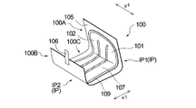
- FIG. 1 is a perspective view schematically showing an individual package of a sanitary napkin which is a preferred embodiment of the package of the absorbent article of the present invention.
- FIG. 2 is a perspective view which shows typically the state which removed the fastening tape in the individual packaging shown in FIG. 1, and opened it.
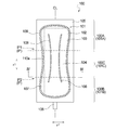
- FIG. 3 is a top view which shows typically the state which expand
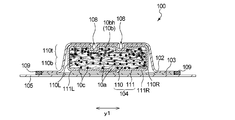
- FIG. 4 is a cross-sectional view schematically showing a cross section taken along line IV-IV of the individual package shown in FIG.
- FIG. 5 is a schematic side view schematically showing a preferred embodiment of a manufacturing apparatus for manufacturing the individual package shown in FIG. FIG.
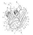
- FIG. 6 is a perspective view showing an absorber forming part of the manufacturing apparatus shown in FIG.
- FIG. 7 is a partially enlarged side view of a supply unit provided in the core forming unit shown in FIG.
- FIG. 8 is a schematic plan view of the individual package forming portion provided in the manufacturing apparatus shown in FIG.
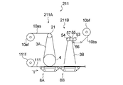
- FIG. 9 is a schematic side view schematically showing another embodiment of the core forming portion provided in the manufacturing apparatus shown in FIG.
- Patent Document 1 does not describe or suggest the use of a non-woven fabric piece as a constituent material of the absorber in order to prevent the occurrence of wrinkles on the surface sheet when the packaging state is released.
- the present invention relates to a package of an absorbent article which is less likely to be creased in the top sheet.
- the present invention relates to a method for producing a package of an absorbent article in which creases are less likely to occur on a surface sheet.
- the package of the absorbent article of the present invention is mainly used to absorb and hold body fluids excreted from the body such as urine and menstrual blood.
- Absorbent articles include, but are not limited to, for example, disposable diapers, sanitary napkins, incontinence pads, panty liners, etc., and widely include articles used for absorbing fluid discharged from the human body.
- the package of the absorbent article includes a package comprising a plurality of folded disposable diapers, or an individual package comprising one sanitary napkin or the like.
- the packaging body of the absorbent article of this invention is demonstrated using the individual packaging body 100 of the sanitary napkin 101 (Hereafter, it is also mentioned the napkin 101) which is one preferable embodiment.
- FIG. 1 shows a perspective view of the unopened individual package 100
- FIG. 2 shows a perspective view of the individual package 100 shown in FIG. 1 with the fastening tape 106 removed and unsealed.
- FIG. 3 shows a plan view of the surface sheet 102 side in a state in which the individual package 100 shown in FIG. 2 is developed
- FIG. 4 shows an IV-IV line of the individual package 100 in a state shown in FIG. A cross-sectional view is shown.
- the individual package body 100 has a longitudinal direction x1 corresponding to the front-rear direction of the wearer and a lateral direction y1 orthogonal to the longitudinal direction x1.
- the individual package 100 includes a napkin 101 having a liquid-permeable top sheet 102, a liquid-impermeable back sheet 103, and a liquid-retaining absorbent 104, and a napkin And a packaging material 105 for packaging 101.
- the individual packaging body 100 is configured such that the packaging material 105 is peelably adhered to the non-skin facing surface of the napkin 101 via the adhesive portion 107.
- the napkin 101 is folded with the top sheet 102 inside along the fold IP extending in the lateral direction y1.
- the bending portion IP includes a first bending portion IP1 and a second bending portion IP2 which are separated from each other in the longitudinal direction x1 of the napkin 101 and extend in the lateral direction y1.
- the individual package body 100 is arranged from the central region 100C located between the first bent portion IP1 and the second bent portion IP2, and from the first bent portion IP1 and the second bent portion IP2, respectively. It is divided into a first fold area 100A and a second fold area 100B extending outward in the longitudinal direction x1.
- the first fold area 100A and the second fold area 100B are sequentially stacked on the central area 100C in the thickness direction Z, and the central area 100C is a lower layer and the second fold area 100B is an upper layer.
- the first fold area 100A is a middle layer disposed between the two layers 100C and 100B.
- the individual package 100 is sealed by the fastening tape 106 in the unopened state.
- the napkin 101 and the packaging material 105 have a long shape in the longitudinal direction x1 when the individual package 100 is unfolded, and the longitudinal direction coincides with the longitudinal direction x1 and is orthogonal to the longitudinal direction.
- the width direction coincides with the horizontal direction y1.
- the longitudinal direction x1 is also a direction extending from the ventral side of the wearer to the dorsal side via the crotch.
- the skin-facing surface is the surface (relatively close to the skin of the wearer) of the napkin 101 and its constituent members (for example, the absorber 104) that is directed toward the skin of the wearer in the worn state
- the non-skin facing surface is a surface (a side relatively distant from the skin of the wearer) of the napkin 101 and its constituent members that is directed to the opposite side to the skin side of the wearer in the wearing state.
- wearing state as used herein means a state in which the normal proper wearing position (the correct wearing position of the absorbent article) is maintained, and includes the case where the absorbent article is deviated from the wearing position. Absent. In the individual package 100 of the napkin 101, the thickness direction will be described as the z direction.
- the packaging material 105 packages the whole of the napkin 101 as shown in FIG. 1 and FIG. 2, and as shown in FIG. 3, the area of the packaging material 105 in plan view is in plan view of the napkin 101. It is larger than the area at the time.
- the packaging material 105 has a rectangular shape in a plan view as shown in FIG. 3, and the longitudinal direction of the packaging material 105 matches the longitudinal direction x1 of the napkin 101.
- the napkin 101 is fixed to the inside of the packaging material 105 via an adhesive portion 107 disposed on the non-skin opposing surface of the napkin 101.
- the adhesive section 107 also functions as a displacement prevention section for fixing the napkin 101 to clothes when the napkin 101 is worn.
- the arrangement pattern of the adhesive unit 107 can be set as appropriate in consideration of the displacement prevention function and the like.
- the packaging material 105 wraps the entire napkin 101 by being folded along with the napkin 101 along the fold portion IP.
- the packaging material 105 those generally used in absorbent articles such as panty liners and sanitary napkins can be used without particular limitation.
- the packaging material 105 for example, a film, a nonwoven fabric, or the like can be used.
- the napkin 101 is disposed between the top sheet 102 disposed on the skin side of the wearer, the back sheet 103 disposed on the non-skin side of the wearer, and the sheets 102 and 103.
- the absorbent body 104 is provided.
- the absorbent body 104 has an absorbent core 110 and a liquid-permeable core wrap sheet 111 covering the absorbent core 110, as described later. Accordingly, it can be said that the napkin 101 includes the top sheet 102, the back sheet 103, and the absorbent core 110 disposed between the two sheets 102 and 103. As shown in FIG.
- the napkin 101 has a front area 101A disposed on the ventral side of the wearer, a rear area 101B disposed on the back side, and an excretory part area 101C located therebetween.
- the excretory part region 101 ⁇ / b> C corresponds to the central region 100 ⁇ / b> C in the individual package 100. That is, the excretory part region 101C is a portion sandwiched between the first bent portion IP1 and the second bent portion IP2.
- the front area 101A corresponds to the first folding area 100A of the package 100
- the rear area 101B corresponds to the second folding area 100B of the package 100.
- the shape of the absorbent article constituting the package of the present invention in plan view is not particularly limited.
- the napkin 101 is elongated in the longitudinal direction x1 and extends in the longitudinal direction x1. It is formed symmetrically with respect to the center line CL.
- the longitudinal direction x1 is also a direction parallel to the center line CL.
- the napkin 101 has a shape in which both sides along the longitudinal direction x1 are narrowed inward in the lateral direction y1 in the excretory part region 101C (the center of the longitudinal direction x1).
- the absorbent core 110 has a recess 108 recessed from the top sheet 102 side toward the back sheet 103 side.
- the napkin 101 has a recess 108 in which the top sheet 102 and the absorber 104 are integrally recessed on the back sheet 103 side. That is, in the concave portion 108, the surface sheet 102, the absorbent core 110, and the core wrap sheet 111 disposed therebetween are integrally recessed.
- the concave portion 108 is formed by applying a pressing process to the napkin 101 from the skin-facing surface, that is, the top sheet 102 side, to the back sheet 103 side.
- Examples of the pressing process include known embossing processes such as heat embossing and ultrasonic embossing. Due to the method of forming such a recess 108, at the bottom of the recess 108, the top sheet 102 and the absorber 104 can be heat-fused and integrated.
- the pattern of the plan view shape and the arrangement of the recess 108 is not limited to the shape extending in a plane view as shown in FIG. 3, for example, circular, oval, rectangular, triangular It may be in the form of an independent dot such as a star, a heart or the like.
- the depth of the concave portion 108 is not limited to one which is constant over the entire length in the longitudinal direction, and may be partially different, for example.
- the shape, arrangement and the like of the linear recess 108 are not limited to the illustrated form, and can be set in the same manner as what is called leak-proof groove etc. in this type of absorbent article, and the shape in plan view is straight and / or Each line may be a continuous line or a broken line.
- the top sheet 102 of the napkin 101 covers the entire skin-facing surface of the absorbent body 104.
- the back sheet 103 covers the entire non-skin facing surface of the absorber 104.
- the top sheet 102 and the back sheet 103 have their outer edges 109 joined together by a known bonding means such as an adhesive, heat seal, ultrasonic seal or the like.
- Each of the top sheet 102 and the back sheet 103 and the absorber 104 may be bonded by an adhesive.
- various kinds of materials conventionally used in absorbent articles such as sanitary napkins can be used without particular limitation.
- the surface sheet 102 a nonwoven fabric of a single layer or multilayer structure, an apertured film, or the like can be used.
- As the back sheet 103 a moisture-permeable resin film or the like can be used.
- the absorbent body 104 when the napkin 101 is worn, the absorbent body 104 has a long shape in the longitudinal direction x1 corresponding to the longitudinal direction of the wearer, and the longitudinal direction coincides with the longitudinal direction x1, and the longitudinal direction The orthogonal width direction coincides with the lateral direction y1.
- the absorbent body 104 has an absorbent core 110 and a liquid-permeable core wrap sheet 111 which covers the absorbent core 110.
- the core wrap sheet 111 is a single continuous sheet having a width twice to three times the length of the absorbent core 110 in the lateral direction y1. As shown in FIG.
- the core wrap sheet 111 covers the entire skin-facing surface of the absorbent core 110 and extends outward in the lateral direction y1 from both side edges 110R and 110L along the longitudinal direction x1 of the absorbent core 110.
- the extending portions 111R and 111L are rolled down below the absorbent core 110 to cover the entire non-skin facing surface of the absorbent core 110.
- the core wrap sheet may not be such a single sheet, for example, one skin side core wrap sheet covering the skin facing surface of the absorbent core 110, and the skin side.
- the core wrap sheet may be separate from the core wrap sheet, and may include two sheets with one non-skin side core wrap sheet covering the non-skin facing surface of the absorbent core 110.
- the absorbent core 110 has the recess 108 described above, as shown in FIG. That is, a portion corresponding to the concave portion 108 on the top sheet 102 side is recessed in a manner integrally with the top sheet 102 from the top sheet 102 side to the back sheet 103 side. Since the absorbent core 110 is recessed by the above-described recess 108, deflection can be suppressed at the time of mounting. Further, the absorbent core 110 can be densified by pushing the recess 108 deeply, and the liquid draw-in property can be improved.
- the absorbent core 110 includes a plurality of sheet pieces 10bh (hereinafter, also simply referred to as sheet pieces 10bh) containing synthetic fibers 10b, and the sheet pieces 10bh are disposed at least on the surface sheet 102 side. It is done.
- the sheet piece 10bh has a substantially uniform shape and size.
- Each sheet piece 10bh has a substantially rectangular shape as shown in FIG.
- the average length of each sheet piece 10bh is preferably 0.3 mm or more and 30 mm or less, more preferably 1 mm or more and 15 mm or less, and particularly preferably 2 mm or more and 10 mm or less.
- the average length indicates the average value of the lengths of the sides in the longitudinal direction when each sheet piece 10bh has a rectangular shape.
- each sheet piece 10bh has a square shape, it indicates the average value of the lengths of any one of the four sides.
- the average width of each sheet piece 10bh is preferably 0.1 mm or more and 10 mm or less, more preferably 0.3 mm or more and 6 mm or less, and particularly preferably 0.5 mm or more and 5 mm or less.
- the average width indicates the average value of the lengths of the sides in the short direction when each sheet piece 10bh has a rectangular shape.
- each sheet piece 10bh When each sheet piece 10bh has a square shape, it indicates the average value of the lengths of any one of the four sides.
- the average width of the sheet piece 10bh is 0.1 mm or more, it is easy to form a sparse structure in the absorber 104, and when it is 10 mm or less, it is difficult for the wearer to feel discomfort due to the absorber 104. It is hard to produce nonuniformity in absorption performance by the position in 104.
- the average thickness of each sheet piece 10bh is preferably 0.001 mm or more and 10 mm or less, and more preferably 0.01 mm or more and 5 mm or less.
- the absorbent core 110 contains the hydrophilic fiber 10a other than the sheet piece 10bh.
- a fiber material which forms absorptive core 110 conventionally, various things used for absorptive core 110 for absorptive articles can be used without restriction.
- the hydrophilic fibers 10a include pulp fibers, rayon fibers, cotton fibers and the like.
- the synthetic fiber 10 b include short fibers such as polyethylene, polypropylene and polyethylene terephthalate.
- the sheet piece 10bh is not particularly limited as long as it has a sheet shape, but a non-woven fabric is preferable.
- the absorbent core 110 may not include the hydrophilic fiber 10a as long as it has the sheet piece 10bh. However, when the absorbent core 110 includes the hydrophilic fiber 10a, the absorbent core 110 is hydrophilic to the sheet piece 10bh.
- the content ratio to the fibers 10a (the contained mass of the sheet piece 10bh / the contained mass of the hydrophilic fibers 10a) is not particularly limited, and may be appropriately adjusted according to the types of the sheet pieces 10bh and the hydrophilic fibers 10a.
- the synthetic fiber contained in the sheet piece 10bh is pet / polyethylene and the hydrophilic fiber 10a is cellulose
- 0.01 or more is preferable, 0.1 or more is more preferable, 100 or less is preferable, 10 or less is more preferable, 0.01 or more and 100 or less are preferable for the content mass ratio of the sheet piece 10bh and the hydrophilic fiber 10a. 0.1 or more and 10 or less are more preferable.
- the content of the sheet piece 10bh in the absorbent core 110 is preferably 1% by mass or more, more preferably 10% by mass or more, and preferably 100% by mass or less, with respect to the total mass of the absorbent core 110 in a dry state. Mass% or less is more preferable, 1 mass% or more and 100 mass% or less is preferable, and 10 mass% or more and 90 mass% or less is more preferable.
- the content of the hydrophilic fiber 10a in the absorbent core 110 is preferably 1% by mass or more, more preferably 10% by mass or more, and preferably 99% by mass or less based on the total mass of the absorbent core 110 in a dry state. 90 mass% or less is more preferable, 1 mass% or more and 99 mass% or less is preferable, and 10 mass% or more and 90 mass% or less is more preferable.
- the basis weight of the sheet piece 10bh in absorbent core 110 1 g / m 2 or more preferably, 20 g / m 2 or more, and preferably 1000 g / m 2 or less, more preferably 800g / m 2, 1g / m 2 or more and 1000 g / m 2 or less are preferable, and 20 g / m 2 or more and 800 g / m 2 or less are more preferable.
- the basis weight of the hydrophilic fibers 10a in the absorbent core 110 1 g / m 2 or more preferably, 20 g / m 2 or more, and preferably 1000 g / m 2 or less, more preferably 800g / m 2, 1g / m 2 or more and 1000 g / m 2 or less are preferable, and 20 g / m 2 or more and 800 g / m 2 or less are more preferable.
- the absorbent core 110 includes absorbent particles 10c in addition to the sheet piece 10bh and the hydrophilic fibers 10a.
- the absorbent particles 10c include starch-based, cellulose-based, synthetic polymer-based, and superabsorbent polymer-based ones.
- the superabsorbent polymer for example, those comprising starch-acrylic acid (salt) graft copolymer, saponified starch-acrylonitrile copolymer, cross-linked product of sodium carboxymethyl cellulose, acrylic acid (salt) polymer, etc. It can be used.
- the content of the absorbent particles 10c in the absorbent core 110 is preferably 0% by mass or more, more preferably 1% by mass or more, and preferably 90% by mass or less with respect to the total mass of the absorbent core 110 in a dry state. 70 mass% or less is more preferable, 0 mass% or more and 90 mass% or less is preferable, and 1 mass% or more and 70 mass% or less is more preferable.
- the basis weight of the absorbent particles 10c in the absorbent core 110 0 g / m 2 or more preferably, 5 g / m 2 or more, and preferably 1000 g / m 2 or less, more preferably 800g / m 2, 0g / m 2 or more and 1000 g / m 2 or less are preferable, and 5 g / m 2 or more and 800 g / m 2 or less are more preferable.
- a deodorizer As a constituent member which constitutes absorptive core 110, a deodorizer, an antibacterial agent, etc. can also be used if needed.
- the core wrap sheet 111 include fibrous sheets such as tissue paper and liquid-permeable nonwoven fabric.
- the absorbent core 110 is composed of a first layer 110t including a mixed fiber material of hydrophilic fibers 10a and sheet pieces 10bh and absorbent particles 10c, and a first layer 110t. Also, it has the second layer 110b containing the fibrous material and the absorbent particles 10c, in which the existing density of the sheet piece 10bh is small.
- the existing density of the sheet piece 10bh is the number of sheet pieces 10bh per 1 cm 2 of arbitrary cross section parallel to the thickness direction Z of the absorbent core 110.
- the first layer 110 t is disposed on the top sheet 102 side
- the second layer 110 b is disposed on the back sheet 103 side.
- the sheet piece 10bh and the hydrophilic fiber 10a are respectively entangled with each other. That is, in the first layer 110t, the hydrophilic fiber is entangled and bonded to the sheet piece 10bh.
- the sheet piece 10bh is not present in the second layer 110b of the absorbent core 110 of the present embodiment, and only the hydrophilic fibers 10a and the absorbent particles 10c are provided. It is in a entangled state.
- the sheet piece 10bh having recoverability that easily returns to the original state is the surface sheet 102 side in the absorbent core 110, that is, valley fold Since the sheet is disposed on the side, when the napkin 101 is developed from the individually mounted state, a crease is less likely to occur on the surface of the surface sheet 102 corresponding to the bent portion IP of the napkin 101.
- the sheet piece 10bh is disposed only on the first layer 110t on the side of the top sheet 102 in the absorbent core 110, and the side of the back sheet 103 on the absorbent core 110, that is, the second layer 110b on the mountain fold side.
- the sheet piece 10bh does not exist in the second layer 110b, when the napkin 101 is spread while the hydrophilic fiber 10a in the second layer 110b maintains the folded form, wrinkles are generated by the effect of the sheet piece 10bh in the first layer 110t. It is hard to occur. Moreover, since it becomes difficult to generate a wrinkles by arrangement
- the synthetic fiber 10b contained in the absorbent core 110 is not contained in a single fiber disintegrated state, but is contained as a sheet piece 10bh of the intended size, the original The recovery ability to easily return to the state is very high, and the crease can be effectively suppressed. Further, since the sheet pieces 10bh of the intended size are dispersed, it is difficult to cause a feeling of foreign matter during use of the napkin 101, and body fluid can be absorbed at high speed.
- the existence density of the sheet piece 10bh in the first layer 110t of the absorbent core 110 is 1 piece / cm 2 or more from the viewpoint of making it difficult to generate creases in the napkin 101 after the unopened individual package 100 is opened.
- 5 pieces / cm 2 or more is more preferable, 500 pieces / cm 2 or less is preferable, 200 pieces / cm 2 or less is more preferable, 1 piece / cm 2 or more and 500 pieces / cm 2 or less is preferable, 5 pieces / cm Two or more and 200 pieces / cm 2 or less are more preferable.
- the existing density of the sheet piece 10bh in the second layer 110b of the absorbent core 110 is preferably 0 piece / cm 2 or more, more preferably 1 piece / cm 2 or more, and 500 pieces / cm 2 or less 200 pieces / cm 2 or less are more preferable, 0 piece / cm 2 or more and 500 pieces / cm 2 or less are preferable, and 20 pieces / cm 2 or more and 200 pieces / cm 2 or less are more preferable.
- FIG. 5 shows the overall configuration of a manufacturing apparatus 200 of one embodiment used to carry out the manufacturing method of the present embodiment.
- 6 shows a perspective view of the absorber forming part 210 of the manufacturing apparatus 200
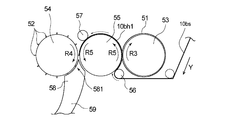
- FIG. 7 shows a partially enlarged side view of the supply part 5 for supplying the sheet piece 10bh provided in the absorber forming part 210. It is shown.
- a schematic plan view of the individual package forming portion 230 provided in the manufacturing apparatus is shown in FIG. Before describing the method of manufacturing the individual package 100, the manufacturing apparatus 200 will be described first.
- the manufacturing apparatus 200 includes, as shown in FIG. 5, an absorbent body forming portion 210 forming the absorbent body 104 and an absorbent article forming portion 220 forming the napkin 101, from the upstream side to the downstream side in the transport direction. And an individual package forming portion 230 that forms the individual package 100.
- the direction in which the belt-like synthetic fiber sheet 10bs including the synthetic fiber 10b and the continuous body 104r of the absorbent body are conveyed is the Y direction, a direction orthogonal to the conveyance direction, and the synthetic fiber sheet 10bs and the absorbent body
- the width direction of the continuous body 104r is taken as the X direction
- the thickness direction of the synthetic fiber sheet 10bs to be conveyed and the continuous body 104r of the absorbent body is taken as the Z direction.
- the first direction described later is a direction extending in the transport direction Y, and means a direction in which the angle formed with the transport direction Y is less than 45 degrees. In the present embodiment, the first direction coincides with the direction parallel to the transport direction Y.
- the 2nd direction mentioned later is a direction which intersects with the 1st direction.
- the second direction is a direction orthogonal to the first direction, and coincides with the direction parallel to the width direction of the synthetic fiber sheet 10bs to be conveyed and the absorber 104.
- the absorbent body forming part 210 is a core forming part 211 forming the absorbent core 110 and a core wrap sheet 111 covering the absorbent core 110 to form a continuous body 104r of the absorbent body.
- the core forming portion 211 is a defibrillation portion 2 for defibrillating the hydrophilic sheet 10as including the hydrophilic fiber 10a, and a duct for conveying the raw material of the absorber 104 on an air stream.
- a supply unit 5 for supplying a sheet piece 10 bh from the middle of the duct 3
- a rotary drum 4 disposed adjacent to the downstream side of the duct 3 and having an accumulation unit for accumulating the raw materials of the absorber 104
- a rotary drum A pressing belt 7 is disposed along the outer peripheral surface 4 f located on the opposite side of the duct 3 in 4.
- the defibrating unit 2 includes, as shown in FIG. 6, a defibrator 21 that defibrates the hydrophilic sheet 10as, and a casing 22 that covers the upper side of the defibrator 21.
- the defibrating unit 2 is a portion that supplies the disintegrated hydrophilic fibers 10 a that are the raw materials of the absorber 104 to the inside of the duct 3.
- the defibrating unit 2 also has a pair of feed rollers 23 and 23 for supplying the hydrophilic sheet 10as to the defibrating machine 21.
- the duct 3 extends from the defibrating unit 2 to the rotary drum 4, and the opening on the downstream side of the duct 3 is located in the space A of the rotary drum 4 maintained at a negative pressure. It covers the outer peripheral surface 4f.
- the duct 3 has a top plate 31 forming a top surface, a bottom plate 32 forming a bottom surface, and both side walls 33 and 34 forming both side surfaces.
- the absorber 104 is directed toward the outer peripheral surface 4 f of the rotary drum 4. Air flow is made to flow the raw materials of That is, the inside of the duct 3 is a flow passage 30.
- an absorbent particle dispersion pipe 36 for supplying the absorbent particles 10 c into the duct 3 is disposed.
- the absorbent particles 10 c are discharged from the dispersion port provided at the tip of the absorbent particle dispersion tube 36 via a device such as a screw feeder (not shown), and supplied to the inside of the duct 3. It is supposed to be The amount of the absorbent particles 10c supplied to the absorbent particle scattering tube 36 can be adjusted by an apparatus such as each screw feeder.
- the supply unit 5 includes a first cutter roller 53 having a plurality of cutter blades 51 for cutting in a first direction (X direction), and a plurality of cutters for cutting in a second direction (Y direction).
- a second cutter roller 54 having a cutter blade 52 and a receiving roller 55 disposed opposite to the first cutter roller 53 and the second cutter roller 54 are provided.
- the supply part 5 has the suction nozzle 58 which attracts
- the entire circumference of the first cutter roller 53 is continuous along the circumferential direction of the first cutter roller 53.
- a plurality of extending cutter blades 51, 51, 51,... are arranged in the axial direction (X direction) of the first cutter roller 53.
- the first cutter roller 53 is adapted to rotate in the direction of arrow R3 in response to power from a motor such as a motor. The distance between the cutter blades 51, 51, 51, ...
- the width of the sheet piece 10bh formed by cutting (the length in the short direction, the length in the X direction) Generally correspond to the More precisely, the synthetic fiber sheet 10bs is cut in a state of being shrunk in the width direction X depending on the tension at the time of sheet conveyance, so that the tension is released in the finished sheet piece 10bh.
- the width of the sheet piece 10bh may be wider than the interval between the blades 51, 51, 51,.
- a plurality of the cutter rollers 54 extend continuously along the axial direction of the second cutter roller 54 and over the entire width of the second cutter roller 54.
- the cutter blades 52, 52, 52,... are spaced in the circumferential direction of the second cutter roller 54.
- the second cutter roller 54 receives power from a motor such as a motor and rotates in the direction of arrow R4.
- the receiving roller 55 is a flat roller whose surface is flat as shown in FIG. 6 and FIG.
- the receiving roller 55 receives power from a motor such as a motor and rotates in the direction of the arrow R5.
- the supply unit 5 receives the receiving roller 55 and the first cutter roller 53 from the upstream side to the downstream side in the rotational direction (arrow R5 direction) on the opposing surface of the receiving roller 55.
- a free roller 56 for introducing a band-shaped synthetic fiber sheet 10bs, a first cutter roller 53 for cutting the band-shaped synthetic fiber sheet 10bs in a first direction, a plurality of cut in a first direction and extending in the first direction
- a strip roller 10bh1 (hereinafter, also referred to as a continuous sheet strip 10bh1) is cut in the second direction by a nip roller 57 introduced between the receiving roller 55 and the second cutter roller 54, and the strip continuous sheet 10bh1.
- the second cutter roller 54 is provided in order. Further, the supply unit 5 has a feed roller (not shown) for conveying the belt-like synthetic fiber sheet 10 bs, and the feed roller is a belt-like composite between the receiving roller 55 and the first cutter roller 53. Introduce the fiber sheet 10bs.
- the feed roller is configured to be rotated by a drive device such as a servomotor, for example. From the viewpoint of preventing the slip of the synthetic fiber sheet 10bs, the feed roller is not slippery by forming a groove extending in the axial direction in the surface over the entire circumference or applying a coating treatment for improving the frictional force over the entire circumference You may It may be difficult to slip by nipping with a nip roller feed roller.
- the supply unit 5 has a suction nozzle 58 for suctioning the sheet piece 10 bh formed by the second cutter roller 54.
- the suction nozzle 58 has its suction port 581 located below the second cutter roller 54, that is, the rotation direction of the second cutter roller 54 relative to the closest point of contact between the second cutter roller 54 and the receiving roller 55 (arrow R4 Direction) is located downstream. Further, the suction nozzle 58 has its suction port 581 extending over the entire width of the second cutter roller 54.
- the suction roller 581 of the receiving roller 55 and the second cutter roller 54 is arranged such that the suction port 581 of the suction nozzle 58 faces between the receiving roller 55 and the second cutter roller 54. It is preferable to arrange below. Then, from the viewpoint of further improving suction performance of the sheet piece 10bh, the suction port 581 of the suction nozzle 58 views the receiving roller 55 and the second cutter roller 54 from the side as shown in FIG. It is preferable to cover the outer surface of the second cutter roller 54 so that the arc length of the suction port 581 facing the second cutter roller 54 is longer than the arc length of the suction port 581 facing the.
- the suction nozzle 58 is connected to the top plate 31 side of the duct 3 via the supply pipe 59.
- the sheet piece 10 bh sucked from the suction port 581 of the suction nozzle 58 is supplied to the inside of the duct 3 from the middle of the duct 3 through the supply pipe 59.
- the connection position between the supply pipe 59 and the duct 3 is located between the defibrating unit 2 side and the rotary drum 4 side in the duct 3, and is located downstream of the absorbent particle scattering pipe 36 in the duct 3. ing.
- the connection position between the supply pipe 59 and the duct 3 is not limited to this.
- the connection position between the supply pipe 59 and the duct 3 may not be the top plate 31 side of the duct 3 but the bottom plate 32 side.
- the rotary drum 4 has a cylindrical shape, and has a member 40 forming the outer peripheral surface 4f, and a fixed drum main body 42 located inside the member 40.
- the member 40 forming the outer peripheral surface 4f receives power from a motor or the like and rotates about the horizontal axis in the direction of the arrow R1.
- the member 40 forming the outer peripheral surface 4 f has an accumulation recess 41 as an accumulation portion for accumulating the raw materials of the absorber to obtain the absorbent core 110.
- the accumulation recess 41 is continuously disposed all around the circumferential direction (2Y direction) of the rotary drum 4.
- the bottom surface of the accumulation recess 41 is formed of a porous member that functions as a suction hole for sucking the raw material of the absorber 104.
- the drum body 42 internally has a plurality of mutually independent spaces, and the pressure of each space is adjusted by the drive of an intake fan (not shown) connected to the rotary drum 4.
- the manufacturing apparatus 200 has three spaces A to C, and makes the suction force of the region corresponding to the space A stronger or weaker than the suction force of the region corresponding to the spaces B to C.
- the space A is maintained at a negative pressure.
- the pressing belt 7 is disposed along the outer peripheral surface 4 f adjacent to the downstream side of the position of the duct 3 and located in the space B of the rotating drum 4.
- the space B is set to a negative pressure or pressure zero (atmospheric pressure) weaker than the space A of the rotary drum 4.
- the presser belt 7 is an endless air-permeable or non-air-permeable belt, and is stretched over the rollers 71 and 72 so as to rotate along with the rotation of the rotary drum 4.
- the pressing belt 7 can hold the absorbent core continuum 110 r in the accumulation recess 41 in the accumulation recess 41 until it is transferred onto the vacuum conveyor 8.
- the covering portion 212 covers the continuous body 110r of the absorbent core while transporting the band-like core wrap sheet 111, and covers the continuous body 110r with the core wrap sheet 111, thereby forming a continuous body of the absorbent.
- the covering portion 212 has a vacuum conveyor 8 and a folding guide plate (not shown) disposed above the vacuum conveyor 8.
- the vacuum conveyor 8 is disposed below the rotary drum 4 and is disposed on the outer circumferential surface 4 f located in the space C set to a weak positive pressure or zero pressure (atmospheric pressure) of the rotary drum 4.
- the vacuum conveyor 8 is opposed to an endless air-permeable belt 83 stretched over the drive roller 81 and the driven rollers 82 and 82 and an outer peripheral surface 4 f located in the space C of the rotary drum 4 with the air-permeable belt 83 interposed therebetween. And a vacuum box 84 arranged at a position.
- a band-shaped core wrap sheet 111 made of tissue paper, liquid-permeable nonwoven fabric or the like is introduced.
- the folding guide plate is a member that folds back the extending portions 111R and 111L along the transport direction of the strip-shaped core wrap sheet 111 transported by the vacuum conveyor 8 in the width direction.
- the absorber cut portion 213 is disposed downstream of the folding guide plate.
- the absorber cut portion 213 includes a cutter roll 213a having a plurality of cutter blades on the circumferential surface, and an anvil roll 213b having a smooth circumferential surface for receiving the cutting cutter blade.
- the interval between cutter blades adjacent in the circumferential direction of the cutter roll 213a corresponds to the length in the transport direction (longitudinal length) of the absorber 104 formed by cutting.
- the absorbent article forming unit 220 supplies the surface sheet 102 to one surface side of the absorber 104 from the upstream side to the downstream side in the transport direction, as shown in FIG.
- the part 224 and the napkin cut part 225 which cuts the continuous body 101r of a napkin to form each napkin 101 are provided in order.
- the top sheet supply unit 221 has an introduction roll 221 f for introducing the strip-shaped top sheet 102 supplied from the raw fabric roll 2 f to one side of the absorbent body 104 being conveyed.
- the back surface sheet supply part 223 has the introduction roll 223f which introduces the strip
- the squeezed portion 222 includes an embossing roll 222a having a convex portion corresponding to the concave portion 108 formed in the surface sheet 102 and the absorber 104 on the roll surface, and an anvil roll 222b disposed opposite to the embossing roll 222a.
- embossing roll 222a a publicly known embossing roll which squeezes an absorbent article such as a sanitary napkin can be used without particular limitation.
- the seal portion 224 includes a pressure roll 224a having a convex portion corresponding to the outer shape of the napkin 101 on the roll surface, and an anvil roll 224b disposed to face the pressure roll 224a.
- a known pressure roll that seals in a shape corresponding to the outer shape of an absorbent article such as a sanitary napkin can be used without particular limitation.
- the napkin cut portion 225 includes a cutter roll 225a having a cutter blade corresponding to the outer shape of the napkin 101, and an anvil roll 225b disposed to face the cutter roll 225a.
- a known cutter roll that cuts into a shape corresponding to the outer shape of an absorbent article such as a sanitary napkin can be used without particular limitation.
- the individual package forming portion 230 rotates the napkin 101 by 90 degrees with respect to the transport direction from the upstream side to the downstream side in the transport direction, and the packaging material 105 on the napkin 101.
- the individual package cut part 235 which cuts the continuous body 100r of individual packages to form each individual package 100 is provided in order.
- the rotation unit 231 includes an introduction roll 231a for introducing the napkin 101, and a reversing device 231b for rotating the napkin 101 by 90 ° with respect to the transport direction.
- the introduction roll 231a is disposed to face the reversing device 231b.
- the introduction roll 231a is formed so as to be able to hold the napkin 101 being conveyed.
- the reversing device 231 b has a plurality of suction heads (not shown) for suctioning and receiving the napkin 101 held by the introduction roll 231 a on its circumferential surface.
- the suction head can rotate the adsorbed napkin 101 by 90 ° around an axis perpendicular to the suction surface of the suction head in conjunction with the rotation of the reversing machine 231b.
- the packaging material attaching part 232 has a receiving roll 232a for receiving the napkin 101 from the reversing device 231b, a coating part 232b for applying an adhesive to the band-like packaging material 105, and the napkin 101 And a sticking roll 232 c to be stuck to the packaging material 105.
- the receiving roll 232a has a plurality of suction heads (not shown) for receiving and suctioning the napkin 101 transported by the reversing machine 231b on its circumferential surface.
- a die coater, a coating roll, etc. can be used as the coating part 232b.
- the sticking roll 232c is disposed to face the receiving roll 232a in a state in which the band-like packaging material 105 to which the napkin 101 is stuck is interposed.
- the folding unit 233 includes a first folding unit 233A that folds one side along the transport direction of the packaging material 105 to which the napkin 101 is attached, and a second folding unit 233B that folds the other side.
- the first folding portion 233A has a first folding guide (not shown) and a folding roller 233a for setting the starting point of the first folding portion IP1.
- the second folding portion 233B includes a second folding guide (not shown) and a folding roller 233b for setting the starting point of the second folding portion IP2.
- the width seal portion 234 includes a pressure roll 234a that intermittently presses the folded continuous unit 100r in the width direction X, and an anvil roll 234b disposed to face the pressure roll 234a.
- a pressure roll 234a a known pressure roll for pressing an absorbent article such as a sanitary napkin can be used without particular limitation.
- the individual package cut portion 235 includes a cutter roll 235a having a plurality of cutter blades on the circumferential surface, and an anvil roll 235b disposed to face the cutter roll 235a.
- the cutter blade of the cutter roll 235a is formed extending continuously along the axial direction of the cutter roll 235a over the entire width of the cutter roll 235a, and is spaced apart in the circumferential direction of the cutter roll 235a. It is arranged.
- a known cutter roll that processes an absorbent article such as a sanitary napkin can be used without particular limitation.
- a method of manufacturing the individual package 100 of the napkin 101 using the manufacturing apparatus 200 described above, that is, an embodiment of the manufacturing method of the present invention will be described.
- the strip-like liquid-permeable top sheet 102 to be conveyed is overlapped to form a napkin continuous body 101r as an absorbent article, and then the napkin continuous body 101r is cut to form a napkin 101 as an absorbent article.
- the method of manufacturing the individual package 100 of the napkin 101 according to the present embodiment includes a fibrillation step of disintegrating the belt-like hydrophilic sheet 10as using the fibrillation machine 21 to obtain the hydrophilic fiber 10a; A cutting step of cutting a strip-shaped synthetic fiber sheet 10bs including 10b in a first direction and a second direction at a predetermined length to form a sheet piece 10bh, and suctioning the sheet piece 10bh obtained in the cutting step And conveying step of conveying the plurality of sheet pieces 10bh and hydrophilic fibers 10a to the accumulation recess 41 as an accumulation unit using the duct 3 as a conveyance unit; The plurality of sheet pieces 10bh and the hydrophilic fibers 10a conveyed in the above are accumulated in the accumulation recess 41 which is the accumulation portion, and the core forming step of
- an intake fan (not shown) connected to each of the space A in the rotating drum 4 and the inside of the vacuum box 84 for the vacuum conveyor 8 is operated to a negative pressure.
- a negative pressure By making the space A negative pressure, an air flow for conveying the raw material of the absorber 104 to the outer peripheral surface 4 f of the rotating drum 4 is generated in the duct 3.
- the defibrator 21 and the rotary drum 4 are rotated, and the first cutter roller 53, the second cutter roller 54 and the receiving roller 55 are rotated, and the pressing belt 7 and the vacuum conveyor 8 are operated.
- a belt-like hydrophilic sheet 10as is supplied to a fibrillation machine 21 using a pair of feed rollers 23, 23, and the fibrillation step is carried out to disintegrate to obtain the hydrophilic fiber 10a.
- the hydrophilic fiber 10 a which is a disintegrated fiber material, is supplied from the disintegration device 21 to the duct 3.
- the pair of feed rollers 23, 23 is configured to control the supply speed of the hydrophilic sheet 10as to the fibrillating machine 21.
- the supply of the hydrophilic sheet 10 as to the disintegration device 21 is performed in a controlled manner.
- a second cutter roller 54 provided with 52 is used for cutting to form a sheet piece 10bh.
- a first cutter roller 53 for cutting the band-like synthetic fiber sheet 10bs in a first direction, a second cutter roller 54 for cutting in a second direction, and one receiving roller 55 are used.
- a belt-like synthetic fiber sheet 10bs is introduced between the first cutter roller 53 and the receiving roller 55 and cut in the first direction to form a belt-like continuous sheet piece 10bh1.
- the formed strip-like continuous sheet piece 10bh1 is conveyed by the receiving roller 55 and cut in the second direction between the second cutter roller 54 and the receiving roller 55 to form the sheet piece 10bh.
- the cutting step will be specifically described.
- the belt-like synthetic fiber sheet 10bs is conveyed using the above-described feed roller (not shown).
- the feed roller is configured to control the transport speed of the belt-like synthetic fiber sheet 10bs.
- the conveyance speed of the belt-like synthetic fiber sheet 10bs is controlled.
- the belt-like synthetic fiber sheet 10bs conveyed by the feed roller is rotated through the free roller 56 in the direction of the arrow R3 and the receiving roller 55 which rotates in the direction of the arrow R5.
- a band-like synthetic fiber sheet 10bs is introduced between the first cutter roller 53 and a plurality of cutter blades 51, 51, 51,... Cut into By cutting in this manner, a plurality of strip-shaped continuous sheet pieces 10bh1 extending in the first direction juxtaposed in the second direction are formed.
- the widths (the lengths in the second direction) of the plurality of strip-shaped continuous sheet pieces 10bh1 are equal to one another.
- the average width of the continuous sheet piece 10bh1 formed in the cutting step is preferably 0.1 mm or more and 10 mm or less from the viewpoint of securing dimensions necessary for the sheet piece 10bh to exhibit a predetermined effect, etc.
- the diameter is more preferably 0.3 mm or more and 6 mm or less, and particularly preferably 0.5 mm or more and 5 mm or less.
- the width of the continuous sheet piece 10bh1 cut by the first cutter roller 53 corresponds to the length of the short side of the finally formed sheet piece 10bh.
- the width of the continuous sheet piece 10bh1 cut by the first cutter roller 53 may be cut so as to correspond to the length of the longitudinal side of the finally formed sheet piece 10bh.
- the average width of the continuous sheet piece 10bh1 cut by the first cutter roller 53 is preferably 0.3 mm or more and 30 mm or less, more preferably 1 mm or more and 15 mm or less, and 2 mm or more It is particularly preferable that the diameter is 10 mm or less.
- the plurality of strip-shaped continuous sheet pieces 10bh1 are conveyed on the circumferential surface of the receiving roller 55 rotating in the direction of the arrow R5, and are conveyed between the receiving roller 55 and the nip roller 57. Then, it is introduced between the receiving roller 55 and the second cutter roller 54 through the nip roller 57.
- a second roller disposed in the second direction is disposed between the receiving roller 55 rotating in the direction of arrow R5 and the second cutter roller 54 rotating in the direction of arrow R4.
- a plurality of strip-like continuous sheet pieces 10bh1 extending in one direction are introduced.
- the plurality of strip-shaped continuous strip pieces 10bh1 are intermittently cut in the first direction in the second direction by the plurality of cutter blades 52, 52, 52,.
- a plurality of rectangular sheet pieces 10bh whose length in the first direction is longer than the length in the second direction are formed.
- the lengths in the first direction of the plurality of rectangular sheet pieces 10bh are equal to one another.
- the average length of the sheet pieces 10bh formed in the cutting step is preferably 0.3 mm or more and 30 mm or less from the viewpoint of securing dimensions necessary for the sheet pieces 10bh to exhibit a predetermined effect, and is 1 mm.
- the diameter is more preferably 15 mm or less, and particularly preferably 2 mm to 10 mm.
- the length of the sheet piece 10bh cut by the second cutter roller 54 corresponds to the length of the side in the longitudinal direction of the sheet piece 10bh.
- the length of the sheet piece 10bh cut by the second cutter roller 54 may be cut so as to correspond to the length of the side of the sheet piece 10bh in the short direction.
- the length (width) of the sheet piece 10bh cut by the cutter roller 54 is preferably 0.1 mm or more and 10 mm or less, more preferably 0.3 mm or more and 6 mm or less, and more preferably 0.5 mm or more and 5 mm It is particularly preferred that
- the band-like synthetic fiber sheet 10bs is cut in the first direction and cut in the second direction with a predetermined length cut to obtain the sheet piece 10bh, so the size of the sheet piece 10bh obtained It is easy to adjust to the intended size, and to manufacture a large number of sheet pieces 10bh of the same size with high accuracy. As described above, since the sheet piece 10bh of the intended size can be formed with high accuracy, it is possible to efficiently and continuously manufacture an absorbent body having a target absorption performance.
- the suction nozzle 58 having a suction port 581 disposed below the second cutter roller 54 the sheet piece 10bh obtained by cutting with the cutter rollers 53 and 54 is suctioned and supplied to the inside of the duct 3. Perform a suction process.
- the suction nozzle is located below the second cutter roller 54, that is, on the downstream side of the second cutter roller 54 in the rotational direction (arrow R4 direction) of the closest point of contact between the second cutter roller 54 and the receiving roller 55.
- a conveying step of carrying the sucked sheet piece 10bh on the air flow and conveying it to the accumulation recess 41 of the outer peripheral surface 4f of the rotary drum 4 is performed.
- the transport step through the cutting step and the suction step, the plurality of sheet pieces 10bh are supplied from the top plate 31 side of the duct 3 to the inside of the duct 3 at a position midway in the transport direction Y of the duct 3 and supplied.
- the sheet piece 10bh is put on the air flow and conveyed to the accumulation recess 41 of the rotary drum 4.
- the hydrophilic fibers 10a previously obtained in the defibration step are supplied into the duct 3, and the plurality of sheet pieces 10bh sucked in the suction step are supplied into the duct 3 from the middle of the duct 3. It is done. Therefore, the sheet piece 10bh is conveyed by being carried in the air flow while the hydrophilic fiber 10a is carried in the air flow and is being conveyed to the accumulation recess 41 in the scattering state, so that the sheet piece 10bh and the hydrophilic The sheet piece 10bh and the hydrophilic fiber 10a are mixed while conveying the elastic fiber 10a in an air flow and in a scattering state.
- the absorbent particle scattering tube 36 is used to supply the absorbent particles 10c.
- the sheet piece 10bh and the absorbent particle 10c obtained in the cutting step are put on the air flow, and while being conveyed to the accumulation recess 41, the sheet piece 10bh and the absorbent particle 10c are mixed.
- the absorbent particles 10 c are carried on the air flow to form the concave portion 41 for accumulation.
- the sheet piece 10bh, the hydrophilic fiber 10a and the absorbent particle 10c are mixed while being transported in the scattering state.
- the sheet pieces 10bh conveyed in the conveyance step not only the sheet pieces 10bh conveyed in the conveyance step but also the hydrophilic fibers 10a and the absorbent particles 10c are accumulated in the accumulation recess 41 disposed on the outer peripheral surface 4f of the rotary drum 4 to form the absorbent core 110.
- Core formation process Since the sheet piece 10bh is introduced from the top plate 31 side of the duct 3 while the hydrophilic fibers 10a are being transported from the upstream side in the transport direction of the duct 3, the hydrophilicity transported toward the bottom plate 32 of the duct 3 The sexing fibers 10a are difficult to be mixed with the sheet piece 10bh.
- the hydrophilic fiber 10 a being conveyed toward the top plate 31 of the duct 3 is more easily mixed with the sheet piece 10 bh introduced from the top plate 31 side of the duct 3.
- the first layer 110 t in which the sheet piece 10 bh conveyed to the top plate 31 of the duct 3 and the hydrophilic fibers 10 a are mixed is conveyed to the bottom plate 32 of the duct 3.
- the absorbent core 110 is formed to include the second layer 110 b having the hydrophilic fiber 10 a and having a smaller density of the sheet pieces 10 bh than the first layer 110 t.
- the first layer 110 t is formed on the outer side in the thickness direction of the stacking recess 41, and the second layer 110 b is formed on the inner side in the thickness direction of the stacking recess 41.
- the sheet pieces 10bh and the hydrophilic fibers 10a are accumulated in the thickness direction of the absorbent core 110 such that the existing density of the sheet pieces 10bh is different.
- the existing density of the sheet piece 10bh and the hydrophilic fiber 10a in the thickness direction of the absorbent core 110 is, for example, upstream or downstream of a position at which the sheet piece 10bh is introduced from the middle of the transport direction of the duct 3 It can be changed by changing it.
- the existing density of the sheet piece 10bh and the hydrophilic fiber 10a in the thickness direction of the absorbent core 110 may be changed depending on, for example, whether to connect the supply pipe 59 of the duct 3 to the top plate 31 side or the bottom plate 32 side. can do.
- the sheet piece 10bh mixed in the thickness direction of the absorbent core 110 as the position where the supply pipe 59 for introducing the sheet piece 10bh is connected from the middle of the transport direction of the duct 3 on the top plate 31 side becomes upstream.
- the hydrophilic fibers 10a become uniform.
- the first layer 110t (see FIG. 4) in which the sheet piece 10bh and the hydrophilic fiber 10a are mixed in the thickness direction in the stacking recess 41 of the rotary drum 4 and the first layer 110t A two-layered absorbent core 110 is formed which is integrated to have a second layer 110b (see FIG. 4) having a low density of sheet pieces 10bh. Then, the absorbent core 110 formed in the accumulation recess 41 is continuously manufactured over the entire circumference of the rotary drum 4 in the circumferential direction (2Y direction).
- the rotary drum 4 After forming a continuous body 110r of the absorbent core in which the hydrophilic fibers 10a, the synthetic fibers 10b and the absorbent particles 10c are accumulated in the accumulation recess 41, the rotary drum 4 is further rotated as shown in FIG.
- the absorbent core continuous body 110 r in the accumulation recess 41 is conveyed onto the vacuum conveyor 8 while the pressing belt 7 disposed on the outer peripheral surface 4 f located in the space B of the drum 4 presses the absorbent core continuum 110 r.
- one of the extension portions 111R of the core wrap sheet 111 is made the second layer 110b.
- the absorbent core continuum 110r to cover one side edge 110R of the absorbent core continuum 110r.
- the other extension 111L of the core wrap sheet 111 is folded back so as to be in contact with the surface of the second layer 110b to cover the other side edge 110L of the absorbent core continuum 110r.
- the side edges 110R and 110L along the transport direction of the core wrap sheet 111 are folded back, and the folded back sides bR and bL are superimposed on the surface of the second layer 110b of the absorbent core 110 to form the absorbent core 110.
- a covering process is performed to manufacture a continuous body 104 r of the absorbent, the entire circumference of which is covered.
- the absorber continuum 104r is compressed in the thickness direction Z. Then, as shown in FIG. 5, the continuum 104r of the absorber is conveyed between the cutter roll 213a and the anvil roll 213b of the absorber cut portion 213. Then, the absorbent continuous body 104r is cut at a predetermined interval in the transport direction to form individual absorbers 104.
- the sheet piece 10bh containing synthetic fibers of the intended size is dispersed in the absorbent body 104, so that a sense of foreign matter is generated during use. Hardly, when the absorber 104 absorbs the body fluid, the body fluid can be stably absorbed.
- an article forming step of manufacturing the individual napkin 101 by cutting the napkin continuous body 101r is performed.
- the belt-like surface sheet 102 supplied from the original fabric roll 2f is introduced to one surface side of the absorber 104 by the introduction roll 221f, and the absorbent core 110 is provided on the surface sheet 102 side.
- the absorber 104 (the absorbent core 110 and the core wrap sheet 111) and the belt-like surface sheet 102 are superimposed so that the first layer 110t in the above is disposed.
- the belt-like top sheet 102 in which the absorbers 104 are superimposed is conveyed between the embossing roll 222 a and the anvil roll 222 b of the pressing portion 222. Then, using a convex portion corresponding to the concave portion 108 formed in the absorbent body 104, the absorbent body 104 is squeezed from above the surface sheet 102 to form the concave portion 108.
- the belt-like back sheet 103 supplied from the original fabric roll 3f is introduced by the introduction roll 223f, and the belt-like back sheet 103 is formed on the other surface side of the absorber 104 integrated with the top sheet 102 by the recess 108.
- the back sheet 103 of the Then, the absorber 104 sandwiched between the top sheet 102 and the back sheet 103 is conveyed between the pressure roll 224 a and the anvil roll 224 b of the seal portion 224.
- the absorbent body 104 sandwiched between the top sheet 102 and the back sheet 103 is joined in a shape corresponding to the product shape to form a napkin continuous body 101r.
- the napkin continuous body 101r is conveyed between the cutter roll 225a and the anvil roll 225b of the napkin cut portion 225. Then, using a cutter blade corresponding to the external shape of the napkin 101, the continuous body 101r of the napkin is cut along the sealed portion to form individual napkins 101.
- the upper and lower surfaces of the napkin 101 being transported are inverted so that the upper surface and the lower surface of the napkin 101 formed in the article forming step are opposite.
- the reversed napkin 101 is delivered to the reversing machine 231b.
- one surface of the reversed napkin 101 is adsorbed by a suction head (not shown), and the napkin 101 is rotated 90 degrees with respect to the transport direction (see FIG. 8).
- the longitudinal direction of the napkin is made to coincide with the direction orthogonal to the transport direction.
- an adhesive is applied to the strip-like packaging material 105 supplied from the raw fabric roll 105 f using the coating part 232 b of the packaging material affixing part 232.
- the adhesive is applied to one surface of the packaging material 105 facing the non-skin facing surface of the napkin 101.
- the adhesive may be applied to the non-skin facing surface of the napkin 101.
- the band-like packaging material 105 is conveyed between the receiving roll 232a that receives the napkin 101 from the reversing machine 231b and the attaching roll 232c, and as shown in FIG. Paste intermittently.
- a folding step is performed in which the napkin 101 attached to the band-like packaging material 105 is folded together with the packaging material 105 with the top sheet 102 of the napkin 101 inside.
- the napkin 101 intermittently attached to the packaging material 105 is placed inside the top sheet 102, along with the side portion on one side along the transport direction of the packaging material 105. Then, the first bent portion IP1 is formed by bending at a portion where the sheet piece 10bh is disposed. Then, while pressing the side portion on one side using the folding roller 233a, the side portion on one side of the packaging material 105 is folded together with the napkin 101.
- the second bent portion IP2 is formed by bending. Then, while pressing the side portion on the other side with the folding roller 233b, the side portion on the other side of the packaging material 105 is folded together with the napkin 101. In this manner, the continuous body 100 r of the individual packaging body of the napkin 101 packaged by the packaging material 105 is formed in a state where the napkin 101 is folded.
- the continuous body 100r of the individual package in which both side portions along the transport direction are folded is placed between the pressure roll 234a of the width seal portion 234 and the anvil roll 234b. It conveys and seals the continuous body 100r of individual packaging along the width direction orthogonal to a conveyance direction.
- the location which seals the continuous body 100r of an individual package body along the width direction is between the adjacent napkins 101 and 101 affixed on the packaging material 105. As shown in FIG. That is, it seals intermittently in a conveyance direction so that a seal
- the continuous body 100 r of the individual package in which the seal area is formed in the width seal portion 234 is inserted between the cutter roll 235 a and the anvil roll 235 b of the individual package cut portion 235.
- the seal region of the continuous body 100r of individual packages is cut along the width direction X to form individual individual packages 100.
- the napkin 101 having the absorbent core 110 having the sheet piece 10bh is bent at the portion of the absorbent core 110 in which the sheet piece 10bh is disposed, and the bent portion is obtained.
- Form an IP Since the sheet piece 10bh having recoverability that easily returns to the original state is disposed on the side of the surface sheet 102 in the absorbent core 110, when the napkin 101 is developed from the individually mounted state, the folded portion IP in the napkin 101 is It is possible to manufacture an individual package 100 in which creases are less likely to occur on the surface of the corresponding top sheet 102.
- FIG. 9 a part of other embodiment of the manufacturing apparatus 200 shown in FIG. 5 is shown typically. In the following, differences from the manufacturing apparatus shown in FIG. 5 will be described. In addition, about the point which is not demonstrated in particular, it is the same as that of the manufacturing apparatus 200 shown in FIG. 5, and attaches
- the manufacturing shown in FIG. 5 In the manufacturing method using the manufacturing apparatus 200 shown in FIG. 5, while the sheet piece 10bh and the hydrophilic fiber 10a are supplied to the inside of one duct 3 to form the absorbent core 110, the manufacturing shown in FIG. In the manufacturing method using the apparatus 200, the hydrophilic fiber 10a and the sheet piece 10bh are separately formed using separate ducts 3A and 3B, and the absorbent core 110 is manufactured.
- the core forming portion 211 shown in FIG. 9 forms the first layer 110t shown in FIG. 4 including the second layer forming portion 211A forming the second layer 110b shown in FIG. 4 without the sheet piece 10bh and the sheet piece 10bh And a first layer forming portion 211B.
- the second layer forming unit 211A accumulates the fibrillation machine 21 that disintegrates the hydrophilic sheet 10as, the first duct 3A that transports the hydrophilic fibers 10a in an air flow, and the hydrophilic fibers 10a.
- a first vacuum conveyor 8A disposed below the rotating drum 4. As shown in FIG.
- the first layer forming portion 211B includes a first cutter roller 53, a second cutter roller 54, one receiving roller 55, a second duct 3B for transporting the sheet piece 10bh, and a second duct 3B. It has the 2nd vacuum conveyor 8B arranged below the duct 3B.
- the first duct 3A has the same configuration as the duct 3 except that the supply pipe 59 for supplying the sheet piece 10bh is not connected to the top plate 31 of the duct 3.
- the second duct 3B has an opening on the upstream side disposed downstream of the second cutter roller 54 and the receiving roller 55, and extends over the entire width of the second cutter roller 54.
- the first vacuum conveyor 8A and the second vacuum conveyor 8B have the same configuration as the vacuum conveyor 8.
- a belt-like hydrophilic sheet 10as supplied from a raw fabric roll 10af is supplied to a fibrillation machine 21 and fibrillated to obtain a hydrophilic fiber 10a.
- a hydrophilic fiber 10a supplied from a raw fabric roll 10af is supplied to a fibrillation machine 21 and fibrillated to obtain a hydrophilic fiber 10a.
- an air flow that flows inside the first duct 3A is generated.
- the hydrophilic fibers 10a are accumulated on the core wrap sheet 111 using the generated air flow, and the second layer 110b shown in FIG. 4 consisting only of the hydrophilic fibers 10a and without the sheet piece 10bh is formed.
- the strip-like synthetic fiber sheet 10bs supplied from the raw fabric roll 10bf is cut using the first cutter roller 53 and the second cutter roller 54 to form a sheet piece 10bh.
- the inside of the vacuum box 84 of the 2nd vacuum conveyor 8B into negative pressure, the air flow which flows through the inside of the 2nd duct 3B is generated.
- the sheet pieces 10bh cut in the cutting step are accumulated on the second layer 110b conveyed on the core wrap sheet 111 using the air flow flowing in the second duct 3B.
- the absorbent core 110 shown in FIG. 4 having the first layer 110t including the sheet piece 10bh and the second layer without the sheet piece 10bh is manufactured.
- the second layer 110b Since the second layer forming portion 211A is disposed on the upstream side of the first layer forming portion 211B when the manufacturing apparatus 200 shown in FIG. 9 is used, the second layer 110b has the sheet piece 10bh in the core forming step.
- the absorbent core 110 can be formed reliably.
- the surface sheet 102 and the absorbent core 110 are superposed so that the first layer 110 t of the absorbent core 110 is disposed on the surface sheet 102 side in the article forming step.
- the individual package 100 of the napkin 101 provided with the absorbent core 110 formed in this manner can efficiently increase the existing density of the sheet pieces 10bh on the side of the surface sheet 102 of the absorbent core 110, and hence is folded.
- the individual package 100 in which wrinkles are less likely to occur can be efficiently manufactured.
- the absorbent core 110 includes the sheet piece 10bh, the hydrophilic fiber 10a and the absorbent particle 10c, but is formed only of the sheet piece 10bh. May be entangled and coupled. Further, the first layer 110t does not contain the hydrophilic fiber 10a, and is formed of the sheet piece 10bh and the absorbent particle 10c, and the second layer 110b is formed of the sheet piece 10bh, the hydrophilic fiber 10a and the absorbent particle 10c. It may be Moreover, the absorbent core 110 does not contain the absorbent particle 10c, and may be formed of the sheet piece 10bh and the hydrophilic fiber 10a.
- the absorptive core 110 had the 1st layer 110t and the 2nd layer 110b and the sheet piece 10bh existed in the 1st layer 110t
- the absorptive core 110 is In the case of a laminate of three or more layers, it is preferable that the sheet piece 10bh be present in the layer located closest to the top sheet 102 side.
- the sheet piece 10bh is not present in the second layer 110b of the absorbent core 110, in the second layer 110b of the absorbent core 110, the existing density of the sheet piece 10bh is It may be smaller than the existing density of the sheet piece 10bh in one layer.
- the sheet piece 10bh is manufactured by performing the cutting process, but the sheet piece 10bh manufactured in advance may be used, or the sheet piece 10bh manufactured by a method other than the cutter blade may be used. Further, in the cutting step of the present embodiment, as shown in FIG. 7, a first cutter roller 53 provided with a plurality of cutter blades 51 arranged at equal intervals, and a plurality of cutters arranged at equal intervals, respectively.
- the synthetic fiber sheet 10bs is cut using the second cutter roller 54 provided with the blade 52 to produce sheet pieces 10bh of the same size, but the cutting direction of the sheet pieces 10bh and the shape of the sheet pieces 10bh are
- the synthetic fiber sheet 10bs may be cut using the second cutter roller 54 to produce a sheet piece 10bh.
- sheet pieces 10bh of two or more types of sizes can be formed, but unlike manufacturing using a cutter mill method, sheet pieces of the intended size can be formed with high accuracy.
- An absorber with targeted absorption performance can be efficiently and continuously manufactured.
- the supply unit 5 has the first cutter roller 53 and the second cutter roller 54, but instead of the two cutter rollers, the first direction ( The cutter blade 51 cutting in the Y direction) and the cutter blade 52 cutting in the second direction (X direction) may have one cutter roller provided on the same circumferential surface.
- the supply unit 5 includes the one cutter roller, it is preferable that the supply unit 5 includes one receiving roller disposed to face the one cutter roller.
- the suction port 581 of the suction nozzle 58 is preferably disposed below the one cutter roller.
- the synthetic fiber sheet 10bs is cut using the first cutter roller 53 and the second cutter roller 54 to manufacture a sheet piece 10bh.
- a press equipped with a cutter blade 51 that cuts in a first direction (Y direction) without using a cutter roller, and a press equipped with a cutter blade 52 that cuts in a second direction (X direction) The synthetic fiber sheet 10bs may be cut to produce a sheet piece 10bh.
- the shape of the absorbent core 110 to be manufactured may be flexibly changed by changing the shape of the accumulation recess 41. Moreover, you may hydrophilize the fiber used for the synthetic fiber 10b.
- An absorbent article includes a top sheet, a back sheet, and an absorbent core disposed between the two sheets, and has a longitudinal direction corresponding to the longitudinal direction of the wearer and a lateral direction orthogonal to the longitudinal direction.
- the package of an absorbent article, wherein the absorbent core includes a plurality of sheet pieces containing synthetic fibers, and the sheet pieces are disposed on at least the surface sheet side in the thickness direction of the absorbent core.
- the absorbent core comprises hydrophilic fibers.
- the absorbent core has, in the thickness direction, a first layer in which the sheet piece and the hydrophilic fiber are mixed on the top sheet side, and an existing density of the sheet pieces on the back sheet side than the first layer.
- the package of the absorbent article as described in said ⁇ 2> which has a small 2nd layer.
- ⁇ 4> The package of the absorbent article as described in said ⁇ 3> in which the said sheet piece does not exist in the said 2nd layer.
- ⁇ 5> The package of the absorbent article according to any one of ⁇ 1> to ⁇ 4>, wherein the absorbent core is coated with a core wrap sheet.
- ⁇ 6> The package of the absorbent article according to any one of ⁇ 1> to ⁇ 5>, wherein the absorbent core has a recess recessed from the top sheet side toward the back sheet side.
- ⁇ 7> The package of the absorbent article according to ⁇ 6>, wherein the recess is formed by integrally recessing the surface sheet and the absorbent core.
- ⁇ 8> The bent part according to any one of ⁇ 1> to ⁇ 7>, having a first bent part and a second bent part mutually separated in the longitudinal direction of the absorbent article. Package of absorbent articles.
- a packaging material for packaging the absorbent article wherein the packaging material is folded along the fold along with the absorbent article, thereby packaging the entire absorbent article;
- the average length of the sheet piece is preferably 0.3 mm or more and 30 mm or less, more preferably 1 mm or more and 15 mm or less, and particularly preferably 2 mm or more and 10 mm or less, the above ⁇ 1> to ⁇ 9
- the average width of the sheet piece is preferably 0.1 mm or more and 10 mm or less, more preferably 0.5 mm or more and 6 mm or less, and particularly preferably 0.5 mm or more and 5 mm or less, the above ⁇ 1> A package of the absorbent article according to any one of ⁇ 10>.
- the average thickness of the sheet piece is preferably 0.001 mm or more and 10 mm or less, and more preferably 0.01 mm or more and 5 mm or less.
- the content of the sheet piece in the absorbent core is preferably 1% by mass or more, more preferably 10% by mass or more, and preferably 100% by mass or less, with respect to the total mass of the absorbent core in a dry state.
- the mass% or less is more preferable, 1 mass% or more and 100 mass% or less is preferable, and 10 mass% or more and 90 mass% or less is more preferable body.
- the absorbent core contains a hydrophilic fiber, and the content of the hydrophilic fiber in the absorbent core is preferably 1% by mass or more with respect to the total mass of the absorbent core in a dry state, and 10% by mass.
- % Or more is more preferable, 99% by mass or less is preferable, 90% by mass or less is more preferable, 1% by mass or more and 99% by mass or less is preferable, and 10% by mass or more and 90% by mass or less is more preferable.
- the basis weight of the sheet piece in the absorbent core 1 g / m 2 or more preferably, 20 g / m 2 or more, and preferably 1000 g / m 2 or less, more preferably 800g / m 2, 1g / m
- the absorbent core contains a hydrophilic fiber, and the basis weight of the hydrophilic fiber in the absorbent core is preferably 1 g / m 2 or more, more preferably 20 g / m 2 or more, and 1000 g / m 2 or less. Is preferable, 800 g / m 2 or less is more preferable, 1 g / m 2 or more and 1000 g / m 2 or less is preferable, and 20 g / m 2 or more and 800 g / m 2 or less is more preferable.
- the package of the absorbent article according to 1.
- the absorbent core contains absorbent particles, and the content of the absorbent particles in the absorbent core is preferably 0% by mass or more based on the total mass of the absorbent core in a dry state, 1 % Or more is more preferable, 90% by mass or less is preferable, 70% by mass or less is more preferable, 0% by mass or more and 90% by mass or less is preferable, and 1% by mass or more and 70% by mass or less is more preferable.
- the package body of the absorbent article as described in any one of ⁇ 16>.
- the absorbent core contains absorbent particles, and the basis weight of the absorbent particles in the absorbent core is preferably 0 g / m 2 or more, more preferably 5 g / m 2 or more, and 1000 g / m 2 or less. Is preferable, 800 g / m 2 or less is more preferable, 0 g / m 2 or more and 1000 g / m 2 or less is preferable, 5 g / m 2 or more and 800 g / m 2 or less is more preferable, any one of the above ⁇ 1> to ⁇ 17>
- the package of the absorbent article according to 1.
- the absorbent core contains a hydrophilic fiber, and the absorbent core is a first layer mixed with the sheet piece and the hydrophilic fiber on the top sheet side in the thickness direction, and the back sheet side And the second layer in which the density of the sheet pieces is smaller than that of the first layer, and the density of the sheet pieces in the first layer of the absorbent core is 1 piece / cm 2 or more.
- 5 pieces / cm 2 or more is more preferable, 500 pieces / cm 2 or less is preferable, 200 pieces / cm 2 or less is more preferable, 1 piece / cm 2 or more and 500 pieces / cm 2 or less is preferable, 5 pieces / cm
- the absorbent core contains a hydrophilic fiber, and the absorbent core is a first layer mixed with the sheet piece and the hydrophilic fiber on the top sheet side in the thickness direction, and the back sheet side And the second layer in which the density of the sheet pieces is smaller than that of the first layer, and the density of the sheet pieces in the second layer of the absorbent core is 0 pieces / cm 2 or more.
- 1 piece / cm 2 or more is more preferable, 500 pieces / cm 2 or less is preferable, 200 pieces / cm 2 or less is more preferable, 0 piece / cm 2 or more and 500 pieces / cm 2 or less is preferable, 20 pieces / cm 2
- An absorbent article includes a top sheet, a back sheet, and an absorbent core disposed between the two sheets, and has a longitudinal direction corresponding to the longitudinal direction of the wearer and a lateral direction orthogonal to the longitudinal direction.
- a method for producing a package of an absorbent article packaged in a state comprising: a core forming step of stacking a plurality of sheet pieces containing synthetic fibers to form the absorbent core; the absorbent core; An article forming step of forming the absorbent article by cutting the continuum of the absorbent article after forming the continuum of the absorbent article by overlapping the strip-like surface sheet to be And a folding step of folding the absorbent article with the top sheet inside to form a laterally extending bent portion of the absorbent article, and in the folding step, the sheet piece in the absorbent core Where the exists Forming the bent portion by bending at method of producing a package of the absorbent article.
- ⁇ 22> The method according to ⁇ 21>, including a disintegrating step of disintegrating a belt-like hydrophilic sheet to obtain a hydrophilic fiber, and forming an absorbent core including the sheet piece and the hydrophilic fiber in the core forming step.
- the manufacturing method of the package of an absorbent article ⁇ 23> Forming the absorbent core including, in the core forming step, a first layer in which the sheet piece and the hydrophilic fiber are mixed, and a second layer having a smaller density of the sheet pieces than the first layer; In the article forming step, the surface sheet and the absorbent core are superimposed on each other such that the first layer of the absorbent core is disposed on the surface sheet side.
- the manufacturing method of the package of an absorbent article including a disintegrating step of disintegrating a belt-like hydrophilic sheet to obtain a hydrophilic fiber, and forming an absorbent core including the sheet piece and the hydrophilic fiber in the core forming step.
- the core forming step the method of manufacturing a package of an absorbent article according to ⁇ 23>, wherein the second layer in which the sheet piece is not formed is formed.
- the absorbent core is squeezed from above the surface sheet superimposed on the absorbent core to form a recess, according to any one of ⁇ 21> to ⁇ 24>.
- the back sheet is superposed on the absorbent core, and the top sheet and the back sheet are joined to form a continuum of absorbent articles, of ⁇ 21> to ⁇ 25>.
- the manufacturing method of the package body of the absorbent article in any one.
- the core formation is provided with a cutting step of cutting a strip-shaped synthetic fiber sheet containing the synthetic fiber in a first direction and a second direction intersecting the first direction with a predetermined length to form a plurality of the sheet pieces,
- a cutting step of cutting a strip-shaped synthetic fiber sheet containing the synthetic fiber in a first direction and a second direction intersecting the first direction with a predetermined length to form a plurality of the sheet pieces,
- the package of the absorbent article according to any one of ⁇ 21> to ⁇ 27>, wherein the plurality of sheet pieces formed in the cutting process are accumulated to form the absorbent core. Production method.
- the belt-like synthetic fiber sheet is cut using a first cutter roller provided with a cutter blade for cutting in the first direction to form a strip-like continuous sheet piece
- the second The package of the absorbent article according to ⁇ 28> wherein the strip continuous sheet piece is cut to form a plurality of the sheet pieces by using a second cutter roller provided with a cutter blade that cuts in a direction Manufacturing method.
- the first direction is a direction in which the band-like synthetic fiber sheet is conveyed in the cutting step
- the second direction is a direction orthogonal to the first direction, described in ⁇ 28> or ⁇ 29>.
- the average length of each of the sheet pieces formed in the cutting step is preferably 0.3 mm or more and 30 mm or less, more preferably 1 mm or more and 15 mm or less, and particularly preferably 2 mm or more and 10 mm or less
- the average width of each of the sheet pieces formed in the cutting step is preferably 0.1 mm or more and 10 mm or less, more preferably 0.3 mm or more and 6 mm or less, and 0.5 mm or more and 5 mm or less
- the method for producing a package of the absorbent article according to ⁇ 28> to ⁇ 31> is particularly preferable.
- the packaging body of the absorbent article which a crease does not produce easily in a surface sheet can be provided.
- this invention can provide the manufacturing method of the package of the absorbent article which a crease does not produce easily in a surface sheet.
Landscapes
- Health & Medical Sciences (AREA)
- Epidemiology (AREA)
- Engineering & Computer Science (AREA)
- Biomedical Technology (AREA)
- Heart & Thoracic Surgery (AREA)
- Vascular Medicine (AREA)
- Life Sciences & Earth Sciences (AREA)
- Animal Behavior & Ethology (AREA)
- General Health & Medical Sciences (AREA)
- Public Health (AREA)
- Veterinary Medicine (AREA)
- Mechanical Engineering (AREA)
- Manufacturing & Machinery (AREA)
- Absorbent Articles And Supports Therefor (AREA)
Priority Applications (4)
| Application Number | Priority Date | Filing Date | Title |
|---|---|---|---|
| US16/767,216 US20200383849A1 (en) | 2017-11-28 | 2018-11-27 | Absorbent article packaging and production method for absorbent article packaging |
| RU2020120334A RU2744188C1 (ru) | 2017-11-28 | 2018-11-27 | Упаковка впитывающего изделия и способ изготовления упаковки впитывающего изделия |
| EP18883573.0A EP3718523A4 (en) | 2017-11-28 | 2018-11-27 | ABSORBENT ARTICLE PACKAGING AND PRODUCTION PROCESS FOR ABSORBENT ARTICLE PACKAGING |
| CN201880076297.6A CN111405886B (zh) | 2017-11-28 | 2018-11-27 | 吸收性物品的包装体和吸收性物品的包装体的制造方法 |
Applications Claiming Priority (2)
| Application Number | Priority Date | Filing Date | Title |
|---|---|---|---|
| JP2017228428A JP6620138B2 (ja) | 2017-11-28 | 2017-11-28 | 吸収性物品の包装体及び吸収性物品の包装体の製造方法 |
| JP2017-228428 | 2017-11-28 |
Publications (1)
| Publication Number | Publication Date |
|---|---|
| WO2019107327A1 true WO2019107327A1 (ja) | 2019-06-06 |
Family
ID=66664913
Family Applications (1)
| Application Number | Title | Priority Date | Filing Date |
|---|---|---|---|
| PCT/JP2018/043488 Ceased WO2019107327A1 (ja) | 2017-11-28 | 2018-11-27 | 吸収性物品の包装体及び吸収性物品の包装体の製造方法 |
Country Status (7)
| Country | Link |
|---|---|
| US (1) | US20200383849A1 (https=) |
| EP (1) | EP3718523A4 (https=) |
| JP (1) | JP6620138B2 (https=) |
| CN (1) | CN111405886B (https=) |
| RU (1) | RU2744188C1 (https=) |
| TW (1) | TW201924634A (https=) |
| WO (1) | WO2019107327A1 (https=) |
Families Citing this family (8)
| Publication number | Priority date | Publication date | Assignee | Title |
|---|---|---|---|---|
| US11191675B2 (en) | 2017-10-03 | 2021-12-07 | Kao Corporation | Method for manufacturing absorbent body and device for manufacturing absorbent body |
| RU2743033C1 (ru) | 2017-10-03 | 2021-02-12 | Као Корпорейшн | Способ изготовления впитывающего тела |
| RU2750537C1 (ru) | 2017-11-28 | 2021-06-29 | Као Корпорейшн | Способ изготовления впитывающего компонента и способ изготовления впитывающего изделия |
| WO2021079671A1 (ja) * | 2019-10-25 | 2021-04-29 | ユニ・チャーム株式会社 | 尿取りパッド |
| JP7118040B2 (ja) * | 2019-10-25 | 2022-08-15 | ユニ・チャーム株式会社 | 尿取りパッド |
| JP7224270B2 (ja) * | 2019-10-25 | 2023-02-17 | ユニ・チャーム株式会社 | 尿取りパッド |
| JP7386729B2 (ja) * | 2020-03-02 | 2023-11-27 | 大王製紙株式会社 | 包装吸収性物品、及び包装吸収性物品の製造方法 |
| JP2024005573A (ja) * | 2022-06-30 | 2024-01-17 | 日本製紙クレシア株式会社 | 吸収性物品包装体 |
Citations (4)
| Publication number | Priority date | Publication date | Assignee | Title |
|---|---|---|---|---|
| JP2002301105A (ja) * | 2001-04-06 | 2002-10-15 | Uni Charm Corp | 吸収性物品、吸収性物品用吸収体及びその製造方法 |
| JP2008284059A (ja) * | 2007-05-16 | 2008-11-27 | Kao Corp | 吸収性物品の個装体の製造方法 |
| JP2009112347A (ja) * | 2007-11-01 | 2009-05-28 | Kao Corp | 吸収体の製造方法及び製造装置 |
| JP2010178932A (ja) | 2009-02-05 | 2010-08-19 | Kao Corp | 吸収性物品の個包装体 |
Family Cites Families (8)
| Publication number | Priority date | Publication date | Assignee | Title |
|---|---|---|---|---|
| US5295988A (en) * | 1992-09-04 | 1994-03-22 | The Procter & Gamble Company | Individually wrapped disposable absorbent article which becomes elasticized when unwrapped |
| JP2005126623A (ja) * | 2003-10-27 | 2005-05-19 | Konica Minolta Medical & Graphic Inc | ポリエステル系樹脂支持体回収方法 |
| GB2413081A (en) * | 2004-04-13 | 2005-10-19 | Sca Hygiene Prod Ab | Absorbant article with folded side flap portions and method of manufacture |
| US8373016B2 (en) * | 2006-03-23 | 2013-02-12 | Kao Corporation | Absorbent member and method of producing the same |
| CN101732136B (zh) * | 2008-11-13 | 2014-07-30 | 花王株式会社 | 吸收性物品的单个包装体 |
| JP5904841B2 (ja) * | 2012-03-30 | 2016-04-20 | ユニ・チャーム株式会社 | 吸収性物品の包装体 |
| WO2017038963A1 (ja) * | 2015-09-02 | 2017-03-09 | 花王株式会社 | 吸収体の製造方法 |
| EP3451993B1 (en) * | 2016-05-05 | 2020-11-04 | The Procter and Gamble Company | Topsheets integrated with heterogenous mass layer |
-
2017
- 2017-11-28 JP JP2017228428A patent/JP6620138B2/ja active Active
-
2018
- 2018-11-27 US US16/767,216 patent/US20200383849A1/en not_active Abandoned
- 2018-11-27 RU RU2020120334A patent/RU2744188C1/ru active
- 2018-11-27 CN CN201880076297.6A patent/CN111405886B/zh active Active
- 2018-11-27 EP EP18883573.0A patent/EP3718523A4/en not_active Withdrawn
- 2018-11-27 TW TW107142239A patent/TW201924634A/zh unknown
- 2018-11-27 WO PCT/JP2018/043488 patent/WO2019107327A1/ja not_active Ceased
Patent Citations (4)
| Publication number | Priority date | Publication date | Assignee | Title |
|---|---|---|---|---|
| JP2002301105A (ja) * | 2001-04-06 | 2002-10-15 | Uni Charm Corp | 吸収性物品、吸収性物品用吸収体及びその製造方法 |
| JP2008284059A (ja) * | 2007-05-16 | 2008-11-27 | Kao Corp | 吸収性物品の個装体の製造方法 |
| JP2009112347A (ja) * | 2007-11-01 | 2009-05-28 | Kao Corp | 吸収体の製造方法及び製造装置 |
| JP2010178932A (ja) | 2009-02-05 | 2010-08-19 | Kao Corp | 吸収性物品の個包装体 |
Also Published As
| Publication number | Publication date |
|---|---|
| EP3718523A4 (en) | 2021-09-08 |
| RU2744188C1 (ru) | 2021-03-03 |
| US20200383849A1 (en) | 2020-12-10 |
| CN111405886A (zh) | 2020-07-10 |
| JP6620138B2 (ja) | 2019-12-11 |
| CN111405886B (zh) | 2022-02-01 |
| EP3718523A1 (en) | 2020-10-07 |
| JP2019097613A (ja) | 2019-06-24 |
| TW201924634A (zh) | 2019-07-01 |
Similar Documents
| Publication | Publication Date | Title |
|---|---|---|
| JP6620138B2 (ja) | 吸収性物品の包装体及び吸収性物品の包装体の製造方法 | |
| CA2790385C (en) | Apparatus and method for forming absorbent cores | |
| CN111093576B (zh) | 吸收体的制造方法和吸收体的制造装置 | |
| US20160296385A1 (en) | Absorbent article comprising more than one stacked absorbent pad | |
| CN110636821B (zh) | 吸收体和吸收性物品的制造方法、以及吸收体和吸收性物品的制造装置 | |
| JP2019063371A (ja) | 吸収体の製造方法及び吸収体の製造装置 | |
| JP6982453B2 (ja) | 吸収体の製造方法及び吸収体の製造装置 | |
| JP2019063372A (ja) | 吸収体の製造方法 | |
| JP2018117866A (ja) | 吸収性物品 | |
| JP6952561B2 (ja) | 吸収性物品の製造方法及び吸収性物品の製造装置 | |
| JP6952560B2 (ja) | 吸収体の製造方法 | |
| WO2016051926A1 (ja) | 吸収性物品を製造する方法 | |
| JP6699980B2 (ja) | 吸収体の製造方法及び吸収体の製造装置 | |
| JP2010227547A (ja) | 吸収性物品の製造方法 | |
| WO2019106731A1 (ja) | 吸収体の製造方法及び吸収性物品の製造方法 | |
| JP2020168130A (ja) | シート片及びそれを用いた吸収体の製造方法 | |
| JP2018047191A (ja) | 吸収性物品及びその製造方法 | |
| JP2018102772A (ja) | 吸収性物品の製造方法及び製造装置 |
Legal Events
| Date | Code | Title | Description |
|---|---|---|---|
| 121 | Ep: the epo has been informed by wipo that ep was designated in this application |
Ref document number: 18883573 Country of ref document: EP Kind code of ref document: A1 |
|
| NENP | Non-entry into the national phase |
Ref country code: DE |
|
| ENP | Entry into the national phase |
Ref document number: 2018883573 Country of ref document: EP Effective date: 20200629 |