WO2019102772A1 - 車両の制動支援装置、制御装置及び制動支援方法 - Google Patents
車両の制動支援装置、制御装置及び制動支援方法 Download PDFInfo
- Publication number
- WO2019102772A1 WO2019102772A1 PCT/JP2018/039481 JP2018039481W WO2019102772A1 WO 2019102772 A1 WO2019102772 A1 WO 2019102772A1 JP 2018039481 W JP2018039481 W JP 2018039481W WO 2019102772 A1 WO2019102772 A1 WO 2019102772A1
- Authority
- WO
- WIPO (PCT)
- Prior art keywords
- vehicle
- braking
- braking assistance
- assistance
- support
- Prior art date
- Legal status (The legal status is an assumption and is not a legal conclusion. Google has not performed a legal analysis and makes no representation as to the accuracy of the status listed.)
- Ceased
Links
Images






Classifications
-
- B—PERFORMING OPERATIONS; TRANSPORTING
- B60—VEHICLES IN GENERAL
- B60W—CONJOINT CONTROL OF VEHICLE SUB-UNITS OF DIFFERENT TYPE OR DIFFERENT FUNCTION; CONTROL SYSTEMS SPECIALLY ADAPTED FOR HYBRID VEHICLES; ROAD VEHICLE DRIVE CONTROL SYSTEMS FOR PURPOSES NOT RELATED TO THE CONTROL OF A PARTICULAR SUB-UNIT
- B60W30/00—Purposes of road vehicle drive control systems not related to the control of a particular sub-unit, e.g. of systems using conjoint control of vehicle sub-units
- B60W30/08—Active safety systems predicting or avoiding probable or impending collision or attempting to minimise its consequences
- B60W30/09—Taking automatic action to avoid collision, e.g. braking and steering
-
- B—PERFORMING OPERATIONS; TRANSPORTING
- B60—VEHICLES IN GENERAL
- B60T—VEHICLE BRAKE CONTROL SYSTEMS OR PARTS THEREOF; BRAKE CONTROL SYSTEMS OR PARTS THEREOF, IN GENERAL; ARRANGEMENT OF BRAKING ELEMENTS ON VEHICLES IN GENERAL; PORTABLE DEVICES FOR PREVENTING UNWANTED MOVEMENT OF VEHICLES; VEHICLE MODIFICATIONS TO FACILITATE COOLING OF BRAKES
- B60T7/00—Brake-action initiating means
- B60T7/12—Brake-action initiating means for automatic initiation; for initiation not subject to will of driver or passenger
- B60T7/22—Brake-action initiating means for automatic initiation; for initiation not subject to will of driver or passenger initiated by contact of vehicle, e.g. bumper, with an external object, e.g. another vehicle, or by means of contactless obstacle detectors mounted on the vehicle
-
- B—PERFORMING OPERATIONS; TRANSPORTING
- B60—VEHICLES IN GENERAL
- B60T—VEHICLE BRAKE CONTROL SYSTEMS OR PARTS THEREOF; BRAKE CONTROL SYSTEMS OR PARTS THEREOF, IN GENERAL; ARRANGEMENT OF BRAKING ELEMENTS ON VEHICLES IN GENERAL; PORTABLE DEVICES FOR PREVENTING UNWANTED MOVEMENT OF VEHICLES; VEHICLE MODIFICATIONS TO FACILITATE COOLING OF BRAKES
- B60T7/00—Brake-action initiating means
- B60T7/12—Brake-action initiating means for automatic initiation; for initiation not subject to will of driver or passenger
-
- B—PERFORMING OPERATIONS; TRANSPORTING
- B60—VEHICLES IN GENERAL
- B60W—CONJOINT CONTROL OF VEHICLE SUB-UNITS OF DIFFERENT TYPE OR DIFFERENT FUNCTION; CONTROL SYSTEMS SPECIALLY ADAPTED FOR HYBRID VEHICLES; ROAD VEHICLE DRIVE CONTROL SYSTEMS FOR PURPOSES NOT RELATED TO THE CONTROL OF A PARTICULAR SUB-UNIT
- B60W30/00—Purposes of road vehicle drive control systems not related to the control of a particular sub-unit, e.g. of systems using conjoint control of vehicle sub-units
- B60W30/08—Active safety systems predicting or avoiding probable or impending collision or attempting to minimise its consequences
- B60W30/095—Predicting travel path or likelihood of collision
- B60W30/0956—Predicting travel path or likelihood of collision the prediction being responsive to traffic or environmental parameters
-
- B—PERFORMING OPERATIONS; TRANSPORTING
- B60—VEHICLES IN GENERAL
- B60W—CONJOINT CONTROL OF VEHICLE SUB-UNITS OF DIFFERENT TYPE OR DIFFERENT FUNCTION; CONTROL SYSTEMS SPECIALLY ADAPTED FOR HYBRID VEHICLES; ROAD VEHICLE DRIVE CONTROL SYSTEMS FOR PURPOSES NOT RELATED TO THE CONTROL OF A PARTICULAR SUB-UNIT
- B60W60/00—Drive control systems specially adapted for autonomous road vehicles
- B60W60/001—Planning or execution of driving tasks
- B60W60/0015—Planning or execution of driving tasks specially adapted for safety
- B60W60/0018—Planning or execution of driving tasks specially adapted for safety by employing degraded modes, e.g. reducing speed, in response to suboptimal conditions
-
- B—PERFORMING OPERATIONS; TRANSPORTING
- B60—VEHICLES IN GENERAL
- B60T—VEHICLE BRAKE CONTROL SYSTEMS OR PARTS THEREOF; BRAKE CONTROL SYSTEMS OR PARTS THEREOF, IN GENERAL; ARRANGEMENT OF BRAKING ELEMENTS ON VEHICLES IN GENERAL; PORTABLE DEVICES FOR PREVENTING UNWANTED MOVEMENT OF VEHICLES; VEHICLE MODIFICATIONS TO FACILITATE COOLING OF BRAKES
- B60T2201/00—Particular use of vehicle brake systems; Special systems using also the brakes; Special software modules within the brake system controller
- B60T2201/02—Active or adaptive cruise control system; Distance control
- B60T2201/022—Collision avoidance systems
-
- B—PERFORMING OPERATIONS; TRANSPORTING
- B60—VEHICLES IN GENERAL
- B60W—CONJOINT CONTROL OF VEHICLE SUB-UNITS OF DIFFERENT TYPE OR DIFFERENT FUNCTION; CONTROL SYSTEMS SPECIALLY ADAPTED FOR HYBRID VEHICLES; ROAD VEHICLE DRIVE CONTROL SYSTEMS FOR PURPOSES NOT RELATED TO THE CONTROL OF A PARTICULAR SUB-UNIT
- B60W2520/00—Input parameters relating to overall vehicle dynamics
- B60W2520/04—Vehicle stop
-
- B—PERFORMING OPERATIONS; TRANSPORTING
- B60—VEHICLES IN GENERAL
- B60W—CONJOINT CONTROL OF VEHICLE SUB-UNITS OF DIFFERENT TYPE OR DIFFERENT FUNCTION; CONTROL SYSTEMS SPECIALLY ADAPTED FOR HYBRID VEHICLES; ROAD VEHICLE DRIVE CONTROL SYSTEMS FOR PURPOSES NOT RELATED TO THE CONTROL OF A PARTICULAR SUB-UNIT
- B60W2554/00—Input parameters relating to objects
- B60W2554/40—Dynamic objects, e.g. animals, windblown objects
- B60W2554/404—Characteristics
- B60W2554/4045—Intention, e.g. lane change or imminent movement
-
- G—PHYSICS
- G08—SIGNALLING
- G08G—TRAFFIC CONTROL SYSTEMS
- G08G1/00—Traffic control systems for road vehicles
- G08G1/16—Anti-collision systems
- G08G1/166—Anti-collision systems for active traffic, e.g. moving vehicles, pedestrians, bikes
Definitions
- the present disclosure relates to a braking assistance device, a control device, and a braking assistance method of a vehicle.
- Patent Document 1 when there is a possibility that the host vehicle collides with an obstacle ahead, when the overlap rate between the host vehicle and the obstacle ahead is equal to or higher than a predetermined value according to the vehicle speed of the host vehicle It is described that control for braking the vehicle is performed, and control for braking the host vehicle is not performed when the overlap rate is less than a predetermined value corresponding to the vehicle speed of the host vehicle.
- the present disclosure has been made to solve the above-described problems, and can be implemented as the following modes.
- a vehicle braking assistance device comprises: a detection unit for detecting an object around the vehicle; a braking assistance unit for assisting the braking of the vehicle; and a control unit for controlling the braking assistance unit;
- the control unit determines that the own vehicle may collide with an object present in the traveling direction of the own vehicle using the detection result of the detection unit, the control unit is present in the traveling direction of the own vehicle
- the braking assistance level of the vehicle is increased by the braking assistance unit, and the braking assistance is performed by the braking assistance unit; raising the braking assistance level accelerates the timing of the start of the braking assistance for the vehicle.
- Serial includes increasing the intensity of the braking assistance with respect to the vehicle, at least one.
- the host vehicle there is a possibility of collision between the host vehicle and the object present in the traveling direction of the host vehicle, and when there is no avoidance area around the target, braking assistance is provided compared to the case where the avoidance area is present.
- braking assistance is provided compared to the case where the avoidance area is present.
- FIG. 1 is a view showing a vehicle provided with a braking assistance device according to the first embodiment
- FIG. 2 is a diagram showing a braking assistance device
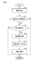
- FIG. 3 is a process chart showing a braking support method
- FIG. 4 is a diagram for explaining a wrap rate and an avoidance area
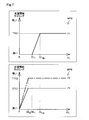
- FIG. 5 is a map showing the relationship between the lap rate and the braking assistance level in the first embodiment
- FIG. 6 is a map showing the relationship between the lap rate and the braking assistance level in the second embodiment
- FIG. 7 is a map showing the relationship between the lap rate and the braking assistance level in the third embodiment
- FIG. 1 is a view showing a vehicle provided with a braking assistance device according to the first embodiment
- FIG. 2 is a diagram showing a braking assistance device
- FIG. 3 is a process chart showing a braking support method
- FIG. 4 is a diagram for explaining a wrap rate and an avoidance area
- FIG. 5 is a map showing the relationship between the lap rate and the braking
- FIG. 8 is a diagram showing an example where the other object is an oncoming vehicle
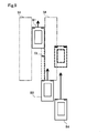
- FIG. 9 is a diagram showing an example in which another object is a vehicle approaching the vehicle from the rear side of the vehicle
- FIG. 10 is a view showing a vehicle having a braking assistance device according to the sixth embodiment.
- the braking assistance device 10 is mounted on a vehicle 500 and used.
- the braking assistance device 10 includes a control unit 100, a millimeter wave radar 21, a monocular camera 22, a vehicle speed sensor 24, a yaw rate sensor 25, a braking assistance actuator 30, and a braking device 502.
- the vehicle 500 includes wheels 501, a braking line 503, a steering wheel 504, a windshield 510, and a front bumper 520.
- the vehicle 500 may be provided with at least a millimeter wave radar 21 as a detection unit for detecting an object around the host vehicle, and the monocular camera 22 and the lidar (LIDAR: laser radar) together with the millimeter wave radar 21.
- LIDAR laser radar
- a stereo camera may be provided instead of the millimeter wave radar 21, and a stereo camera may be provided together with the millimeter wave radar 21.
- the millimeter wave radar 21 and the monocular camera 22 are provided as a detection unit.
- a braking device 502 is provided for each wheel 501.
- Each braking device 502 realizes the braking of each wheel 501 by the brake fluid pressure supplied via the braking line 503 according to the driver's brake pedal operation.
- the brake line 503 includes a brake piston and a brake fluid line that derives a brake fluid pressure according to the brake pedal operation.
- the brake assist actuator 30 is provided on the brake line 503, and hydraulic control can be performed independently of the operation of the brake pedal, whereby the brake assist is realized.
- a control signal line may be provided instead of the braking fluid line, and a configuration for operating the electric actuator provided in each braking device 502 may be employed.
- the braking support actuator 30 and the braking device 502 are collectively referred to as a "braking support unit".
- the steering wheel 504 is connected to the front wheel 501 via a steering rod and a steering mechanism.
- the control unit 100 includes one or more central processing units (CPUs) 110, a memory 120, and an input / output interface 140.
- the CPU 110, the memory 120, and the input / output interface 140 are bi-directionally connected via a bus.
- the memory 120 includes, for example, a ROM and a RAM.
- a millimeter wave radar 21, a monocular camera 22, a vehicle speed sensor 24, a yaw rate sensor 25, and a braking assistance actuator 30 are connected to the input / output interface 140 via control signal lines.
- the detection information of each sensor is input from the millimeter wave radar 21, the single-eye camera 22, the vehicle speed sensor 24, and the yaw rate sensor 25, and a control signal for instructing a braking assistance level is output to the braking assistance actuator 30.
- the braking assistance level is the degree of intervention of braking assistance by the braking device 502.
- the CPU 110 develops the program stored in the memory 120 and executes it to function as the attribute information acquisition unit 111, the collision determination unit 112, the avoidance area confirmation unit 113, and the support level determination unit 114, and performs braking support. .
- the processes of the attribute information acquisition unit 111, the collision determination unit 112, the avoidance area confirmation unit 113, and the support level determination unit 114 will be described in detail later.
- a device having the functions of the avoidance area confirmation unit 113 and the support level determination unit 114 is also simply referred to as a "control device".
- the millimeter wave radar 21 is a sensor for detecting a position and a distance of an object by emitting a millimeter wave and receiving a reflected wave reflected by the object, and includes a transmitter and a receiver.
- the millimeter wave radar 21 is disposed at the center of the front bumper 520, but the plurality of millimeter wave radars 21 may be disposed on the entire surface of the front bumper 520 or on both sides of the front bumper 520.
- the detection signal output from the millimeter wave radar 21 may be, for example, a signal consisting of a point sequence indicating the representative position of the object for which the reception wave has been processed in the processing circuit included in the millimeter wave radar 21, or It may be a signal indicating a received wave of processing.
- the CPU 110 performs signal processing for specifying the position and distance of an object.
- a rider may be used instead of the millimeter wave radar.
- the single-eye camera 22 is an imaging device including one imaging element such as a CCD, and is a sensor that receives visible light and outputs external shape information of an object as image data as a detection result.
- the image data output from the monocular camera 22 is composed of a plurality of frame images that are continuous in time series, and each frame image is represented by pixel data.
- the monocular camera 22 is disposed at the upper center of the windshield 510.
- the pixel data output from the monocular camera 22 is monochrome pixel data or color pixel data.
- the vehicle speed sensor 24 is a sensor that detects the rotational speed of the wheel 501, and is provided to each wheel 501.
- the detection signal output from the vehicle speed sensor 24 is a voltage value proportional to the wheel speed or a pulse wave indicating an interval according to the wheel speed.
- the yaw rate sensor 25 is a sensor that detects the rotational angular velocity of the vehicle 500.
- the yaw rate sensor 25 is disposed, for example, at the center of the vehicle 500.
- the detection signal output from the yaw rate sensor 25 is a voltage value proportional to the rotation direction and the angular velocity.
- the braking assistance actuator 30 is an actuator for realizing the braking by the braking device 502 regardless of the operation of the brake pedal by the driver.
- the braking assistance actuator 30 is provided on the braking line 503, and increases or decreases the hydraulic pressure in the braking line 503 in accordance with a control signal from the control unit 100.
- the braking assistance actuator 30 is configured of, for example, a module including an electric motor and a hydraulic piston driven by the electric motor.
- a braking control actuator that has already been introduced as an anti-slip device or anti-lock brake system may be used.
- a braking assistance method executed by the braking assistance device 10 according to the first embodiment will be described with reference to FIGS. 3 and 4.
- the braking assistance is repeatedly executed by the CPU 110 from when the start switch of the vehicle 500 is turned on to when it is turned off, or while the braking assistance switch provided in the vehicle 500 is set to on.
- the attribute information acquisition unit 111 acquires the attribute of the object around the host vehicle B0 (FIG. 4) using the detection results input from the detection unit such as the millimeter wave radar 21 and the single-eye camera 22 (FIG. 3, step S10).
- the detection result input from the millimeter wave radar 21 as the attribute, for example, the distance from the vehicle B0 to the object, the relative velocity of the object to the vehicle B0, the direction of the object, The degree of overlap between the host vehicle B0 and the target object, and the collision margin time TTC until the host vehicle B0 collides with the target object are calculated and acquired.
- the attribute information acquisition unit 111 calculates and acquires, for example, the relative position of the object with respect to the host vehicle B0 and the shape and size of the object using the image data from the single-eye camera 22.
- the degree of overlap is the degree of overlap of objects in the vehicle width direction of the host vehicle B0, and in the present embodiment, the overlap ratio OL between the host vehicle B0 and the object.
- the degree of overlap may be the amount of overlap with the object in the vehicle width direction of the host vehicle B0.
- the collision margin time TTC is a time until the object B0 collides with the object under the assumption that the relative velocity between the object B0 and the object is constant.
- the attribute information acquisition unit 111 executes the acquisition of the above attribute as needed while this routine is being executed.
- the collision determination unit 112 uses the attribute acquired by the attribute information acquisition unit 111 to determine whether an object exists in the traveling direction of the host vehicle B0 (FIG. 3, step S20). If no object exists in the traveling direction of the host vehicle B0 (FIG. 3, step S20, NO), the CPU 110 ends the present routine.
- the collision determination unit 112 uses the attribute acquired by the attribute information acquisition unit 111 to make the own vehicle B0 an own vehicle It is determined whether there is a possibility of collision with an object present in the traveling direction of B0 (FIG. 3, step S30).
- the collision determination unit 112 sets the host vehicle B0 and the target object B1 when the lap rate OL is greater than 0 and the collision margin time TTC is equal to or less than a first threshold corresponding to the relative speed stored in the memory 120. It is determined that there is a possibility of a collision with (FIG. 3, step S30, YES). If there is no collision possibility (FIG.
- the first threshold is a value capable of avoiding a collision with the target object B1 by braking the host vehicle B0 when the driver operates the brake pedal of the host vehicle B0 at the time when the collision margin time TTC is the first threshold.
- the vehicle 500 is provided with an alarm device that reports the possibility of a collision by sound, light, or vibration, and the CPU 110 sets, for example, a second threshold before the step S30, in which the collision margin time TTC is longer than the first threshold.
- a signal may be output via the input / output interface 140 at the specified timing, and notification by the alarm device may be performed. In the example shown in FIG.
- the object B1 is a preceding vehicle of the host vehicle B0, but the object B1 is not limited to a four-wheeled vehicle, and may be another moving object such as a two-wheeled vehicle or a person It may be a stationary object such as a three-dimensional structure.
- the avoidance area confirmation unit 113 confirms the avoidance area around the object B1 (FIG. 3, step S40).
- the avoidance area is an area where no other object around the target object B1 present in the traveling direction of the host vehicle B0 exists, and is an area for avoiding a collision with the target object B1 by steering the host vehicle B0. is there.
- the other object is an object different from the object B1.
- the other object B2 is a stationary object such as a broken vehicle or a guardrail.
- the avoidance area confirmation unit 113 multiplies the vehicle width of the host vehicle B0 by the lap rate OL, for example, to avoid the collision between the host vehicle B0 and the target object B1.
- the amount of lateral movement is calculated, and it is a region in which the host vehicle B0 travels assuming that the host vehicle B0 travels at the current vehicle speed and steering according to the lateral movement amount is performed in the host vehicle B0 Estimate the trajectory area.
- the avoidance area confirmation unit 113 uses the detection results from the millimeter wave radar 21 and the monocular camera 22 to confirm whether or not there is a pixel area indicating another object in the estimated traveling locus area.
- the avoidance area check unit 113 determines that there is no avoidance area when there is no pixel area indicating another object in the estimated traveling locus area, and avoids when there is a pixel area indicating another object. Determine that there is a region.
- An area S1 on the left side of the object B1 shown in FIG. 4 is a travel locus area to be estimated, and another object B2 exists in the area S1.
- An area S2 on the right side of the object B1 shown in FIG. 4 is an area in which the host vehicle B0 can not move by the collision margin time TTC. In the example shown in FIG. 4, the avoidance area check unit 113 determines that there is no avoidance area.
- the support level determination unit 114 determines the braking support level of the host vehicle B0 by the braking support unit according to the presence or absence of the avoidance area (FIG. 3, step S50). When there is no avoidance area, the support level determination unit 114 determines the braking support level to be higher than when there is an avoidance area.
- the braking assistance level defines the timing of the braking assistance start, and raising the braking assistance level means advancing the timing of the braking assistance start of the host vehicle B0 by the braking assistance unit.
- the memory 120 stores a map MP1 indicating the timing of the start of braking support when there is an avoidance area shown in FIG. 5 and a map MP2 indicating the timing of the start of braking support when there is no avoidance area. ing.
- the assistance level determination unit 114 refers to the map MP1 when there is an avoidance area, and refers to the map MP2 when there is no avoidance area, and determines the timing of the start of the braking assistance corresponding to the lap rate OL.
- the timing of the start of the braking assistance becomes later than when the lap rate OL is equal to or more than the threshold OL th
- the lap rate OL and the timing of the start of the braking support are defined so that the braking support is not performed.
- the lap rate OL when there is an avoidance area, when the lap rate OL is equal to or higher than the threshold OL th , braking assistance is started at the timing when the collision margin time becomes TTC 1 and the lap rate OL is the threshold OL th timing of the braking assistance start as smaller than the slower, smaller OL 1 the following than the overlap ratio OL threshold OL th, as brake assist is not performed, the overlap ratio OL braking assistance start timing relationship Is defined.
- the threshold value OL th is, for example, 40%
- the timing TTC1 of the start of the braking support at the threshold value OL th is, for example, a timing when the collision margin time TTC becomes 1.4 seconds.
- the value OL 1 is, for example, 30% and 25%.
- the relationship between the lap ratio OL and the timing of the start of the braking support is defined as described above, because, when the lap ratio OL is small, the collision avoidance by the operation of the steering wheel 504 is, for example, compared to the full lap. And it is easy. Also, for example, when the host vehicle B0 is trying to overtake the target object B1 while avoiding the target object B1, the host vehicle B0 may be consciously approaching the target object B1. In such a case, when the braking support is actively performed, the braking device 502 of the host vehicle B0 operates independently of the driver's intention when the host vehicle B0 tries to overtake the target object B1. There is a possibility that overtaking will not be achieved, and there is a possibility that the driver of the host vehicle B0 may feel discomfort, in order to reduce these possibilities.
- the braking assistance is started at the timing when the collision margin time becomes TTC1, and as the lap rate OL becomes smaller than the value OL 2.
- the relationship between the lap ratio OL and the timing of the start of the braking support is defined so that the braking support is not performed when the timing of the start of the braking support becomes late and the lap rate OL becomes zero.
- Value timing of braking assistance start in the map MP2 starts to become slow OL 2 is smaller than the value OL th the timing of the braking assistance start starts to slow down in the map MP1.
- the value OL 2 is, for example, a value such as 5%, 10%, or 15%.
- the assistance level determination unit 114 outputs a signal to the braking assistance actuator 30 so that the braking assistance is performed at the determined timing of the braking assistance start, and causes the braking device 502 to execute the braking assistance (FIG. 3, Step S60).
- the overlap degree OL is predetermined.
- the timing of the start of the braking support in the case of being smaller than the value OL th is earlier than the timing of the start of the braking support in the presence of the avoidance area, and therefore objects existing in the traveling direction of the host vehicle B0 and the host vehicle B0
- the possibility of collision with the object B1 can be reduced.
- another object B2 is present around the object B1, the possibility of collision between the host vehicle B0 and the other object B2 can be reduced.
- the braking assistance is performed when there is no avoidance area, so the vehicle B0 and the vehicle B0 exist in the traveling direction
- the possibility of collision with the object B1 can be reduced.
- the possibility of collision between the host vehicle B0 and the other object B2 can be reduced.
- the braking support level defines the strength of the braking support.
- raising the braking assistance level means increasing the strength of the braking assistance of the host vehicle B0 by the braking assistance unit.
- the memory 120 stores a map MP3 indicating the magnitude of the braking force in the presence of the avoidance area shown in FIG. 6 and a map MP4 indicating the magnitude of the braking force in the absence of the avoidance area. ing.
- the support level determination unit 114 refers to the map MP3 when there is an avoidance area, and determines the magnitude of the braking force with reference to the map MP4 when there is no avoidance area.
- the maps MP3 and MP4 show the relationship between the lap rate OL and the magnitude of the braking force when the collision margin time TTC is the first threshold, but the maps MP3 and MP4 have the collision margin time TTC. The relationship in the case of being the said 2nd threshold may be shown.
- the relationship between the lap ratio and the braking force is defined so that the braking support is not performed.
- the map MP3 when the lap rate OL is equal to or higher than the threshold OL th , braking assistance is performed with the magnitude of the braking force F1. As the lap rate OL becomes smaller than the threshold OL th , the braking force decreases.
- the magnitude F1 of the braking force when the lap rate OL is equal to or greater than the threshold OL th is, for example, 3G.
- 1 G is an acceleration of the same magnitude as the gravitational acceleration.
- the relationship between the lap rate OL and the magnitude of the braking force is defined as described above, in the same manner as the timing of the start of the braking support is defined according to the lap rate OL in the first embodiment.
- the braking device 502 of the vehicle B0 operates independently of the driver's intention to reduce the possibility that overtaking will not be achieved and the possibility that the driver of the host vehicle B0 will feel uncomfortable.
- braking assistance is performed with the magnitude of the braking force F1 when the lap rate OL is the value OL 2 or more, and the braking force becomes smaller as the lap rate OL becomes smaller than the value OL 2.
- the relationship between the lap ratio OL and the braking force is defined so that braking assistance is not performed when the lap ratio OL becomes smaller and becomes zero.
- Map values OL 2 the braking force starts to become small in the MP4 is less than the threshold OL th braking force starts to become smaller in the map MP3.
- the second embodiment there is a possibility of collision between the host vehicle B0 and the target object B1 existing in the traveling direction of the host vehicle B0, there is no avoidance area around the target object B1, and the overlap degree OL is predetermined.
- the braking force in the case of being smaller than the threshold OL th is larger than the braking force in the presence of the avoidance area, so the possibility of collision between the host vehicle B0 and the target object B1 present in the traveling direction of the host vehicle B0 is reduced. can do.
- another object B2 is present around the object B1, the possibility of collision between the host vehicle B0 and the other object B2 can be reduced.
- the braking assistance is performed when there is no avoidance area, so the vehicle B0 and the vehicle B0 are in the traveling direction
- the possibility of collision with the object B1 can be reduced.
- the possibility of collision between the host vehicle B0 and the other object B2 can be reduced.
- the braking assistance level defines the timing of braking assistance start and the magnitude of the braking force.
- raising the braking assistance level means advancing the timing of starting the braking assistance of the host vehicle B0 by the braking assistance unit and increasing the braking force.
- the memory 120 shows a map MP5 indicating the timing of the start of braking support when there is an avoidance area shown in FIG. 7 and the timing of the start of braking support when there is no avoidance area and the magnitude of the braking force
- the map MP6 is stored.
- the support level determination unit 114 refers to the map MP5 when there is an avoidance area, and determines the magnitude of the braking force with reference to the map MP6 when there is no avoidance area.
- the relationship of the timing of the start of the braking support is set.
- the first braking force F1 at the timing TTC1 of the start of the braking support is, for example, 3G.
- the relationship between the timing at which the braking assistance is started by the first braking force F1 and the lap rate OL is the same as the relationship described using the map MP2 described in the first embodiment. is there.
- braking assistance is performed with the second braking force F2 smaller than the first braking force F1 at a timing earlier than the timing when braking assistance is started with the first braking force F1. Is done.
- the third embodiment when there is a collision possibility between the host vehicle B0 and the target object B1 existing in the traveling direction of the host vehicle B0 and there is no avoidance area around the target object B1, first, it is relatively small. After the braking assistance is performed with the second braking force F2, the braking assistance is performed with the first braking force F1 larger than the second braking force F2, so that the braking assistance can be performed in multiple stages, and the vehicle B0 and The possibility of collision with the object B1 can be further reduced. Further, when another object B2 is present around the object B1, the possibility of collision between the host vehicle B0 and the other object B2 can be further reduced.
- the braking assistance is performed when there is no avoidance area, so as in the first and second embodiments, It is possible to reduce the possibility of collision between the host vehicle B0 and the target object B1 present in the traveling direction of the host vehicle B0.
- the possibility of collision between the host vehicle B0 and the other object B2 can be reduced.
- the avoidance area confirmation unit 113 is an area around the object B1 in which the other object is the moving object and the vehicle 500 is steered in the traveling direction of the vehicle 500. When it is predicted that another object is located in the moved area, it may be determined that there is no avoidance area.
- the other object is the oncoming vehicle B3 traveling opposite to the traveling direction of the host vehicle B0.
- the attribute information acquisition unit 111 uses image data from the millimeter wave radar 21 and the single-eye camera 22 to determine the distance to the oncoming vehicle B3, the relative speed of the oncoming vehicle B3 to the own vehicle B0, the direction of the oncoming vehicle B3, and the own vehicle B0.
- the lap rate OL etc. of the oncoming vehicle B3 and the like are calculated and acquired.
- the avoidance area confirmation unit 113 determines whether the oncoming vehicle B3 exists in the traveling locus area by the collision allowance time TTC with the target object B1. In the example illustrated in FIG. 8, the oncoming vehicle B3 is present in the area S4 by the collision allowance time TTC with the object B1.
- An area S3 on the left side of the target object B1 is an area in which the host vehicle B0 can not move by the collision allowance time TTC with the target object B1.
- the avoidance area check unit 113 determines that there is no avoidance area.
- the braking assistance level is equal to the avoidance area. Since it is determined that the braking assistance level is higher than in a certain case, the collision possibility between the host vehicle B0, the object B1 and the host vehicle B0 and other objects can be reduced. Further, the collision possibility between the host vehicle B0, the target object B1, the host vehicle B0, and the oncoming vehicle B3 as another target object can be reduced.
- the detection unit is the millimeter wave radar 21 and the monocular camera 22 provided in front of the vehicle 500.
- the vehicle 500 further includes the millimeter wave radar behind the vehicle 500, A monocular camera may be provided as a detection unit, and the CPU 110 may detect a vehicle approaching the host vehicle B0 from the rear side of the host vehicle B0 from the detection results of the millimeter wave radar and the monocular camera at the rear.
- the avoidance area confirmation unit 113 is a case where the other object is the vehicle B4 approaching the own vehicle B0 from the rear side of the own vehicle B0 as shown in FIG.
- the attribute information acquisition unit 111 uses image data from a millimeter wave radar and a single-eye camera provided behind the vehicle 500 to determine the distance to the vehicle B4, the relative speed of the vehicle B4 with respect to the host vehicle B0, and the direction of the vehicle B4.
- the lap rate OL between the host vehicle B0 and the vehicle B4 is calculated and acquired. In the example shown in FIG.
- the vehicle B4 exists in the area S6 by the collision allowance time TTC with the object B1.
- An area S5 on the left side of the object B1 is an area in which the host vehicle B0 can not move by the collision allowance time TTC with the object B1.
- the avoidance area check unit 113 determines that there is no avoidance area.
- the possibility of collision between the host vehicle B0 and the target object B1 and the vehicle B4 approaching the host vehicle B0 from the rear side can be reduced.
- the steering wheel 504 is connected to the front wheel 501 via a steering device 42 including a steering rod and a steering mechanism.
- a steering assist device 31 capable of driving the steering device 42 by an actuator, for example, an electric motor, is disposed in the steering device 42.
- the steering assist device 31 can control the drive of the steering device 42 independently of the operation of the steering wheel 504, and the steering assist is realized by the control of the control unit 100a.
- the control unit 100a may output a control signal to the steering device 42 to cause the steering device to perform steering assistance to the avoidance area. With such a form, the collision possibility between the host vehicle B0 and the target object B1 can be reduced.
- the support level determination unit 114 determines the timing of the start of the braking support or the magnitude of the braking force with reference to the map stored in the memory, but instead, in the memory
- the expression representing the relationship between the timing of braking assistance start or the magnitude of the braking force and the lap rate OL is stored, and the assistance level determination unit 114 determines the timing of braking assistance start or the magnitude of braking force according to the lap rate OL. You may decide
- the present disclosure can also be implemented in various forms other than the braking assistance device.
- the present invention can be realized in the form of a braking assistance method, a computer program for realizing such a method, a storage medium storing such a computer program, a vehicle equipped with a collision estimation device, and the like.
- some or all of the functions and processes implemented by software may be implemented by hardware.
- some or all of the functions and processes implemented by hardware may be implemented by software.
- various circuits such as integrated circuits, discrete circuits, or circuit modules combining those circuits may be used.
- the present disclosure is not limited to the above-described embodiments, and can be implemented with various configurations without departing from the scope of the present disclosure.
- the technical features in the embodiments corresponding to the technical features in the modes described in the section of the summary of the invention can be used to solve some or all of the problems described above, or the effects of the effects described above. Replacements and combinations can be made as appropriate to achieve part or all. Also, if the technical features are not described as essential in the present specification, they can be deleted as appropriate.
Landscapes
- Engineering & Computer Science (AREA)
- Transportation (AREA)
- Mechanical Engineering (AREA)
- Automation & Control Theory (AREA)
- Human Computer Interaction (AREA)
- Regulating Braking Force (AREA)
- Traffic Control Systems (AREA)
Abstract
自車両(B0)と自車両の進行方向に存在する対象物(B1)との衝突可能性がある場合に、対象物の周囲に他の対象物(B2~B4)が存在しない領域であって操舵によって衝突を回避するための回避領域を確認し、回避領域がない場合に、回避領域がある場合よりも、自車両の制動を支援する制動支援部(30、502)による自車両の制動支援レベルを高くし、制動支援を実行する。制動支援レベルを高くすることには、制動支援部による自車両の制動支援開始のタイミングを早くすることと、制動支援部による自車両の制動支援の強さを大きくすることと、の少なくとも一方が含まれる。
Description
本出願は、2017年11月24日に出願された日本出願番号2017-225511号に基づくもので、ここにその記載内容を援用する。
本開示は、車両の制動支援装置、制御装置及び制動支援方法に関する。
カメラやレーダからの検出結果を用いて、車両の周囲に存在する障害物との衝突を回避するための技術が知られている。特許文献1には、自車両が前方障害物に衝突する可能性がある場合において、自車両と前方障害物とのオーバーラップ率が自車両の車速に応じた所定値以上である場合には自車両を制動させる制御を行い、オーバーラップ率が自車両の車速に応じた所定値未満である場合には自車両を制動させる制御を行わないことが記載されている。
特許文献1記載の技術では、オーバーラップ率に応じて車両を制動させるか否かを判定しているため、例えば、前方障害物の周囲にガードレール等の他の障害物があり、操舵回避にて回避が難しい状況下においては、オーバーラップ率が低いと、自車両を制動させる制御が行われないおそれがある。
本開示は、上述の課題を解決するためになされたものであり、以下の形態として実現することが可能である。
本開示の一形態によれば、車両の制動支援装置が提供される。この制動支援装置は、自車両の周囲の対象物を検出するための検出部と;前記自車両の制動を支援する制動支援部と;前記制動支援部を制御する制御部と、を備え;前記制御部は;前記検出部の検出結果を用いて、前記自車両が前記自車両の進行方向に存在する対象物に衝突する可能性があると判断した場合に、前記自車両の進行方向に存在する対象物の周囲の他の対象物が存在しない領域であって前記自車両の操舵によって前記衝突を回避するための回避領域を確認し;前記回避領域がない場合、前記回避領域がある場合よりも前記制動支援部による前記自車両の制動支援レベルを高くして、前記制動支援部に制動支援を実行させ;前記制動支援レベルを高くすることは、前記自車両に対する制動支援開始のタイミングを早くすることと、前記自車両に対する制動支援の強さを大きくすることと、の少なくとも一方を含む。
この形態によれば、自車両と自車両の進行方向に存在する対象物との衝突可能性があり、対象物の周囲に回避領域がない場合には、回避領域がある場合に比べて制動支援が早く開始されることと、制動支援の強さが大きくされることと、の少なくとも一方が行われるので、自車両と自車両の進行方向に存在する対象物との衝突可能性を低減することができる。また、対象物の周囲の他の対象物との衝突可能性を低減することができる。
本開示についての上記目的およびその他の目的、特徴や利点は、添付の図面を参照しながら下記の詳細な記述により、より明確になる。その図面は、
図1は、第1実施形態に係る制動支援装置を備える車両を示す図であり、
図2は、制動支援装置を示す図であり、
図3は、制動支援方法を示す工程図であり、
図4は、ラップ率及び回避領域を説明するための図であり、
図5は、第1実施形態におけるラップ率と制動支援レベルの関係を示すマップであり、
図6は、第2実施形態におけるラップ率と制動支援レベルの関係を示すマップであり、
図7は、第3実施形態におけるラップ率と制動支援レベルの関係を示すマップであり、
図8は、他の対象物が対向車両である例を示す図であり、
図9は、他の対象物が自車両の後側方から自車両に接近する車両である例を示す図であり、
図10は、第6実施形態に係る制動支援装置を有する車両を示す図である。
・第1実施形態
図1に示すように、第1実施形態に係る制動支援装置10は、車両500に搭載されて用いられる。制動支援装置10は、制御部100と、ミリ波レーダ21と、単眼カメラ22と、車速センサ24と、ヨーレートセンサ25と、制動支援アクチュエータ30と、制動装置502と、を備える。車両500は、車輪501と、制動ライン503と、ステアリングホイール504と、フロントガラス510と、フロントバンパ520と、を備える。車両500には、自車両の周囲の対象物を検出する検出部として、少なくとも、ミリ波レーダ21を備えられていれば良く、ミリ波レーダ21と共に、単眼カメラ22とライダー(LIDAR:レーザレーダ)との少なくともいずれか1つが備えられていてもよい。または、ミリ波レーダ21に代えてステレオカメラが備えられていてもよく、ミリ波レーダ21と共にステレオカメラが備えられていても良い。本実施形態においては、ミリ波レーダ21及び単眼カメラ22が検出部として備えられている。
図1に示すように、第1実施形態に係る制動支援装置10は、車両500に搭載されて用いられる。制動支援装置10は、制御部100と、ミリ波レーダ21と、単眼カメラ22と、車速センサ24と、ヨーレートセンサ25と、制動支援アクチュエータ30と、制動装置502と、を備える。車両500は、車輪501と、制動ライン503と、ステアリングホイール504と、フロントガラス510と、フロントバンパ520と、を備える。車両500には、自車両の周囲の対象物を検出する検出部として、少なくとも、ミリ波レーダ21を備えられていれば良く、ミリ波レーダ21と共に、単眼カメラ22とライダー(LIDAR:レーザレーダ)との少なくともいずれか1つが備えられていてもよい。または、ミリ波レーダ21に代えてステレオカメラが備えられていてもよく、ミリ波レーダ21と共にステレオカメラが備えられていても良い。本実施形態においては、ミリ波レーダ21及び単眼カメラ22が検出部として備えられている。
制動装置502は、各車輪501に備えられている。各制動装置502は、運転者の制動ペダル操作に応じて制動ライン503を介して供給されるブレーキ液圧によって、各車輪501の制動を実現する。制動ライン503には制動ペダル操作に応じたブレーキ液圧を派生させるブレーキピストンおよびブレーキ液ラインが含まれる。本実施形態においては、制動支援アクチュエータ30が制動ライン503に備えられ、制動ペダル操作とは独立して液圧制御が可能であり、これにより制動支援が実現される。なお、制動ライン503としては、ブレーキ液ラインに代えて制御信号線を備え、各制動装置502に備えられている電動アクチュエータを作動させる構成が採用されても良い。制動支援アクチュエータ30と制動装置502とを合わせて「制動支援部」とも呼ぶ。
ステアリングホイール504は、ステアリングロッドおよび操舵機構を介して前側の車輪501と接続されている。
図2に示すように、制御部100は、1以上の中央処理装置(CPU)110と、メモリ120と、入出力インタフェース140とを備えている。CPU110、メモリ120および入出力インタフェース140は、バスを介して双方向通信可能に接続されている。メモリ120は、例えばROMと、RAMと、を含んでいる。入出力インタフェース140には、ミリ波レーダ21、単眼カメラ22、車速センサ24、ヨーレートセンサ25、制動支援アクチュエータ30がそれぞれ制御信号線を介して接続されている。ミリ波レーダ21、単眼カメラ22、車速センサ24、ヨーレートセンサ25からは、各センサの検出情報が入力され、制動支援アクチュエータ30に対しては制動支援レベルを指示する制御信号が出力される。制動支援レベルとは、制動装置502による制動支援の介入の度合いである。CPU110は、メモリ120に格納されているプログラムを展開して実行することで、属性情報取得部111、衝突判定部112、回避領域確認部113、支援レベル決定部114として機能し、制動支援を行う。属性情報取得部111、衝突判定部112、回避領域確認部113、支援レベル決定部114の処理については詳細を後述する。制御部100のうち、回避領域確認部113,支援レベル決定部114の機能を備える装置を、単に、「制御装置」とも呼ぶ。
ミリ波レーダ21はミリ波を射出し、対象物によって反射された反射波を受信することによって対象物の位置および距離を検出するためのセンサであり、送信器と受信器とを備えている。本実施形態において、ミリ波レーダ21は、フロントバンパ520の中央に配置されているが、フロントバンパ520の全面に複数、または、フロントバンパ520の両側面に配置されていても良い。ミリ波レーダ21から出力される検出信号は、例えば、ミリ波レーダ21が備える処理回路において受信波が処理された対象物の代表位置を示す点列からなる信号であっても良く、あるいは、未処理の受信波を示す信号であっても良い。未処理の受信波が検出信号として用いられる場合には、CPU110は、対象物の位置および距離を特定するための信号処理を実行する。なお、ミリ波レーダに代えて、ライダーが用いられても良い。
単眼カメラ22は、CCD等の撮像素子を1つ備える撮像装置であり、可視光を受光することによって対象物の外形情報を検出結果である画像データとして出力するセンサである。単眼カメラ22から出力される画像データは、時系列的に連続する複数のフレーム画像によって構成されており、各フレーム画像は画素データにより表されている。本実施形態において、単眼カメラ22はフロントガラス510の上部中央に配置されている。単眼カメラ22から出力される画素データは、モノクロの画素データまたはカラーの画素データである。
車速センサ24は、車輪501の回転速度を検出するセンサであり、各車輪501に備えられている。車速センサ24から出力される検出信号は、車輪速度に比例する電圧値または車輪速度に応じた間隔を示すパルス波である。車速センサ24からの検出信号を用いることによって、車両速度、車両の走行距離等の情報を得ることができる。
ヨーレートセンサ25は、車両500の回転角速度を検出するセンサである。ヨーレートセンサ25は、例えば、車両500の中央部に配置されている。ヨーレートセンサ25から出力される検出信号は、回転方向と角速度に比例する電圧値である。
制動支援アクチュエータ30は、運転者による制動ペダル操作とは無関係に制動装置502による制動を実現するためのアクチュエータである。本実施形態において、制動支援アクチュエータ30は、制動ライン503に備えられており、制御部100からの制御信号に従って制動ライン503における油圧を増減させる。制動支援アクチュエータ30は、例えば、電動モータと電動モータにより駆動される油圧ピストンとを備えるモジュールから構成されている。あるいは、横滑り防止装置、アンチロックブレーキシステムとして既に導入されている制動制御アクチュエータが用いられても良い。
図3及び図4を参照して第1実施形態に係る制動支援装置10によって実行される、制動支援方法について説明する。この制動支援は、車両500のスタートスイッチがオンされてからオフされるまでの間、または、車両500に備えられた制動支援スイッチがオンに設定されている間、CPU110によって繰り返し実行される。
属性情報取得部111は、ミリ波レーダ21、単眼カメラ22といった検出部から入力される検出結果を用いて、自車両B0(図4)の周囲における対象物の属性を取得する(図3、ステップS10)。本実施形態において、属性としては、ミリ波レーダ21から入力される検出結果を用いて、例えば、自車両B0から対象物までの距離、自車両B0に対する対象物の相対速度、対象物の向き、自車両B0と対象物との重なり度合い、自車両B0が対象物と衝突するまでの衝突余裕時間TTCを算出、取得する。また、属性情報取得部111は、単眼カメラ22からの画像データを用いて、例えば、自車両B0に対する対象物の相対位置、対象物の形状や大きさを算出、取得する。なお、重なり度合いとは、自車両B0の車幅方向における対象物の重なりの度合いであり、本実施形態では、自車両B0と対象物とのラップ率OLである。重なり度合いは、自車両B0の車幅方向における対象物との重なりの量であってもよい。衝突余裕時間TTCとは、自車両B0と対象物との相対速度が一定であると仮定した際の自車両B0と対象物が衝突するまでの時間である。属性情報取得部111は、本ルーチンが実行されている間、上記の属性の取得を随時実行する。
次に、衝突判定部112は、属性情報取得部111が取得した属性を用いて、自車両B0の進行方向に対象物が存在するか否かを判定する(図3、ステップS20)。自車両B0の進行方向に対象物が存在しない場合には(図3、ステップS20、NO)、CPU110は、本ルーチンを終了する。
自車両B0の進行方向に対象物が存在する場合には(図3、ステップS20、YES)、衝突判定部112は、属性情報取得部111が取得した属性を用いて、自車両B0が自車両B0の進行方向に存在する対象物と衝突する可能性があるか否かを判定する(図3、ステップS30)。ステップS30では、衝突判定部112は、ラップ率OLが0より大きく、衝突余裕時間TTCがメモリ120に記憶された相対速度に応じた第1閾値以下である場合に、自車両B0と対象物B1との衝突可能性があると判定する(図3、ステップS30、YES)。衝突可能性がない場合には(図3、ステップS30、NO)、CPU110は本ルーチンを終了する。第1閾値は、衝突余裕時間TTCが第1閾値の時点においてドライバにより自車両B0の制動ペダルが操作された場合に、自車両B0の制動によって対象物B1との衝突を回避可能な値である。車両500は、音や光、振動により衝突の可能性を報知する警報装置を備え、CPU110は、ステップS30の前に、例えば、衝突余裕時間TTCが上記第1閾値よりも長い第2閾値となったタイミングで入出力インタフェース140を介して信号を出力し、警報装置による報知を行ってもよい。なお、図4に示す例では、対象物B1は、自車両B0の先行車両であるが、対象物B1は、四輪車に限らず、二輪車、人物等の他の移動物であってもよいし、立体構造物等の静止物であってもよい。
回避領域確認部113は、衝突判定部112により衝突可能性があると判定された場合に、対象物B1の周囲の回避領域を確認する(図3、ステップS40)。回避領域は、自車両B0の進行方向に存在する対象物B1の周囲の他の対象物が存在しない領域であって、自車両B0の操舵によって対象物B1との衝突を回避するための領域である。他の対象物とは、対象物B1とは異なる対象物である。本実施形態では、他の対象物B2は、故障車両、ガードレール等の静止物である。本実施形態では、回避領域確認部113は、例えば、自車両B0の車幅にラップ率OLを乗じることで、自車両B0と対象物B1との衝突を回避するために必要な自車両B0の横移動量を算出し、自車両B0が現在の車両速度で走行し、かつ、自車両B0において横移動量に応じた操舵が行われたと仮定した場合の自車両B0が走行する領域である走行軌跡領域を推定する。回避領域確認部113は、ミリ波レーダ21、単眼カメラ22からの検出結果を用いて、推定される走行軌跡領域に、他の対象物を示す画素領域が存在するか否かを確認する。回避領域確認部113は、推定される走行軌跡領域に、他の対象物を示す画素領域がない場合には回避領域がないと判定し、他の対象物を示す画素領域がある場合には回避領域があると判定する。図4に示す対象物B1の左側の領域S1は、推定される走行軌跡領域であり、領域S1には他の対象物B2が存在する。図4に示す対象物B1の右側の領域S2は、衝突余裕時間TTCまでに自車両B0が移動することができない領域である。図4に示す例では、回避領域確認部113は回避領域がないと判定する。
回避領域の確認後、支援レベル決定部114は回避領域の有無に応じて、制動支援部による自車両B0の制動支援レベルを決定する(図3、ステップS50)。支援レベル決定部114は、回避領域がない場合には、回避領域がある場合よりも制動支援レベルを高く決定する。本実施形態では、制動支援レベルは、制動支援開始のタイミングを規定しており、制動支援レベルを高くすることは、制動支援部による自車両B0の制動支援開始のタイミングを早くすることである。
本実施形態では、メモリ120には、図5に示す回避領域がある場合の制動支援開始のタイミングを示すマップMP1と、回避領域がない場合の制動支援開始のタイミングを示すマップMP2とが記憶されている。支援レベル決定部114は、回避領域がある場合にはマップMP1を参照し、回避領域がない場合にはマップMP2を参照して、ラップ率OLに対応する制動支援開始のタイミングを決定する。マップMP1では、ラップ率OLが予め定められた値(以下、閾値OLth)よりも小さい場合に、ラップ率OLが閾値OLth以上の場合よりも制動支援開始のタイミングが遅くなるように、又は制動支援が行われないように、ラップ率OLと制動支援開始のタイミングとが規定されている。具体的には、回避領域がある場合のマップMP1では、ラップ率OLが閾値OLth以上の場合には衝突余裕時間がTTC1となったタイミングで制動支援が開始され、ラップ率OLが閾値OLthよりも小さくなるにつれて制動支援開始のタイミングが遅くなり、ラップ率OLが閾値OLthよりも小さい値OL1以下では、制動支援が行われないように、ラップ率OLと制動支援開始のタイミングの関係が規定されている。閾値OLthは、例えば40%であり、閾値OLthにおける制動支援開始のタイミングTTC1は、例えば衝突余裕時間TTCが1.4秒となったタイミングである。値OL1は、例えば、30%、25%である。なお、ラップ率OLと制動支援開始のタイミングとの関係が上記のように規定されているのは、ラップ率OLが小さい場合には、ステアリングホイール504の操作による衝突の回避が、例えばフルラップに比べると容易であるためである。また、例えば、自車両B0が対象物B1を避けて追い抜こうとしている場合等、自車両B0が意識的に対象物B1に接近していることがある。このような場合に制動支援が積極的に行われると、自車両B0が対象物B1を追い抜こうとする際に自車両B0の制動装置502がドライバの意思とは無関係に作動することによって、追い抜きが達成されない可能性や、自車両B0のドライバが違和感を覚える可能性があり、これらの可能性を低減するためである。
回避領域がない場合のマップMP2では、ラップ率OLが値OL2以上の場合には衝突余裕時間がTTC1となったタイミングで制動支援が開始され、ラップ率OLが値OL2よりも小さくなるにつれて制動支援開始のタイミングが遅くなり、ラップ率OLが0になると制動支援が行われないように、ラップ率OLと制動支援開始のタイミングの関係が規定されている。マップMP2における制動支援開始のタイミングが遅くなり始める値OL2は、マップMP1における制動支援開始のタイミングが遅くなり始める値OLthよりも小さい。値OL2は、例えば、5%、10%、15%といった値である。
次に、支援レベル決定部114は、決定した制動支援開始のタイミングで制動支援が実行されるように制動支援アクチュエータ30に信号を出力して、制動装置502に制動支援を実行させる(図3、ステップS60)。
第1実施形態によれば、自車両B0と自車両B0の進行方向に存在する対象物B1との衝突可能性があり、対象物B1の周囲に回避領域がなく、重なり度合いOLが予め定められた値OLthよりも小さい場合における制動支援の開始のタイミングは、回避領域がある場合における制動支援の開始のタイミングに比べて早くなるので、自車両B0と自車両B0の進行方向に存在する対象物B1との衝突可能性を低減することができる。また、対象物B1の周囲に他の対象物B2が存在する場合、自車両B0と他の対象物B2との衝突可能性を低減することができる。
また、第1実施形態によれば、ラップ率OLが比較的小さい場合であっても、回避領域がない場合には制動支援が行われるので、自車両B0と自車両B0の進行方向に存在する対象物B1との衝突可能性を低減することができる。また、対象物B1の周囲に他の対象物B2が存在する場合、自車両B0と他の対象物B2との衝突可能性を低減することができる。
・第2実施形態
図6を参照しつつ、第2実施形態に係る制動支援装置10について、第1実施形態と異なる点を主に説明する。第2実施形態では、制動支援レベルは制動支援の強さを規定している。第2実施形態において、制動支援レベルを高くすることは、制動支援部による自車両B0の制動支援の強さを大きくすることである。言い換えると、制動支援部が発生させる制動力を大きくすることである。本実施形態では、メモリ120には、図6に示す回避領域がある場合の制動力の大きさを示すマップMP3と、回避領域がない場合の制動力の大きさを示すマップMP4とが記憶されている。支援レベル決定部114は、回避領域がある場合にはマップMP3を参照し、回避領域がない場合にはマップMP4を参照して制動力の大きさを決定する。本実施形態において、マップMP3、MP4は、衝突余裕時間TTCが上記第1閾値である場合のラップ率OLと制動力の大きさとの関係を示すが、マップMP3、MP4は、衝突余裕時間TTCが上記第2閾値である場合の関係を示していてもよい。
図6を参照しつつ、第2実施形態に係る制動支援装置10について、第1実施形態と異なる点を主に説明する。第2実施形態では、制動支援レベルは制動支援の強さを規定している。第2実施形態において、制動支援レベルを高くすることは、制動支援部による自車両B0の制動支援の強さを大きくすることである。言い換えると、制動支援部が発生させる制動力を大きくすることである。本実施形態では、メモリ120には、図6に示す回避領域がある場合の制動力の大きさを示すマップMP3と、回避領域がない場合の制動力の大きさを示すマップMP4とが記憶されている。支援レベル決定部114は、回避領域がある場合にはマップMP3を参照し、回避領域がない場合にはマップMP4を参照して制動力の大きさを決定する。本実施形態において、マップMP3、MP4は、衝突余裕時間TTCが上記第1閾値である場合のラップ率OLと制動力の大きさとの関係を示すが、マップMP3、MP4は、衝突余裕時間TTCが上記第2閾値である場合の関係を示していてもよい。
図6に示すように、回避領域がある場合のマップMP3では、ラップ率OLが閾値OLthよりも小さい場合に、ラップ率が閾値OLth以上の場合よりも制動力が小さくなるように、又は制動支援が行われないように、ラップ率と制動力の関係が規定されている。具体的には、マップMP3では、ラップ率OLが閾値OLth以上の場合には制動力F1の大きさで制動支援が行われ、ラップ率OLが閾値OLthよりも小さくなるにつれて制動力が小さくなり、ラップ率OLが閾値OLthよりも小さい値OL1以下では、制動力がゼロとなるように、ラップ率と制動力の大きさの関係が規定されている。ラップ率OLが閾値OLth以上である場合の制動力の大きさF1は、例えば、3Gである。なお、1Gは、重力加速度と同じ大きさの加速度である。ラップ率OLと制動力の大きさの関係が上記のように規定されているのは、第1実施形態においてラップ率OLに応じて制動支援開始のタイミングが規定されていることと同様に、自車両B0の制動装置502がドライバの意思とは無関係に作動することによって、追い抜きが達成されない可能性や、自車両B0のドライバが違和感を覚える可能性を低減するためである。
回避領域がない場合のマップMP4では、ラップ率OLが値OL2以上の場合には制動力F1の大きさで制動支援が行われ、ラップ率OLが値OL2よりも小さくなるにつれて制動力が小さくなり、ラップ率OLが0になると制動支援が行われないように、ラップ率OLと制動力の関係が規定されている。マップMP4において制動力が小さくなり始める値OL2は、マップMP3において制動力が小さくなり始める閾値OLthよりも小さい。
第2実施形態によれば、自車両B0と自車両B0の進行方向に存在する対象物B1との衝突可能性があり、対象物B1の周囲に回避領域がなく、重なり度合いOLが予め定められた閾値OLthよりも小さい場合の制動力は、回避領域がある場合の制動力よりも大きくなるので、自車両B0と自車両B0の進行方向に存在する対象物B1との衝突可能性を低減することができる。また、対象物B1の周囲に他の対象物B2が存在する場合、自車両B0と他の対象物B2との衝突可能性を低減することができる。
また、第1実施形態と同様に、ラップ率OLが比較的小さい場合であっても、回避領域がない場合には制動支援が行われるので、自車両B0と自車両B0の進行方向に存在する対象物B1との衝突可能性を低減することができる。また、対象物B1の周囲に他の対象物B2が存在する場合、自車両B0と他の対象物B2との衝突可能性を低減することができる。
・第3実施形態
図7を参照しつつ、第3実施形態に係る制動支援装置10について、第1実施形態及び第2実施形態と異なる点を主に説明する。第3実施形態では、制動支援レベルは制動支援開始のタイミング及び制動力の大きさを規定している。第3実施形態において制動支援レベルを高くすることは、制動支援部による自車両B0の制動支援開始のタイミングを早くすること及び制動力を大きくすることである。本実施形態では、メモリ120には、図7に示す回避領域がある場合の制動支援開始のタイミングを示すマップMP5と、回避領域がない場合の制動支援開始のタイミング及び制動力の大きさを示すマップMP6とが記憶されている。支援レベル決定部114は、回避領域がある場合にはマップMP5を参照し、回避領域がない場合にはマップMP6を参照して制動力の大きさを決定する。
図7を参照しつつ、第3実施形態に係る制動支援装置10について、第1実施形態及び第2実施形態と異なる点を主に説明する。第3実施形態では、制動支援レベルは制動支援開始のタイミング及び制動力の大きさを規定している。第3実施形態において制動支援レベルを高くすることは、制動支援部による自車両B0の制動支援開始のタイミングを早くすること及び制動力を大きくすることである。本実施形態では、メモリ120には、図7に示す回避領域がある場合の制動支援開始のタイミングを示すマップMP5と、回避領域がない場合の制動支援開始のタイミング及び制動力の大きさを示すマップMP6とが記憶されている。支援レベル決定部114は、回避領域がある場合にはマップMP5を参照し、回避領域がない場合にはマップMP6を参照して制動力の大きさを決定する。
回避領域がある場合のマップMP5では、ラップ率OLが閾値OLthよりも小さい場合に、ラップ率OLが閾値OLth以上の場合よりも制動支援開始のタイミングが遅くなるように、ラップ率OLと制動支援開始のタイミングの関係が設定されている。制動支援開始のタイミングTTC1における第1制動力F1は、例えば3Gである。
回避領域がない場合のマップMP6において、第1制動力F1で制動支援が開始されるタイミングとラップ率OLとの関係は、第1実施形態で説明したマップMP2を用いて説明した関係と同様である。本実施形態では、回避領域がない場合には、さらに、第1制動力F1で制動支援が開始されるタイミングよりも早いタイミングにおいて、第1制動力F1よりも小さな第2制動力F2で制動支援が行われる。
第3実施形態によれば、自車両B0と自車両B0の進行方向に存在する対象物B1との衝突可能性があり、対象物B1の周囲に回避領域がない場合に、まず、比較的小さな第2制動力F2で制動支援が行われた後に、第2制動力F2よりも大きな第1制動力F1で制動支援が行われるので、制動支援を多段階に行うことができ、自車両B0と対象物B1との衝突可能性をより低減することができる。また、対象物B1の周囲に他の対象物B2が存在する場合、自車両B0と他の対象物B2との衝突可能性をより低減することができる。
また、第3実施形態によれば、ラップ率OLが比較的小さい場合であっても、回避領域がない場合には制動支援が行われるので、第1実施形態及び第2実施形態と同様に、自車両B0と自車両B0の進行方向に存在する対象物B1との衝突可能性を低減することができる。また、対象物B1の周囲に他の対象物B2が存在する場合、自車両B0と他の対象物B2との衝突可能性を低減することができる。
・第4実施形態
上記種々の実施形態において、回避領域確認部113は、上記他の対象物が移動体であり、車両500が操舵によって車両500の進行方向に存在する対象物B1の周囲の領域に移動した場合に、移動した領域に他の対象物が位置すると予測される場合には、回避領域がないと判断してもよい。
上記種々の実施形態において、回避領域確認部113は、上記他の対象物が移動体であり、車両500が操舵によって車両500の進行方向に存在する対象物B1の周囲の領域に移動した場合に、移動した領域に他の対象物が位置すると予測される場合には、回避領域がないと判断してもよい。
図8に示す例では、他の対象物は、自車両B0の進行方向に対向して走行する対向車両B3である。属性情報取得部111は、ミリ波レーダ21、単眼カメラ22からの画像データを用いて、対向車両B3までの距離、自車両B0に対する対向車両B3の相対速度、対向車両B3の向き、自車両B0と対向車両B3とのラップ率OL等を算出、取得する。回避領域確認部113は、対象物B1との衝突余裕時間TTCまでに、対向車両B3が走行軌跡領域に存在するか否かを判定する。図8に示す例では、対象物B1との衝突余裕時間TTCまでに、対向車両B3が領域S4に存在する。対象物B1の左側の領域S3は、対象物B1との衝突余裕時間TTCまでに、自車両B0が移動することができない領域である。図8に示す例では、回避領域確認部113は回避領域がないと判定する。
第4実施形態によれば、自車両B0を移動させた領域に他の対象物が移動してくると予測される場合には、回避領域がないと判断されて、制動支援レベルが回避領域がある場合よりも高い制動支援レベルに決定されるので、自車両B0と対象物B1及び自車両B0と他の対象物との衝突可能性を低減することができる。また、自車両B0と対象物B1及び自車両B0と他の対象物である対向車両B3との衝突可能性を低減することができる。
・第5実施形態
上記実施形態では、検出部は、車両500の前方に備えられたミリ波レーダ21、単眼カメラ22であったが、車両500は、さらに、車両500の後方にミリ波レーダ、単眼カメラを検出部として備えていてもよく、CPU110は、後方のミリ波レーダ、単眼カメラの検出結果から、自車両B0の後側方から自車両B0に接近する車両を検出してもよい。
上記実施形態では、検出部は、車両500の前方に備えられたミリ波レーダ21、単眼カメラ22であったが、車両500は、さらに、車両500の後方にミリ波レーダ、単眼カメラを検出部として備えていてもよく、CPU110は、後方のミリ波レーダ、単眼カメラの検出結果から、自車両B0の後側方から自車両B0に接近する車両を検出してもよい。
回避領域確認部113は、図9に示すように、他の対象物が自車両B0の後側方から自車両B0に接近する車両B4である場合であって、自車両B0が操舵によって対象物B1の周囲の領域S6に移動した場合に、移動した領域S6に車両B4が位置すると予測される場合には、回避領域がないと判断してもよい。属性情報取得部111は、車両500の後方に備えられたミリ波レーダ、単眼カメラからの画像データを用いて、車両B4までの距離、自車両B0に対する車両B4の相対速度、車両B4の向き、自車両B0と車両B4とのラップ率OLを算出、取得する。図9に示す例では、対象物B1との衝突余裕時間TTCまでに、車両B4が領域S6に存在する。対象物B1の左側の領域S5は、対象物B1との衝突余裕時間TTCまでに、自車両B0が移動することができない領域である。図9に示す例では、回避領域確認部113は回避領域がないと判定する。
第5実施形態によれば、自車両B0と対象物B1及び自車両B0に後側方から接近する車両B4との衝突可能性を低減することができる。
・第6実施形態
図10に示す第6実施形態に係る制動支援装置10aを有する車両500aにおいて、ステアリングホイール504は、ステアリングロッドおよび操舵機構を含む操舵装置42を介して前側の車輪501と接続されている。操舵装置42には、アクチュエータ、例えば、電動モータにより操舵装置42を駆動可能な操舵支援装置31が配置されている。操舵支援装置31は、ステアリングホイール504の操作とは独立して操舵装置42の駆動制御が可能であり、制御部100aの制御により操舵支援が実現される。制御部100aは、回避領域がある場合に、操舵装置42へ制御信号を出力し、操舵装置に回避領域への操舵支援を実行させてもよい。このような形態であれば、自車両B0と対象物B1の衝突可能性を低減することができる。
図10に示す第6実施形態に係る制動支援装置10aを有する車両500aにおいて、ステアリングホイール504は、ステアリングロッドおよび操舵機構を含む操舵装置42を介して前側の車輪501と接続されている。操舵装置42には、アクチュエータ、例えば、電動モータにより操舵装置42を駆動可能な操舵支援装置31が配置されている。操舵支援装置31は、ステアリングホイール504の操作とは独立して操舵装置42の駆動制御が可能であり、制御部100aの制御により操舵支援が実現される。制御部100aは、回避領域がある場合に、操舵装置42へ制御信号を出力し、操舵装置に回避領域への操舵支援を実行させてもよい。このような形態であれば、自車両B0と対象物B1の衝突可能性を低減することができる。
・他の実施形態
上記実施形態において、支援レベル決定部114は、メモリに記憶されたマップを参照して制動支援開始のタイミング又は制動力の大きさを決定したが、これに代えて、メモリに制動支援開始のタイミング又は制動力の大きさとラップ率OLとの関係を表す式を記憶しておき、支援レベル決定部114は、ラップ率OLに応じて制動支援開始のタイミング又は制動力の大きさを決定してもよい。
上記実施形態において、支援レベル決定部114は、メモリに記憶されたマップを参照して制動支援開始のタイミング又は制動力の大きさを決定したが、これに代えて、メモリに制動支援開始のタイミング又は制動力の大きさとラップ率OLとの関係を表す式を記憶しておき、支援レベル決定部114は、ラップ率OLに応じて制動支援開始のタイミング又は制動力の大きさを決定してもよい。
本開示は、制動支援装置以外の種々の形態で実現することも可能である。例えば、制動支援方法、かかる方法を実現するためのコンピュータプログラム、かかるコンピュータプログラムを記憶した記憶媒体、衝突推定装置を搭載した車両等の形態で実現することができる。また、上記実施形態において、ソフトウエアによって実現された機能及び処理の一部又は全部は、ハードウエアによって実現されてもよい。また、ハードウエアによって実現された機能及び処理の一部又は全部は、ソフトウエアによって実現されてもよい。ハードウエアとしては、例えば、集積回路、ディスクリート回路、又は、それらの回路を組み合わせた回路モジュールなど、各種回路を用いてもよい。
本開示は、上述の各実施形態に限られるものではなく、その趣旨を逸脱しない範囲において種々の構成で実現することができる。例えば、発明の概要の欄に記載した各形態中の技術的特徴に対応する各実施形態中の技術的特徴は、上述の課題の一部又は全部を解決するために、あるいは、上述の効果の一部又は全部を達成するために、適宜、差し替えや、組み合わせを行うことが可能である。また、その技術的特徴が本明細書中に必須なものとして説明されていなければ、適宜、削除することが可能である。
Claims (9)
- 車両(500、500a)の制動支援装置(10)であって、
自車両(500、B0)の周囲の対象物(B1~B4)を検出するための検出部(21)と、
前記自車両の制動を支援する制動支援部(30、502)と、
前記制動支援部を制御する制御部(100、100a)と、を備え、
前記制御部は、
前記検出部の検出結果を用いて、前記自車両が前記自車両の進行方向に存在する対象物(B1)に衝突する可能性があると判断した場合に、前記自車両の進行方向に存在する対象物の周囲の他の対象物(B2~B4)が存在しない領域であって前記自車両の操舵によって前記衝突を回避するための回避領域を確認し、
前記回避領域がない場合、前記回避領域がある場合よりも前記制動支援部による前記自車両の制動支援レベルを高くして、前記制動支援部に制動支援を実行させ、
前記制動支援レベルを高くすることは、前記自車両に対する制動支援開始のタイミングを早くすることと、前記自車両に対する制動支援の強さを大きくすることと、の少なくとも一方を含む、制動支援装置。 - 請求項1に記載の制動支援装置であって、
前記回避領域がある場合の前記制動支援開始のタイミングは、前記自車両の車幅方向における前記自車両と前記対象物との重なり度合いが前記予め定められた値よりも小さい場合に、前記重なり度合いが前記予め定められた値以上の場合よりも遅くなるように又は制動支援が行われないように、設定されており、
前記制御部は、前記回避領域がなく前記重なり度合いが前記予め定められた値よりも小さい場合、前記回避領域があり前記重なり度合いが前記予め定められた値よりも小さい場合よりも、前記制動支援開始のタイミングを早くする、制動支援装置。 - 請求項1又は請求項2に記載の制動支援装置であって、
前記回避領域がある場合の前記制動支援の強さは、前記自車両の車幅方向における前記自車両と前記対象物との重なり度合いが予め定められた値よりも小さい場合に、前記重なり度合いが前記予め定められた値以上の場合よりも小さくなるように、又は制動支援が行われないように、設定されており、
前記制御部は、前記回避領域がなく前記重なり度合いが予め定められた値よりも小さい場合、前記回避領域があり前記重なり度合いが前記予め定められた値よりも小さい場合よりも、前記制動支援の強さを大きくする、制動支援装置。 - 請求項1から請求項3までのいずれか一項に記載の制動支援装置であって、
前記他の対象物は、移動体(B3、B4)であり、
前記制御部は、前記自車両が操舵によって前記自車両の進行方向に存在する対象物の周囲の領域に移動した場合に、前記移動した領域に前記他の対象物が位置すると予測される場合には、前記回避領域がないと判断する、制動支援装置。 - 請求項4に記載の制動支援装置であって、
前記他の対象物は、前記自車両の対向車両(B3)である、制動支援装置。 - 請求項4に記載の制動支援装置であって、
前記他の対象物は、前記自車両の後側方から前記自車両に接近する車両(B4)である、制動支援装置。 - 請求項1から請求項6までのいずれか一項に記載の制動支援装置(10a)であって、
前記自車両(500a)の操舵を支援する操舵装置(42)を備え、
前記制御部(100a)は、前記回避領域がある場合に、前記操舵装置に前記回避領域への操舵支援を実行させる、制動支援装置。 - 車両の制動支援方法であって、
自車両の周囲の対象物を検出する検出部の検出結果を用いて、前記自車両が前記自車両の進行方向に存在する対象物に衝突する可能性があると判断した場合に、前記自車両の進行方向に存在する対象物の周囲に他の対象物が存在しない領域であって前記自車両の操舵によって前記衝突を回避するための回避領域を確認し、
前記回避領域がない場合に、前記回避領域がある場合よりも、前記自車両の制動を支援する制動支援部による前記自車両の制動支援レベルを高くし、
前記制動支援レベルを高くすることには、前記制動支援部による前記自車両の制動支援開始のタイミングを早くすることと、前記制動支援部による前記自車両の制動支援の強さを大きくすることと、の少なくとも一方が含まれる、
制動支援方法。 - 車両の制御装置(100,100a)であって、
自車両の周囲の対象物の属性情報を用いて、前記自車両が前記自車両の進行方向に存在する対象物に衝突する可能性があると判断された場合に、前記自車両の進行方向に存在する対象物の周囲に他の対象物が存在しない領域であって前記自車両の操舵によって前記衝突を回避するための回避領域を確認する回避領域確認部(113)と、
前記回避領域がない場合に、前記回避領域がある場合よりも、前記自車両の制動を支援する制動支援部による前記自車両の制動支援レベルを高くする支援レベル決定部(114)であって、前記制動支援レベルを高くすることは、前記制動支援部による前記自車両の制動支援開始のタイミングを早くすることと、前記制動支援部による前記自車両の制動支援の強さを大きくすることと、の少なくとも一方を含む、支援レベル決定部と、を備える、
制御装置。
Priority Applications (3)
| Application Number | Priority Date | Filing Date | Title |
|---|---|---|---|
| CN201880075751.6A CN111372826B (zh) | 2017-11-24 | 2018-10-24 | 车辆的制动辅助装置、控制装置以及制动辅助方法 |
| DE112018006009.8T DE112018006009B4 (de) | 2017-11-24 | 2018-10-24 | Bremsunterstützungsvorrichtung, steuerungsvorrichtung und bremsunterstützungsverfahren für ein fahrzeug |
| US16/882,138 US20200282983A1 (en) | 2017-11-24 | 2020-05-22 | Brake assistance apparatus, control apparatus, and brake assistance method for vehicle |
Applications Claiming Priority (2)
| Application Number | Priority Date | Filing Date | Title |
|---|---|---|---|
| JP2017225511A JP6882145B2 (ja) | 2017-11-24 | 2017-11-24 | 車両の制動支援装置、制御装置及び制動支援方法 |
| JP2017-225511 | 2017-11-24 |
Related Child Applications (1)
| Application Number | Title | Priority Date | Filing Date |
|---|---|---|---|
| US16/882,138 Continuation US20200282983A1 (en) | 2017-11-24 | 2020-05-22 | Brake assistance apparatus, control apparatus, and brake assistance method for vehicle |
Publications (1)
| Publication Number | Publication Date |
|---|---|
| WO2019102772A1 true WO2019102772A1 (ja) | 2019-05-31 |
Family
ID=66630605
Family Applications (1)
| Application Number | Title | Priority Date | Filing Date |
|---|---|---|---|
| PCT/JP2018/039481 Ceased WO2019102772A1 (ja) | 2017-11-24 | 2018-10-24 | 車両の制動支援装置、制御装置及び制動支援方法 |
Country Status (5)
| Country | Link |
|---|---|
| US (1) | US20200282983A1 (ja) |
| JP (1) | JP6882145B2 (ja) |
| CN (1) | CN111372826B (ja) |
| DE (1) | DE112018006009B4 (ja) |
| WO (1) | WO2019102772A1 (ja) |
Cited By (12)
| Publication number | Priority date | Publication date | Assignee | Title |
|---|---|---|---|---|
| JPWO2023175889A1 (ja) * | 2022-03-18 | 2023-09-21 | ||
| JP2023137483A (ja) * | 2022-03-18 | 2023-09-29 | 本田技研工業株式会社 | 運転支援装置、運転支援方法、およびプログラム |
| JP2023137969A (ja) * | 2022-03-18 | 2023-09-29 | 本田技研工業株式会社 | 運転支援装置、運転支援方法、およびプログラム |
| JP2023137237A (ja) * | 2022-03-18 | 2023-09-29 | 本田技研工業株式会社 | 運転支援装置、運転支援方法、およびプログラム |
| JP2023137233A (ja) * | 2022-03-18 | 2023-09-29 | 本田技研工業株式会社 | 運転支援装置、運転支援方法、およびプログラム |
| JP2023137481A (ja) * | 2022-03-18 | 2023-09-29 | 本田技研工業株式会社 | 運転支援装置、運転支援方法、およびプログラム |
| JP2023137956A (ja) * | 2022-03-18 | 2023-09-29 | 本田技研工業株式会社 | 運転支援装置、運転支援方法、およびプログラム |
| JP2023137935A (ja) * | 2022-03-18 | 2023-09-29 | 本田技研工業株式会社 | 運転支援装置、運転支援方法、およびプログラム |
| JP2023137966A (ja) * | 2022-03-18 | 2023-09-29 | 本田技研工業株式会社 | 運転支援装置、運転支援方法、およびプログラム |
| JP2023137940A (ja) * | 2022-03-18 | 2023-09-29 | 本田技研工業株式会社 | 運転支援装置、運転支援方法、およびプログラム |
| JP2023137482A (ja) * | 2022-03-18 | 2023-09-29 | 本田技研工業株式会社 | 運転支援装置、運転支援方法、およびプログラム |
| JP2023137231A (ja) * | 2022-03-18 | 2023-09-29 | 本田技研工業株式会社 | 運転支援装置、運転支援方法、およびプログラム |
Families Citing this family (7)
| Publication number | Priority date | Publication date | Assignee | Title |
|---|---|---|---|---|
| JP7202112B2 (ja) * | 2018-09-11 | 2023-01-11 | 本田技研工業株式会社 | 車両用制御システムおよび車両の制御方法 |
| JP7244643B2 (ja) * | 2019-06-21 | 2023-03-22 | 日立Astemo株式会社 | 車両制御装置 |
| JP7393097B2 (ja) * | 2020-02-14 | 2023-12-06 | トヨタ自動車株式会社 | 車両制御装置 |
| CN111959502B (zh) * | 2020-07-16 | 2021-12-17 | 山东大学 | 一种智能网联车辆避障方法 |
| WO2022025087A1 (ja) * | 2020-07-29 | 2022-02-03 | 株式会社Soken | 経路確認装置および経路確認方法 |
| JP7610387B2 (ja) * | 2020-10-02 | 2025-01-08 | 株式会社Subaru | 車両の走行制御装置 |
| KR20240029629A (ko) * | 2022-08-25 | 2024-03-06 | 현대자동차주식회사 | 차량의 충돌 방지 장치 및 그 방법 |
Citations (2)
| Publication number | Priority date | Publication date | Assignee | Title |
|---|---|---|---|---|
| JP2012138081A (ja) * | 2010-12-06 | 2012-07-19 | Denso Corp | 衝突検出装置、回避支援装置、および警報装置 |
| JP2016011087A (ja) * | 2014-06-30 | 2016-01-21 | 本田技研工業株式会社 | 走行支援装置、走行支援方法、および、走行支援用プログラム |
Family Cites Families (15)
| Publication number | Priority date | Publication date | Assignee | Title |
|---|---|---|---|---|
| DE19806687A1 (de) | 1998-02-18 | 1999-08-26 | Daimler Chrysler Ag | Verfahren zur Verhinderung einer Kollision eines Fahrzeugs mit einem vor dem Fahrzeug angeordneten Hindernis und Bremsvorrichtung |
| JP3642308B2 (ja) | 2001-10-04 | 2005-04-27 | 日産自動車株式会社 | 車両用制動制御装置 |
| JP4045961B2 (ja) | 2003-01-24 | 2008-02-13 | 日産自動車株式会社 | 制動制御装置 |
| JP4290455B2 (ja) | 2003-03-28 | 2009-07-08 | 日産自動車株式会社 | 車両用制動制御装置 |
| JP2004330950A (ja) * | 2003-05-09 | 2004-11-25 | Honda Motor Co Ltd | 車両の走行安全装置 |
| JP4013825B2 (ja) | 2003-05-22 | 2007-11-28 | 日産自動車株式会社 | 車両用走行制御装置 |
| DE102008003205A1 (de) * | 2008-01-04 | 2009-07-09 | Wabco Gmbh | Vorrichtung, Verfahren und Computerprogramm zur Kollisionsvermeidung oder zur Verminderung der Kollisionsschwere infolge einer Kollision für Fahrzeuge, insbesondere Nutzfahrzeuge |
| US8760276B2 (en) * | 2010-12-06 | 2014-06-24 | Denso Corporation | Collision detector and warning apparatus which defines an enter-determination area and an exist-determination area |
| KR20120078783A (ko) * | 2011-01-03 | 2012-07-11 | 주식회사 만도 | 차량의 주행 제어 시스템 및 그 제어 방법 |
| JP2012183867A (ja) | 2011-03-03 | 2012-09-27 | Fuji Heavy Ind Ltd | 車両の運転支援装置 |
| WO2014097948A1 (ja) * | 2012-12-17 | 2014-06-26 | ダイハツ工業株式会社 | 運転支援装置 |
| JP5969534B2 (ja) | 2014-04-21 | 2016-08-17 | 株式会社デンソー | 走行支援装置 |
| JP6453695B2 (ja) | 2015-03-31 | 2019-01-16 | 株式会社デンソー | 運転支援装置、及び運転支援方法 |
| JP6347242B2 (ja) | 2015-09-15 | 2018-06-27 | マツダ株式会社 | 車両の制御装置 |
| JP6491596B2 (ja) | 2015-12-25 | 2019-03-27 | 株式会社デンソー | 車両制御装置及び車両制御方法 |
-
2017
- 2017-11-24 JP JP2017225511A patent/JP6882145B2/ja active Active
-
2018
- 2018-10-24 DE DE112018006009.8T patent/DE112018006009B4/de active Active
- 2018-10-24 WO PCT/JP2018/039481 patent/WO2019102772A1/ja not_active Ceased
- 2018-10-24 CN CN201880075751.6A patent/CN111372826B/zh active Active
-
2020
- 2020-05-22 US US16/882,138 patent/US20200282983A1/en not_active Abandoned
Patent Citations (2)
| Publication number | Priority date | Publication date | Assignee | Title |
|---|---|---|---|---|
| JP2012138081A (ja) * | 2010-12-06 | 2012-07-19 | Denso Corp | 衝突検出装置、回避支援装置、および警報装置 |
| JP2016011087A (ja) * | 2014-06-30 | 2016-01-21 | 本田技研工業株式会社 | 走行支援装置、走行支援方法、および、走行支援用プログラム |
Cited By (28)
| Publication number | Priority date | Publication date | Assignee | Title |
|---|---|---|---|---|
| JPWO2023175889A1 (ja) * | 2022-03-18 | 2023-09-21 | ||
| WO2023175889A1 (ja) * | 2022-03-18 | 2023-09-21 | 本田技研工業株式会社 | 運転支援装置、運転支援方法、およびプログラム |
| JP2023137483A (ja) * | 2022-03-18 | 2023-09-29 | 本田技研工業株式会社 | 運転支援装置、運転支援方法、およびプログラム |
| JP2023137969A (ja) * | 2022-03-18 | 2023-09-29 | 本田技研工業株式会社 | 運転支援装置、運転支援方法、およびプログラム |
| JP2023137237A (ja) * | 2022-03-18 | 2023-09-29 | 本田技研工業株式会社 | 運転支援装置、運転支援方法、およびプログラム |
| JP2023137233A (ja) * | 2022-03-18 | 2023-09-29 | 本田技研工業株式会社 | 運転支援装置、運転支援方法、およびプログラム |
| JP2023137481A (ja) * | 2022-03-18 | 2023-09-29 | 本田技研工業株式会社 | 運転支援装置、運転支援方法、およびプログラム |
| JP2023137956A (ja) * | 2022-03-18 | 2023-09-29 | 本田技研工業株式会社 | 運転支援装置、運転支援方法、およびプログラム |
| JP2023137935A (ja) * | 2022-03-18 | 2023-09-29 | 本田技研工業株式会社 | 運転支援装置、運転支援方法、およびプログラム |
| JP2023137966A (ja) * | 2022-03-18 | 2023-09-29 | 本田技研工業株式会社 | 運転支援装置、運転支援方法、およびプログラム |
| JP2023137940A (ja) * | 2022-03-18 | 2023-09-29 | 本田技研工業株式会社 | 運転支援装置、運転支援方法、およびプログラム |
| JP2023137482A (ja) * | 2022-03-18 | 2023-09-29 | 本田技研工業株式会社 | 運転支援装置、運転支援方法、およびプログラム |
| JP2023137231A (ja) * | 2022-03-18 | 2023-09-29 | 本田技研工業株式会社 | 運転支援装置、運転支援方法、およびプログラム |
| JP7489418B2 (ja) | 2022-03-18 | 2024-05-23 | 本田技研工業株式会社 | 運転支援装置、運転支援方法、およびプログラム |
| JP7489420B2 (ja) | 2022-03-18 | 2024-05-23 | 本田技研工業株式会社 | 運転支援装置、運転支援方法、およびプログラム |
| JP7489414B2 (ja) | 2022-03-18 | 2024-05-23 | 本田技研工業株式会社 | 運転支援装置、運転支援方法、およびプログラム |
| JP7489417B2 (ja) | 2022-03-18 | 2024-05-23 | 本田技研工業株式会社 | 運転支援装置、運転支援方法、およびプログラム |
| JP7489415B2 (ja) | 2022-03-18 | 2024-05-23 | 本田技研工業株式会社 | 運転支援装置、運転支援方法、およびプログラム |
| JP7489419B2 (ja) | 2022-03-18 | 2024-05-23 | 本田技研工業株式会社 | 運転支援装置、運転支援方法、およびプログラム |
| JP7489416B2 (ja) | 2022-03-18 | 2024-05-23 | 本田技研工業株式会社 | 運転支援装置、運転支援方法、およびプログラム |
| JP7489421B2 (ja) | 2022-03-18 | 2024-05-23 | 本田技研工業株式会社 | 運転支援装置、運転支援方法、およびプログラム |
| JP7676654B2 (ja) | 2022-03-18 | 2025-05-14 | 本田技研工業株式会社 | 運転支援装置、運転支援方法、およびプログラム |
| US12377838B2 (en) | 2022-03-18 | 2025-08-05 | Honda Motor Co., Ltd. | Driving assistance device, driving assistance method, and storage medium |
| US12391239B2 (en) | 2022-03-18 | 2025-08-19 | Honda Motor Co., Ltd. | Driving assistance device, driving assistance method, and storage medium |
| US12403897B2 (en) | 2022-03-18 | 2025-09-02 | Honda Motor Co., Ltd. | Driving assistance device, driving assistance method, and storage medium |
| US12454262B2 (en) | 2022-03-18 | 2025-10-28 | Honda Motor Co., Ltd. | Driving assistance device, driving assistance method, and storage medium |
| JP7770220B2 (ja) | 2022-03-18 | 2025-11-14 | 本田技研工業株式会社 | 運転支援装置、運転支援方法、およびプログラム |
| JP7770221B2 (ja) | 2022-03-18 | 2025-11-14 | 本田技研工業株式会社 | 運転支援装置、運転支援方法、およびプログラム |
Also Published As
| Publication number | Publication date |
|---|---|
| JP2019093934A (ja) | 2019-06-20 |
| CN111372826B (zh) | 2023-06-27 |
| DE112018006009B4 (de) | 2025-02-27 |
| DE112018006009T5 (de) | 2020-08-13 |
| US20200282983A1 (en) | 2020-09-10 |
| CN111372826A (zh) | 2020-07-03 |
| JP6882145B2 (ja) | 2021-06-02 |
Similar Documents
| Publication | Publication Date | Title |
|---|---|---|
| JP6882145B2 (ja) | 車両の制動支援装置、制御装置及び制動支援方法 | |
| US11415995B2 (en) | Control device for vehicle and control method of vehicle | |
| JP7132713B2 (ja) | 車両走行制御装置、車両走行制御システムおよび車両走行制御方法 | |
| US10843687B2 (en) | Arrangement and method for mitigating a forward collision between road vehicles | |
| JP5915152B2 (ja) | 走行支援装置及び走行支援方法 | |
| JP6805105B2 (ja) | 制御対象車両設定装置、制御対象車両設定システムおよび制御対象車両設定方法 | |
| US20170240177A1 (en) | Driving assistance device | |
| JP6740969B2 (ja) | 車両における制動支援装置および制動支援制御方法 | |
| JP2019043313A (ja) | 車両制御装置 | |
| CN112977436A (zh) | 驾驶支援装置 | |
| JP2018158684A (ja) | 車両の走行制御装置 | |
| JP2017134518A (ja) | 車両用衝突回避支援システム | |
| JP6600889B2 (ja) | 車両制御装置、車両制御方法、およびプログラム | |
| CN108146434B (zh) | 用于驾驶机动车辆的控制系统和控制方法 | |
| JP2019028951A (ja) | 車両制御装置 | |
| JP2007269312A (ja) | 車両用運転操作補助装置 | |
| JP6881323B2 (ja) | 車両の運転支援制御装置、車両の運転支援システムおよび車両の運転支援制御方法 | |
| KR20230045381A (ko) | 차량 및 그 제어 방법 | |
| JP6953922B2 (ja) | 車両の運転支援装置および車両の運転支援方法 | |
| JP5416372B2 (ja) | 車線逸脱防止装置 | |
| JP2016011088A (ja) | 車両制御装置、車両制御方法、及び、車両制御用プログラム | |
| US20230234608A1 (en) | Path generation apparatus and path generation method | |
| JP2019217846A (ja) | 車両制御装置、車両制御方法およびプログラム | |
| JP2016011087A (ja) | 走行支援装置、走行支援方法、および、走行支援用プログラム | |
| CN119370093A (zh) | 驾驶支援装置 |
Legal Events
| Date | Code | Title | Description |
|---|---|---|---|
| 121 | Ep: the epo has been informed by wipo that ep was designated in this application |
Ref document number: 18880637 Country of ref document: EP Kind code of ref document: A1 |
|
| 122 | Ep: pct application non-entry in european phase |
Ref document number: 18880637 Country of ref document: EP Kind code of ref document: A1 |
|
| WWG | Wipo information: grant in national office |
Ref document number: 112018006009 Country of ref document: DE |