WO2019093421A1 - ヒンジアームダンパ機構 - Google Patents
ヒンジアームダンパ機構 Download PDFInfo
- Publication number
- WO2019093421A1 WO2019093421A1 PCT/JP2018/041490 JP2018041490W WO2019093421A1 WO 2019093421 A1 WO2019093421 A1 WO 2019093421A1 JP 2018041490 W JP2018041490 W JP 2018041490W WO 2019093421 A1 WO2019093421 A1 WO 2019093421A1
- Authority
- WO
- WIPO (PCT)
- Prior art keywords
- hinge arm
- rack
- damper mechanism
- pinion gear
- elastic member
- Prior art date
Links
- 230000007246 mechanism Effects 0.000 title claims abstract description 76
- 230000033001 locomotion Effects 0.000 claims abstract description 58
- 239000000872 buffer Substances 0.000 claims description 21
- 230000003014 reinforcing effect Effects 0.000 claims description 8
- 230000006835 compression Effects 0.000 claims description 6
- 238000007906 compression Methods 0.000 claims description 6
- 230000000694 effects Effects 0.000 abstract description 16
- POIUWJQBRNEFGX-XAMSXPGMSA-N cathelicidin Chemical compound C([C@@H](C(=O)N[C@@H](CCCNC(N)=N)C(=O)N[C@@H](CCCCN)C(=O)N[C@@H](CO)C(=O)N[C@@H](CCCCN)C(=O)N[C@@H](CCC(O)=O)C(=O)N[C@@H](CCCCN)C(=O)N[C@@H]([C@@H](C)CC)C(=O)NCC(=O)N[C@@H](CCCCN)C(=O)N[C@@H](CCC(O)=O)C(=O)N[C@@H](CC=1C=CC=CC=1)C(=O)N[C@@H](CCCCN)C(=O)N[C@@H](CCCNC(N)=N)C(=O)N[C@@H]([C@@H](C)CC)C(=O)N[C@@H](C(C)C)C(=O)N[C@@H](CCC(N)=O)C(=O)N[C@@H](CCCNC(N)=N)C(=O)N[C@@H]([C@@H](C)CC)C(=O)N[C@@H](CCCCN)C(=O)N[C@@H](CC(O)=O)C(=O)N[C@@H](CC=1C=CC=CC=1)C(=O)N[C@@H](CC(C)C)C(=O)N[C@@H](CCCNC(N)=N)C(=O)N[C@@H](CC(N)=O)C(=O)N[C@@H](CC(C)C)C(=O)N[C@@H](C(C)C)C(=O)N1[C@@H](CCC1)C(=O)N[C@@H](CCCNC(N)=N)C(=O)N[C@@H]([C@@H](C)O)C(=O)N[C@@H](CCC(O)=O)C(=O)N[C@@H](CO)C(O)=O)NC(=O)[C@H](CC=1C=CC=CC=1)NC(=O)[C@H](CC(O)=O)NC(=O)CNC(=O)[C@H](CC(C)C)NC(=O)[C@@H](N)CC(C)C)C1=CC=CC=C1 POIUWJQBRNEFGX-XAMSXPGMSA-N 0.000 description 16
- 239000011347 resin Substances 0.000 description 11
- 229920005989 resin Polymers 0.000 description 11
- 230000001105 regulatory effect Effects 0.000 description 7
- XAGFODPZIPBFFR-UHFFFAOYSA-N aluminium Chemical compound [Al] XAGFODPZIPBFFR-UHFFFAOYSA-N 0.000 description 3
- 229910052782 aluminium Inorganic materials 0.000 description 3
- 210000001015 abdomen Anatomy 0.000 description 2
- 230000015572 biosynthetic process Effects 0.000 description 2
- 238000013016 damping Methods 0.000 description 2
- 238000004512 die casting Methods 0.000 description 2
- 239000011521 glass Substances 0.000 description 2
- 239000000463 material Substances 0.000 description 2
- 238000005192 partition Methods 0.000 description 2
- 230000035939 shock Effects 0.000 description 2
- 229910001220 stainless steel Inorganic materials 0.000 description 2
- 239000010935 stainless steel Substances 0.000 description 2
- 241000755266 Kathetostoma giganteum Species 0.000 description 1
- 230000001154 acute effect Effects 0.000 description 1
- 238000005452 bending Methods 0.000 description 1
- 230000005540 biological transmission Effects 0.000 description 1
- 238000007664 blowing Methods 0.000 description 1
- 230000003139 buffering effect Effects 0.000 description 1
- 230000002787 reinforcement Effects 0.000 description 1
- 238000000926 separation method Methods 0.000 description 1
Images


Classifications
-
- E—FIXED CONSTRUCTIONS
- E05—LOCKS; KEYS; WINDOW OR DOOR FITTINGS; SAFES
- E05F—DEVICES FOR MOVING WINGS INTO OPEN OR CLOSED POSITION; CHECKS FOR WINGS; WING FITTINGS NOT OTHERWISE PROVIDED FOR, CONCERNED WITH THE FUNCTIONING OF THE WING
- E05F5/00—Braking devices, e.g. checks; Stops; Buffers
- E05F5/06—Buffers or stops limiting opening of swinging wings, e.g. floor or wall stops
- E05F5/08—Buffers or stops limiting opening of swinging wings, e.g. floor or wall stops with springs
-
- E—FIXED CONSTRUCTIONS
- E05—LOCKS; KEYS; WINDOW OR DOOR FITTINGS; SAFES
- E05D—HINGES OR SUSPENSION DEVICES FOR DOORS, WINDOWS OR WINGS
- E05D15/00—Suspension arrangements for wings
- E05D15/40—Suspension arrangements for wings supported on arms movable in vertical planes
- E05D15/44—Suspension arrangements for wings supported on arms movable in vertical planes with pivoted arms and vertically-sliding guides
-
- E—FIXED CONSTRUCTIONS
- E05—LOCKS; KEYS; WINDOW OR DOOR FITTINGS; SAFES
- E05Y—INDEXING SCHEME ASSOCIATED WITH SUBCLASSES E05D AND E05F, RELATING TO CONSTRUCTION ELEMENTS, ELECTRIC CONTROL, POWER SUPPLY, POWER SIGNAL OR TRANSMISSION, USER INTERFACES, MOUNTING OR COUPLING, DETAILS, ACCESSORIES, AUXILIARY OPERATIONS NOT OTHERWISE PROVIDED FOR, APPLICATION THEREOF
- E05Y2201/00—Constructional elements; Accessories therefor
- E05Y2201/20—Brakes; Disengaging means; Holders; Stops; Valves; Accessories therefor
- E05Y2201/218—Holders
- E05Y2201/22—Locks
-
- E—FIXED CONSTRUCTIONS
- E05—LOCKS; KEYS; WINDOW OR DOOR FITTINGS; SAFES
- E05Y—INDEXING SCHEME ASSOCIATED WITH SUBCLASSES E05D AND E05F, RELATING TO CONSTRUCTION ELEMENTS, ELECTRIC CONTROL, POWER SUPPLY, POWER SIGNAL OR TRANSMISSION, USER INTERFACES, MOUNTING OR COUPLING, DETAILS, ACCESSORIES, AUXILIARY OPERATIONS NOT OTHERWISE PROVIDED FOR, APPLICATION THEREOF
- E05Y2201/00—Constructional elements; Accessories therefor
- E05Y2201/40—Motors; Magnets; Springs; Weights; Accessories therefor
- E05Y2201/47—Springs
- E05Y2201/474—Compression springs
-
- E—FIXED CONSTRUCTIONS
- E05—LOCKS; KEYS; WINDOW OR DOOR FITTINGS; SAFES
- E05Y—INDEXING SCHEME ASSOCIATED WITH SUBCLASSES E05D AND E05F, RELATING TO CONSTRUCTION ELEMENTS, ELECTRIC CONTROL, POWER SUPPLY, POWER SIGNAL OR TRANSMISSION, USER INTERFACES, MOUNTING OR COUPLING, DETAILS, ACCESSORIES, AUXILIARY OPERATIONS NOT OTHERWISE PROVIDED FOR, APPLICATION THEREOF
- E05Y2201/00—Constructional elements; Accessories therefor
- E05Y2201/60—Suspension or transmission members; Accessories therefor
- E05Y2201/622—Suspension or transmission members elements
- E05Y2201/71—Toothed gearing
- E05Y2201/716—Pinions
-
- E—FIXED CONSTRUCTIONS
- E05—LOCKS; KEYS; WINDOW OR DOOR FITTINGS; SAFES
- E05Y—INDEXING SCHEME ASSOCIATED WITH SUBCLASSES E05D AND E05F, RELATING TO CONSTRUCTION ELEMENTS, ELECTRIC CONTROL, POWER SUPPLY, POWER SIGNAL OR TRANSMISSION, USER INTERFACES, MOUNTING OR COUPLING, DETAILS, ACCESSORIES, AUXILIARY OPERATIONS NOT OTHERWISE PROVIDED FOR, APPLICATION THEREOF
- E05Y2201/00—Constructional elements; Accessories therefor
- E05Y2201/60—Suspension or transmission members; Accessories therefor
- E05Y2201/622—Suspension or transmission members elements
- E05Y2201/71—Toothed gearing
- E05Y2201/722—Racks
-
- E—FIXED CONSTRUCTIONS
- E05—LOCKS; KEYS; WINDOW OR DOOR FITTINGS; SAFES
- E05Y—INDEXING SCHEME ASSOCIATED WITH SUBCLASSES E05D AND E05F, RELATING TO CONSTRUCTION ELEMENTS, ELECTRIC CONTROL, POWER SUPPLY, POWER SIGNAL OR TRANSMISSION, USER INTERFACES, MOUNTING OR COUPLING, DETAILS, ACCESSORIES, AUXILIARY OPERATIONS NOT OTHERWISE PROVIDED FOR, APPLICATION THEREOF
- E05Y2900/00—Application of doors, windows, wings or fittings thereof
- E05Y2900/10—Application of doors, windows, wings or fittings thereof for buildings or parts thereof
- E05Y2900/13—Type of wing
- E05Y2900/148—Windows
Definitions
- the present invention relates to a hinge arm damper mechanism that buffers rotational torque applied to a hinge arm.
- a hinge arm damper mechanism of this kind for example, there is one used for an invert window.
- the window frame and the shoji are connected by the hinge arm, and the rotation torque applied to the hinge arm is buffered by the weight of the shoji by the hinge arm damper mechanism.
- a connecting portion including a first arm, a second arm, and a connecting shaft constitutes a hinge arm, and a window frame and a shoji are connected by the connecting portion.
- One end of the first arm is pivotally connected to the window frame back and forth via a first pivot shaft.
- One end of the second arm is pivotally connected to the shoji back and forth via the second pivot shaft.
- the connecting shaft connects the lower end of the first arm and the lower end of the second arm so as to be rotatable back and forth.
- a hinge arm damper mechanism for such a hinge arm is configured by sandwiching a resin washer or a wave washer on the first pivot shaft, the second pivot shaft and the connection shaft. The resin washer or wave washer held by each shaft generates resistance to each rotation of the first rotation shaft, the second rotation shaft, and the connection shaft, and buffers the rotation torque applied to the hinge arm by the weight of the shoji. .
- the present invention has been made to solve such problems.
- a hinge arm damper mechanism that buffers rotational torque applied to the hinge arm, A pinion gear connected to the hinge arm at the rotation center of the hinge arm; A rack engaged with the pinion gear to convert the rotational movement of the pinion gear into a linear movement; An elastic member that brakes the linear movement of the rack; A gear support portion rotatably supporting the pinion gear, a guide portion guiding the rectilinear movement of the rack, and a reaction force support portion receiving a reaction force generated on the elastic member by braking the rectilinear movement of the rack; And a housing for housing the pinion gear, the rack, and the elastic member.
- the rotational torque applied to the hinge arm is transmitted to the rack via the rotational movement of the pinion gear, and is converted into the linear movement of the rack.
- This linear movement of the rack is braked by the elastic member. Therefore, the rotational torque applied to the hinge arm is reliably buffered by the braking force of the elastic member.
- the damper effect according to the damping force of the elastic member can be reliably exhibited by applying the hinge arm damper mechanism having the above configuration to the hinge arm such as the inverted window. Therefore, even if the shoji is large and heavy, an appropriate damper effect is exhibited, and it is possible to sufficiently buffer the rotational torque applied to the hinge arms such as the inward turning window.
- the present invention is characterized in that the elastic member is a compression coil spring.
- the braking force of the elastic member is exerted according to the amount of deflection of the compression coil spring. Therefore, when the amount of rotation of the hinge arm is small, the distance in which the rack travels straight is short and the amount of deflection generated in the compression coil spring is small. Therefore, the braking force of the elastic member is small and the force to buffer the rotational torque applied to the hinge arm is weak. On the other hand, when the amount of rotation of the hinge arm increases, the straight movement distance of the rack gradually increases and the amount of deflection generated in the compression coil spring increases, so the braking force of the elastic member gradually increases and the rotation applied to the hinge arm The force to buffer the torque becomes stronger gradually.
- the hinge arm damper mechanism having the above configuration to the hinge arm such as the inward turning window, when the opening amount of the shoji is small and the rotation amount of the hinge arm is small, the assisting force for the opening and closing operation of the shoji is weak.
- the opening amount of the shoji increases and the falling angle of the shoji increases, the amount of rotation of the hinge arm increases and the assisting force for the opening and closing operation of the shoji gradually becomes stronger. Therefore, when the shoji is opened, the operation force that is increased by the weight of the shoji as the shoji is opened can be a light operation force by the assisting force of the hinge arm damper mechanism.
- the biasing force of the elastic member is added to the operating force for closing the shoji, so that the shoji can be closed with a light operating force. Therefore, the operator of the shoji can open and close the shoji with a good feeling of operation.
- the present invention is A pair of racks are provided at opposing positions across the rotation center of the pinion gear, and receive the rotation of the pinion gear and go straight in directions away from each other.
- the elastic members are provided in a pair at opposing positions with respect to each rack about the rotation center of the pinion gear, and the linear motion in the direction in which each rack separates is braked.
- the rack and the elastic member are symmetrically provided at positions facing each other about the rotation center of the pinion gear, the rotation movement of the pinion gear is converted into the straight movement of the rack in a well-balanced manner. Therefore, the buffer operation of the hinge arm damper mechanism is stably performed. Also, since the buffer function acts on both sides of the position opposite to the center of rotation of the pinion gear, the buffer force is increased, and a large rotational torque applied to the hinge arm can be buffered.
- the rack has an extending portion in a direction intersecting the direction in which the rack moves straight,
- the elastic member is characterized in that the movement force of the rack is received at one end from the extension.
- the motional force of the rack is stably transmitted to one end of the elastic member via the extension. For this reason, the rotational torque applied to the hinge arm is effectively transmitted to the elastic member through the rack, and the braking force of the elastic member acts effectively to more reliably buffer the rotational torque applied to the hinge arm.
- the present invention is characterized in that a plurality of elastic members are provided in parallel, and each end portion receives and receives the dynamic force of the rack.
- a contact surface which is formed parallel to the extension and abuts against the extension is formed on the rack side, and a fitting portion which fits into one end of each elastic member is aligned on the elastic member It is characterized in that it comprises a regulating member which is formed and disposed between the extension and one end of each elastic member.
- the movement force of the rack from the extending portion is reliably received by the contact surface of the regulating member, and one end of each elastic member whose regulating position is regulated and held side by side by the fitting portion of the regulating member Reliable transmission to the department. Therefore, the braking force of the elastic member acts on the rack more effectively, and the rotational torque applied to the hinge arm is more reliably buffered.
- a reinforcing rib is formed on the outer side of the portion of the housing where the guide portion is formed, in a direction intersecting with the linear movement direction of the rack or in a direction parallel to the linear movement direction of the rack. It is characterized by
- the rack receives the guidance of the guide portion of the housing and converts the rotational movement of the pinion gear to linear movement, but the guide portion receives a reaction force that restricts this linear movement of the rack, and the guide portion has a force that distorts the housing.
- the reinforcing rib is formed on the outer side of the portion where the guide portion of the housing is formed, and the reinforcing rib faces the force that distorts the housing. Therefore, even if a force that distorts the case is applied to the case from the rack, the case is prevented from being deformed, and the rotational movement of the pinion gear is reliably converted into the linear movement of the rack.
- the present invention is characterized in that an adjustment member for adjusting the initial braking force of the elastic member is provided on the other end side or one end side of the elastic member.
- a hinge arm damper mechanism capable of reliably exerting a damper effect according to the braking force of the elastic member, and by applying to a hinge arm such as an inverted window, a large size shoji can be obtained. Even with the weight, it is possible to sufficiently buffer the rotational torque applied to the hinge arm.
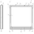
- (A) is a front view of the introductory window to which the hinge arm damper mechanism by one embodiment of this invention was applied
- (b) is a side view. It is a perspective view which shows the state which the shoji fell with respect to the window frame in the introductory window shown in FIG. It is a disassembled perspective view which shows the structure of the shoji falling angle locking mechanism used for the inverted window shown in FIG.
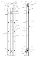
- (A) is a front view of the state which the locking member which comprises the shoji fall angle locking mechanism shown in FIG. 3 engaged with the upper hole
- (b) is a longitudinal cross-sectional view of the state.
- (A) is a front view of the state which the locking member which comprises the shoji fall angle locking mechanism shown in FIG.
- FIG. 7 is an exploded perspective view showing the structure of a hinge arm damper mechanism according to one embodiment.
- (A) is a side view of the hinge arm damper mechanism shown in FIG.
- (b) is a plan view
- (c) is a plan view showing the arrangement of each component in the state before operation of the hinge arm damper mechanism
- d) is a top view which shows arrangement
- FIG. 1 (a) is a front view and FIG. 1 (b) is a side view of an inverted window 2 to which a hinge arm damper mechanism 31, 31 described later according to one embodiment of the present invention is applied.
- the inward turning window 2 is configured by fitting the shoji 4 to the window frame 3.
- the window frame 3 includes a left vertical frame 3a standing vertically to the left, a right vertical frame 3b standing vertically to the right, an upper frame 3c connecting between the upper ends of the left vertical frame 3a and the right vertical frame 3b, and A lower frame 3d for connecting between the lower ends of the vertical frame 3a and the right vertical frame 3b is structured and configured.
- Shoji 4 has a left vertical weir 4a standing vertically to the left, a right vertical weir 4b standing vertically to the right, an upper weir 4c connecting between the upper ends of the left vertical weir 4a and the right vertical weir 4b, and a left vertical
- a lower rod 4d is formed in a frame so as to connect between the lower ends of the rod 4a and the right vertical rod 4b.
- the shoji 4 clamps the glass plate 5 between the left longitudinal weir 4a, the right longitudinal weir 4b, the upper weir 4c and the lower weir 4d.
- the window frame 3 and the shoji 4 are connected by hinge arms 6, 6 between the left vertical frame 3a and the left vertical weir 4a, and between the right vertical frame 3b and the right vertical weir 4b.
- FIG. 2 is a perspective view showing a state in which the sliding door 4 is supported by the hinges 6 and 6 connecting the window frame 3 and the sliding door 4 and the sliding door 4 is folded in half with respect to the window frame 3.
- the same reference numerals as in FIG. 1 denote the same parts in FIG.
- the upper edge 4c side of the shoji 4 is inclined to the indoor side centering on the side contacting the lower frame 3d of the lower edge 4d, and the predetermined angle is set by the lower edge locking mechanism 1,1 connected to each end of the hinge arms 6,6. It is kept in the fallen state.
- the shoji folding angle locking mechanism 1, 1 is the opposite surface of the left vertical hook 4a of the shoji 4 facing the left vertical frame 3a of the window frame 3, and the right vertical frame 3b of the window frame 3 Provided on the opposite surface facing the
- the respective shoji folding angle lock mechanisms 1, 1 have the same configuration, and hereinafter, only one provided on the left longitudinal weir 4 a of the shoji 4 will be described.
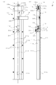
- FIG. 3 is an exploded perspective view showing the structure of the shoji fall angle lock mechanism 1.
- FIG. 4 (a) is a front view of the shoji fall angle lock mechanism 1
- FIG. 4 (b) is a longitudinal sectional view broken at the center line shown in FIG. 4 (a).
- the sliding door locking angle locking mechanism 1 includes the slide rail 11, the slide piece 12, the lock member 13, the lock spring 14 (see FIG. 4B), the lock release plate 15, the latch member 16, the latch spring 17, the rail cap 18, and The control lever 19 is provided.
- the slide rail 11 is made of an aluminum material, and is embedded in a slit formed on an opposing surface of the left vertical weir 4a facing the left vertical frame 3a, and attached to the left vertical weir 4a.
- the side plates of the left vertical weir 4a forming this slit are fastened to the mounting surfaces 11a and 11a of the slide rail 11 with five countersunk screws 20 respectively, and the side surfaces sandwiching the slide piece 12 of the slide rail 11 11b and 11b are flush with the side plate side surface of the left vertical weir 4a. Further, as shown in FIG.
- the rail cap 18 is attached to the upper rim 4c side end portion 11c of the shoji 4 of the slide rail 11 with two flathead screws 21 and 21, but the rail cap 18 has its upper end surface 18a. Is provided flush with the upper surface of the upper weir 4c.
- the two countersunk screws 21 and 21 are passed through the two through holes 18 b and 18 b formed in the rail cap 18 and screwed into the female screw holes 11 i and 11 i formed in the end 11 c of the slide rail 11.
- the rail cap 18 enclosed by blowing in FIG. 3 shows the state which looked down on the original rail cap 18 from diagonally opposite upper side.
- the slide rail 11 has tracks 11d and 11e extending along the longitudinal direction of the left vertical weir 4a and a slide surface 11f.
- the track 11d is constituted by a pair of opposed grooves formed in a wide width to face the columnar part forming the side surfaces 11b and 11b
- the track 11e is constituted by a pair of opposed grooves formed in a narrow width .
- the slide piece 12 linearly moves along the formation direction of the raceway 11d by fitting the pair of convex portions 12a, 12a formed on both sides to the groove of the raceway 11d.
- the lock release plate 15 linearly moves along the formation direction of the track 11 e by fitting the both sides thereof to the groove of the track 11 e.
- the slide surface 11f is formed on the surface facing the left vertical frame 3a of the connecting portion that connects between the columnar portions forming the side surfaces 11b and 11b, and is positioned at the back of the groove forming the tracks 11d and 11e.
- Holes 11g and 11h open at predetermined positions corresponding to the falling angle of the shoji 4 on the slide surface 11f.
- the upper hole 11g opens at a position corresponding to the middle tilt angle of the shoji 4 and the lower hole 11h opens at a position corresponding to the maximum tilt angle of the shoji 4.
- the slide piece 12 attached to the slide rail 11 so as to be movable along the track 11d is formed by aluminum die casting, and constitutes a slide member.
- the slide piece 12 pivotally supports one end of the hinge arm 6 on the side of the shoji 4 on a shaft portion 12b formed to project in a cylindrical shape on the side surface.
- One end of the hinge arm 6 is sandwiched by the resin washers 22 and 23, and a hole formed at the one end is passed through the shaft 12 b together with the resin washers 22 and 23.
- the truss screw 24 is screwed into the female screw formed in the shaft portion 12 b, and one end of the hinge arm 6 is prevented from coming off from the shaft portion 12 b together with the resin washers 22 and 23. It is swingably supported by the shaft portion 12b.
- the slide piece 12 moves the track 11 d in one direction away from the end 11 c by swinging one end of the hinge arm 6 by the weight of the hinge arm 6 when the shoji 4 is opened.
- the slide piece 12 has a cavity on the side facing the slide surface 11 f, and the lock member 13 is accommodated in the cavity.
- the lock member 13 is formed by aluminum die casting in the same manner as the slide piece 12.
- the lock member 13 is supported by a pair of holes 12c and 12c in which the pin 25 is passed through the through hole 13a formed at one end and the both ends of the pin 25 are opposed to the upper end side of the slide piece 12 Is rotatably attached to the slide piece 12.
- the lock member 13 has one end rotatably attached to the slide piece 12 in this manner, and moves the track 11 d in one direction together with the slide piece 12 with the other end at the top.
- a lock spring 14 is provided between the slide piece 12 and the lock member 13.
- One end of the lock spring 14 is fitted in a groove 13b provided in the abdomen of the lock member 13, and the other end of the lock member 13 is biased toward the slide surface 11f.
- the other end of the lock member 13 slides on the slide surface 11f when the slide piece 12 moves in one direction, and engages with the holes 11g and 11h formed in the slide surface 11f.
- the other end of the lock member 13 is inclined such that the angle in contact with the slide surface 11 f is acute.
- the holes 11 g and 11 h are formed in the slide surface 11 f along the slide direction in accordance with the plurality of tilt angles of the shoji 4.
- FIG. 4 shows a state in which the other end of the lock member 13 is engaged with the upper hole 11g
- FIG. 5 shows a state in which the other end of the lock member 13 is engaged with the lower hole 11h
- 5 (a) is a front view of the shoji fall angle lock mechanism 1 at this time
- FIG. 5 (b) is a longitudinal sectional view broken at the center line shown in FIG. 5 (a). The same code is attached.
- the other end of the lock member 13 engages with the holes 11g and 11h at a plurality of locations on the slide surface 11f, and the slide piece 12 is locked to a plurality of locations on the track 11d.
- one end of the hinge arm 6 is held at multiple angles at multiple levels.
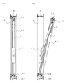
- 6 (a) shows the hinge arm 6 standing up and the window frame 3 being closed by the shoji 4.
- FIG. 6 (b) shows that the hinge arm 6 falls to an intermediate angle and the shoji 4 is half-opened.
- FIG. 7 shows a state in which the hinge arm 6 is at a maximum angle and the shoji 4 is fully open.
- the shoji 4 is held at a plurality of tilting angles by the hinge arm 6 and falls down in multiple steps, it is possible to select a plurality of opening amounts of the inward turning window 2.
- the lock release plate 15 is made of a stainless steel plate, and is guided by the track 11e and attached to the slide rail 11 so as to be movable along the slide surface 11f.
- the lock release plate 15 moves along the slide surface 11 f between the lock release position and the retraction position.
- the unlocking position is an operation position in which the tip 15a positioned at the front when the unlocking plate 15 moves in one direction pushes the other end of the locking member 13 engaged with the hole 11g from the hole 11g.
- the retreat position is an initial position where the tip 15a does not push up the other end of the lock member 13 from the hole 11g.
- the unlocking plate 15 shown in FIG. 4 and FIG. 5 shows the state in this retracted position.
- the latch spring 17 biases the lock release plate 15 along the slide surface 11 f to the retracted position.
- the rear end 15 b is provided to project from the rail cap 18 as shown in FIGS. 4 and 5.
- the rear end 15b of the unlocking plate 15 is bent to form a bent portion.
- the pin 26 is passed through the pair of holes formed in the bent portion and the through holes formed in the resin latch member 16, and the latch member 16 is attached to the rear end 15b by being pinched by the bent portion.
- the rear end 15b to which the latch member 16 is attached is retractably housed in a space 18c formed in a rectangular shape in the resin rail cap 18, and the side surfaces 18d and 18d are closed by the latch cover 18e.
- the attachment of the latch cover 18e to the side surfaces 18d, 18d is performed by a pair of countersunk screws 27, 27.
- a slide groove 18f is formed between the blocks forming the side faces 18d, 18d, and the portion directly below the rear end 15b of the lock release plate 15 is fitted into the slide groove 18f, and the movement of the lock release plate 15 is guided. Ru.
- the bent portion formed at the rear end 15b of the lock release plate 15 forms a first convex portion, and when the lock release plate 15 moves downward, contacts a surface 18g formed in a rectangular shape in the space 18c.
- the surface 18g abuts on a first convex portion provided on the rear end 15b of the lock release plate 15, and constitutes a surface that defines the lock release position of the lock release plate 15.
- convex portions 15c, 15c protruding to both sides are provided as second convex portions.
- the convex portions 15 c and 15 c abut on the bottom surface of the rail cap 18.
- the bottom surface of the rail cap 18 constitutes a surface that abuts on the second convex portion to define the retracted position of the lock release plate 15.
- the lock release plate 15 is guided by a slide groove 18 f formed in the rail cap 18 and a track 11 e formed in the slide rail 11 to move the slide surface 11 f.
- the unlocking plate 15 has a length such that the tip 15a reaches the hole 11g located closer to one of the plurality of holes 11g and 11h than the farthest hole 11h. Movement of the unlocking plate 15 in one direction against the biasing force of the latch spring 17 is provided at the rear end 15b of the unlocking plate 15 on the surface 18g of the rail cap 18 which determines the unlocking position of the unlocking plate 15. When the bent portion abuts, it is stopped at the unlocking position.
- the lock release plate 15 pushes up the other end of the lock member 13 engaged with the hole 11g from the hole 11g of the slide surface 11f to the hole 11g of the other end of the lock member 13 at the lock release position. Disengage the. Further, the movement of the unlocking plate 15 in the direction opposite to the one direction is achieved by the convex portions 15c, 15c of the unlocking plate 15 coming into contact with the bottom surface of the rail cap 18 which determines the retreat position of the unlocking plate 15. It is stopped at the retreat position, and the unlocking plate 15 is held at the retreat position by the biasing force of the latch spring 17.
- a columnar support 18 h is provided which is fitted to one end of the latch spring 17 to support one end thereof.
- the other end of the latch spring 17 abuts on the bottom surface of the latch member 16, and the elastic force causes the latch member 16 to project from the upper end surface 18 a of the rail cap 18, that is, the upper surface of the upper collar 4 c of the shoji 4.
- the latch member 16 is provided at the rear end 15b of the lock release plate 15 so that the surface on the outdoor side is curved so as to protrude from the outer shape of the rear end 15b of the lock release plate 15 as shown in FIGS. .
- the latch member 16 is urged in a direction to project from the upper rod 4c of the shoji 4 by the urging force of the latch spring 17, and the outer side surface of the latch member 16 abuts on the upper frame 3c of the window frame 3 when the shoji 4 is closed. As it is pushed down, it falls to the upper collar 4 c side of the shoji 4 and is accommodated in the space 18 c formed in the rail cap 18 together with the latch spring 17. Thereafter, when the latch member 16 reaches the latch receiver 29 (see FIG.
- the control lever 19 is formed by bending a stainless steel plate, and is extended from the lock release plate 15 to the indoor side as shown in FIG.
- the control lever 19 constitutes a lock release operating member that moves the lock release plate 15 along the slide surface 11 f to the lock release position against the biasing force of the latch spring 17.
- the unlocking plate 15 is always biased by the latch spring 17 and held at a retracted position where the leading end 15a located at the leading end does not reach the hole 11g when moving in one direction.
- the operation lever 19 is operated, and the unlocking plate 15 resists the biasing force of the latch spring 17 along the slide surface 11f.
- the tip end 15a of the unlocking plate 15 reaches the hole 11g located closer to one of the plurality of holes 11g and 11h than the farthest hole 11h. Then, the tip end 15a of the lock release plate 15 pushes up the other end of the lock member 13 from the hole 11g.
- the engagement state between the hole 11g excluding the hole 11h farthest from the unlocking plate 15 and the other end of the locking member 13 is thus the unlocking plate It can be solved by the fifteen tips 15a.
- each engagement state between each hole and the other end of the lock member 13 is one position closer than the hole 11 h farthest from the hole 11 g closest to the lock release plate 15 in the retracted position.
- the holes are released by the tip 15a of the unlocking plate 15 in the order of separation from the unlocking plate 15 in the retracted position.
- the falling angle shown in FIG. 7, which is determined by the position of the slide piece 12 engaged with the farthest hole 11 h and the other end of the lock member 13, is most inclined.
- one hinge arm 6 is connected to a hinge arm damper mechanism 31 shown in FIGS. 6 and 7 provided on the surface of the left vertical frame 3a of the window frame 3 facing the left vertical rod 4a of the shoji 4 It is done.
- the other end of the hinge arm 6 is connected to a similar hinge arm damper mechanism 31 provided on the surface of the right vertical frame 3b of the window frame 3 facing the right vertical rod 4b of the shoji 4.
- Each hinge arm 6, 6 has its rotational torque applied to the hinge arms 6, 6 buffered by the hinge arm damper mechanism 31, 31.
- FIG. 8 is an exploded perspective view of the hinge arm damper mechanism 31.
- FIG. 9 (a) is a side view of the hinge arm damper mechanism 31
- FIG. 9 (b) is a plan view
- FIG. 9 (c) is a plan view showing the arrangement of components before operation of the hinge arm damper mechanism 31.
- the same figure (d) is a top view which shows arrangement
- the hinge arm damper mechanism 31 includes a pinion gear 32, a pair of racks 33, 33, two sets of heavy load springs 34, 34, a pair of slide bars 35, 35, and a housing.
- the housing comprises a box-like case 36 and a plate-like cover 37.
- the pinion gear 32, the pair of racks 33, 33, the two sets of heavy load springs 34, 34, and the pair of slide bars 35, 35 are shown in FIGS. It is stored.
- a cover 37 is attached to a case 36 containing these components by a countersunk screw 38a and a countersunk screw 38b, and the components are sealed as shown in FIGS. 9 (a) and 9 (b).
- the pinion gear 32 is rotatably supported by the housing by the shaft portions 32a on both sides fitted into the opening 37a of the cover 37 and the opening 36e of the case 36.
- the opening 37a and the opening 36e constitute a gear support.
- a hexagonal columnar connecting portion 32 b is formed coaxially with the shaft portion 32 a on the side shaft portion 32 a on the cover 37 side.
- the other end of the hinge arm 6 is fitted to the connecting portion 32b, and the hinge arm 6 rotates around the other end.
- the pair of racks 33, 33 are provided at positions facing each other across the rotation center of the pinion gear 32, and, upon receiving the rotation of the pinion gear 32, go straight in the direction away from each other.
- the racks 33, 33 mesh with the pinion gear 32 to convert the rotational movement of the pinion gear 32 into a linear movement.
- guide portions 36a, 36a for guiding the rectilinear movement of the racks 33, 33 are formed by the inner wall of the case 36 in contact with the side surfaces of the racks 33, 33.
- a plurality of reinforcing ribs 36d are formed on the outer side of the case 36 where the guide portions 36a and 36a are formed, in a direction intersecting the direction of the linear movement of the racks 33 and 33.
- the racks 33, 33 have extending portions 33a, 33a in a direction intersecting with the direction in which the racks 33 move straight.
- a slide bar 35 and springs 34, 34 are accommodated between the extensions 33a, 33a and the end walls 36b, 36b of the case 36.
- Each slide bar 35 is formed in parallel with the extension 33a, and a contact surface 35a that contacts the extension 33a is formed on the rack 33 side. Further, fitting portions 35b, 35b fitted to one end portions of the springs 34, 34 are formed side by side on the springs 34, 34 side.
- Each slide bar 35 constitutes a restricting member disposed between the extension 33 a and one end of each spring 34, 34.
- Each pair of springs 34 and 34 is provided at a position opposite to each other with the racks 33 and 33 centered on the rotation center of the pinion gear 32.
- the springs 34, 34 are formed by compression coil springs, and constitute elastic members that brake the rectilinear movement of the racks 33, 33 in the separating direction.
- Each spring 34 receives the force of movement of the rack 33 at one end from the extension 33 a through the slide bar 35.
- the end wall 36 b of the case 36 constitutes a reaction force support portion, and receives a reaction force generated on the springs 34 by braking the linear movement of the rack 33.
- two springs 34 are provided in parallel, and the motion force of the rack 33 is shared and received at each one end of the springs 34, 34.
- the springs 34, 34 are separated by a partition 36c of the case 36 to prevent buckling.
- the rotational torque applied to the hinge arm 6 is transmitted to the racks 33, 33 via the rotational movement of the pinion gear 32, and converted into the linear movement of the racks 33, 33.
- This linear movement of the racks 33, 33 is braked by the springs 34, 34. Therefore, the rotational torque applied to the hinge arm 6 is reliably buffered by the braking force of the springs 34, 34. Therefore, by applying the hinge arm damper mechanism 31 having the above configuration to the hinge arm 6 of the inverted window 2, it is possible to reliably exhibit the damper effect according to the braking force of the springs 34, 34. Therefore, even if the shoji 4 is large and heavy, an appropriate damper effect is exhibited, and it is possible to sufficiently buffer the rotational torque applied to the hinge arm 6 of the inverted window 2.
- braking force of the spring 34,34 is exhibited according to the deflection amount. Therefore, as shown in FIG. 6B, when the amount of rotation of the hinge arm 6 is small, the distance that the racks 33 and 33 move straight is short and the amount of deflection generated in the springs 34 and 34 is small. The power is small and the force to buffer the rotational torque applied to the hinge arm 6 is weak. On the other hand, when the amount of rotation of the hinge arm 6 increases to the maximum inclination angle of the shoji 4 shown in FIG. 7, the straight distance of the racks 33 and 33 goes straight and the deflections of the springs 34 and 34 increase. The braking forces of the springs 34 and 34 gradually increase, and the force for buffering the rotational torque applied to the hinge arm 6 gradually increases.
- the hinge arm damper mechanism 31 according to the present embodiment to the hinge arm 6 of the inverted window 2, when the amount of opening of the shoji 4 is small and the amount of rotation of the hinge arm 6 is small Although the force is weak, as the opening amount of the shoji 4 increases and the falling angle of the shoji 4 increases, the amount of rotation of the hinge arm increases, and the assisting force for the opening and closing operation of the shoji gradually becomes stronger. Therefore, when opening the shoji 4, the operating force that is increased by the weight of the shoji 4 when opening the shoji 4 can be a light operating force by the assisting force of the hinge arm damper mechanism 31.
- the biasing force of the springs 34 and 34 is added to the operation force for closing the shoji 4 so that the shoji 4 can be closed with a light operation force. Therefore, the operator of the shoji 4 can perform the opening and closing operation of the shoji 4 with a good feeling of operation.
- the damper effect is constant when the shoji 4 is opened and closed because the damper effect is obtained by the resin washer or the wave washer sandwiched by the shaft. For this reason, when closing the shoji 4, operation becomes heavy by damper effects, such as a resin washer, and the operativity with the good feeling of operation like the hinge arm damper mechanism 31 by this embodiment is not obtained.
- the hinge arm damper mechanism 31 since the racks 33 and 33 and the springs 34 and 34 are symmetrically provided at positions facing each other about the rotation center of the pinion gear 32, the rotational movement of the pinion gear 32 is It is converted in a well-balanced manner into linear motion of the racks 33, 33. Therefore, the buffer operation of the hinge arm damper mechanism 31 is stably performed. Further, since the buffer function acts on both sides of the position opposite to the center of rotation of the pinion gear 32, the buffer force is enhanced, and the large rotational torque applied to the hinge arm 6 can be buffered.
- the hinge arm damper mechanism 31 according to the present embodiment, the kinetic force of the racks 33 is stably transmitted to one end of the springs 34 via the extending portions 33a. Therefore, the rotational torque applied to the hinge arm 6 is effectively transmitted to the springs 34 and 34 through the racks 33 and 33, and the braking force of the springs 34 and 34 effectively acts to rotate the hinge arm 6 The torque is more reliably buffered.
- two springs 34, 34 are provided in parallel, and the braking force exerted by the springs 34, 34 in general becomes stronger. It can buffer torque.
- the hinge arm damper mechanism 31 according to the present embodiment, the kinetic force of the racks 33, 33 from the extending portions 33a, 33a is reliably received by the contact surfaces 35a, 35a of the slide bars 35, 35, By the fitting portions 35b of the slide bars 35, the arrangement position is reliably transmitted to one end of each of the springs 34, which are regulated and held side by side. Therefore, the braking force of the springs 34, 34 acts more effectively on the racks 33, 33, and the rotational torque applied to the hinge arm 6 is buffered more reliably.
- the racks 33, 33 receive the guidance from the guide portions 36a, 36a of the case 36 constituting the casing and convert the rotational movement of the pinion gear 32 into a rectilinear movement, but the racks 33, 33 correspond to the guide portions 36a, 36a.
- a reaction force is applied which restricts this linear movement, and a force acts on the guide portions 36a and 36a to distort the housing.
- the reinforcing ribs 36d and 36d are formed on the outer side of the portion where the guide portions 36a and 36a of the housing are formed, and the reinforcing ribs 36d and 36d serve as the housing Opposed to the distorting force. For this reason, even if a force to distort the case is applied to the case from the racks 33, 33, deformation of the case is prevented, and the rotational movement of the pinion gear 32 is surely converted to the linear movement of the racks 33, 33.
- the reinforcing ribs 36d and 36d are formed to rise in the direction perpendicular to the linear movement direction of the racks 33, 33. However, a direction parallel to the linear movement direction of the racks 33 and 33 is described. You may make it form the reinforcement rib which swells up.
- an adjustment member for adjusting the initial braking force of the springs 34, 34 may be provided on the other end side or one end side of the springs 34, 34.
- an adjustment member for example, a plate, a washer, or the like provided on the end walls 36 b and 36 b of the case 36 with the springs 34 and 34 may be mentioned.
- the end wall 36b side of the partition wall 36c is partially removed over a predetermined length, and the position of the plate material abutting on both ends of the springs 34, 34 can be varied in the extension direction of the springs 34, 34. It can also be configured.
- the shock absorbing force exerted by the hinge arm damper mechanism 31 can be easily set to a desired shock absorbing force by adjusting the initial braking force of the springs 34 by the adjusting member. For this reason, it becomes possible to adjust easily to the hinge arm damper mechanism 31 which exhibits the required damper effect.
- the hinge arm damper mechanism 31 the case where two springs 34 and 34 are provided in parallel is described, but three or more springs may be provided in parallel instead of in parallel. It may be configured as follows. In the case where the rack 33 is provided independently, by leaving the spring 34 on the root side of the extension 33a of the rack 33, the rack 33 can receive the rectilinear motion of the rack 33 without tilting, and the efficiency is improved. Power is transmitted to Further, in the hinge arm damper mechanism 31 according to the above embodiment, the respective sets of the springs 34, 34 are provided symmetrically at the opposing position centering on the pinion gear 32, but not provided symmetrically, only on one side of the pinion gear 32. A plurality of or one spring 34 may be provided.
Landscapes
- Engineering & Computer Science (AREA)
- Mechanical Engineering (AREA)
- Closing And Opening Devices For Wings, And Checks For Wings (AREA)
- Wing Frames And Configurations (AREA)
Abstract
弾性部材の制動力に応じたダンパ効果を確実に発揮させられるヒンジアームダンパ機構を提供する。ヒンジアームダンパ機構31は、ピニオンギヤ32、一対のラック33,33、2組の重荷重スプリング34,34、一対のスライドバー35,35、および筐体を備えて構成される。筐体は、箱状をしたケース36および板状をしたカバー37からなる。ケース36には、上記のピニオンギヤ32、一対のラック33,33、2組の重荷重スプリング34,34、および一対のスライドバー35,35が収納される。ヒンジアーム6にかかる回転トルクは、ピニオンギヤ32の回転運動を介してラック33,33に伝達され、ラック33,33の直進運動に変換される。ラック33,33のこの直進運動は各スプリング34,34によって確実に制動がかけられる。
Description
本発明は、ヒンジアームにかかる回転トルクを緩衝するヒンジアームダンパ機構に関するものである。
従来この種のヒンジアームダンパ機構として、例えば、内倒し窓に使用されるものがある。内倒し窓では、窓枠および障子間がヒンジアームによって連結され、ヒンジアームダンパ機構により、障子の重量等によってヒンジアームにかかる回転トルクが緩衝される。
例えば、特許文献1に開示された内倒し窓では、第一アーム、第二アームおよび連結軸を具備する連結部がヒンジアームを構成し、窓枠と障子とが連結部によって連結される。第一アームは、その一端が第一回動軸を介して窓枠に前後に回動可能に連結される。第二アームは、その一端が第二回動軸を介して障子に前後に回動可能に連結される。連結軸は、第一アームの下端と第二アームの下端とを、互いに前後に回動可能となるように連結する。このようなヒンジアームについてのヒンジアームダンパ機構は、従来、第一回動軸、第二回動軸および連結軸に樹脂ワッシャーあるいはウエーブワッシャーが挟み込まれて構成される。各軸に挟み込まれる樹脂ワッシャーあるいはウエーブワッシャーは、第一回動軸、第二回動軸および連結軸の各回動に抵抗力を発生させ、障子の重量等によってヒンジアームにかかる回転トルクを緩衝する。
しかしながら、上記従来のようなヒンジアームダンパ機構では、障子が大型で重量があると、ダンパ効果が弱く、ヒンジアームにかかる回転トルクを十分に緩衝することができない。
本発明はこのような課題を解決するためになされたもので、
ヒンジアームにかかる回転トルクを緩衝するヒンジアームダンパ機構において、
ヒンジアームの回転中心にヒンジアームに連結して設けられるピニオンギヤと、
ピニオンギヤに噛み合ってピニオンギヤの回転運動を直進運動に変換するラックと、
ラックの直進運動に制動をかける弾性部材と、
ピニオンギヤを回転自在に支持するギヤ支持部、ラックの直進運動をガイドするガイド部、および、ラックの直進運動に制動をかけることで弾性部材に生じる反力を受ける反力支持部を有して、ピニオンギヤ、ラックおよび弾性部材を収容する筐体と
を備えることを特徴とする。
ヒンジアームにかかる回転トルクを緩衝するヒンジアームダンパ機構において、
ヒンジアームの回転中心にヒンジアームに連結して設けられるピニオンギヤと、
ピニオンギヤに噛み合ってピニオンギヤの回転運動を直進運動に変換するラックと、
ラックの直進運動に制動をかける弾性部材と、
ピニオンギヤを回転自在に支持するギヤ支持部、ラックの直進運動をガイドするガイド部、および、ラックの直進運動に制動をかけることで弾性部材に生じる反力を受ける反力支持部を有して、ピニオンギヤ、ラックおよび弾性部材を収容する筐体と
を備えることを特徴とする。
本構成によれば、ヒンジアームにかかる回転トルクは、ピニオンギヤの回転運動を介してラックに伝達され、ラックの直進運動に変換される。ラックのこの直進運動は弾性部材によって制動がかけられる。したがって、ヒンジアームにかかる回転トルクは、弾性部材の制動力によって確実に緩衝される。このため、本構成をしたヒンジアームダンパ機構を内倒し窓等のヒンジアームに適用することで、弾性部材の制動力に応じたダンパ効果を確実に発揮させることができる。よって、障子が大型で重量があっても、適切なダンパ効果が奏され、内倒し窓等のヒンジアームにかかる回転トルクを十分に緩衝することが可能になる。
また、本発明は、弾性部材が圧縮コイルバネであることを特徴とする。
本構成によれば、弾性部材の制動力は圧縮コイルバネのたわみ量に応じて発揮される。したがって、ヒンジアームの回転量が小さいときには、ラックの直進する距離が短く、圧縮コイルバネに生じるたわみ量が小さいので、弾性部材の制動力が小さく、ヒンジアームにかかる回転トルクを緩衝する力は弱い。一方、ヒンジアームの回転量が増えていくと、ラックの直進する距離が次第に長くなり、圧縮コイルバネに生じるたわみ量が大きくなるので、弾性部材の制動力が次第に大きくなって、ヒンジアームにかかる回転トルクを緩衝する力は次第に強くなる。
このため、本構成をしたヒンジアームダンパ機構を内倒し窓等のヒンジアームに適用することで、障子の開ける量が少なくてヒンジアームの回転量が小さいときには、障子開閉操作に対する補助力が弱いが、障子の開ける量が多くなって、障子の倒れる角度が大きくなるのに連れて、ヒンジアームの回転量が大きくなり、障子開閉操作に対する補助力が次第に強くなる。よって、障子を開けるときに、障子を開けるのに連れて障子の重量によって重くなる操作力は、ヒンジアームダンパ機構の補助力によって軽い操作力で済むようになる。また、障子を閉めるときには、弾性部材の付勢力が障子を閉める操作力に加わり、軽い操作力で障子を閉めることができるようになる。このため、障子の操作者は、操作感良く障子の開閉操作を行えるようになる。
これに対して、上述した従来のようなヒンジアームダンパ機構では、軸に挟み込む樹脂ワッシャーあるいはウエーブワッシャーによってダンパ効果を得るため、障子を開けるときと閉めるときとでダンパ効果は一定になる。このため、障子を閉めるときに樹脂ワッシャー等のダンパ効果によって操作が重くなってしまい、本構成のヒンジアームダンパ機構のような操作感の良い操作性は得られない。
また、本発明は、
ラックが、ピニオンギヤの回転中心を挟んで対向する位置に一対設けられ、ピニオンギヤの回転を受けて互いに離反する方向に直進し、
弾性部材が、ピニオンギヤの回転中心を中心に各ラックを介する対向位置に一対設けられ、各ラックの離反する方向への直進運動に制動をかける
ことを特徴とする。
ラックが、ピニオンギヤの回転中心を挟んで対向する位置に一対設けられ、ピニオンギヤの回転を受けて互いに離反する方向に直進し、
弾性部材が、ピニオンギヤの回転中心を中心に各ラックを介する対向位置に一対設けられ、各ラックの離反する方向への直進運動に制動をかける
ことを特徴とする。
本構成によれば、ラックおよび弾性部材がピニオンギヤの回転中心を中心に対向する位置に対称に一対設けられるので、ピニオンギヤの回転運動はラックの直進運動にバランス良く変換される。したがって、ヒンジアームダンパ機構の緩衝動作は安定して行われる。また、ピニオンギヤの回転中心を中心に対向する位置の両側で緩衝機能が作用するので緩衝力が高まり、ヒンジアームにかかる大きな回転トルクを緩衝することができる。
また、本発明は、
ラックが、直進する方向に交差する方向に延出部を有し、
弾性部材が延出部から一端部にラックの運動力を受ける
ことを特徴とする。
ラックが、直進する方向に交差する方向に延出部を有し、
弾性部材が延出部から一端部にラックの運動力を受ける
ことを特徴とする。
本構成によれば、ラックの運動力は延出部を介して安定して弾性部材の一端部へ伝えられる。このため、ヒンジアームにかかる回転トルクはラックを介して効果的に弾性部材へ伝えられ、弾性部材の制動力が効果的に作用して、ヒンジアームにかかる回転トルクはより確実に緩衝される。
また、本発明は、弾性部材が、複数個並列に設けられて各一端部にラックの運動力を分担して受けることを特徴とする。
本構成によれば、弾性部材の総じて発揮する制動力が強くなるので、ヒンジアームにかかるより大きな回転トルクを緩衝することができる。
また、本発明は、延出部と平行に形成されて延出部に当接する当接面がラック側に形成され、各弾性部材の一端部に嵌まる嵌合部が弾性部材側に並んで形成されて、延出部と各弾性部材の一端部との間に配置される規制部材を備えることを特徴とする。
本構成によれば、延出部からのラックの運動力は規制部材の当接面に確実に受け止められて、規制部材の嵌合部により配置位置が並んで規制保持される各弾性部材の一端部に確実に伝達される。このため、弾性部材の制動力がより効果的にラックに作用して、ヒンジアームにかかる回転トルクはより確実に緩衝される。
また、本発明は、筐体のガイド部が形成される部分の外側部に、ラックの直進運動方向と交差する方向、または、ラックの直進運動方向と平行な方向に盛り上がる補強リブが形成されることを特徴とする。
ラックは筐体のガイド部の案内を受けてピニオンギヤの回転運動を直進運動に変換するが、ガイド部にはラックのこの直進運動を規制する反力がかかり、ガイド部に筐体を歪める力が作用する。しかし、本構成によれば、筐体のガイド部が形成される部分の外側部に補強リブが形成され、補強リブが筐体を歪める力に対向する。このため、筐体を歪める力がラックから筐体にかかっても、筐体の変形が防がれ、ピニオンギヤの回転運動が確実にラックの直進運動に変換される。
また、本発明は、弾性部材の初期制動力を調整する調整部材を弾性部材の他端部側または一端部側に備えることを特徴とする。
本構成によれば、調整部材によって弾性部材の初期制動力を調整することで、ヒンジアームダンパ機構の発揮する緩衝力を容易に所望の緩衝力に設定することができる。このため、必要とされるダンパ効果を奏するヒンジアームダンパ機構に容易に調整することが可能になる。
本発明によれば、弾性部材の制動力に応じたダンパ効果を確実に発揮させられるヒンジアームダンパ機構を提供することができ、内倒し窓等のヒンジアームに適用することで、障子が大型で重量があっても、ヒンジアームにかかる回転トルクを十分に緩衝することが可能になる。
次に、本発明によるヒンジアームダンパ機構を内倒し窓に適用した一実施の形態について説明する。
図1(a)は、本発明の一実施形態による後述するヒンジアームダンパ機構31,31が適用された内倒し窓2の正面図、同図(b)は側面図である。
内倒し窓2は窓枠3に障子4が嵌められて構成されている。窓枠3は、左方に垂直に立つ左縦枠3a、右方に垂直に立つ右縦枠3b、左縦枠3aおよび右縦枠3bの各上端間を連結する上枠3c、並びに、左縦枠3aおよび右縦枠3bの各下端間を連結する下枠3dが枠組みされて構成されている。障子4は、左方に垂直に立つ左縦框4a、右方に垂直に立つ右縦框4b、左縦框4aおよび右縦框4bの各上端間を連結する上框4c、並びに、左縦框4aおよび右縦框4bの各下端間を連結する下框4dが枠組みされて構成されている。障子4は、これら左縦框4a、右縦框4b、上框4cおよび下框4d間にガラス板5を挟持している。窓枠3および障子4間は、左縦枠3aおよび左縦框4a間、並びに、右縦枠3bおよび右縦框4b間がそれぞれヒンジアーム6,6により連結されている。
図2は、窓枠3および障子4間を連結するヒンジアーム6,6により支持されて、窓枠3に対して障子4が半開きに倒れた状態を示す斜視図である。なお、同図において図1と同一部分には同一符号を付してその説明は省略する。
障子4は、下框4dの下枠3dに接する辺を中心に上框4c側が室内側に倒れ、ヒンジアーム6,6の各一端に連結された障子倒れ角ロック機構1,1により、所定角度に倒れた状態に保持される。障子倒れ角ロック機構1,1は、障子4の左縦框4aにおける窓枠3の左縦枠3aに対向する対向面、並びに、障子4の右縦框4bにおける窓枠3の右縦枠3bに対向する対向面に設けられる。各障子倒れ角ロック機構1,1は同じ構成をしており、以下、障子4の左縦框4aに設けられる一方のみについて説明する。
図3は、障子倒れ角ロック機構1の構造を示す分解斜視図である。図4(a)は障子倒れ角ロック機構1の正面図、同図(b)は同図(a)に示す中心線で破断した縦断面図である。
障子倒れ角ロック機構1は、スライドレール11、スライド駒12、ロック部材13、ロックスプリング14(図4(b)参照)、ロック解除板15、ラッチ部材16、ラッチスプリング17、レールキャップ18、および操作レバー19を備えて構成される。
スライドレール11は、アルミニウム材からなり、左縦框4aにおける左縦枠3aに対向する対向面に形成されたスリットに埋め込まれて、左縦框4aに取り付けられる。この際、このスリットを形成する左縦框4aの側板が、スライドレール11の一段落ち込んだ取付面11a,11aにそれぞれ5本の皿ねじ20で締結され、スライドレール11のスライド駒12を挟む側面11b,11bが左縦框4aの側板側面と面一になる。また、スライドレール11の障子4の上框4c側端部11cには、図4に示すようにレールキャップ18が2本の皿ねじ21,21で取り付けられるが、レールキャップ18はその上端面18aが上框4cの上面と面一に設けられる。2本の皿ねじ21,21は、レールキャップ18に形成された2つの貫通穴18b,18bに通されて、スライドレール11の端部11cに形成された雌ねじ穴11i,11iに螺合する。なお、図3において吹き出しに囲まれたレールキャップ18は、元のレールキャップ18を反対側の斜め上方から見下ろした状態を示す。
スライドレール11は、左縦框4aの長手方向に沿って延びる軌道11d,11eおよびスライド面11fを有している。軌道11dは、側面11b,11bを形成する柱状部に対向して広い幅に形成された対向する一対の溝によって構成され、軌道11eは狭い幅に形成された対向する一対の溝によって構成される。スライド駒12は、その両側部に突出して形成された一対の凸部12a,12aが軌道11dの溝に嵌合することで、軌道11dの形成方向に沿って直動する。また、ロック解除板15は、その両側部が軌道11eの溝に嵌合することで、軌道11eの形成方向に沿って直動する。
スライド面11fは、側面11b,11bを形成する柱状部間を連結する連結部の、左縦枠3aに対向する面に形成され、軌道11d,11eを構成する溝の奥に位置する。スライド面11fには、障子4の倒れ角に応じた所定位置に孔11g,11hが開口している。上方の孔11gは障子4の中間倒れ角に応じた位置、下方の孔11hは障子4の最大倒れ角に応じた位置に開口している。
軌道11dに沿って移動自在にスライドレール11に取り付けられるスライド駒12は、アルミダイキャストによって成形されており、スライド部材を構成する。スライド駒12は、側面に円柱状に突出して形成された軸部12bに、ヒンジアーム6の障子4側の一端を揺動自在に支持する。ヒンジアーム6の一端は、樹脂ワッシャ22,23に挟まれて、その一端に形成された孔が樹脂ワッシャ22,23と共に軸部12bに通される。そして、トラスねじ24が軸部12bに形成された雌ねじに螺合し、樹脂ワッシャ22,23と共にヒンジアーム6の一端が軸部12bから抜けるのが防止されることで、ヒンジアーム6の一端は軸部12bに揺動自在に支持される。スライド駒12は、障子4が開けられるときに、ヒンジアーム6の自重によってヒンジアーム6の一端が揺動することにより、軌道11dを端部11cから離れる一方向に移動する。
スライド駒12はスライド面11fに向かう側に空洞を有し、ロック部材13はこの空洞に収容される。ロック部材13は、スライド駒12と同様にアルミダイキャストによって成形される。ロック部材13は、一端に形成された貫通孔13aにピン25が通され、ピン25の両端がスライド駒12の上端側に対向して形成された一対の孔12c,12cに支持されて、一端が回動自在にスライド駒12に取り付けられる。ロック部材13は、一端がこのようにスライド駒12に回動自在に取り付けられることで、他端を先頭にスライド駒12と共に軌道11dを一方向に移動する。
スライド駒12およびロック部材13間には、ロックスプリング14が設けられている。ロックスプリング14の一端部はロック部材13の腹部に設けられた溝13bに嵌まり、ロック部材13の他端をスライド面11fに向けて付勢する。この付勢により、ロック部材13の他端は、スライド駒12の一方向への移動時にスライド面11fを摺接し、スライド面11fに形成された孔11g,11hに係合する。ロック部材13の他端は、スライド面11fに接する角が鋭角になるように傾斜がつけられている。孔11g,11hは、障子4の複数の倒れ角に応じてスライド面11fにスライド方向に沿って複数形成されている。
図4はロック部材13の他端が上方の孔11gに係合した状態を示し、図5はロック部材13の他端が下方の孔11hに係合した状態を示している。図5(a)はこのときにおける障子倒れ角ロック機構1の正面図、同図(b)は同図(a)に示す中心線で破断した縦断面図であり、図4と同一部分には同一符号を付してある。
本実施形態では、上記のように、ロック部材13の他端がスライド面11fの複数箇所で孔11g,11hと係合し、スライド駒12が軌道11dの複数箇所に係止するので、図6(a)、(b)および図7の側面図に示すように、ヒンジアーム6の一端は複数の角度に多段階に保持される。図6(a)は、ヒンジアーム6が起立して窓枠3が障子4で塞がれている状態、同図(b)は、ヒンジアーム6が中間角度に倒れて障子4が半開きになっている状態、図7は、ヒンジアーム6が最大角度に倒れて障子4が全開になっている状態を示す。このように障子4はヒンジアーム6によって複数の倒れ角に保持されて多段階に倒れるので、内倒し窓2の開放量は複数選択することが可能になる。
ロック解除板15は、ステンレス板から成り、軌道11eに案内されてスライド面11fに沿って移動自在にスライドレール11に取り付けられる。このロック解除板15はロック解除位置と待避位置との間をスライド面11fに沿って移動する。ロック解除位置は、ロック解除板15の一方向への移動時に先頭に位置する先端15aが、孔11gに係合したロック部材13の他端を孔11gから押し上げる作動位置である。また、待避位置は、先端15aが、ロック部材13の他端を孔11gから押し上げない初期位置である。図4および図5に示すロック解除板15はこの待避位置にある状態を示している。ラッチスプリング17は、ロック解除板15をスライド面11fに沿って待避位置へ付勢する。ロック解除板15が待避位置にあるとき、その後端15bは、図4および図5に示すように、レールキャップ18から突出するように設けられる。
ロック解除板15は、図3に示すように後端15bが曲げ加工されて、曲げ部が形成されている。この曲げ部に形成された一対の孔、および樹脂製のラッチ部材16に形成された貫通孔にピン26が通されて、曲げ部に挟まれてラッチ部材16が後端15bに取り付けられる。ラッチ部材16が取り付けられた後端15bは、樹脂製のレールキャップ18に矩形状に形成された空間18cに出没自在に収容され、側面18d,18dがラッチカバー18eで塞がれる。ラッチカバー18eの側面18d,18dへの取り付けは一対の皿ねじ27,27によって行われる。また、側面18d,18dを形成するブロック間にはスライド溝18fが形成され、ロック解除板15の後端15bの直下部分がこのスライド溝18fに嵌まって、ロック解除板15の移動が案内される。
ロック解除板15の後端15bに形成された曲げ部は第1凸部を形成し、ロック解除板15が下方へ移動すると、空間18cに矩形状に形成された面18gに当接する。面18gは、ロック解除板15の後端15bに設けられた第1凸部に当接して、ロック解除板15のロック解除位置を定める面を構成する。また、ロック解除板15の腹部には両脇に突出する凸部15c,15cが第2凸部として設けられている。ロック解除板15が上方へ移動すると、凸部15c,15cがレールキャップ18の底面に当接する。レールキャップ18の底面は、第2凸部に当接してロック解除板15の待避位置を定める面を構成する。
ロック解除板15は、レールキャップ18に形成されたスライド溝18fおよびスライドレール11に形成された軌道11eに案内されて、スライド面11fを移動する。ロック解除板15は、複数の孔11g,11hのうちの最も離れた孔11hよりも1つ近い位置にある孔11gに先端15aが達する長さを有する。ラッチスプリング17の付勢力に抗するロック解除板15の一方向への移動は、ロック解除板15のロック解除位置を定めるレールキャップ18の面18gに、ロック解除板15の後端15bに設けられた曲げ部が当接することで、ロック解除位置で止められる。ロック解除板15は、このロック解除位置で、その先端15aが、孔11gに係合したロック部材13の他端をスライド面11fの孔11gから押し上げて、ロック部材13の他端の孔11gへの係合を解く。また、ロック解除板15の一方向と逆の方向への移動は、ロック解除板15の待避位置を定めるレールキャップ18の底面に、ロック解除板15の凸部15c,15cが当接することで、待避位置で止められ、ロック解除板15は、ラッチスプリング17の付勢力によって待避位置に保持される。
レールキャップ18に形成される空間18cの底面には、ラッチスプリング17の一端に嵌まってその一端を支持する柱状の支持部18hが設けられている。ラッチスプリング17の他端はラッチ部材16の底面に当接し、その弾性力により、ラッチ部材16をレールキャップ18の上端面18aすなわち障子4の上框4c上面から突出させる。
ラッチ部材16は、図4および図5に示すように、ロック解除板15の後端15bの外形からはみ出して、室外側の面が湾曲してロック解除板15の後端15bに設けられている。ラッチ部材16は、ラッチスプリング17の付勢力によって障子4の上框4cから突出する方向に付勢され、障子4が閉められるときに室外側の面が窓枠3の上枠3cに当接して押されて、障子4の上框4c側に落ち込み、レールキャップ18に形成された空間18cにラッチスプリング17と共に収容される。その後、ラッチ部材16は、障子4が閉められて窓枠3の上枠3cに形成された被係合部を構成するラッチ受け29(図6参照)に達すると、ラッチスプリング17の付勢力によって障子4の上框4cから突出して、図6(a)に示すようにラッチ受け29に係合する。
ロック解除板15に形成された凸部15c,15cの下方には、2つの孔15d,15dが形成されている。この孔15d,15dに2つの皿ねじ28,28が通されて、操作レバー19の端部に形成された2つの雌ねじ孔19a,19aに皿ねじ28,28が螺合することで、ロック解除板15に操作レバー19の端部が固定される。操作レバー19は、ステンレス板が曲げ加工されて形成され、ロック解除板15から図2に示すように室内側に延出して設けられる。操作レバー19は、ラッチスプリング17の付勢力に抗してロック解除板15をスライド面11fに沿ってロック解除位置へ移動させるロック解除操作部材を構成する。ラッチ部材16のラッチ受け29への係合は、ラッチスプリング17の付勢力に抗して操作レバー19が一方向に操作されて、ラッチ部材16が障子4の上框4c側に落ち込まないと、解除されない。したがって、ラッチ部材16のラッチ受け29への係合により、窓枠3は障子4によって閉鎖した状態に保持される。
このような構成をした障子倒れ角ロック機構1は、障子4が開けられるとき、ヒンジアーム6の一端がヒンジアーム6の自重によって揺動して、ヒンジアーム6の一端を揺動自在に支持するスライド駒12がスライドレール11の軌道11dを下方の一方向に移動する。この際、スライド駒12に一端が回動自在に取り付けられたロック部材13は、その他端がロックスプリング14によってスライドレール11のスライド面11fに向けて付勢され、スライド面11fを摺接する。障子4が所定角度に倒れると、ロック部材13の他端は、スライド面11fに開口した孔11g,11hに嵌まって、この孔11g,11hに係合する。したがって、スライド駒12の一方向への移動が阻止され、スライド駒12に一端が支持されるヒンジアーム6は、図6および図7に示すように、スライド駒12の移動が阻止された位置に保持され、ヒンジアーム6に支持される障子4は所定角度に倒れた状態に保持される。
ロック解除板15は、常時、ラッチスプリング17に付勢されて、一方向への移動時に先頭に位置する先端15aが孔11gに達しない待避位置に保持されている。障子4が図6(b)に示すような所定角度に倒れた状態で、操作レバー19が操作されて、ロック解除板15がラッチスプリング17の付勢力に抗してスライド面11fに沿って一方向へ移動させられると、ロック解除板15の先端15aが複数の孔11g,11hのうちの最も離れた孔11hよりも1つ近い位置にある孔11gに達する。そして、ロック解除板15の先端15aはロック部材13の他端を孔11gから押し上げる。スライド面11fに複数形成された孔11g,11hのうちの、ロック解除板15から最も離れた孔11hを除く孔11gとロック部材13の他端との係合状態は、このようにロック解除板15の先端15aによって解くことができる。
本実施形態ではスライド面11fに2つの孔11g,11hがある場合について説明しているが、孔11g,11hの間のスライド面11fにさらに図示しない孔があって3つ以上の孔がある場合でも、各孔とロック部材13の他端との各係合状態は、待避位置にあるロック解除板15に最も近い位置にある孔11gから、最も離れた孔11hよりも1つ近い位置にある孔まで、待避位置にあるロック解除板15から離れる順に、ロック解除板15の先端15aによって解除される。このため、障子4は、最も離れた孔11hとロック部材13の他端とが係合するスライド駒12の位置によって定まる、図7に示す倒れ角度が、最も倒れた状態になる。最も離れた孔11hとロック部材13の他端との係合状態は、倒れた障子4を起こしてヒンジアーム6の一端を逆方向へ揺動させ、スライド駒12が一方向と逆の方向へスライド面11fに沿ってスライドして、ロック部材13の他端が最も離れた孔11hを上滑りすることで、解除される。その後、倒れた障子4をさらに起こしていくことで、ロック部材13の他端は、ヒンジアーム6の一端の逆方向へのさらなる揺動に伴うスライド駒12の逆方向へのスライドにより、最も近い位置にある孔11gまで順に各孔を上滑りする。そして、最終的に障子4が起立して、倒れ窓は図6(a)に示す閉鎖状態になる。
また、一方のヒンジアーム6の他端は、窓枠3の左縦枠3aにおける障子4の左縦框4aに対向する面に設けられた図6および図7に示すヒンジアームダンパ機構31に連結されている。他方のヒンジアーム6の他端は、窓枠3の右縦枠3bにおける障子4の右縦框4bに対向する面に設けられた同様なヒンジアームダンパ機構31に連結されている。各ヒンジアーム6,6は、これらヒンジアームダンパ機構31,31により、ヒンジアーム6,6にかかる回転トルクが緩衝される。
図8は、ヒンジアームダンパ機構31の分解斜視図である。図9(a)は、ヒンジアームダンパ機構31の側面図、同図(b)は平面図、同図(c)はヒンジアームダンパ機構31の作動前の状態における各部品の配置を示す平面図、同図(d)は作動時の状態における各部品の配置を示す平面図である。
ヒンジアームダンパ機構31は、ピニオンギヤ32、一対のラック33,33、2組の重荷重スプリング34,34、一対のスライドバー35,35、および筐体を備えて構成される。筐体は、箱状をしたケース36および板状をしたカバー37からなる。ケース36には、上記のピニオンギヤ32、一対のラック33,33、2組の重荷重スプリング34,34、および一対のスライドバー35,35が、図9(c),(d)に示すように収納される。これら各部品を収納したケース36にはカバー37が大皿ねじ38aおよび小皿ねじ38bによって取り付けられ、各部品が図9(a),(b)に示すように封じられる。
ピニオンギヤ32は、両側面の軸部32aがカバー37の開口部37aおよびケース36の開口部36eに嵌合することで、筐体に回転自在に支持される。開口部37aおよび開口部36eはギヤ支持部を構成する。カバー37側の側面の軸部32aには、軸部32aと同軸に六角柱状の連結部32bが形成されている。ヒンジアーム6の他端はこの連結部32bに嵌合し、ヒンジアーム6はその他端を中心に回転する。
一対のラック33,33は、ピニオンギヤ32の回転中心を挟んで対向する位置に設けられ、ピニオンギヤ32の回転を受けて互いに離反する方向に直進する。ラック33,33は、ピニオンギヤ32に噛み合ってピニオンギヤ32の回転運動を直進運動に変換する。ケース36には、ラック33,33の直進運動をガイドするガイド部36a,36aが、ラック33,33の側面に接するケース36の内壁によって形成されている。また、ガイド部36a,36aが形成される部分のケース36の外側部に、ラック33,33の直進運動方向と交差する方向に盛り上がる補強リブ36dが複数形成されている。
ラック33,33は、直進する方向に交差する方向にそれぞれ延出部33a,33aを有する。各延出部33a,33aとケース36の端壁36b,36bとの間には、スライドバー35およびスプリング34,34が収容される。各スライドバー35は、延出部33aと平行に形成されて延出部33aに当接する当接面35aがラック33側に形成されている。また、各スプリング34,34の一端部に嵌まる嵌合部35b,35bがスプリング34,34側に並んで形成されている。各スライドバー35は、延出部33aと各スプリング34,34の一端部との間に配置される規制部材を構成する。
スプリング34,34の各組みは、ピニオンギヤ32の回転中心を中心に各ラック33,33を介する対向位置に一対設けられる。スプリング34,34は、圧縮コイルバネによって形成され、各ラック33,33の離反する方向への直進運動に制動をかける弾性部材を構成している。各スプリング34,34はスライドバー35を介して延出部33aから一端部にラック33の運動力を受ける。ケース36の端壁36bは反力支持部を構成し、ラック33の直進運動に制動をかけることでスプリング34,34に生じる反力を受ける。本実施形態では、スプリング34が2個並列に設けられて、スプリング34,34の各一端部にラック33の運動力が分担して受けられる。スプリング34,34は、ケース36の隔壁36cによって分離されて、座屈が防止されている。
本実施形態によるヒンジアームダンパ機構31によれば、ヒンジアーム6にかかる回転トルクは、ピニオンギヤ32の回転運動を介してラック33,33に伝達され、ラック33,33の直進運動に変換される。ラック33,33のこの直進運動は各スプリング34,34によって制動がかけられる。したがって、ヒンジアーム6にかかる回転トルクは、スプリング34,34の制動力によって確実に緩衝される。このため、本構成をしたヒンジアームダンパ機構31を内倒し窓2のヒンジアーム6に適用することで、スプリング34,34の制動力に応じたダンパ効果を確実に発揮させることができる。よって、障子4が大型で重量があっても、適切なダンパ効果が奏され、内倒し窓2のヒンジアーム6にかかる回転トルクを十分に緩衝することが可能になる。
また、本実施形態によるヒンジアームダンパ機構31によれば、スプリング34,34の制動力はそのたわみ量に応じて発揮される。したがって、図6(b)に示すようにヒンジアーム6の回転量が小さいときには、ラック33,33の直進する距離が短く、スプリング34,34に生じるたわみ量が小さいので、スプリング34,34の制動力が小さく、ヒンジアーム6にかかる回転トルクを緩衝する力は弱い。一方、図7に示す障子4の最大倒れ角度までヒンジアーム6の回転量が増えていくと、ラック33,33の直進する距離が次第に長くなり、スプリング34,34に生じるたわみ量が大きくなるので、スプリング34,34の制動力が次第に大きくなって、ヒンジアーム6にかかる回転トルクを緩衝する力は次第に強くなる。
このため、本実施形態によるヒンジアームダンパ機構31を内倒し窓2のヒンジアーム6に適用することで、障子4の開ける量が少なくてヒンジアーム6の回転量が小さいときには、障子開閉操作に対する補助力が弱いが、障子4の開ける量が多くなって、障子4の倒れる角度が大きくなるのに連れて、ヒンジアームの回転量が大きくなり、障子開閉操作に対する補助力が次第に強くなる。よって、障子4を開けるときに、障子4を開けるのに連れて障子4の重量によって重くなる操作力は、ヒンジアームダンパ機構31の補助力によって軽い操作力で済むようになる。また、障子4を閉めるときには、スプリング34,34の付勢力が障子4を閉める操作力に加わり、軽い操作力で障子4を閉めることができるようになる。このため、障子4の操作者は、操作感良く障子4の開閉操作を行えるようになる。
これに対して、上述した従来のようなヒンジアームダンパ機構では、軸に挟み込む樹脂ワッシャーあるいはウエーブワッシャーによってダンパ効果を得るため、障子4を開けるときと閉めるときとでダンパ効果は一定になる。このため、障子4を閉めるときに樹脂ワッシャー等のダンパ効果によって操作が重くなってしまい、本実施形態によるヒンジアームダンパ機構31のような操作感の良い操作性は得られない。
また、本実施形態によるヒンジアームダンパ機構31によれば、ラック33,33およびスプリング34,34がピニオンギヤ32の回転中心を中心に対向する位置に対称に一対設けられるので、ピニオンギヤ32の回転運動はラック33,33の直進運動にバランス良く変換される。したがって、ヒンジアームダンパ機構31の緩衝動作は安定して行われる。また、ピニオンギヤ32の回転中心を中心に対向する位置の両側で緩衝機能が作用するので緩衝力が高まり、ヒンジアーム6にかかる大きな回転トルクを緩衝することができる。
また、本実施形態によるヒンジアームダンパ機構31によれば、ラック33,33の運動力は延出部33a,33aを介して安定してスプリング34,34の一端部へ伝えられる。このため、ヒンジアーム6にかかる回転トルクはラック33,33を介して効果的にスプリング34,34へ伝えられ、スプリング34,34の制動力が効果的に作用して、ヒンジアーム6にかかる回転トルクはより確実に緩衝される。
また、本実施形態によるヒンジアームダンパ機構31によれば、スプリング34,34が2個並列に設けられ、スプリング34,34の総じて発揮する制動力が強くなるので、ヒンジアーム6にかかるより大きな回転トルクを緩衝することができる。
また、本実施形態によるヒンジアームダンパ機構31によれば、延出部33a,33aからのラック33,33の運動力はスライドバー35,35の当接面35a,35aに確実に受け止められて、スライドバー35,35の嵌合部35b,35bにより配置位置が並んで規制保持される各スプリング34,34の一端部に確実に伝達される。このため、スプリング34,34の制動力がより効果的にラック33,33に作用して、ヒンジアーム6にかかる回転トルクはより確実に緩衝される。
また、ラック33,33は、筐体を構成するケース36のガイド部36a,36aによる案内を受けてピニオンギヤ32の回転運動を直進運動に変換するが、ガイド部36a,36aにはラック33,33のこの直進運動を規制する反力がかかり、ガイド部36a,36aに筐体を歪める力が作用する。しかし、本実施形態によるヒンジアームダンパ機構31によれば、筐体のガイド部36a,36aが形成される部分の外側部に補強リブ36d,36dが形成され、補強リブ36d,36dが筐体を歪める力に対向する。このため、筐体を歪める力がラック33,33から筐体にかかっても、筐体の変形が防がれ、ピニオンギヤ32の回転運動が確実にラック33,33の直進運動に変換される。
なお、上記の実施形態では、ラック33,33の直進運動方向と垂直な方向に盛り上がる補強リブ36d,36dが形成されている場合について説明したが、ラック33,33の直進運動方向と平行な方向に盛り上がる補強リブを形成するようにしてもよい。
また、上記の実施形態によるヒンジアームダンパ機構31において、スプリング34,34の初期制動力を調整する調整部材をスプリング34,34の他端部側または一端部側に備えるように構成してもよい。このような調整部材としては、例えば、ケース36の端壁36b,36bに、スプリング34,34との間に設ける板材やワッシャ等が挙げられる。また、隔壁36cの端壁36b側を所定長にわたって一部削除し、スプリング34,34の両端に当接する板材の位置をスプリング34,34の伸張方向に可変できるように構成して、調整部材を構成することもできる。これらの構成によれば、調整部材によってスプリング34,34の初期制動力を調整することで、ヒンジアームダンパ機構31の発揮する緩衝力を容易に所望の緩衝力に設定することができる。このため、必要とされるダンパ効果を奏するヒンジアームダンパ機構31に容易に調整することが可能になる。
また、上記の実施形態によるヒンジアームダンパ機構31では、スプリング34,34を2個並列に設けた場合について説明したが、3個以上並列にしても、また、並列にしないで1個単独で設けるように構成してもよい。単独で設ける場合には、ラック33の延出部33aの根元側にあるスプリング34を残して構成することで、ラック33が傾くこと無く、ラック33の直進運動をスプリング34で受けられ、効率的に力が伝達される。また、上記の実施形態によるヒンジアームダンパ機構31では、ピニオンギヤ32を中心とする対向位置に対称にスプリング34,34の各組みを設けたが、対称に設けず、ピニオンギヤ32の一方の側だけに複数個または1個のスプリング34を設けるように構成してもよい。
上記の実施形態では、倒れ窓が室内側に倒れる内倒し窓2にヒンジアームダンパ機構31を適用した場合について説明したが、室外側へ倒れる外倒し窓にヒンジアームダンパ機構31を適用してもよい。また、このような倒れ窓に限らず、例えば、重い扉を開閉する装置の扉機構等にヒンジアームダンパ機構31をしても、高い作用効果が奏される。
1…障子倒れ角ロック機構、2…内倒し窓、3…窓枠、3a…左縦枠、3b…右縦枠、3c…上枠、3d…下枠、4…障子、4a…左縦框、4b…右縦框、4c…上框、4d…下框、5…ガラス板、6…ヒンジアーム、11…スライドレール、11f…スライド面、11g,11h…孔、12…スライド駒、13…ロック部材、14…ロックスプリング、15…ロック解除板、16…ラッチ部材、17…ラッチスプリング、18…レールキャップ、19…操作レバー、31…ヒンジアームダンパ機構、32…ピニオンギヤ、33…ラック、34…重荷重スプリング(弾性部材)、35…スライドバー(規制部材)、36…ケース、37…カバー
Claims (8)
- ヒンジアームにかかる回転トルクを緩衝するヒンジアームダンパ機構において、
ヒンジアームの回転中心にヒンジアームに連結して設けられるピニオンギヤと、
前記ピニオンギヤに噛み合って前記ピニオンギヤの回転運動を直進運動に変換するラックと、
前記ラックの直進運動に制動をかける弾性部材と、
前記ピニオンギヤを回転自在に支持するギヤ支持部、前記ラックの直進運動をガイドするガイド部、および、前記ラックの直進運動に制動をかけることで前記弾性部材に生じる反力を受ける反力支持部を有して、前記ピニオンギヤ、前記ラックおよび前記弾性部材を収容する筐体と
を備えるヒンジアームダンパ機構。 - 前記弾性部材は圧縮コイルバネであることを特徴とする請求項1に記載のヒンジアームダンパ機構。
- 前記ラックは、前記ピニオンギヤの回転中心を挟んで対向する位置に一対設けられ、前記ピニオンギヤの回転を受けて互いに離反する方向に直進し、
前記弾性部材は、前記ピニオンギヤの回転中心を中心に各前記ラックを介する対向位置に一対設けられ、各前記ラックの離反する方向への直進運動に制動をかける
ことを特徴とする請求項1または請求項2に記載のヒンジアームダンパ機構。 - 前記ラックは、直進する方向に交差する方向に延出部を有し、
前記弾性部材は、前記延出部から一端部に前記ラックの運動力を受ける
ことを特徴とする請求項1から請求項3のいずれか1項に記載のヒンジアームダンパ機構。 - 前記弾性部材は、複数個が並列に設けられて各一端部に前記ラックの運動力を分担して受けることを特徴とする請求項4に記載のヒンジアームダンパ機構。
- 前記延出部と平行に形成されて前記延出部に当接する当接面が前記ラック側に形成され、各前記弾性部材の一端部に嵌まる嵌合部が前記弾性部材側に並んで形成されて、前記延出部と各前記弾性部材の一端部との間に配置される規制部材を備えることを特徴とする請求項5に記載のヒンジアームダンパ機構。
- 前記筐体の前記ガイド部が形成される部分の外側部に、前記ラックの直進運動方向と交差する方向、または、前記ラックの直進運動方向と平行な方向に盛り上がる補強リブが形成されることを特徴とする請求項1から請求項6のいずれか1項に記載のヒンジアームダンパ機構。
- 前記弾性部材の初期制動力を調整する調整部材を前記弾性部材の他端部側または一端部側に備えることを特徴とする請求項1から請求項7のいずれか1項に記載のヒンジアームダンパ機構。
Priority Applications (3)
| Application Number | Priority Date | Filing Date | Title |
|---|---|---|---|
| US16/762,666 US11131134B2 (en) | 2017-11-10 | 2018-11-08 | Hinge arm damper mechanism |
| DE112018005430.6T DE112018005430T5 (de) | 2017-11-10 | 2018-11-08 | Scharnierarm-Dämpfungsmechanismus |
| JP2019552375A JP6896257B2 (ja) | 2017-11-10 | 2018-11-08 | ヒンジアームダンパ機構 |
Applications Claiming Priority (2)
| Application Number | Priority Date | Filing Date | Title |
|---|---|---|---|
| JP2017217837 | 2017-11-10 | ||
| JP2017-217837 | 2017-11-10 |
Publications (1)
| Publication Number | Publication Date |
|---|---|
| WO2019093421A1 true WO2019093421A1 (ja) | 2019-05-16 |
Family
ID=66438420
Family Applications (1)
| Application Number | Title | Priority Date | Filing Date |
|---|---|---|---|
| PCT/JP2018/041490 WO2019093421A1 (ja) | 2017-11-10 | 2018-11-08 | ヒンジアームダンパ機構 |
Country Status (4)
| Country | Link |
|---|---|
| US (1) | US11131134B2 (ja) |
| JP (1) | JP6896257B2 (ja) |
| DE (1) | DE112018005430T5 (ja) |
| WO (1) | WO2019093421A1 (ja) |
Cited By (2)
| Publication number | Priority date | Publication date | Assignee | Title |
|---|---|---|---|---|
| CN115054477A (zh) * | 2022-05-07 | 2022-09-16 | 浙江豪中豪健康产品有限公司 | 一种带锁扣的四连杆阻尼槽扶手开合机构 |
| EP4361391A1 (en) * | 2022-10-19 | 2024-05-01 | AS Spilka Industri | Compact spring unit and latch device for a hinge system |
Families Citing this family (1)
| Publication number | Priority date | Publication date | Assignee | Title |
|---|---|---|---|---|
| CN114617399B (zh) * | 2021-12-02 | 2023-08-11 | 丽水市南明文化传媒有限公司 | 一种新材料推广用的移动式宣传装置 |
Citations (4)
| Publication number | Priority date | Publication date | Assignee | Title |
|---|---|---|---|---|
| JPS5844171A (ja) * | 1981-09-08 | 1983-03-15 | 株式会社シユア製作所 | ドアチエツク |
| JP2000045624A (ja) * | 1998-07-29 | 2000-02-15 | Osaka Kanagu Kk | ドアクローザ |
| US20120210540A1 (en) * | 2011-02-22 | 2012-08-23 | Mckibben Aaron Patrick | Door actuator |
| JP2017095902A (ja) * | 2015-11-19 | 2017-06-01 | 美和ロック株式会社 | ドアクローザ |
Family Cites Families (23)
| Publication number | Priority date | Publication date | Assignee | Title |
|---|---|---|---|---|
| US1121084A (en) * | 1913-03-12 | 1914-12-15 | Walter S Finken | Door check and closer. |
| US1627113A (en) * | 1926-01-07 | 1927-05-03 | George C Pearson | Snubber for vehicles |
| US1759474A (en) * | 1928-04-10 | 1930-05-20 | Leland J Volquardsen | Spring hinge for ice-box doors |
| US1872561A (en) * | 1931-08-21 | 1932-08-16 | Fredrick M Franklin | Doorchecking device |
| US1989908A (en) * | 1931-10-03 | 1935-02-05 | Hauserman Co E F | Double acting pivot spring hinge |
| US2505996A (en) * | 1945-08-13 | 1950-05-02 | Modine Mfg Co | Damper to control gas flow |
| GB1214131A (en) * | 1966-11-21 | 1970-12-02 | Brent Metal Works Ltd | Improvements in doors |
| US3746042A (en) * | 1971-11-22 | 1973-07-17 | Swift Sheetmetal Corp | Multi-blade damper |
| JPS5844171B2 (ja) | 1977-08-09 | 1983-10-01 | 川崎重工業株式会社 | 高温熱交換器 |
| JPS54112537A (en) | 1978-02-22 | 1979-09-03 | Nippon Air Brake Co | Pivoted window opening device |
| JPS60457Y2 (ja) | 1979-07-24 | 1985-01-08 | 立山アルミニウム工業株式会社 | 開き窓障子の煽止装置 |
| FR2469542A1 (fr) * | 1979-11-15 | 1981-05-22 | Pont A Mousson | Ferme-porte a double action |
| JPS60138191A (ja) | 1983-12-02 | 1985-07-22 | 日本軽金属株式会社 | 窓開放保持装置 |
| ES2012171A6 (es) * | 1988-12-16 | 1990-03-01 | Hidro Domestics S A | Mecanismo hidraulico de transmision. |
| DE19919012A1 (de) * | 1999-04-27 | 2000-11-02 | Scheer Michael | Verfahren zur Überwachung von Not-Aus-Befehlseinrichtungen |
| US6681525B1 (en) * | 2000-11-15 | 2004-01-27 | David Edmond Dudley | Handicapped train-station gate |
| AT412183B (de) * | 2001-01-25 | 2004-11-25 | Blum Gmbh Julius | Dämpfeinrichtung für bewegbare möbelteile |
| DE20209120U1 (de) * | 2002-06-12 | 2003-10-16 | Hemscheidt Fahrwerktechnik GmbH & Co., 42781 Haan | Federungseinrichtung für Kraftfahrzeuge |
| DE10228399A1 (de) * | 2002-06-25 | 2004-01-15 | Daimlerchrysler Ag | Staufach für ein Fahrzeug |
| ITMI20050181A1 (it) * | 2005-02-09 | 2006-08-10 | Effegi Brevetti Srl | Dispositivo di apertura-chiusura di un'anta a ribalta di un mobile |
| JP2012225054A (ja) * | 2011-04-20 | 2012-11-15 | Daiken Co Ltd | 引戸の引き込み装置 |
| DE102012107522B4 (de) * | 2012-08-16 | 2015-09-24 | Reinhold Schulte | Fahrzeugtürantrieb mit Zahnstange |
| JP2017066633A (ja) | 2015-09-28 | 2017-04-06 | 大和ハウス工業株式会社 | 窓構造 |
-
2018
- 2018-11-08 WO PCT/JP2018/041490 patent/WO2019093421A1/ja active Application Filing
- 2018-11-08 US US16/762,666 patent/US11131134B2/en active Active
- 2018-11-08 DE DE112018005430.6T patent/DE112018005430T5/de not_active Withdrawn
- 2018-11-08 JP JP2019552375A patent/JP6896257B2/ja active Active
Patent Citations (4)
| Publication number | Priority date | Publication date | Assignee | Title |
|---|---|---|---|---|
| JPS5844171A (ja) * | 1981-09-08 | 1983-03-15 | 株式会社シユア製作所 | ドアチエツク |
| JP2000045624A (ja) * | 1998-07-29 | 2000-02-15 | Osaka Kanagu Kk | ドアクローザ |
| US20120210540A1 (en) * | 2011-02-22 | 2012-08-23 | Mckibben Aaron Patrick | Door actuator |
| JP2017095902A (ja) * | 2015-11-19 | 2017-06-01 | 美和ロック株式会社 | ドアクローザ |
Cited By (2)
| Publication number | Priority date | Publication date | Assignee | Title |
|---|---|---|---|---|
| CN115054477A (zh) * | 2022-05-07 | 2022-09-16 | 浙江豪中豪健康产品有限公司 | 一种带锁扣的四连杆阻尼槽扶手开合机构 |
| EP4361391A1 (en) * | 2022-10-19 | 2024-05-01 | AS Spilka Industri | Compact spring unit and latch device for a hinge system |
Also Published As
| Publication number | Publication date |
|---|---|
| US20210123282A1 (en) | 2021-04-29 |
| JP6896257B2 (ja) | 2021-06-30 |
| JPWO2019093421A1 (ja) | 2020-12-24 |
| DE112018005430T5 (de) | 2020-07-16 |
| US11131134B2 (en) | 2021-09-28 |
Similar Documents
| Publication | Publication Date | Title |
|---|---|---|
| WO2019093421A1 (ja) | ヒンジアームダンパ機構 | |
| JP5364162B2 (ja) | 扉開閉装置 | |
| US9803405B2 (en) | Adjustable snap-acting hinge | |
| CA2832778A1 (en) | Latch device for an exit device for a door | |
| TW201311991A (zh) | 鉸鏈 | |
| EP3497294B1 (en) | Lifting system for door leaves of furniture that swing about at least one horizontal axis | |
| JP6416583B2 (ja) | 錠装置及び建具 | |
| US11078705B2 (en) | Hinge with opening device for pieces of furniture | |
| JP6941360B2 (ja) | 倒れ窓の障子倒れ角ロック機構 | |
| US8677566B2 (en) | Hinge for doors or wings | |
| JP4881700B2 (ja) | 内倒し窓の傾斜角度調整装置及びこれを備えた内倒し窓 | |
| IT202000027939A1 (it) | Cerniera per mobili | |
| EP2761118B1 (en) | Safety device to prevent the sudden closing of a movable element | |
| EP4248043A1 (en) | Invisible hinge for furniture | |
| EP2551429B1 (en) | Anti-panic opening device with sliding latch | |
| EP3489442B1 (en) | Window or door including a locking system | |
| WO2007015077A1 (en) | Panic latch assembly | |
| US2545279A (en) | Combined stay and device for opening and closing windows and like members | |
| US20230323714A1 (en) | Friction hinge for outward opening top hung windows | |
| EP3714123B1 (en) | Lifting device including a sledge system axle and a roof window comprising such a lifting device | |
| JP7215335B2 (ja) | スライディングウォール | |
| JPH0750539Y2 (ja) | すべり出し窓のスイング装置 | |
| JP2010116757A (ja) | ドアガード装置 | |
| JP5944676B2 (ja) | 扉錠用ハンドル装置 | |
| IT202000027933A1 (it) | Cerniera per mobili con comando per un dispositivo di controllo del movimento |
Legal Events
| Date | Code | Title | Description |
|---|---|---|---|
| 121 | Ep: the epo has been informed by wipo that ep was designated in this application |
Ref document number: 18876612 Country of ref document: EP Kind code of ref document: A1 |
|
| DPE1 | Request for preliminary examination filed after expiration of 19th month from priority date (pct application filed from 20040101) | ||
| ENP | Entry into the national phase |
Ref document number: 2019552375 Country of ref document: JP Kind code of ref document: A |
|
| 122 | Ep: pct application non-entry in european phase |
Ref document number: 18876612 Country of ref document: EP Kind code of ref document: A1 |