WO2019088018A1 - ストラップピン金具 - Google Patents
ストラップピン金具 Download PDFInfo
- Publication number
- WO2019088018A1 WO2019088018A1 PCT/JP2018/040093 JP2018040093W WO2019088018A1 WO 2019088018 A1 WO2019088018 A1 WO 2019088018A1 JP 2018040093 W JP2018040093 W JP 2018040093W WO 2019088018 A1 WO2019088018 A1 WO 2019088018A1
- Authority
- WO
- WIPO (PCT)
- Prior art keywords
- strap
- hole
- strap pin
- pin
- base plate
- Prior art date
- Legal status (The legal status is an assumption and is not a legal conclusion. Google has not performed a legal analysis and makes no representation as to the accuracy of the status listed.)
- Ceased
Links
Images


Classifications
-
- G—PHYSICS
- G10—MUSICAL INSTRUMENTS; ACOUSTICS
- G10G—REPRESENTATION OF MUSIC; RECORDING MUSIC IN NOTATION FORM; ACCESSORIES FOR MUSIC OR MUSICAL INSTRUMENTS NOT OTHERWISE PROVIDED FOR, e.g. SUPPORTS
- G10G5/00—Supports for musical instruments
- G10G5/005—Supports for musical instruments while playing, e.g. cord, strap or harness
-
- A—HUMAN NECESSITIES
- A45—HAND OR TRAVELLING ARTICLES
- A45C—PURSES; LUGGAGE; HAND CARRIED BAGS
- A45C13/00—Details; Accessories
- A45C13/30—Straps; Bands
-
- F—MECHANICAL ENGINEERING; LIGHTING; HEATING; WEAPONS; BLASTING
- F16—ENGINEERING ELEMENTS AND UNITS; GENERAL MEASURES FOR PRODUCING AND MAINTAINING EFFECTIVE FUNCTIONING OF MACHINES OR INSTALLATIONS; THERMAL INSULATION IN GENERAL
- F16B—DEVICES FOR FASTENING OR SECURING CONSTRUCTIONAL ELEMENTS OR MACHINE PARTS TOGETHER, e.g. NAILS, BOLTS, CIRCLIPS, CLAMPS, CLIPS OR WEDGES; JOINTS OR JOINTING
- F16B21/00—Means for preventing relative axial movement of a pin, spigot, shaft or the like and a member surrounding it; Stud-and-socket releasable fastenings
- F16B21/06—Releasable fastening devices with snap-action
- F16B21/07—Releasable fastening devices with snap-action in which the socket has a resilient part
-
- F—MECHANICAL ENGINEERING; LIGHTING; HEATING; WEAPONS; BLASTING
- F16—ENGINEERING ELEMENTS AND UNITS; GENERAL MEASURES FOR PRODUCING AND MAINTAINING EFFECTIVE FUNCTIONING OF MACHINES OR INSTALLATIONS; THERMAL INSULATION IN GENERAL
- F16B—DEVICES FOR FASTENING OR SECURING CONSTRUCTIONAL ELEMENTS OR MACHINE PARTS TOGETHER, e.g. NAILS, BOLTS, CIRCLIPS, CLAMPS, CLIPS OR WEDGES; JOINTS OR JOINTING
- F16B21/00—Means for preventing relative axial movement of a pin, spigot, shaft or the like and a member surrounding it; Stud-and-socket releasable fastenings
- F16B21/09—Releasable fastening devices with a stud engaging a keyhole slot
-
- F—MECHANICAL ENGINEERING; LIGHTING; HEATING; WEAPONS; BLASTING
- F16—ENGINEERING ELEMENTS AND UNITS; GENERAL MEASURES FOR PRODUCING AND MAINTAINING EFFECTIVE FUNCTIONING OF MACHINES OR INSTALLATIONS; THERMAL INSULATION IN GENERAL
- F16B—DEVICES FOR FASTENING OR SECURING CONSTRUCTIONAL ELEMENTS OR MACHINE PARTS TOGETHER, e.g. NAILS, BOLTS, CIRCLIPS, CLAMPS, CLIPS OR WEDGES; JOINTS OR JOINTING
- F16B5/00—Joining sheets or plates, e.g. panels, to one another or to strips or bars parallel to them
- F16B5/06—Joining sheets or plates, e.g. panels, to one another or to strips or bars parallel to them by means of clamps or clips
-
- G—PHYSICS
- G10—MUSICAL INSTRUMENTS; ACOUSTICS
- G10D—STRINGED MUSICAL INSTRUMENTS; WIND MUSICAL INSTRUMENTS; ACCORDIONS OR CONCERTINAS; PERCUSSION MUSICAL INSTRUMENTS; AEOLIAN HARPS; SINGING-FLAME MUSICAL INSTRUMENTS; MUSICAL INSTRUMENTS NOT OTHERWISE PROVIDED FOR
- G10D1/00—General design of stringed musical instruments
- G10D1/04—Plucked or strummed string instruments, e.g. harps or lyres
- G10D1/05—Plucked or strummed string instruments, e.g. harps or lyres with fret boards or fingerboards
- G10D1/08—Guitars
Definitions
- the present invention relates to a strap pin fitting for attaching a strap to an instrument such as a guitar.
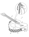
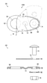
- FIG. 1 is a view showing an example of a strap pin 20 attached to a musical instrument 12.
- an instrument strap hereinafter simply referred to as a "strap" 30 is used. Therefore, the strap pin 20 for attaching the strap 30 is attached to the musical instrument 12.
- the strap 30 is provided with a strip-shaped member 32 which can be adjusted in length, and tongue-shaped mounting portions 34 provided at both ends of the strip-shaped member 32.
- a mounting hole 36 (see FIG. 3) described later is formed in the mounting portion 34, and the strap pin 20 is detachably mounted.
- the strap pins 20 are respectively provided at the end portion 14 of the body 13 of the musical instrument 12 and the heel portion 16 at the junction with the neck 15 on the opposite side of the end portion 14 of the body 13 of the musical instrument 12.
- the structure attached to is shown as an example, it is not limited to this structure.
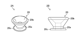
- FIG. 2 is a view showing an example of the strap pin 20.
- reference numeral 2 ⁇ / b> A shows a perspective view of the strap pin 20
- reference numeral 2 ⁇ / b> B shows a side view of the strap pin 20.
- the strap pin 20 spreads outward (in the radial direction orthogonal to the axial direction of the narrowed portion 20a) at the narrowed portion 20a having a circular cross section and the tip of the narrowed portion 20a.
- An enlarged diameter portion 20b having a square shape and an attachment portion (attachment plate) 20c provided on the opposite side of the enlarged diameter portion 20b of the constricted portion 20a and constituting an attachment surface with the musical instrument 12 are provided.
- the strap pins 20 are fixed to the musical instrument 12 by screws (not shown).
- the strap pin 20 may be of various shapes and sizes, but its overall features are substantially the same as those shown in FIG.
- FIG. 3 is a view showing an example of the mounting portion 34 of the strap 30.
- the mounting portion 34 of the strap 30 is provided with a mounting hole 36 for mounting the strap pin 20.
- a slit 38 is formed in connection with the mounting hole 36.
- the mounting hole 36 is expanded by the slit 38, and the enlarged diameter portion 20 b of the strap pin 20 is penetrated through the mounting hole 36 to position the constricted portion 20 a in the mounting hole 36.
- the slit 38 is fixed by narrowing at the constricted portion 20a and fixed by the enlarged diameter portion 20b so that the attached state of the strap 30 to the musical instrument 12 can be maintained.
- the player can use the strap 30 attached to the musical instrument 12 by suspending it with his shoulder when playing while standing.
- Patent Document 1 the reinforcing portion is superimposed on the strap mounting portion, and the strap mounting portion and the reinforcing portion at different positions where slits from the mounting hole (holding hole) are overlapped are mounted on the strap pin. Straps are disclosed.
- the strap disclosed in Patent Document 1 has a structure in which the strap can not be easily detached from the strap pin of the musical instrument as compared to the conventional strap (see FIG. 3), the strap is obtained by adopting this structure. It is difficult for the player to remove, and it is not convenient for the player. In addition, if the strap is repeatedly attached and removed, the attachment hole of the strap is necessarily slackened, the holding power of the instrument is weakened, and the instrument may be dropped.
- the present invention has been made in view of such circumstances, and an object thereof is to provide a strap pin fitting capable of easily attaching and detaching a strap to an instrument.
- a strap pin fitting includes a base plate, a strap holding portion disposed on the base plate for holding the strap, a through hole formed in the base plate and into which the strap pin can be inserted, and the base A holding plate attached to the plate, wherein the through hole is opened to allow insertion of the strap pin into the through hole, and a part of the through hole is closed to extract the strap pin from the through hole And a presser plate movable between a closed position that prevents movement.
- the presser plate is rotatably mounted about a direction orthogonal to the normal direction of the base plate.
- the presser plate is rotatably mounted centering on the normal direction of the base plate.
- a strap pin fitting according to a fourth aspect of the present invention comprises a biasing member for biasing the presser plate to the closed position in the second or third aspect.
- the through holes are formed by connecting a large hole portion and a small hole portion having mutually different hole diameters. Ru.
- the through hole is configured by one round hole.
- attachment and detachment of the strap to the musical instrument can be easily performed.
- FIG showing an example of strap pins attached to an instrument Figure showing an example of strap pin Figure showing an example of the strap attachment part The figure which showed the strap pin metal fitting which concerns on 1st Embodiment.
- the figure for demonstrating the connection method of the strap pin metal fitting and strap pin which concern on 1st Embodiment The figure for demonstrating the connection method of the strap pin metal fitting and strap pin which concern on 1st Embodiment.
- the figure which showed the strap pin metal fitting which is the development example of this invention The figure for demonstrating the connection method of the strap pin metal fitting and the strap pin which is the development example of this invention.
- the figure for demonstrating the connection method of the strap pin metal fitting and the strap pin which is the development example of this invention The figure for demonstrating the connection method of the strap pin metal fitting and the strap pin which is the development example of this invention.
- FIG. 4 is a view showing the strap pin fitting 50 according to the first embodiment.
- reference numeral 4A indicates a plan view of the strap pin fitting 50
- reference numeral 4B indicates a side view of the strap pin fitting 50.
- the strap pin fitting 50 of the present embodiment is a connecting tool which is interposed between the strap pin 20 and the strap 30 to connect them and mainly includes the base plate 52 and the pressing plate 54. , Strap holder 56.
- the base plate 52 is formed of a flat member.
- the base plate 52 is formed with a through hole 58 into which the strap pin 20 can be inserted.
- the through holes 58 are configured by connecting large holes 58 a and small holes 58 b having different hole diameters.
- the large hole portion 58a has a substantially circular shape in a plan view.
- the small hole portion 58b has a long hole shape extending from the large hole portion 58a in the opposite direction to the strap holding portion 56.
- the large hole portion 58a is formed larger than the outer diameter of the enlarged diameter portion 20b of the strap pin 20, and is large enough to allow the enlarged diameter portion 20b of the strap pin 20 to be inserted.
- the small hole portion 58 b is formed larger than the outer diameter of the narrowed portion 20 a of the strap pin 20 and smaller than the outer diameter of the enlarged diameter portion 20 b of the strap pin 20. It has a size that can be inserted.
- the pressing plate 54 has a shape in which the rear side (the strap holding portion 56 side) in the front-rear direction (longitudinal direction of the base plate 52) is bent. That is, when the base plate 52 is viewed from the side, as shown by the reference numeral 4B in FIG. 4, the presser plate 54 has a substantially "H” shaped (substantially "L” shaped) shape. doing.
- the presser plate 54 is configured such that a front end portion 62 on the front side and a rear end portion 64 on the rear side are connected via a bending portion 66 which is a boundary portion.
- the pressing plate 54 is attached to the base plate 52 so as to be rotatable about a direction perpendicular to the normal direction of the base plate 52 as a rotation center.
- the holding plate 54 is mounted on a bending line along a direction orthogonal to the longitudinal direction of the base plate 52 via the hinge portion 68, and can rotate about a direction along the bending line as a rotation center It is in the state.
- the hinge portion 68 is composed of a spring-loaded hinge (corresponding to the “biasing member” of the present invention), and is biased in such a direction that the front end portion 62 of the pressing plate 54 is pressed against the base plate 52 by the biasing force of the spring. It is powered. That is, the front end portion 62 of the pressing plate 54 is urged by the spring of the hinge portion 68 to a closing position where the large hole portion 58a which is a part of the through hole 58 is closed.
- the strap holder 56 is formed of a cylindrical member disposed on the base plate 52.
- the strap holding portion 56 is formed in a size that can be inserted into the attachment hole 36 of the mounting portion 34 of the strap 30.
- the strap 30 is fixed to the strap holding portion 56 by inserting the strap holding portion 56 into the attachment hole 36 of the mounting portion 34 of the strap 30 and tightening and fixing with a screw (not shown).
- the mounting portion 34 of is connected.
- a cap may be fitted and connected to the tip of the strap holding portion 56, or the strap holding portion 56 and the mounting portion 34 of the strap 30 may be connected by a cord or the like.
- the strap holding portion 56 and the mounting portion 34 of the strap 30 may be connected using a pin, an E-ring or the like.
- the strap holding portion 56 is inserted through the mounting hole 36 of the mounting portion 34 of the strap 30 and a screw (not shown) Tighten and fix with.
- the strap pins 20 and the large holes 58a of the through holes 58 aligned the strap pins 20 are inserted through the through holes 58 from the lower surface side of the base plate 52.
- the enlarged diameter portion 20 b of the strap pin 20 can be inserted into the large hole portion 58 a of the through hole 58.
- the pressing plate naturally returns to the closed position where the large hole portion 58a of the through hole 58 is closed by the biasing force. As a result, the strap pin 20 does not fall out of the through hole 58, and the strap pin 50 and the strap pin 20 are securely coupled.
- the rear end portion 64 of the pressing plate 54 is pushed from above onto the base plate 52 to close the large hole 58 a of the through hole 58. Since the front end 62 moves from the closed position to the open position, the strap pin 20 can be slid to the large hole 58a to easily remove the strap pin 20 from the large hole 58a.
- the strap pin bracket 50 of the present embodiment is provided on the base plate 52 and the base plate 52, is formed on the strap holding portion 56 for holding the strap 30, and is formed on the base plate 52. And a holding plate 54 attached to the base plate 52.
- the holding plate 54 opens the through hole 58 to allow insertion of the strap pin 20 into the through hole 58. And the closed position for closing the part of the through hole 58 and blocking the withdrawal operation of the strap pin 20 from the through hole 58, the strap pin 50 and the strap pin 20 Coupling and decoupling can be performed easily and quickly.
- the strap 30 can be easily attached to and removed from the musical instrument 12 by connecting the strap 30 and the strap pin 20 with the strap pin fitting 50 interposed therebetween.
- the pressing plate 54 is biased to the closed position where the through hole 58 is closed by the biasing member (spring of the hinge portion 68).
- the present invention is not limited to this. Between a locked state in which the pressing plate 54 is fixed in the closed position and a non-locked state in which the pressing plate 54 is movable between the closed position and the open position using a locking mechanism (engagement mechanism) not shown. It may be switched.
- the configuration in which the base plate 52 is a flat plate member is shown as an example, but the present invention is not limited thereto.
- the base plate 52 is bent or curved in a mountain shape or valley shape along its longitudinal direction. It may be formed.
- the pressing plate 54 may be bent or curved in a mountain shape or a valley shape depending on the shape of the base plate 52. The same applies to a second embodiment and a development example described later.
- FIG. 7 is a view showing a strap pin fitting 50A according to the second embodiment.
- components common or similar to those in FIG. 4 are assigned the same reference numerals.
- the second embodiment is the same as the first embodiment except that the configuration of the pressing plate 54 is different.
- the holding plate 54 in the second embodiment functions as an elastically deformable leaf spring.
- the pressing plate 54 is rotatable about the normal direction of the base plate 52 as a rotation center.
- symbol 69 has shown the rotating shaft part of the base board 52. As shown in FIG.
- the strap pin bracket 50A and the strap pin 20 are connected, the strap pin 20 and the large hole 58a of the through hole 58 are aligned as in the first embodiment described above.
- the strap pin 20 is inserted into the large hole portion 58 a of the through hole 58 from the lower surface side of the base plate 52.
- the pressing plate 54 functioning as a plate spring is curved and deformed by its elastic force. Meanwhile, the strap pin 20 can be inserted into the large hole portion 58 a of the through hole 58.
- the pressing plate 54 naturally becomes its original shape by its elastic force. Returning to the closed position where the large hole portion 58a of the through hole 58 is closed. As a result, the strap pin 20 does not fall out of the through hole 58, and the strap pin fitting 50A and the strap pin 20 are securely coupled.
- the pressing plate 54 When releasing the connection between the strap pin 20 and the strap pin bracket 50A, as shown by reference numeral 7A in FIG. 7, the pressing plate 54 is at an open position where the large hole portion 58a of the through hole 58 is opened The strap pin 20 can be removed from the through hole 58 by rotating it to the illustrated position).
- the musical instrument 12 is configured by connecting the strap 30 and the strap pin 20 with the strap pin bracket 50A interposed as in the first embodiment.
- the attachment and removal of the strap 30 can be easily performed.
- the pressing plate 54 has a function of closing the large hole portion 58a which is a part of the through hole 58 so as to prevent the strap pin 20 from coming off, the strength to support the musical instrument 12 is not necessary. It is also possible to cope with a thin plate member made of resin or metal thinner than the presser plate 54 of the first embodiment.
- the pressing plate 54 is configured to be rotatable around the rotation shaft portion 69, but the pressing plate 54 is a large hole portion of the through hole 58 by a biasing member (spring or the like) not shown. It is desirable to be biased in the closed position closing the 58a. Thereby, it is possible to prevent the connection between the strap pin 50A and the strap pin 20 from being released carelessly.
- a biasing member spring or the like
- the pressing plate 54 be provided with an operating portion such as a projection.
- the pressing plate 54 can be easily rotated, and the removal operation can be easily performed.
- the through holes 58 provided in the base plate 52 are configured such that the large holes 58 a and the small holes 58 b having different hole diameters are connected, but the shape of the through holes 58 is not necessarily Even if it is not a combination of large and small holes, it is possible to fulfill the purpose of the present invention.
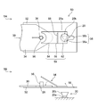
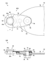
- FIG. 8 is a view showing a strap pin fitting 50B as a development example of the present invention.
- reference numeral 8A shows a plan view of the strap pin bracket 50B
- reference numeral 8B shows an exploded view of the strap pin bracket 50B.
- the same or similar components as or to those in FIG. 4 are denoted by the same reference numerals.
- the strap pin fitting 50B as a development example of the present invention has a generally rounded shape (substantially oval shape) from the viewpoint of design.
- the strap pin fitting 50B includes the base plate 52, the pressing plate 54, and the strap holding portion 56 in common with the above embodiments, but the shape of the through hole 58 formed in the base plate 52 Is a point that is constituted by a round hole in a plan view circular shape, a point that is greatly different from the above-described embodiments.
- the inner diameter of the through hole 58 is larger than the outer diameter of the enlarged diameter portion 20b of the strap pin 20 (see FIGS. 9 and 10).
- the pressing plate 54 has a shape substantially overlapping the base end side region (the region on the strap holding portion 56 side) of the base plate 52 when viewed in a plan view, as shown by reference numeral 8A in FIG. It is possible to rotate around the normal direction of 52 as the center of rotation.
- the pressing plate 54 is configured to close a part of the through hole 58 when disposed at a position (closing position) overlapping the base plate 52.
- the gap H formed between the through hole 58 and the pressing plate 54 is smaller than the outer diameter of the enlarged diameter portion 20 b of the strap pin 20 and larger than the outer diameter of the narrowed portion 20 a of the strap pin 20.
- the positional relationship and the size between the presser plate 54 and the through hole 58 are determined in such a manner as to become (see FIGS. 9 and 10).
- Recesses (recesses) 70 are provided on both sides (side surfaces) of the base plate 52, respectively. A non-overlapping region which does not overlap the base plate 52 is formed in the pressing plate 54 by the recessed portion 70, so that the pressing operation of the pressing plate 54 can be performed by pressing the pressing plate 54 corresponding to this region in the rotation direction. It becomes possible to carry out simply.
- a convex portion 72 having a circular shape in a plan view and protruding toward the side opposite to the pressing plate 54 is formed on the base plate 52 in an intermediate region corresponding to between the strap holding portion 56 and the through hole 58. There is.
- the convex portion 72 functions as a strap support portion that supports the tip end portion of the strap 30 when the strap 30 is attached to the strap pin fitting 50B.
- the strap holding portion 56 is a portion for fixing the strap 30 to the base plate 52 using the bolt 74 and the nut 76.
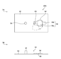
- the strap 30 When attaching the strap 30 to the strap holding portion 56, as shown in 9A and 9B of FIG. 9, it is provided on the proximal end side of the base plate 52 and the rotation hole 78 provided on the proximal end side of the pressing plate 54.
- the bolt insertion holes 80 and the mounting holes 36 of the straps 30 aligned so as to overlap each other in plan view, the bolts 74 are inserted through the holes from the side of the pressing plate 54 and project from the opposite side
- the tip end of the bolt 74 is tightened and fixed by a nut 76 via a washer 82.
- the nut 76 is tightened to such an extent that the pressing plate 54 can rotate with the rotation hole 78 as a fulcrum.
- the strap pin fitting 50B and the strap 30 are connected, and the pressing plate 54 can be rotated.
- the pressing plate 54 When connecting the strap pin bracket 50B and the strap pin 20, as shown by reference numerals 9A and 9B in FIG. 9, the pressing plate 54 is operated to rotate in a predetermined direction (for example, clockwise direction) to hold the pressing plate 54. Move to the open position. Then, the strap pin 20 is inserted into the through hole 58 of the base plate 52. Next, as shown by reference numerals 10A and 10B in FIG. 10, the pressing plate 54 is rotated in the reverse direction (for example, counterclockwise direction), and the pressing plate 54 is in the original state, that is, the pressing plate 54 is in the closed position. Move it.
- a predetermined direction for example, clockwise direction
- the narrow portion 20a of the strap pin 20 inserted into the through hole 58 of the base plate 52 is disposed in the gap H formed between the through hole 58 and the pressing plate 54, so that the strap pin 20 does not fall out of the through hole 58, and the strap pin fitting 50B and the strap pin 20 are securely coupled.
- the through hole 58 provided in the base plate 52 is configured by one hole portion, and the pressing plate 54 is rotated. 54 can be configured to be switchable between a closed position where the through hole 58 is partially closed and an open position where the through hole 58 is opened. Therefore, attachment and detachment of the strap 30 to the musical instrument 12 can be easily performed by connecting the strap 30 and the strap pin 20 with the strap pin fitting 50B interposed therebetween, and the above-described embodiments. The same effect can be obtained.
- the pressing plate 54 is configured to be switchable between the closing position for closing a part of the through hole 58 and the opening position for opening the through hole 58 by the rotation operation of the pressing plate 54.
- the present invention is not limited to this configuration.
- the presser plate 54 may be formed of a thin resin or metal thin plate member and the presser plate 54 may function as an elastically deformable leaf spring. . According to this configuration, it is possible to connect the strap pin fitting 50B and the strap pin 20 in the same manner as in the second embodiment described above without rotating the pressing plate 54.
- the strap pins 20 are inserted into the through holes 58 from the lower surface side of the base plate 52.
- the pressing plate 54 functioning as a leaf spring bends and deforms the strap pin 20 while being bent and deformed. It can be inserted into the through hole 58.
- the presser plate When the narrow portion 20a of the strap pin 20 is slid to the edge of the through hole 58 (the edge opposite to the strap holding portion 56) after being inserted to the narrow portion 20a of the strap pin 20, the presser plate The spring 54 naturally returns to its original shape due to its elastic force, and returns to the closed position where the through hole 58 is partially closed. As a result, the strap pin 20 does not fall out of the through hole 58, and the strap pin fitting 50B and the strap pin 20 are securely coupled.
- the strap pin 20 can be removed from the through hole 58 by rotating the presser plate 54 as in the above-described embodiment. It becomes.
- the through-hole 58 provided in the base plate 52 is comprised by the round hole of planar view circular shape was shown as an example of a preferable aspect in the development mentioned above, it does not restrict to this, for example, elliptical shape It may be polygonal, or any other shape.
Landscapes
- Engineering & Computer Science (AREA)
- General Engineering & Computer Science (AREA)
- Physics & Mathematics (AREA)
- Acoustics & Sound (AREA)
- Multimedia (AREA)
- Mechanical Engineering (AREA)
- Auxiliary Devices For Music (AREA)
- Purses, Travelling Bags, Baskets, Or Suitcases (AREA)
- Snaps, Bayonet Connections, Set Pins, And Snap Rings (AREA)
- Stringed Musical Instruments (AREA)
Priority Applications (3)
| Application Number | Priority Date | Filing Date | Title |
|---|---|---|---|
| EP18873621.9A EP3690261A4 (en) | 2017-10-31 | 2018-10-29 | BELT PIN FITTING |
| CN201880070569.1A CN111295526A (zh) | 2017-10-31 | 2018-10-29 | 背带钉金属配件 |
| US16/860,600 US10971120B2 (en) | 2017-10-31 | 2020-04-28 | Strap pin fitting |
Applications Claiming Priority (2)
| Application Number | Priority Date | Filing Date | Title |
|---|---|---|---|
| JP2017-211053 | 2017-10-31 | ||
| JP2017211053A JP6750828B2 (ja) | 2017-10-31 | 2017-10-31 | ストラップピン金具 |
Related Child Applications (1)
| Application Number | Title | Priority Date | Filing Date |
|---|---|---|---|
| US16/860,600 Continuation US10971120B2 (en) | 2017-10-31 | 2020-04-28 | Strap pin fitting |
Publications (1)
| Publication Number | Publication Date |
|---|---|
| WO2019088018A1 true WO2019088018A1 (ja) | 2019-05-09 |
Family
ID=66331807
Family Applications (1)
| Application Number | Title | Priority Date | Filing Date |
|---|---|---|---|
| PCT/JP2018/040093 Ceased WO2019088018A1 (ja) | 2017-10-31 | 2018-10-29 | ストラップピン金具 |
Country Status (5)
| Country | Link |
|---|---|
| US (1) | US10971120B2 (enExample) |
| EP (1) | EP3690261A4 (enExample) |
| JP (1) | JP6750828B2 (enExample) |
| CN (1) | CN111295526A (enExample) |
| WO (1) | WO2019088018A1 (enExample) |
Cited By (1)
| Publication number | Priority date | Publication date | Assignee | Title |
|---|---|---|---|---|
| USD952734S1 (en) * | 2019-03-21 | 2022-05-24 | Bmg Works, Llc | Guitar strap with tortoiseshell tri-glide adjuster |
Families Citing this family (4)
| Publication number | Priority date | Publication date | Assignee | Title |
|---|---|---|---|---|
| JP6750828B2 (ja) * | 2017-10-31 | 2020-09-02 | 後藤ガット有限会社 | ストラップピン金具 |
| US11540649B2 (en) * | 2020-04-14 | 2023-01-03 | Dorel Juvenile Group, Inc. | Carry handle anchor system |
| JP7276693B2 (ja) * | 2020-09-09 | 2023-05-18 | カシオ計算機株式会社 | 鍵盤楽器 |
| US12272340B2 (en) * | 2022-03-16 | 2025-04-08 | Mark Ranalli | Guitar strap locking system |
Citations (6)
| Publication number | Priority date | Publication date | Assignee | Title |
|---|---|---|---|---|
| US828573A (en) * | 1905-12-18 | 1906-08-14 | I B Kleinert Rubber Co | Garment-hanger. |
| JPS63157324U (enExample) * | 1987-04-02 | 1988-10-14 | ||
| JPH09140439A (ja) * | 1995-11-17 | 1997-06-03 | Asahi Optical Co Ltd | ストラップ用吊り金具 |
| JP2004183739A (ja) * | 2002-12-02 | 2004-07-02 | Masatoshi Yasunori | 取付具 |
| JP2013217991A (ja) | 2012-04-05 | 2013-10-24 | Takashi Kunii | 楽器用ストラップ |
| US20170206871A1 (en) * | 2016-01-15 | 2017-07-20 | D'addario & Company, Inc. | Locking Strap Mechanism |
Family Cites Families (24)
| Publication number | Priority date | Publication date | Assignee | Title |
|---|---|---|---|---|
| US808573A (en) * | 1905-03-21 | 1905-12-26 | James S Patten | Journal-box. |
| JPS3523275Y1 (enExample) * | 1958-10-28 | 1960-09-14 | Yashica | |
| US3512226A (en) * | 1968-03-12 | 1970-05-19 | Textron Inc | Plastic hook and eye |
| JPS5217597Y2 (enExample) * | 1973-03-16 | 1977-04-20 | ||
| JPS5083460U (enExample) * | 1973-11-09 | 1975-07-17 | ||
| US4144794A (en) * | 1978-06-09 | 1979-03-20 | Silverman Allen B | Device for and method of removably securing a harness to a musical instrument |
| US4993127A (en) * | 1989-09-29 | 1991-02-19 | Standtastic | Locking attachment for guitar straps and the like |
| JP2780080B2 (ja) * | 1995-06-21 | 1998-07-23 | 後藤ガット有限会社 | ハーネスと弦楽器との連結装置 |
| DE19839372B4 (de) * | 1997-08-28 | 2004-04-15 | Fa. Gerhard Dimbath | Lösbare Gurtbefestigung an tragbaren Musikinstrumenten |
| US6032339A (en) * | 1999-03-03 | 2000-03-07 | Innovative Automation, Inc. | Locking fastener for a strap |
| US6259009B1 (en) * | 1999-07-29 | 2001-07-10 | Bolopick | Strap locking and pick storage device |
| CN100364830C (zh) * | 2002-11-21 | 2008-01-30 | 阿普丽佳葛西株式会社 | 育儿用具 |
| US7562422B2 (en) * | 2004-06-28 | 2009-07-21 | Innovative Automation, Inc. | Locking fastener for a strap |
| US20060081112A1 (en) * | 2004-10-18 | 2006-04-20 | Gipson Howard K | Device(s) for and method(s) of adapting and retaining straps |
| US7256337B1 (en) * | 2005-12-30 | 2007-08-14 | Timothy John Walker | Combination guitar pick and shoulder strap lock |
| US7888572B2 (en) * | 2007-01-05 | 2011-02-15 | Gibson Guitar Corp. | Guitar strap lock |
| US7818851B2 (en) * | 2007-07-25 | 2010-10-26 | Chris Perrotta | Strap lock |
| US20110136359A1 (en) * | 2009-12-09 | 2011-06-09 | Ronald Derrick Gregg | Guitar end pin jack plug |
| USD637942S1 (en) * | 2010-08-20 | 2011-05-17 | Ossur Hf | Strap retainer |
| US8920092B2 (en) * | 2011-04-18 | 2014-12-30 | D'addario & Company, Inc. | Rotatable end pin for instrument strap |
| US9589547B2 (en) * | 2014-07-25 | 2017-03-07 | Hogjim, LLC | Releasably securable end piece |
| US9947303B1 (en) * | 2016-02-12 | 2018-04-17 | Michael H. Dulin | Adapter device for attaching a strap to a musical instrument provided with a strap button |
| CN106952635B (zh) * | 2017-05-22 | 2023-08-25 | 东莞市华锦礼品有限公司 | 便携式自锁吉他带头及其自锁方法 |
| JP6750828B2 (ja) * | 2017-10-31 | 2020-09-02 | 後藤ガット有限会社 | ストラップピン金具 |
-
2017
- 2017-10-31 JP JP2017211053A patent/JP6750828B2/ja not_active Expired - Fee Related
-
2018
- 2018-10-29 WO PCT/JP2018/040093 patent/WO2019088018A1/ja not_active Ceased
- 2018-10-29 CN CN201880070569.1A patent/CN111295526A/zh active Pending
- 2018-10-29 EP EP18873621.9A patent/EP3690261A4/en not_active Withdrawn
-
2020
- 2020-04-28 US US16/860,600 patent/US10971120B2/en not_active Expired - Fee Related
Patent Citations (6)
| Publication number | Priority date | Publication date | Assignee | Title |
|---|---|---|---|---|
| US828573A (en) * | 1905-12-18 | 1906-08-14 | I B Kleinert Rubber Co | Garment-hanger. |
| JPS63157324U (enExample) * | 1987-04-02 | 1988-10-14 | ||
| JPH09140439A (ja) * | 1995-11-17 | 1997-06-03 | Asahi Optical Co Ltd | ストラップ用吊り金具 |
| JP2004183739A (ja) * | 2002-12-02 | 2004-07-02 | Masatoshi Yasunori | 取付具 |
| JP2013217991A (ja) | 2012-04-05 | 2013-10-24 | Takashi Kunii | 楽器用ストラップ |
| US20170206871A1 (en) * | 2016-01-15 | 2017-07-20 | D'addario & Company, Inc. | Locking Strap Mechanism |
Non-Patent Citations (1)
| Title |
|---|
| See also references of EP3690261A4 * |
Cited By (1)
| Publication number | Priority date | Publication date | Assignee | Title |
|---|---|---|---|---|
| USD952734S1 (en) * | 2019-03-21 | 2022-05-24 | Bmg Works, Llc | Guitar strap with tortoiseshell tri-glide adjuster |
Also Published As
| Publication number | Publication date |
|---|---|
| EP3690261A1 (en) | 2020-08-05 |
| CN111295526A (zh) | 2020-06-16 |
| US20200258486A1 (en) | 2020-08-13 |
| US10971120B2 (en) | 2021-04-06 |
| JP6750828B2 (ja) | 2020-09-02 |
| JP2019082635A (ja) | 2019-05-30 |
| EP3690261A4 (en) | 2020-11-25 |
Similar Documents
| Publication | Publication Date | Title |
|---|---|---|
| WO2019088018A1 (ja) | ストラップピン金具 | |
| JP4832552B2 (ja) | シンバルホルダ及びシンバルスタンド | |
| JP4557561B2 (ja) | ドアヒンジ、および取外し可能ドアチェック装置 | |
| CN104571380A (zh) | 锁固机构及箱型设备 | |
| CN101896677B (zh) | 用于将杆式锁的锁闭杆铰接到杆式锁的操作柄上的转接器 | |
| JP2017110759A (ja) | クランプ装置、クランプセット | |
| CN116095542A (zh) | 支架的腿打开角度变更构件及支架 | |
| KR100802130B1 (ko) | 커팅인써트의 장착 및 분리를 위한 키 | |
| TW458910B (en) | Pull with pivoting tie-down hoop | |
| JP6467984B2 (ja) | リベット | |
| JPH10205522A (ja) | 開閉体用のヒンジ装置 | |
| JP5335606B2 (ja) | バネ回動装置 | |
| JP5170738B2 (ja) | 電気機器収納用箱の蝶番構造 | |
| JP2003307068A (ja) | 開閉物の支持機構 | |
| KR101654783B1 (ko) | 문개폐용 핸들의 잠금구 고정장치 | |
| JP3143945U (ja) | 幟竿 | |
| KR20060025062A (ko) | 글로브박스의 스토퍼 | |
| JP3154741U (ja) | バネ回動装置 | |
| WO2006137313A1 (ja) | 保持装置 | |
| JP2006337669A (ja) | 光ファイバの保護カバー | |
| JP5469560B2 (ja) | 筆記具のクリップ構造 | |
| JP3165550U (ja) | マネキンの手首連結構造 | |
| JP7416610B2 (ja) | パネルファスナー | |
| JP2019150019A (ja) | ハンドルの反対側に備えられたパーム側第1サイドカバー開閉用ロックレバーを備える釣り用リール | |
| JP2010021923A (ja) | 導波管接続構造 |
Legal Events
| Date | Code | Title | Description |
|---|---|---|---|
| 121 | Ep: the epo has been informed by wipo that ep was designated in this application |
Ref document number: 18873621 Country of ref document: EP Kind code of ref document: A1 |
|
| NENP | Non-entry into the national phase |
Ref country code: DE |
|
| ENP | Entry into the national phase |
Ref document number: 2018873621 Country of ref document: EP Effective date: 20200430 |