WO2019087935A1 - 電動機およびターボ圧縮機 - Google Patents
電動機およびターボ圧縮機 Download PDFInfo
- Publication number
- WO2019087935A1 WO2019087935A1 PCT/JP2018/039722 JP2018039722W WO2019087935A1 WO 2019087935 A1 WO2019087935 A1 WO 2019087935A1 JP 2018039722 W JP2018039722 W JP 2018039722W WO 2019087935 A1 WO2019087935 A1 WO 2019087935A1
- Authority
- WO
- WIPO (PCT)
- Prior art keywords
- wire
- drive
- cross
- sectional area
- support
- Prior art date
Links
Images


Classifications
-
- H—ELECTRICITY
- H02—GENERATION; CONVERSION OR DISTRIBUTION OF ELECTRIC POWER
- H02K—DYNAMO-ELECTRIC MACHINES
- H02K16/00—Machines with more than one rotor or stator
-
- F—MECHANICAL ENGINEERING; LIGHTING; HEATING; WEAPONS; BLASTING
- F02—COMBUSTION ENGINES; HOT-GAS OR COMBUSTION-PRODUCT ENGINE PLANTS
- F02B—INTERNAL-COMBUSTION PISTON ENGINES; COMBUSTION ENGINES IN GENERAL
- F02B39/00—Component parts, details, or accessories relating to, driven charging or scavenging pumps, not provided for in groups F02B33/00 - F02B37/00
- F02B39/02—Drives of pumps; Varying pump drive gear ratio
- F02B39/08—Non-mechanical drives, e.g. fluid drives having variable gear ratio
- F02B39/10—Non-mechanical drives, e.g. fluid drives having variable gear ratio electric
-
- F—MECHANICAL ENGINEERING; LIGHTING; HEATING; WEAPONS; BLASTING
- F16—ENGINEERING ELEMENTS AND UNITS; GENERAL MEASURES FOR PRODUCING AND MAINTAINING EFFECTIVE FUNCTIONING OF MACHINES OR INSTALLATIONS; THERMAL INSULATION IN GENERAL
- F16C—SHAFTS; FLEXIBLE SHAFTS; ELEMENTS OR CRANKSHAFT MECHANISMS; ROTARY BODIES OTHER THAN GEARING ELEMENTS; BEARINGS
- F16C32/00—Bearings not otherwise provided for
- F16C32/04—Bearings not otherwise provided for using magnetic or electric supporting means
- F16C32/0406—Magnetic bearings
-
- H—ELECTRICITY
- H02—GENERATION; CONVERSION OR DISTRIBUTION OF ELECTRIC POWER
- H02K—DYNAMO-ELECTRIC MACHINES
- H02K3/00—Details of windings
- H02K3/04—Windings characterised by the conductor shape, form or construction, e.g. with bar conductors
- H02K3/12—Windings characterised by the conductor shape, form or construction, e.g. with bar conductors arranged in slots
-
- H—ELECTRICITY
- H02—GENERATION; CONVERSION OR DISTRIBUTION OF ELECTRIC POWER
- H02K—DYNAMO-ELECTRIC MACHINES
- H02K3/00—Details of windings
- H02K3/04—Windings characterised by the conductor shape, form or construction, e.g. with bar conductors
- H02K3/28—Layout of windings or of connections between windings
-
- H—ELECTRICITY
- H02—GENERATION; CONVERSION OR DISTRIBUTION OF ELECTRIC POWER
- H02K—DYNAMO-ELECTRIC MACHINES
- H02K7/00—Arrangements for handling mechanical energy structurally associated with dynamo-electric machines, e.g. structural association with mechanical driving motors or auxiliary dynamo-electric machines
- H02K7/08—Structural association with bearings
- H02K7/09—Structural association with bearings with magnetic bearings
-
- H—ELECTRICITY
- H02—GENERATION; CONVERSION OR DISTRIBUTION OF ELECTRIC POWER
- H02K—DYNAMO-ELECTRIC MACHINES
- H02K7/00—Arrangements for handling mechanical energy structurally associated with dynamo-electric machines, e.g. structural association with mechanical driving motors or auxiliary dynamo-electric machines
- H02K7/14—Structural association with mechanical loads, e.g. with hand-held machine tools or fans
-
- F—MECHANICAL ENGINEERING; LIGHTING; HEATING; WEAPONS; BLASTING
- F05—INDEXING SCHEMES RELATING TO ENGINES OR PUMPS IN VARIOUS SUBCLASSES OF CLASSES F01-F04
- F05D—INDEXING SCHEME FOR ASPECTS RELATING TO NON-POSITIVE-DISPLACEMENT MACHINES OR ENGINES, GAS-TURBINES OR JET-PROPULSION PLANTS
- F05D2220/00—Application
- F05D2220/40—Application in turbochargers
-
- F—MECHANICAL ENGINEERING; LIGHTING; HEATING; WEAPONS; BLASTING
- F05—INDEXING SCHEMES RELATING TO ENGINES OR PUMPS IN VARIOUS SUBCLASSES OF CLASSES F01-F04
- F05D—INDEXING SCHEME FOR ASPECTS RELATING TO NON-POSITIVE-DISPLACEMENT MACHINES OR ENGINES, GAS-TURBINES OR JET-PROPULSION PLANTS
- F05D2240/00—Components
- F05D2240/50—Bearings
- F05D2240/51—Magnetic
- F05D2240/511—Magnetic with permanent magnets
-
- H—ELECTRICITY
- H02—GENERATION; CONVERSION OR DISTRIBUTION OF ELECTRIC POWER
- H02K—DYNAMO-ELECTRIC MACHINES
- H02K1/00—Details of the magnetic circuit
- H02K1/06—Details of the magnetic circuit characterised by the shape, form or construction
- H02K1/22—Rotating parts of the magnetic circuit
- H02K1/27—Rotor cores with permanent magnets
- H02K1/2706—Inner rotors
- H02K1/272—Inner rotors the magnetisation axis of the magnets being perpendicular to the rotor axis
- H02K1/274—Inner rotors the magnetisation axis of the magnets being perpendicular to the rotor axis the rotor consisting of two or more circumferentially positioned magnets
- H02K1/2746—Inner rotors the magnetisation axis of the magnets being perpendicular to the rotor axis the rotor consisting of two or more circumferentially positioned magnets the rotor consisting of magnets arranged with the same polarity, e.g. consequent pole type
-
- H—ELECTRICITY
- H02—GENERATION; CONVERSION OR DISTRIBUTION OF ELECTRIC POWER
- H02K—DYNAMO-ELECTRIC MACHINES
- H02K2205/00—Specific aspects not provided for in the other groups of this subclass relating to casings, enclosures, supports
- H02K2205/03—Machines characterised by thrust bearings
-
- H—ELECTRICITY
- H02—GENERATION; CONVERSION OR DISTRIBUTION OF ELECTRIC POWER
- H02K—DYNAMO-ELECTRIC MACHINES
- H02K2213/00—Specific aspects, not otherwise provided for and not covered by codes H02K2201/00 - H02K2211/00
- H02K2213/03—Machines characterised by numerical values, ranges, mathematical expressions or similar information
-
- H—ELECTRICITY
- H02—GENERATION; CONVERSION OR DISTRIBUTION OF ELECTRIC POWER
- H02K—DYNAMO-ELECTRIC MACHINES
- H02K7/00—Arrangements for handling mechanical energy structurally associated with dynamo-electric machines, e.g. structural association with mechanical driving motors or auxiliary dynamo-electric machines
- H02K7/08—Structural association with bearings
- H02K7/083—Structural association with bearings radially supporting the rotary shaft at both ends of the rotor
Definitions
- the present disclosure relates to a motor and a turbo compressor.
- Patent Document 1 discloses a bearingless motor including a motor winding of a plurality of poles disposed in a stator, and a plurality of magnetic support windings disposed independently of the motor winding and different from the motor winding. Is described.
- a support electric wire forming a winding portion for generating an electromagnetic force (supporting force) for supporting the drive shaft in a noncontact manner and a drive wire for rotationally driving the drive shaft.
- a drive wire forming a winding portion for generating an electromagnetic force (drive force) is wired so as to pass through a plurality of slots respectively formed between a plurality of teeth.
- a common wire is used to form a support wire and a drive wire, and the space factor required for each of the support wire and the drive wire (pass the slot to the cross sectional area of the slot) It is conceivable to adjust the number of the leads forming the support wire and the number of the leads forming the drive wire according to the ratio of the total cross-sectional area of the leads).
- this indication aims at providing the electric motor which can improve the design freedom of an electric wire, securing the space factor required for an electric wire.
- a first aspect of the disclosure relates to a motor, which comprises a rotor (30) and a stator (40).
- the stator (40) includes a stator core (50) having a back yoke (51) formed in an annular shape, and a plurality of teeth (52) provided on the inner periphery of the back yoke (51).
- the rotor (30) is wired by passing through a plurality of slots (53) formed of one or more conducting wires (61) and formed between the plurality of teeth (52).
- a support wire (60) forming a winding portion for generating an electromagnetic force for supporting in a non-contact manner, and one or more conducting wires (71), and wiring passing through the plurality of slots (53)
- a drive wire (70) forming a winding portion for generating an electromagnetic force for rotationally driving the rotor (30) by energization, and a conductive wire (61) constituting the support wire (60).
- the cross-sectional area per one is equivalent to one conductor (71) that constitutes the drive wire (70). It is different from the Rinodan area.
- the cross-sectional area of the wire passing through the slot (53) with respect to the space factor of one of the support wire (60) and the drive wire (70) ie, the cross-sectional area of the slot (53)
- the allowable bending radius of the other of the support wire (60) and the drive wire (70) can be reduced while improving the ratio of the total of Thereby, the design freedom of the wire can be improved while securing the space factor required for the wire.
- a second aspect of the present disclosure relates to the first aspect, wherein the cross section of the slot (53) of the support wire (60) and the drive wire (70) passes through the slot (53).
- the cross-sectional area per wire constituting the wire in which the proportion of the total cross-sectional area of the wires is lower is equal to the cross-sectional area of the support wire (60) and the drive wire (70) of the slot (53).
- the ratio of the total cross-sectional area of the wires passing through the slot (53) is smaller than the cross-sectional area per wire constituting the wire having the higher ratio.
- the space factor in the slot (53) of the support wire (60) and the drive wire (70) ie, the wire passing through the slot (53) with respect to the cross-sectional area of the slot (53) It is possible to increase the space factor of the wire with the higher proportion of the total cross-sectional area). Thereby, the space factor of the electric wire in the slot (53) (the sum of the space factor of the support wire (60) and the space factor of the drive wire (70)) can be effectively improved.
- a third aspect of the present disclosure relates to the first aspect and constitutes an electric wire having a larger number of conductors passing through the slot (53) of the support electric wire (60) and the drive electric wire (70).
- the cross-sectional area per wire is the cross-sectional area per wire constituting the wire having the smaller number of wires passing through the slot (53) among the support wire (60) and the drive wire (70). It is smaller than that.
- the allowable bending of the wire having the larger number of wires passing through the slot (53) among the support wire (60) and the drive wire (70) (the wire in which the coil end tends to be large)
- the radius can be reduced.
- it is possible to easily miniaturize the coil end portion of the motor (the portion constituted by the coil end portion of the support wire (60) and the coil end portion of the drive wire (70)).
- a fourth aspect of the present disclosure relates to the first aspect and constitutes an electric wire of which the total of the cross-sectional areas of the conductive wire constituting the electric wire is smaller among the support electric wire (60) and the drive electric wire (70).
- the cross-sectional area per wire is the cross-sectional area per wire constituting the wire having the larger total of the cross-sectional areas of the supporting wire (60) and the drive wire (70) constituting the wire. It is smaller than that.
- the fourth aspect it is possible to increase the space factor of the larger one of the support wire (60) and the drive wire (70), which has a larger total cross-sectional area of the wires constituting the wire.
- the space factor of the electric wire in the slot (53) (the sum of the space factor of the support wire (60) and the space factor of the drive wire (70)) can be effectively improved.
- a fifth aspect of the present disclosure relates to the first aspect and constitutes an electric wire having a larger number of electric wires passing through the slot (53) of the support electric wire (60) and the drive electric wire (70).
- the cross-sectional area per wire is the cross-sectional area per wire constituting the wire having the smaller number of wires passing through the slots (53) among the support wire (60) and the drive wire (70). It is smaller than that.
- the allowable bending of the wire having the larger number of wires passing through the slot (53) among the support wire (60) and the drive wire (70) (the wire in which the coil end tends to be large)
- the radius can be reduced.
- it is possible to easily miniaturize the coil end portion of the motor (the portion constituted by the coil end portion of the support wire (60) and the coil end portion of the drive wire (70)).
- a sixth aspect of the present disclosure relates to any one of the first to fifth aspects, wherein the cross-sectional area per lead (61) constituting the support electric wire (60) is the drive electric wire (70). Smaller than the cross-sectional area per one of the conducting wires (71) constituting the
- the allowable bending radius of the support wire (60) can be reduced while effectively improving the space factor of the drive wire (70).
- the space factor of the drive wire (70) it is possible to increase the electromagnetic force (electromagnetic force for driving the rotor (30) to rotate) generated by energization of the drive wire (70).
- the torque of the rotor (30) it is possible to increase the torque of the rotor (30). Therefore, by effectively improving the space factor of the drive wire (70), it is possible to easily secure the electromagnetic force required to rotate the rotor (30).
- a seventh aspect of the present disclosure relates to any one of the first to sixth aspects, in which the cross-sectional area per one lead of the support wire (60) and the drive wire (70) is smaller. A part or all of the coil end of the wire is covered with the part or all of the coil end of the wire having a larger cross-sectional area per one of the support wire (60) and the drive wire (70). It is
- the coil end portion and the stator core of the wire having the larger cross-sectional area per wire among the support wire (60) and the drive wire (70) (the wire having the larger allowable bending radius)
- the dead space between (50) and the coil end portion of the wire having the smaller cross-sectional area per one of the support wire (60) and the drive wire (70) (the wire having the smaller allowable bending radius) Can be placed.
- the coil end portion of the motor the portion constituted by the coil end portion of the support wire (60) and the coil end portion of the drive wire (70)).
- An eighth aspect of the present disclosure relates to the seventh aspect, in which one of the support wire (60) and the drive wire (70), which has a larger cross-sectional area per one wire constituting the wire, It is comprised by the segment coil (80).
- the eighth aspect it is possible to facilitate attachment of the support wire (60) and the drive wire (70), which has a larger cross-sectional area per lead.
- a ninth aspect of the present disclosure relates to any one of the first to eighth aspects, wherein the support wire (60) and the drive wire (70) are adjacent in the circumferential direction of the stator (40). It is arranged to fit.
- a tenth aspect of the present disclosure relates to the ninth aspect, wherein the support wire (60) and the drive wire (70) constitute the wire among the support wire (60) and the drive wire (70).
- the wire having the smaller cross-sectional area per wire is larger in the cross-sectional area per wire constituting the wire among the support wire (60) and the drive wire (70).
- the wire with the larger cross-sectional area per lead is used.
- the smaller cross section per wire smaller allowable bending radius) Cable
- an eleventh aspect of the present disclosure relates to a turbo compressor, and the turbo compressor includes a motor according to any one of the first to tenth aspects, and a drive shaft (12) rotationally driven by the motor. And an impeller (13) connected to the drive shaft (12).
- the design freedom of the wire can be improved while securing the space factor required for the wire.
- FIG. 1 is a longitudinal cross-sectional view illustrating the configuration of a turbo compressor.
- FIG. 2 is a cross-sectional view illustrating the configuration of a bearingless motor.
- FIG. 3 is a cross-sectional view illustrating a magnet magnetic flux and a drive magnetic flux generated in a bearingless motor.
- FIG. 4 is a cross-sectional view illustrating magnet magnetic flux and support magnetic flux generated in a bearingless motor.
- FIG. 5 is a cross-sectional view illustrating magnet magnetic flux, drive magnetic flux, and support magnetic flux generated in a bearingless motor.
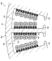
- FIG. 6 is a partial cross-sectional view illustrating the configuration of the stator.
- FIG. 7 is a partial cross-sectional view illustrating Modified example 1 of the stator.
- FIG. 1 is a longitudinal cross-sectional view illustrating the configuration of a turbo compressor.
- FIG. 2 is a cross-sectional view illustrating the configuration of a bearingless motor.
- FIG. 3 is a cross-sectional view
- FIG. 8 is a partial cross-sectional view illustrating Modified example 2 of the stator.
- FIG. 9 is a partial cross-sectional view illustrating Modified example 3 of the stator.
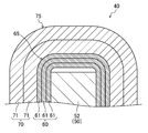
- FIG. 10 is a partial cross-sectional view illustrating Modified example 4 of the stator.
- FIG. 11 is a partial plan view illustrating a fifth modification of the stator.
- FIG. 12 is a partial plan view illustrating a modified example 6 of the stator.
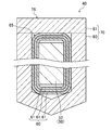
- FIG. 13 is a partial cross-sectional view illustrating modified example 6 of the stator.
- FIG. 1 illustrates the configuration of a turbo compressor (10) according to an embodiment.
- the turbo compressor (10) is provided in a refrigerant circuit (not shown) and configured to compress the refrigerant.
- the turbo compressor (10) comprises a casing (11), a drive shaft (12), an impeller (13), and one or more (two in this example) bearingless motors (20)
- axial direction refers to the rotational axis direction and refers to the axial center direction of the drive shaft (12)
- radial direction refers to the drive shaft (12)
- the casing (11) is formed in a cylindrical shape whose both ends are closed, and is disposed such that the cylinder axis is oriented horizontally.
- the space in the casing (11) is divided by the wall (11a), and the space on the right side of the wall (11a) constitutes an impeller chamber (S1) for housing the impeller (13), and the wall (11a)
- the space on the left side of the motor room constitutes a motor room (S2) in which the bearingless motor (20) is accommodated.
- a bearingless motor (20), a first touchdown bearing (14), a second touchdown bearing (15), and a thrust magnetic bearing (16) are accommodated. It is being fixed to the inner peripheral wall of S2).
- the drive shaft (12) is provided to rotationally drive the impeller (13).
- the drive shaft (12) extends axially in the casing (11) to connect the impeller (13) and the bearingless motor (20).
- the impeller (13) is fixed to one end of the drive shaft (12), and the bearingless motor (20) is disposed in the middle of the drive shaft (12).
- a disc-like portion (hereinafter referred to as "disc portion (12a)") is provided at the other end of the drive shaft (12) (that is, the end opposite to the end to which the impeller (13) is fixed).
- the drive shaft (12) is made of a magnetic material (for example, iron).
- the impeller (13) is formed to have a substantially conical outer shape by a plurality of blades, and is connected to the drive shaft (12).
- the impeller (13) is accommodated in the impeller chamber (S1) while being fixed to one end of the drive shaft (12).
- a suction pipe (P1) and a discharge pipe (P2) are connected to the impeller chamber (S1).
- the suction pipe (P1) is provided to guide the refrigerant (fluid) from the outside to the impeller chamber (S1).
- the discharge pipe (P2) is provided to return the high-pressure refrigerant (fluid) compressed in the impeller chamber (S1) to the outside. That is, in this example, the impeller (13) and the impeller chamber (S1) constitute a compression mechanism.
- the bearingless motor (20) has a rotor (30) and a stator (40), supports the drive shaft (12) in a noncontact manner by electromagnetic force, and rotationally drives the drive shaft (12) by electromagnetic force. It is configured to let you
- the rotor (30) is fixed to the drive shaft (12)
- the stator (40) is fixed to the inner peripheral wall of the casing (11).
- two bearingless motors (20) are arranged side by side in the axial direction of the drive shaft (12). The configuration of the bearingless motor (20) will be described in detail later.
- the first touch down bearing (14) is provided in the vicinity of one end (right end in FIG. 1) of the drive shaft (12), and the second touch down bearing (15) is the other end of the drive shaft (12) It is provided in the vicinity of (the left end in FIG. 1).
- the first and second touch down bearings (14, 15) support the drive shaft (12) when the bearingless motor (20) is de-energized (ie when the drive shaft (12) is not floating) Is configured as.
- the thrust magnetic bearing (16) has first and second thrust electromagnets (16a, 16b), and is configured to support the disc portion (12a) of the drive shaft (12) in a noncontact manner by an electromagnetic force.
- each of the first and second thrust electromagnets (16a, 16b) has a stator core formed in an annular shape and a winding portion (electric wire), and the disk portion of the drive shaft (12)
- the disc portion (12a) of the drive shaft (12) is supported in a contactless manner by the combined electromagnetic force of the first and second thrust electromagnets (16a, 16b).
- the combined electromagnetic force of the first and second thrust electromagnets (16a, 16b) is controlled to control the first and second thrust electromagnets. It is possible to control the position of the drive shaft (12) in the opposing direction (i.e., the axial direction, the left and right direction in FIG. 1) of (16a, 16b).
- Each part of the turbo compressor (10) is provided with various sensors (not shown) such as a position sensor, a current sensor, and a rotational speed sensor.
- the bearingless motor (20) is provided with a position sensor (not shown) for outputting a detection signal according to the position of the rotor (30) in the radial direction (radial direction), and the thrust magnetic bearing (16)
- the position sensor (not shown) for outputting a detection signal corresponding to the position of the drive shaft (12) in the thrust direction (axial direction).
- These position sensors are constituted by, for example, an eddy current displacement sensor that detects a gap (distance) to a measurement object.
- the controller (17) is a component of the turbo compressor (10) such that the rotational speed of the drive shaft (12) becomes a predetermined target rotational speed in a state where the drive shaft (12) is supported in a non-contact manner.
- the motor voltage command value and the thrust voltage command value are generated and output based on information such as detection signals from various sensors provided in and the target rotational speed of the drive shaft (12).
- the motor voltage command value is a command value for controlling the voltage supplied to the winding portion (electric wire) of the stator (40) of the bearingless motor (20).
- the thrust voltage command value is a command value for controlling the voltage supplied to the winding portion (electric wire) of the first and second thrust electromagnets (16a, 16b) of the thrust magnetic bearing (16).
- the control unit (17) includes, for example, an arithmetic processing unit such as a CPU, and a storage unit such as a program for operating the arithmetic processing unit and a memory for storing information.
- the power supply unit (18) and the winding unit (electric wire) of the stator (40) of the bearingless motor (20) are based on the motor voltage command value and the thrust voltage command value output from the control unit (17). Voltages are supplied to the winding portions (wires) of the first and second thrust electromagnets (16a, 16b) of the thrust magnetic bearing (16).
- the power supply unit (18) is configured of, for example, a PWM (Pulse Width Modulation) amplifier.
- the current flowing in the winding portion (electric wire) of the stator (40) is controlled to perform the bearing
- the magnetic flux generated in the brushless motor (20) can be controlled.
- the first and second thrust electromagnets (16a, 16b) are controlled by controlling the voltage supplied to the winding portions (wires) of the first and second thrust electromagnets (16a, 16b) of the thrust magnetic bearing (16).
- the current flowing through the winding portion (electric wire) of (1) can be controlled to control the combined electromagnetic force of the first and second thrust electromagnets (16a, 16b).
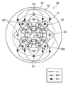
- FIG. 2 illustrates the configuration of the bearingless motor (20).
- the bearingless motor (20) constitutes a consistent pole type bearingless motor (embedded magnet type bearingless motor).
- the illustration of the winding portion (electric wire) is simplified, and the illustration of hatching is omitted.
- the rotor (30) has a rotor core (31) and a plurality of (four in this example) permanent magnets (32) provided on the rotor core (31).
- the rotor core (31) is made of a magnetic material (for example, laminated steel plates) and formed in a cylindrical shape.
- a shaft hole for inserting the drive shaft (12) is formed in the central portion of the rotor core (31).
- the plurality of permanent magnets (32) are arranged at a predetermined angular pitch in the circumferential direction of the rotor (30).
- four permanent magnets (32) are arranged at an angular pitch of 90 ° in the circumferential direction of the rotor (30).
- the four permanent magnets (32) are embedded in the vicinity (outer periphery) of the outer peripheral surface of the rotor core (31), and each has a shape (circle) along the outer peripheral surface of the rotor core (31) Arc shaped).
- the outer peripheral surface side of the four permanent magnets (32) is an N pole, and among the outer peripheral surfaces of the rotor core (31), between the four permanent magnets (32) in the circumferential direction of the rotor (30) The portion located is pseudo S-pole.
- the outer peripheral surface side of the four permanent magnets (32) may be the S pole.
- a portion of the outer peripheral surface of the rotor core (31) located between the four permanent magnets (32) in the circumferential direction of the rotor (30) virtually becomes an N pole.
- the stator (40) has a stator core (50), a support wire (60), and a drive wire (70).
- the stator core (50) is made of a magnetic material (for example, laminated steel plates), and has a back yoke (51) and a plurality of (24 in this example) teeth (52).
- the back yoke (51) is formed in an annular shape (in this example, an annular shape).
- the plurality of teeth (52) are provided on the inner periphery of the back yoke (51).
- the plurality of teeth (52) are arranged at predetermined intervals in the circumferential direction of the stator (40).
- a slot (53) through which the support wire (60) and the drive wire (70) pass is formed between two adjacent teeth (52) in the circumferential direction of the stator (40).
- a plurality of (24 in this example) slots (53) are respectively formed between a plurality of (24 in this example) teeth 52 arranged in the circumferential direction of the stator (40).
- the support wire (60) is constituted by one or more conducting wires (61).
- the conducting wire (61) is made of a conductive material such as copper.
- the support wire (60) is wired so as to pass through the plurality of slots (53) respectively formed between the plurality of teeth (52), and the support winding portion (the rotor (30) is not It forms the winding part which generates the electromagnetic force for supporting by contact.
- three-phase support wires (U-phase support wire (60u), V-phase support wire (60v) and W-phase support wire (60w)) are provided on the stator (40).
- the support wire (60) surrounded by the thin dashed-dotted line corresponds to the U-phase support wire (60u)
- the support wire (60) surrounded by the thin dashed line is the V-phase support wire (60v)
- the support wire (60) which corresponds and is surrounded by a thin dotted line corresponds to the W-phase support wire (60 w).
- the configuration of the support wire (60) will be described in detail later.
- the drive wire (70) is constituted by one or more conducting wires (71).
- the conducting wire (71) is made of a conductive material such as copper.
- the drive wire (70) is wired so as to pass through the plurality of slots (53) respectively formed between the plurality of teeth (52) to rotate the drive winding portion (the rotor (30) is rotated by energization).
- a winding portion for generating an electromagnetic force for driving is formed.
- three-phase drive wires (U-phase drive wire (70u), V-phase drive wire (70v) and W-phase drive wire (70w)) are provided on the stator (40).
- the drive wire (70) surrounded by the thin alternate long and short dash line corresponds to the U-phase drive wire (70u)
- the drive wire (70) surrounded by the thin broken line corresponds to the V-phase drive wire (70v)
- the corresponding drive wire (70) surrounded by a thin dotted line corresponds to the W-phase drive wire (70 w).
- the configuration of the drive wire (70) will be described in detail later.
- FIG. 3 shows a magnet flux (a magnet flux (.phi.1) generated by a permanent magnet (32)) generated in a bearingless motor (20) and a drive flux (a drive flux (BM1) produced to drive a drive shaft (12). And are illustrated.
- the drive magnetic flux (BM1) is a magnetic flux generated in response to the current flowing through the winding portion of the drive wire (70).
- the bearingless motor (20) rotates the drive shaft (12) by the interaction between the magnet magnetic flux (.phi.1) and the drive magnetic flux (BM1), thereby counteracting the drive shaft (12 in FIG. 3).
- the driving torque (T1) for rotating in the clockwise direction is generated.
- FIG. 3 shows a current (IM1) equivalent to the current flowing through the winding portion of the drive wire (70).
- FIG. 4 illustrates the magnet magnetic flux ( ⁇ 1) generated in the bearingless motor (20) and the supporting magnetic flux (supporting magnetic flux (BS1) generated to support the drive shaft (12) in a noncontact manner).
- the support magnetic flux (BS1) is a magnetic flux generated in response to the current flowing through the winding portion of the support wire (60).
- the bearingless motor (20) supports the drive shaft (12) in a non-contact manner by the interaction between the magnet magnetic flux ( ⁇ 1) and the support magnetic flux (BS1).
- the electromagnetic force (the drive shaft (12) in FIG. 4) To generate a supporting force (F1) acting in the right direction.
- a current (IS1) equivalent to the current flowing through the winding portion of the support wire (60) is shown.
- FIG. 5 illustrates the magnet magnetic flux ( ⁇ 1), the drive magnetic flux (BM1) and the support magnetic flux (BS1) generated in the bearingless motor (20).
- the bearingless motor (20) simultaneously generates the driving torque (T1) and the supporting force (F1) by the interaction of the magnet magnetic flux ( ⁇ 1), the driving magnetic flux (BM1) and the supporting magnetic flux (BS1). It is configured.
- FIG. 5 shows a current (IM1) equivalent to the current flowing in the winding portion of the drive wire (70) and a current (IS1) equivalent to the current flowing in the winding portion of the support wire (60). ing.
- the support wire (60) is composed of a plurality (9 in this example) of conductors (61)
- the drive wire (70) is composed of a plurality of (4 in this example) of conductors (71)
- a bundle of nine conducting wires (61) constituting one supporting wire (60) is surrounded by a dotted line
- a bundle of four conducting wires (71) constituting one driving wire (70) is a dotted line It is surrounded by.
- the support wire (60) and the drive wire (70) passing through one slot (53) are electrically isolated from each other.
- a member for electrically insulating the insulating member (the support wire (60) and the drive wire (70) between the support wire (60) passing through one slot (53) and the drive wire (70) , Not shown) is provided.
- the support wire (60) and the drive wire (70) are respectively wired between the plurality of teeth (52) by distributed winding. Further, the support wire (60) is disposed radially outward of the drive wire (70) in one slot (53).
- the cross-sectional area per one lead (61) that constitutes the support wire (60) is different from the cross-sectional area per one lead (71) that constitutes the drive wire (70).
- the cross-sectional area per lead (61) constituting the support wire (60) is smaller than the cross-sectional area per lead (71) constituting the drive wire (70).
- the space factor of the support wire (60) and the drive wire (70) in the slot (53) ie, the cross section of the slot (53) is cut off of the wire passing through the slot (53)
- the cross-sectional area per conductor forming the wire with the lower proportion of the total area is the higher of the space factor in the slot (53) of the support wire (60) and the drive wire (70). It is smaller than the cross-sectional area per one of the conductors constituting the electric wire.
- the space factor of the support wire (60) in the slot (53) is lower than the space factor of the drive wire (70) in the slot (53).
- the ratio of the total cross-sectional area of the conducting wire (61) of the support wire (60) passing through the slot (53) to the cross-sectional area of the slot (53) is the slot relative to the cross-sectional area of the slot (53)
- the ratio of the total cross-sectional area of the conducting wire (71) of the drive wire (70) passing through (53) is lower than the ratio.
- the space factor of the support wire (60) in the slot (53) is the conductor (61) of the support wire (60) passing through the slot (53) relative to the sectional area (opening area) of the slot (53) It corresponds to the ratio that the total of the cross-sectional area of And the total cross-sectional area of the conducting wire (61) of the supporting wire (60) passing through one slot (53) is the number of times the supporting wire (60) passes through one slot (53), and one supporting wire It corresponds to the product of the total of the cross-sectional areas of the conducting wire (61) constituting (60).
- the space factor of the drive wire (70) in the slot (53) is equal to the cross-sectional area (opening area) of the slot (53), the conductive wire of the drive wire (70) in the slot (53) It corresponds to the ratio that the total of the cross-sectional area of 71) occupies.
- the total cross-sectional area of the conducting wire (71) of the driving wire (70) in one slot (53) is the number of times the driving wire (70) passes through one slot (53) 70) corresponds to the product of the total of the cross-sectional areas of the conductors (71) that constitute 70).
- the number of conductors (61) of the support wire (60) passing through one slot (53) is greater than the number of conductors (71) of the drive wire (70) passing through one slot (53) It has increased.
- the number of conductors (61) of the support wire (60) passing through one slot (53) is the number of conductors (61) constituting one support wire (60) and the number of support wires (60) It corresponds to the product of the number of times of passing through one slot (53).
- the cross-sectional area per one conducting wire which constitutes the electric wire having the smaller total of the cross-sectional areas of the conducting wire constituting the electric wire among the supporting electric wire (60) and the driving electric wire (70) And the drive wire (70) is smaller than the cross-sectional area per one wire constituting the larger wire.
- the total of the cross-sectional areas of the conducting wires (61) constituting the support wire (60) is smaller than the total of the cross-sectional areas of the conducting wires (71) constituting the drive wire (70).
- the total of the cross-sectional areas of the nine conducting wires (61) constituting the support wire (60) is the cross-sectional area of the four conducting wires (71) constituting the drive wire (70). It is smaller than the sum.
- the cross-sectional area per one conductor constituting the wire having the larger number of wires passing through the slot (53) among the support wire (60) and the drive wire (70) is the support wire (60
- the number of wires passing through the slot (53) among the drive wires (70) is smaller than the cross-sectional area per one wire constituting the smaller of the wires.
- the number of support wires (60) passing through the slot (53) is greater than the number of drive wires (70) passing through the slot (53).
- the number of support wires (60) passing through one slot (53) is six.
- the number of drive wires (70) passing through one slot (53) is two.
- the space factor of the support wire (60) in the slot (53) ie, the total cross-sectional area of the conducting wire passing through the slot (53) with respect to the cross-sectional area of the slot (53) is The occupying ratio is lower than the space factor of the drive wire (70) in the slot (53).
- the number of conductors (61) of the support wire (60) passing through the slot (53) is greater than the number of conductors (71) of the drive wire (70) passing through the slot (53).
- the total cross-sectional area of the conducting wire (61) constituting the support wire (60) is smaller than the total cross-sectional area of the conducting wire (71) constituting the drive wire (70).
- the number of support wires (60) passing through the slot (53) is greater than the number of drive wires (70) passing through the slot (53).
- the cross-sectional area per one conducting wire (61) which comprises a support wire (60) is smaller than the cross-sectional area per one conducting wire (71) which comprises a drive wire (70).
- a comparative example of the bearingless motor (20) will be described.
- a bearingless motor in which a support electric wire (60) and a drive electric wire (70) are formed by using a common lead will be described as an example. That is, in the comparative example of the bearingless motor (20), the cross-sectional area per one lead (61) constituting the support electric wire (60) is one per one lead (71) constituting the drive electric wire (70). It is the same as the cross-sectional area.
- the support wire (60) and the drive wire (70) are formed using the common wire, and the support wire (60) And the drive wire (70) according to the space factor required (the ratio of the total cross-sectional area of the conductor passing through the slot (53) to the cross-sectional area of the slot (53))
- the space factor required the ratio of the total cross-sectional area of the conductor passing through the slot (53) to the cross-sectional area of the slot (53)
- the cross-sectional area per one lead (61) constituting the support wire (60) is the cross-sectional area per one lead (71) constituting the drive wire (70) It is different from Thereby, while improving the space factor of one of the support electric wire (60) and the drive electric wire (70) (for example, the electric wire with the higher space factor required), the support electric wire (60) and the drive electric wire
- the allowable bending radius of the other of the wires (70) e.g., the one requiring a lower space factor
- the design freedom of the wire can be improved while securing the space factor required for the wire.
- the sum of the cross-sectional areas of the conductors passing through the slot (53) with respect to the space factor in the slot (53) ie, the cross-sectional area of the slot (53)
- the cross-sectional area per conductor that constitutes the lower one of the wires is the one of the support wire (60) and the drive wire (70) which has the higher space factor in the slot (53)
- By making smaller than the cross-sectional area per one lead it is possible to increase the space factor of one of the support wire (60) and the drive wire (70) which has a higher space factor in the slot (53). it can.
- the space factor of the electric wire in the slot (53) (the sum of the space factor of the support wire (60) and the space factor of the drive wire (70)) can be effectively improved.
- the cross-sectional area of one of the support wire (60) and the drive wire (60) is defined as the cross-sectional area per one wire constituting the wire having the larger number of wires passing through the slot (53).
- the cross-sectional area per wire constituting the wire having the smaller number of wires passing through the slot (53) is made smaller than the cross-sectional area per wire. It is possible to reduce the allowable bending radius of the wire with the larger number of wires passing through the slot (53) (the wire in which the coil end tends to be large). Thereby, the miniaturization of the coil end portion of the bearingless motor (20) (the portion constituted by the coil end portion of the support wire (60) and the coil end portion of the drive wire (70)) can be facilitated .
- the cross-sectional area per one conducting wire constituting the smaller one of the supporting wire (60) and the driving wire (70) which has a smaller total cross-sectional area of the conducting wire is defined as the supporting wire (60) and the driving wire
- the total of the cross-sectional areas of the wires constituting the wires among (70) smaller than the cross-sectional area per one wire constituting the larger wire, among the support wire (60) and the drive wire (70) The space factor of the wire with the larger total of the cross-sectional area of the conducting wire which comprises an electric wire can be made high. Thereby, the space factor of the electric wire in the slot (53) (the sum of the space factor of the support wire (60) and the space factor of the drive wire (70)) can be effectively improved.
- the cross-sectional area per lead forming the wire having the larger number of wires passing through the slot (53) among the support wire (60) and the drive wire (70) is defined as the support wire (60) and the drive wire Of the support wire (60) and the drive wire (70), by making the cross-sectional area per wire constituting the wire with the smaller number of wires passing through the slot (53) out of (70) smaller than the cross-sectional area It is possible to improve the design freedom of the wire having the greater number of wires passing through the slot (53).
- the allowable bending radius of the electric wire having a large number of electric wires passing through the slot (53) among the support electric wire (60) and the drive electric wire (70) (electric wire in which the coil end portion tends to be large) is reduced. be able to.
- the miniaturization of the coil end portion of the bearingless motor (20) (the portion constituted by the coil end portion of the support wire (60) and the coil end portion of the drive wire (70)) can be facilitated .
- the cross-sectional area per one conducting wire (61) which constitutes the support wire (60) is smaller than the cross-sectional area per one conducting wire (71) which constitutes the drive wire (70) .
- Such a configuration makes it possible to reduce the allowable bending radius of the support wire (60) while effectively improving the space factor of the drive wire (70).
- By increasing the space factor of the drive wire (70) it is possible to increase the electromagnetic force (electromagnetic force for driving the rotor (30) to rotate) generated by energization of the drive wire (70).
- the torque of the rotor (30) As a result, it is possible to increase the torque of the rotor (30). Therefore, by effectively improving the space factor of the drive wire (70), it is possible to easily secure the electromagnetic force required to rotate the rotor (30).
- the space factor of the support wire (60) in the slot (53) ie, the ratio of the total cross-sectional area of the conductor passing through the slot (53) to the cross-sectional area of the slot (53)
- the space factor of the drive wire (70) in the slot (53) Is lower than the space factor of the drive wire (70) in the slot (53).
- the total of the cross-sectional areas of the conducting wire (61) constituting the support wire (60) is smaller than the total of the cross-sectional areas of the conducting wire (71) constituting the drive wire (70).
- Such a configuration makes it possible to increase the amount of current that can be supplied to the drive wire (70) more than the amount of current that can be supplied to the support wire (60).
- the amount of current required for the drive wire (70) to rotate the rotor (30) (the amount of current required for generating the electromagnetic force required to rotate the rotor (30) Can be made easy.
- the number of support wires (60) passing through the slot (53) is greater than the number of drive wires (70) passing through the slot (53).
- the coil end portion of the bearingless motor (20) can be made smaller. it can.
- the wire length of the electric wire in the bearingless motor (20) can be shortened, the copper loss of the electric wire can be reduced.
- the axial length of the coil end portion of the bearingless motor (20) can be shortened, the axial length of the drive shaft (12) can be shortened.
- the turbo compressor (10) can be miniaturized (specifically, the axial length of the turbo compressor (10) can be shortened).
- the critical speed of the drive shaft (12) can be increased, the rotational speed of the drive shaft (12) can be increased.
- the support wire (60) and the drive wire (70) may be arranged adjacent to each other in the circumferential direction of the stator (40). That is, in the support electric wire (60) and the drive electric wire (70), the support electric wire (60) and the drive electric wire (70) are adjacent in the circumferential direction of the stator (40) in one slot (53). It may be wired between the plurality of teeth (52).
- part or all of the electric wire having a smaller cross-sectional area per one of the support electric wire (60) and the drive electric wire (70) And the drive wire (70) may be wired so as to be covered by part or all of the wire with the larger cross-sectional area per wire. That is, a support wire (60) and a drive wire passing through the slot (53) along one of the two teeth (52) constituting two side surfaces in the circumferential direction of one slot (53)
- the wire with the smaller cross-sectional area per lead of (70) is more teeth than the wire with the larger cross-sectional area per lead of the support wire (60) and the drive wire (70) (52 It may be located near the).
- the wire with the larger cross-sectional area per wire is the cross-sectional area per wire of the support wire (60) and the drive wire (70) Is not covered by the smaller wire.
- the support wire (60) and the drive wire (70) are respectively wired between the plurality of teeth (52) by distributed winding.
- the cross-sectional area per one conducting wire (61) which comprises a support wire (60) is smaller than the cross-sectional area per one conducting wire (71) which comprises a drive wire (70).
- the support wire (60) and the drive wire (70) are wired such that a part or all of the support wire (60) is covered by a part or all of the drive wire (70). That is, the support wire (60) wired along the teeth (52) is located closer to the teeth (52) than the drive wire (70) wired along the teeth (52). There is. In the example of FIG. 7, the drive wire (70) is not covered by the support wire (60).
- the support wire (60) is wound around the plurality of teeth (52) by concentrated winding, and the drive wire (70) is formed by distributed winding It is wired between the teeth (52).
- the cross-sectional area per one conducting wire (61) which comprises a support wire (60) is smaller than the cross-sectional area per one conducting wire (71) which comprises a drive wire (70).
- the support wire (60) and the drive wire (70) are wired such that a part or all of the support wire (60) is covered by a part or all of the drive wire (70). That is, the support wire (60) wound around the teeth (52) is located closer to the teeth (52) than the drive wire (70) wired along the teeth (52). In the example of FIG. 8, the drive wire (70) is not covered by the support wire (60).
- the support wire (60) and the drive wire (70) are respectively wound around the plurality of teeth (52) by concentrated winding.
- the cross-sectional area per one conducting wire (61) which comprises a support wire (60) is smaller than the cross-sectional area per one conducting wire (71) which comprises a drive wire (70).
- the support wire (60) and the drive wire (70) are wired such that a part or all of the support wire (60) is covered by a part or all of the drive wire (70). That is, the support wire (60) wound around the teeth (52) is located closer to the teeth (52) than the drive wire (70) wound around the teeth (52). In the example of FIG. 9, the drive wire (70) is not covered by the support wire (60).
- the space factor of the support wire (60) in the slot (53) ie, the cross-sectional area of the slot (53) of the wire passing through the slot (53).
- the ratio of the total cross-sectional area is lower than the space factor of the drive wire (70) in the slot (53).
- the number of conductors (61) of the support wire (60) passing through the slot (53) is the conductor of the drive wire (70) passing through the slot (53). 71) more than the number.
- the total cross-sectional area of the conducting wire (61) constituting the support wire (60) is the total of the cross-sectional area of the conducting wire (71) constituting the drive wire (70). It is smaller than that.
- the number of support wires (60) passing through the slot (53) is greater than the number of drive wires (70) passing through the slot (53) .
- part or all of the wire having the smaller cross-sectional area per wire is the wire of the support wire (60) and the drive wire (70)
- the support wire (60) and the drive wire (70) are provided by wiring the support wire (60) and the drive wire (70) so as to be covered by part or all of the larger cross-sectional area per one In the dead space between the wire with the larger cross-sectional area per wire (the wire with the larger allowable bending radius) and the teeth (52), the wire among the support wire (60) and the drive wire (70)
- An electric wire with a smaller cross-sectional area per one an electric wire with a smaller allowable bending radius
- FIGS. 10 and 11 respectively illustrate modifications 4 and 5 of the stator (40), and FIGS. 12 and 13 illustrate a modification 6 of the stator (40).
- 10 and 11 are cross sections orthogonal to the radial direction of the drive shaft (12) and correspond to the cross sections passing through the radial center of the teeth (52).
- FIG. 13 is a cross section along the axial direction of the drive shaft (12) and corresponds to the cross section passing through the back yoke (51).
- the coil end portion (65) of the support wire (60) and the coil end portion (75) of the drive wire (70) are located outside in the axial direction of the teeth (52). ing. That is, the coil end portion (65) of the support wire (60) and the coil end portion (75) of the drive wire (70) are not bent to the back yoke (51) side (i.e., the outer side in the radial direction).
- the coil end portion 65 of the support wire 60 and the coil end portion 75 of the drive wire 70 are on the back yoke 51 side (ie, outside in the radial direction). And is located outside in the axial direction of the back yoke (51).
- the wire may be covered by part or all of the coil end portion of the wire having the larger cross-sectional area per wire. That is, the coil end portion of the supporting wire (60) and the driving wire (70) having the smaller cross-sectional area per wire is the one per supporting wire (60) and the driving wire (70).
- the side closer to the stator core (50) than the coil end portion of the electric wire having the larger cross-sectional area (specifically, the side closer to the teeth (52 in the example of FIGS.
- the example of FIG. It may be located on the side close to the back yoke (51).
- the coil end portion of the support wire (60) and the drive wire (70) having a larger cross-sectional area per wire is one of the support wire (60) and the drive wire (70).
- the coil cross section of the smaller electric wire is not covered by the cross sectional area of the contact.
- the wire having the larger cross-sectional area per one wire among the support wire (60) and the drive wire (70) may be constituted by a segment coil (80).
- the cross-sectional area per one conducting wire (61) constituting the support wire (60) is one conducting wire (71) constituting the drive wire (70) It is smaller than the cross sectional area of the hit. Then, a part or all of the coil end portion (65) of the support wire (60) is covered with a part or all of the coil end portion (75) of the drive wire (70). That is, the coil end portion (65) of the support wire (60) is located closer to the teeth (52) than the coil end portion (75) of the drive wire (70). In the example of FIG. 10, the coil end portion (75) of the drive wire (70) is not covered by the coil end portion (65) of the support wire (60).
- the drive wire (70) is constituted by a segment coil (80).
- the segment coil (80) is made of a conductive material such as copper and formed in a U-shape.
- the connecting member (81) is made of a conductive material such as copper. That is, in this example, it can be said that the drive wire (70) is constituted by one conducting wire (71), and the conducting wire (71) is constituted by the segment coil (80) and the connecting member (81).
- the cross-sectional area per lead (61) constituting the support electric wire (60) is the segment coil (80) constituting the drive electric wire (70). (Ie, the cross-sectional area per one of the conductors (71) constituting the drive wire (70)). Then, a part or all of the coil end portion (65) of the support wire (60) is covered with a part or all of the coil end portion (75) of the drive wire (70). That is, the coil end portion (65) of the support wire (60) is located closer to the teeth (52) than the coil end portion (75) of the drive wire (70). In the example of FIG. 11, the coil end portion (75) of the drive wire (70) is not covered by the coil end portion (65) of the support wire (60).
- the cross-sectional area per lead (61) constituting the support wire (60) is the lead (71) constituting the drive wire (70). ) It is smaller than the cross-sectional area per one. Then, a part or all of the coil end portion (65) of the support wire (60) is covered with a part or all of the coil end portion (75) of the drive wire (70). That is, the coil end portion (65) of the support wire (60) is located closer to the back yoke (51) than the coil end portion (75) of the drive wire (70). In the examples of FIGS. 12 and 13, the coil end portion (75) of the drive wire (70) is not covered by the coil end portion (65) of the support wire (60).
- part or all of the coil end portion of the wire having the smaller cross-sectional area per wire is the support wire (60) and the drive wire ( 70) by covering a part or all of the coil end portion of the wire having a larger cross-sectional area per wire, a cut per wire of the support wire (60) and the drive wire (70)
- the support wire (60) and the drive wire (70) In the dead space between the coil end of the larger-area wire (the wire with the larger allowable bending radius) and the stator core (50), one of the support wire (60) and the drive wire (70) 1
- the coil end portion of the wire with the smaller cross-sectional area per side can be disposed.
- the support wire (60) and the drive wire (70) can be obtained.
- the wire with the larger cross-sectional area per wire can be easily attached.
- bearingless motor (20) constitutes a consistent pole type bearingless motor (embedded magnet type bearingless motor)
- present invention is not limited to this.
- the motor (20) may constitute, for example, a surface magnet type bearingless motor (not shown).
- turbo compressor (10) is provided in the refrigerant circuit as an example, but the turbo compressor (10) is provided in another device or system that is not the refrigerant circuit. May be
- the bearingless motor (20) was provided in the turbo compressor (10) was mentioned as the example in the above description, the bearingless motor (20) is not the turbo compressor (10), etc. It may be provided in the device or system of
- the shape of the slot may be a shape formed by combining two types of shapes (shapes optimal for the two types of windings) respectively corresponding to two types of windings having different cross-sectional shapes.
- shapes optimal for the two types of windings respectively corresponding to two types of windings having different cross-sectional shapes.
- the slot shape is one winding.
- the quadrilateral shape (quadrilateral shape in plan view) corresponding to the cross sectional shape (square shape) of the wire and the circular shape (circular shape in plan view) corresponding to the cross sectional shape (circular shape) of the other winding are configured It may have a shape (for example, a combination of a square and a semicircle). With such a configuration, the space factor of the winding in the slot can be improved, and the cost can be reduced.
- a plurality of teeth may be formed so that the width of the teeth is constant from the proximal end of the teeth to the distal end (but excluding the ridges of the tips of the teeth).
- the effective iron amount of the gap cross-sectional area is maximized, and the shape of the slot is fanned.
- one of the windings is constituted by a segment coil (that is, the cross-sectional shape of one of the windings is square) and the cross-sectional shape of the other winding May be circular.
- one winding having a quadrangular cross-sectional shape is accommodated in a central square portion (a space located at a central portion in a circumferential direction and a rectangular shape in plan view) of one fan-shaped slot
- the other winding having a circular cross-sectional shape may be accommodated in the triangular portions at both ends of one slot (a space located at both ends in the circumferential direction and a triangular space in plan view).
- Such a configuration can improve the space factor of the winding in the slot.
- the coil end portion of the winding can be made smaller. Furthermore, since the winding operation can be simplified, the cost can be reduced.
- one of the two types of windings housed in one slot may be configured by a segment coil. And, even if one winding (a winding formed of segment coils) is accommodated in the central portion in the circumferential direction of one slot, and the other winding is accommodated at both ends in the circumferential direction of the one slot. Good.
- the other winding may be wound on the teeth by concentrated winding.
- the other winding accommodated at both ends in the circumferential direction of the slot is shielded (magnetically cut off) by one winding (i.e., the segment coil) accommodated at the center in the circumferential direction of the slot can do.
- the space factor of the winding in the slot can be improved.
- the coil end portion of the winding can be made smaller. Furthermore, since the winding operation can be simplified, the cost can be reduced.
- one of the two types of windings housed in one slot may be configured by a segment coil.
- the shape of the slot may be a shape corresponding to the shape of one winding formed of the segment coil.
- one of the inner surface (specifically, the inner circumferential surface of the back yoke and the side surface in the circumferential direction of the teeth) of the stator core forming the slot is in contact with the winding (i.e., the winding formed by the segment coil)
- the portion to be formed may be a flat surface. Such a configuration can improve the space factor of the winding in the slot.
- one of the two types of windings housed in one slot may be configured by a segment coil.
- one winding (a winding formed of segment coils) may be accommodated at the central portion in the circumferential direction of one slot.
- the slot may be formed so that the two types of windings (in some cases, two types of windings and accessories such as insulators) accommodated in the slot do not come out of the opening of the slot.
- the slot may be formed such that the opening of the slot is narrower than one of the windings (windings formed by segment coils) housed in the central portion in the circumferential direction of the slot. Such a configuration can prevent the winding from coming out of the slot.
- a protrusion for preventing the winding collapse may be provided on the stator core or the winding frame insulator. With such a configuration, winding collapse of the winding can be prevented, and the space factor of the winding in the slot can be improved.
- the drive shaft is shaped so that the portion outside (outside in the axial direction) the shaft support action point is thinner than the portion inside (the inner side in the axial direction) the shaft support action point
- one of the two types of windings may be configured by a segment coil. Then, of the two coil end portions of one winding formed of segment coils, the coil end portion (the coil end portion with the longer axial length) formed by welding (or crimping) is the shaft of the drive shaft.
- One of the windings (the winding formed by the segment coil) may be accommodated in the slot so as to be located inside (the inside in the axial direction) of the support action point.
- the coil end portion having the shorter axial length is outside the axial support action point of the drive shaft (in the axial direction Can be placed outside).
- an insulator that electrically insulates two types of windings may be provided between the two types of windings housed in one slot.
- the insulator is disposed in the slot to fix one of the windings (one winding accommodated in the slot), and then The other of the two types of windings may be accommodated in the slot. That is, one slot may be divided into two spaces by the insulator, and two types of windings may be accommodated in the two spaces, respectively.
- Such a configuration makes it possible to electrically insulate the two types of windings housed in one slot. In addition, the insulation workability can be improved.
- one of the two types of windings housed in one slot may be configured by a segment coil.
- the two types of windings may be covered with an insulating film, respectively.
- the thickness of the insulation film of one winding constituted by a segment coil may be thicker than the thickness of the insulation film of the other winding.
- one of the two types of windings housed in one slot may be molded of an insulating material.
- one of the windings accommodated in the slot is molded with an insulating material, and then the other of the two types of windings
- the windings may be housed in slots (slots in which one of the windings is molded molded with an insulating material).
- the two types of windings and the power supply circuits respectively connected to the two types of windings may be connected such that the ground levels of the power supply circuits respectively connected to the two types of windings match.
- the two types of windings are a drive winding (i.e., drive wire, and so forth) and a support winding (i.e., support wire, and so forth)
- the neutral point of the drive winding and the neutral point of the support winding. May be connected, or the neutral point of the drive winding may be connected to the ground of a power supply circuit (for example, a power amplifier) connected to the support winding, or the neutral of the support winding may be connected.
- a power supply circuit for example, a power amplifier
- the point and the ground of the power supply circuit (for example, inverter) connected to the drive winding may be connected, or the ground of the power supply circuit connected to the ground of the power supply circuit connected to the drive winding and the support winding And may be connected.
- Such a configuration makes it possible to reduce the potential difference between the two types of windings accommodated in one slot. This can reduce the level of insulation protection of the two types of windings.
- ⁇ Configuration example 12> when two types of windings are sequentially accommodated in one slot, one of the two types of windings already accommodated in the slot is intended to be received by the other of the other types of windings intended to be accommodated in the slot. It can be damaged.
- an insulator for protecting one of the two types of windings already accommodated in the slot may be disposed in the slot.
- the insulator may be a plate-like member bent in a U-shape.
- the opening of the slot is closed by the bottom of the insulator (the bottom of the U shape) and a pair of insulator straight lines
- the insulator is disposed in the slot so that the central portion and both end portions in the circumferential direction of the slot are divided by the portion (linear portion of U shape), and then the other of the two types of windings is You may accommodate in the center part in the circumferential direction (space divided by the insulator from the both ends in the circumferential direction of a slot).
- the two types of windings may be accommodated at both ends in the circumferential direction of one slot, and the connecting wires of the two types of windings may be drawn out in the direction in which the tension is applied to the teeth.
- the connecting wires of the two types of windings may be drawn out in the direction in which the tension is applied to the teeth.
- the central axis of the stator is vertically oriented and the slot is viewed from the central axis of the stator
- one of the windings is accommodated at the right end of the slot and the crossover of one of the windings is rightward
- the other winding may be accommodated at the left end of the slot, and the connecting wire of the other winding may be drawn leftward.
- Such a configuration makes it possible to prevent the two crossover wires from interfering with each other while applying tension to the teeth. Thereby, the space factor of the winding in the slot can be improved. Also, the coil end portion of the winding can be made smaller.
- a reinforcing sleeve may be provided on the outer side (the outer side in the axial direction) of the bearingless motor of the drive shaft.
- a reinforcing rib may be shrink-fit to a portion (outside in the axial direction) of the bearingless motor of the drive shaft.
- the reinforcing sleeve is preferably made of a nonmagnetic material (for example, stainless steel).
- a position sensor may be arrange
- the diameter of the portion (one end in the axial direction) of the drive shaft connected to the impeller (compression mechanism) may be smaller than the diameter of the portion supported by the bearingless motor of the drive shaft without contact.
- the disk portion of the drive shaft (a portion supported by the thrust magnetic bearing in a non-contact manner) may be provided at a portion where the diameter of the drive shaft changes (a portion where the diameter of the drive shaft starts to decrease).
- the stator of the thrust magnetic bearing has the function of a lid (wall portion) that divides the impeller chamber in which the impeller (compression mechanism) is accommodated and the motor chamber in which the bearingless motor is accommodated. You may have.
- a seal member that seals the impeller chamber and the motor chamber may be provided on the inner periphery of the stator of the thrust magnetic bearing.
- a normal motor (a motor having no contactless support function) is disposed between two bearingless motors in the axial direction of the drive shaft, and the windings of the two bearingless motors and the normal motor are wound.
- the wire and the segment coil may be used to make it through.
- a positioning mechanism may be provided.
- a key, a key groove, a knock pin or the like may be provided on the stator, and the permanent magnet of the rotor may slightly protrude toward the pin. With such a configuration, it is possible to suppress the rotational phase shift of the rotor between the two bearingless motors.
- a bus bar (electric cable) for connection and a connector are provided at the central part (central part in the axial direction) of the casing, and the segment coil is used for the winding of the bearingless motor so that the lead wire position can be accurately determined.
- a connector may be provided above to make joints during assembly. Such a configuration can facilitate the assembly and wiring operation.
- the critical speed of the drive shaft can be increased, high-speed rotational drive of the drive shaft becomes possible.
- the bus bar and the connector may be provided in a housing (or a part for fixing the same) of a thrust magnetic bearing provided in a central portion (central portion in the axial direction) of the casing.
- a thrust magnetic bearing provided in a central portion (central portion in the axial direction) of the casing.
- a through hole for circulating the refrigerant may be provided in the back yoke of the stator of the bearingless motor.
- Such a configuration can cool two types of windings housed in one slot.
- performance torque and supporting force
- this disclosure is useful as a motor.
- Reference Signs List 10 turbo compressor 11 casing 12 drive shaft 13 impeller 20 bearingless motor (motor) Reference Signs List 30 rotor 40 stator 50 stator core 51 back yoke 52 teeth 53 slot 60 supporting electric wire 61 conducting wire 65 coil end portion 70 driving electric wire 71 conducting wire 75 coil end portion 80 segment coil 81 connecting member
Landscapes
- Engineering & Computer Science (AREA)
- Power Engineering (AREA)
- General Engineering & Computer Science (AREA)
- Mechanical Engineering (AREA)
- Chemical & Material Sciences (AREA)
- Combustion & Propulsion (AREA)
- Windings For Motors And Generators (AREA)
- Structures Of Non-Positive Displacement Pumps (AREA)
- Connection Of Motors, Electrical Generators, Mechanical Devices, And The Like (AREA)
- Magnetic Bearings And Hydrostatic Bearings (AREA)
Abstract
支持電線(60)は、1つ以上の導線(61)により構成され、複数のスロット(53)を通過するように配線されて通電により回転子(30)を非接触で支持するための電磁力を発生させる巻線部を形成している。駆動電線(70)は、1つ以上の導線(71)により構成され、複数のスロット(53)を通過するように配線されて通電により回転子(30)を回転駆動させるための電磁力を発生させる巻線部を形成している。支持電線(60)を構成する導線(61)1つ当たりの断面積は、駆動電線(70)を構成する導線(71)1つ当たりの断面積と異なっている。
Description
この開示は、電動機およびターボ圧縮機に関する。
従来、駆動軸を非接触で支持する機能と駆動軸を回転駆動させる機能とを備えた電動機(いわゆるベアリングレスモータ)が知られている。例えば、特許文献1には、固定子に配設された複数極のモータ巻線と、モータ巻線と独立しモータ巻線と異なる複数に配設された磁気支持巻線とを備えるベアリングレスモータが記載されている。
特許文献1のようなベアリングレスモータ(電動機)では、駆動軸を非接触で支持するための電磁力(支持力)を発生させる巻線部を形成する支持電線と駆動軸を回転駆動させるための電磁力(駆動力)を発生させる巻線部を形成する駆動電線とが複数のティースの間にそれぞれ形成された複数のスロットを通過するように配線されている。このような電動機を製造するために、共通の導線を用いて支持電線と駆動電線を構成し、支持電線および駆動電線にそれぞれ必要とされる占積率(スロットの断面積に対してスロットを通過する導線の断面積の合計が占める割合)に応じて支持電線を構成する導線の本数と駆動電線を構成する導線の本数とを調節することが考えられる。しかしながら、共通の導線を用いて支持電線と駆動電線を構成する場合、電線に必要とされる占積率を確保しつつ電線の設計自由度を向上させることが困難となる。
そこで、この開示は、電線に必要とされる占積率を確保しつつ電線の設計自由度を向上させることが可能な電動機を提供することを目的とする。
この開示の第1の態様は、電動機に関し、この電動機は、回転子(30)と、固定子(40)とを備えている。上記固定子(40)は、環状に形成されたバックヨーク(51)と、該バックヨーク(51)の内周に設けられた複数のティース(52)とを有する固定子コア(50)と、1つ以上の導線(61)により構成され、上記複数のティース(52)の間にそれぞれ形成された複数のスロット(53)を通過するように配線されて、通電により上記回転子(30)を非接触で支持するための電磁力を発生させる巻線部を形成する支持電線(60)と、1つ以上の導線(71)により構成され、上記複数のスロット(53)を通過するように配線されて、通電により上記回転子(30)を回転駆動させるための電磁力を発生させる巻線部を形成する駆動電線(70)とを有し、上記支持電線(60)を構成する導線(61)1つ当たりの断面積は、上記駆動電線(70)を構成する導線(71)1つ当たりの断面積と異なっている。
上記第1の態様では、支持電線(60)および駆動電線(70)のうち一方の電線の占積率(すなわちスロット(53)の断面積に対してスロット(53)を通過する導線の断面積の合計が占める割合)を向上させつつ、支持電線(60)および駆動電線(70)のうち他方の電線の許容曲げ半径を小さくすることができる。これにより、電線に必要とされる占積率を確保しつつ電線の設計自由度を向上させることができる。
この開示の第2の態様は、上記第1の態様に関し、上記支持電線(60)および上記駆動電線(70)のうち上記スロット(53)の断面積に対して該スロット(53)を通過する導線の断面積の合計が占める割合が低いほうの電線を構成する導線1つ当たりの断面積は、該支持電線(60)および該駆動電線(70)のうち該スロット(53)の断面積に対して該スロット(53)を通過する導線の断面積の合計が占める割合が高いほうの電線を構成する導線1つ当たりの断面積よりも小さくなっている。
上記第2の態様では、支持電線(60)および駆動電線(70)のうちスロット(53)内における占積率(すなわちスロット(53)の断面積に対してスロット(53)を通過する導線の断面積の合計が占める割合)が高いほうの電線の占積率を高くすることができる。これにより、スロット(53)内における電線の占積率(支持電線(60)の占積率と駆動電線(70)の占積率の合計)を効果的に向上させることができる。
この開示の第3の態様は、上記第1の態様に関し、上記支持電線(60)および上記駆動電線(70)のうち上記スロット(53)を通過する導線の数が多いほうの電線を構成する導線1つ当たりの断面積は、該支持電線(60)および該駆動電線(70)のうち該スロット(53)を通過する導線の数が少ないほうの電線を構成する導線1つ当たりの断面積よりも小さくなっている。
上記第3の態様では、支持電線(60)および駆動電線(70)のうちスロット(53)を通過する導線の数が多いほうの電線(コイルエンド部が大きくなりやすいほうの電線)の許容曲げ半径を小さくすることができる。これにより、電動機のコイルエンド部(支持電線(60)のコイルエンド部と駆動電線(70)のコイルエンド部とで構成される部分)の小型化を容易にすることができる。
この開示の第4の態様は、上記第1の態様に関し、上記支持電線(60)および上記駆動電線(70)のうち該電線を構成する導線の断面積の合計が小さいほうの電線を構成する導線1つ当たりの断面積は、該支持電線(60)および該駆動電線(70)のうち該電線を構成する導線の断面積の合計が大きいほうの電線を構成する導線1つ当たりの断面積よりも小さくなっている。
上記第4の態様では、支持電線(60)および駆動電線(70)のうち電線を構成する導線の断面積の合計が大きいほうの電線の占積率を高くすることができる。これにより、スロット(53)内における電線の占積率(支持電線(60)の占積率と駆動電線(70)の占積率の合計)を効果的に向上させることができる。
この開示の第5の態様は、上記第1の態様に関し、上記支持電線(60)および上記駆動電線(70)のうち上記スロット(53)を通過する電線の数が多いほうの電線を構成する導線1つ当たりの断面積は、該支持電線(60)および該駆動電線(70)のうち該スロット(53)を通過する電線の数が少ないほうの電線を構成する導線1つ当たりの断面積よりも小さくなっている。
上記第5の態様では、支持電線(60)および駆動電線(70)のうちスロット(53)を通過する電線の数が多いほうの電線(コイルエンド部が大きくなりやすいほうの電線)の許容曲げ半径を小さくすることができる。これにより、電動機のコイルエンド部(支持電線(60)のコイルエンド部と駆動電線(70)のコイルエンド部とで構成される部分)の小型化を容易にすることができる。
この開示の第6の態様は、上記第1~第5の態様のいずれか1つに関し、上記支持電線(60)を構成する導線(61)1つ当たりの断面積は、上記駆動電線(70)を構成する導線(71)1つ当たりの断面積よりも小さくなっている。
上記第6の態様では、駆動電線(70)の占積率を効果的に向上させつつ、支持電線(60)の許容曲げ半径を小さくすることができる。なお、駆動電線(70)の占積率を高くすることにより、駆動電線(70)の通電により発生する電磁力(回転子(30)を回転駆動させるための電磁力)を大きくすることができ、その結果、回転子(30)のトルクを大きくすることが可能となる。したがって、駆動電線(70)の占積率を効果的に向上させることにより、回転子(30)を回転させるために必要となる電磁力の確保を容易にすることができる。
この開示の第7の態様は、上記第1~第6の態様のいずれか1つに関し、上記支持電線(60)および上記駆動電線(70)のうち導線1つ当たりの断面積が小さいほうの電線のコイルエンド部の一部または全部は、該支持電線(60)および該駆動電線(70)のうち導線1つ当たりの断面積が大きいほうの電線のコイルエンド部の一部または全部に覆われている。
上記第7の態様では、支持電線(60)および駆動電線(70)のうち導線1つ当たりの断面積が大きいほうの電線(許容曲げ半径が大きいほうの電線)のコイルエンド部と固定子コア(50)との間のデッドスペースに、支持電線(60)および駆動電線(70)のうち導線1つ当たりの断面積が小さいほうの電線(許容曲げ半径が小さいほうの電線)のコイルエンド部を配置することができる。これにより、電動機のコイルエンド部(支持電線(60)のコイルエンド部と駆動電線(70)のコイルエンド部とで構成される部分)の小型化を容易にすることができる。
この開示の第8の態様は、上記第7の態様に関し、上記支持電線(60)および上記駆動電線(70)のうち該電線を構成する導線1つ当たりの断面積が大きいほうの電線は、セグメントコイル(80)によって構成されている。
上記第8の態様では、支持電線(60)および上記駆動電線(70)のうち導線1つ当たりの断面積が大きいほうの電線の取り付けを容易にすることができる。
この開示の第9の態様は、上記第1~第8の態様のいずれか1つに関し、上記支持電線(60)および上記駆動電線(70)は、上記固定子(40)の周方向において隣り合うように配置されている。
この開示の第10の態様は、上記第9の態様に関し、上記支持電線(60)および上記駆動電線(70)は、該支持電線(60)および該駆動電線(70)のうち該電線を構成する導線1つ当たりの断面積が小さいほうの電線の一部または全部が該支持電線(60)および該駆動電線(70)のうち該電線を構成する導線1つ当たりの断面積が大きいほうの電線の一部または全部に覆われるように配線されている
上記第10の態様では、支持電線(60)および駆動電線(70)のうち導線1つ当たりの断面積が大きいほうの電線(許容曲げ半径が大きいほうの電線)とティース(52)との間のデッドスペースに支持電線(60)および駆動電線(70)のうち導線1つ当たりの断面積が小さいほうの電線(許容曲げ半径が小さいほうの電線)を配置することができる。これにより、電動機のコイルエンド部(支持電線(60)のコイルエンド部と駆動電線(70)のコイルエンド部とで構成される部分)の小型化を容易にすることができる。
上記第10の態様では、支持電線(60)および駆動電線(70)のうち導線1つ当たりの断面積が大きいほうの電線(許容曲げ半径が大きいほうの電線)とティース(52)との間のデッドスペースに支持電線(60)および駆動電線(70)のうち導線1つ当たりの断面積が小さいほうの電線(許容曲げ半径が小さいほうの電線)を配置することができる。これにより、電動機のコイルエンド部(支持電線(60)のコイルエンド部と駆動電線(70)のコイルエンド部とで構成される部分)の小型化を容易にすることができる。
また、この開示の第11の態様は、ターボ圧縮機に関し、このターボ圧縮機は、上記第1~第10の態様のいずれか1つの電動機と、上記電動機により回転駆動される駆動軸(12)と、上記駆動軸(12)に連結されるインペラ(13)とを備えている。
上記第11の態様では、電動機において電線に必要とされる占積率を確保しつつ電線の設計自由度を向上させることができる。
この開示によれば、電線に必要とされる占積率を確保しつつ電線の設計自由度を向上させることができる。
以下、実施の形態を図面を参照して詳しく説明する。なお、図中同一または相当部分には同一の符号を付しその説明は繰り返さない。
(ターボ圧縮機)
図1は、実施形態によるターボ圧縮機(10)の構成を例示している。ターボ圧縮機(10)は、冷媒回路(図示を省略)に設けられて冷媒を圧縮するように構成されている。この例では、ターボ圧縮機(10)は、ケーシング(11)と、駆動軸(12)と、インペラ(13)と、1つまたは複数(この例では2つ)のベアリングレスモータ(20)と、第1タッチダウン軸受(14)と、第2タッチダウン軸受(15)と、スラスト磁気軸受(16)と、制御部(17)と、電源部(18)とを備えている。
図1は、実施形態によるターボ圧縮機(10)の構成を例示している。ターボ圧縮機(10)は、冷媒回路(図示を省略)に設けられて冷媒を圧縮するように構成されている。この例では、ターボ圧縮機(10)は、ケーシング(11)と、駆動軸(12)と、インペラ(13)と、1つまたは複数(この例では2つ)のベアリングレスモータ(20)と、第1タッチダウン軸受(14)と、第2タッチダウン軸受(15)と、スラスト磁気軸受(16)と、制御部(17)と、電源部(18)とを備えている。
なお、以下の説明において、「軸方向」とは、回転軸方向のことであって、駆動軸(12)の軸心の方向のことであり、「径方向」とは、駆動軸(12)の軸方向と直交する方向のことである。また、「外周側」とは、駆動軸(12)の軸心からより遠い側のことであり、「内周側」とは、駆動軸(12)の軸心により近い側のことである。
〔ケーシング〕
ケーシング(11)は、両端が閉塞された円筒状に形成され、円筒軸線が水平向きとなるように配置されている。ケーシング(11)内の空間は、壁部(11a)によって区画され、壁部(11a)よりも右側の空間がインペラ(13)を収容するインペラ室(S1)を構成し、壁部(11a)よりも左側の空間がベアリングレスモータ(20)を収容する電動機室(S2)を構成している。また、電動機室(S2)には、ベアリングレスモータ(20)と第1タッチダウン軸受(14)と第2タッチダウン軸受(15)とスラスト磁気軸受(16)が収容され、これらが電動機室(S2)の内周壁に固定されている。
ケーシング(11)は、両端が閉塞された円筒状に形成され、円筒軸線が水平向きとなるように配置されている。ケーシング(11)内の空間は、壁部(11a)によって区画され、壁部(11a)よりも右側の空間がインペラ(13)を収容するインペラ室(S1)を構成し、壁部(11a)よりも左側の空間がベアリングレスモータ(20)を収容する電動機室(S2)を構成している。また、電動機室(S2)には、ベアリングレスモータ(20)と第1タッチダウン軸受(14)と第2タッチダウン軸受(15)とスラスト磁気軸受(16)が収容され、これらが電動機室(S2)の内周壁に固定されている。
〔駆動軸〕
駆動軸(12)は、インペラ(13)を回転駆動するために設けられている。この例では、駆動軸(12)は、ケーシング(11)内を軸方向に延びてインペラ(13)とベアリングレスモータ(20)とを連結している。具体的には、駆動軸(12)の一端部にインペラ(13)が固定され、駆動軸(12)の中間部にベアリングレスモータ(20)が配置されている。また、駆動軸(12)の他端部(すなわちインペラ(13)が固定された一端部とは反対側の端部)には、円盤状の部分(以下「円盤部(12a)と記載」)が設けられている。なお、駆動軸(12)は、磁性材料(例えば鉄)で構成されている。
駆動軸(12)は、インペラ(13)を回転駆動するために設けられている。この例では、駆動軸(12)は、ケーシング(11)内を軸方向に延びてインペラ(13)とベアリングレスモータ(20)とを連結している。具体的には、駆動軸(12)の一端部にインペラ(13)が固定され、駆動軸(12)の中間部にベアリングレスモータ(20)が配置されている。また、駆動軸(12)の他端部(すなわちインペラ(13)が固定された一端部とは反対側の端部)には、円盤状の部分(以下「円盤部(12a)と記載」)が設けられている。なお、駆動軸(12)は、磁性材料(例えば鉄)で構成されている。
〔インペラ〕
インペラ(13)は、複数の羽根によって外形が略円錐形状となるように形成され、駆動軸(12)に連結されている。この例では、インペラ(13)は、駆動軸(12)の一端部に固定された状態で、インペラ室(S1)に収容されている。インペラ室(S1)には、吸入管(P1)と吐出管(P2)とが接続されている。吸入管(P1)は、冷媒(流体)を外部からインペラ室(S1)に導くために設けられている。吐出管(P2)は、インペラ室(S1)内で圧縮された高圧の冷媒(流体)を外部へ戻すために設けられている。すなわち、この例では、インペラ(13)とインペラ室(S1)とによって圧縮機構が構成されている。
インペラ(13)は、複数の羽根によって外形が略円錐形状となるように形成され、駆動軸(12)に連結されている。この例では、インペラ(13)は、駆動軸(12)の一端部に固定された状態で、インペラ室(S1)に収容されている。インペラ室(S1)には、吸入管(P1)と吐出管(P2)とが接続されている。吸入管(P1)は、冷媒(流体)を外部からインペラ室(S1)に導くために設けられている。吐出管(P2)は、インペラ室(S1)内で圧縮された高圧の冷媒(流体)を外部へ戻すために設けられている。すなわち、この例では、インペラ(13)とインペラ室(S1)とによって圧縮機構が構成されている。
〔ベアリングレスモータ(電動機)〕
ベアリングレスモータ(20)は、回転子(30)と固定子(40)とを有し、電磁力により駆動軸(12)を非接触で支持し且つ電磁力により駆動軸(12)を回転駆動させるように構成されている。回転子(30)は、駆動軸(12)に固定され、固定子(40)は、ケーシング(11)の内周壁に固定されている。この例では、駆動軸(12)の軸方向において2つのベアリングレスモータ(20)が並んで配置されている。なお、ベアリングレスモータ(20)の構成については、後で詳しく説明する。
ベアリングレスモータ(20)は、回転子(30)と固定子(40)とを有し、電磁力により駆動軸(12)を非接触で支持し且つ電磁力により駆動軸(12)を回転駆動させるように構成されている。回転子(30)は、駆動軸(12)に固定され、固定子(40)は、ケーシング(11)の内周壁に固定されている。この例では、駆動軸(12)の軸方向において2つのベアリングレスモータ(20)が並んで配置されている。なお、ベアリングレスモータ(20)の構成については、後で詳しく説明する。
〔タッチダウン軸受〕
第1タッチダウン軸受(14)は、駆動軸(12)の一端部(図1では右端部)の近傍に設けられ、第2タッチダウン軸受(15)は、駆動軸(12)の他端部(図1では左端部)の近傍に設けられている。第1および第2タッチダウン軸受(14,15)は、ベアリングレスモータ(20)が非通電であるとき(すなわち駆動軸(12)が浮上していないとき)に駆動軸(12)を支持するように構成されている。
第1タッチダウン軸受(14)は、駆動軸(12)の一端部(図1では右端部)の近傍に設けられ、第2タッチダウン軸受(15)は、駆動軸(12)の他端部(図1では左端部)の近傍に設けられている。第1および第2タッチダウン軸受(14,15)は、ベアリングレスモータ(20)が非通電であるとき(すなわち駆動軸(12)が浮上していないとき)に駆動軸(12)を支持するように構成されている。
〔スラスト磁気軸受〕
スラスト磁気軸受(16)は、第1および第2スラスト電磁石(16a,16b)を有し、駆動軸(12)の円盤部(12a)を電磁力によって非接触で支持するように構成されている。具体的には、第1および第2スラスト電磁石(16a,16b)は、それぞれが円環状に形成された固定子コアと巻線部(電線)とを有し、駆動軸(12)の円盤部(12a)を挟んで互いに対向し、第1および第2スラスト電磁石(16a,16b)の合成電磁力により駆動軸(12)の円盤部(12a)を非接触に支持する。すなわち、第1および第2スラスト電磁石(16a,16b)に流れる電流を制御することにより、第1および第2スラスト電磁石(16a,16b)の合成電磁力を制御して第1および第2スラスト電磁石(16a,16b)の対向方向(すなわち軸方向、図1では左右方向)における駆動軸(12)の位置を制御することができる。
スラスト磁気軸受(16)は、第1および第2スラスト電磁石(16a,16b)を有し、駆動軸(12)の円盤部(12a)を電磁力によって非接触で支持するように構成されている。具体的には、第1および第2スラスト電磁石(16a,16b)は、それぞれが円環状に形成された固定子コアと巻線部(電線)とを有し、駆動軸(12)の円盤部(12a)を挟んで互いに対向し、第1および第2スラスト電磁石(16a,16b)の合成電磁力により駆動軸(12)の円盤部(12a)を非接触に支持する。すなわち、第1および第2スラスト電磁石(16a,16b)に流れる電流を制御することにより、第1および第2スラスト電磁石(16a,16b)の合成電磁力を制御して第1および第2スラスト電磁石(16a,16b)の対向方向(すなわち軸方向、図1では左右方向)における駆動軸(12)の位置を制御することができる。
〔各種センサ〕
ターボ圧縮機(10)の各部には、位置センサや電流センサや回転速度センサなどの各種センサ(図示を省略)が設けられている。例えば、ベアリングレスモータ(20)には、回転子(30)のラジアル方向(径方向)における位置に応じた検出信号を出力する位置センサ(図示を省略)が設けられ、スラスト磁気軸受(16)には、駆動軸(12)のスラスト方向(軸方向)における位置に応じた検出信号を出力する位置センサ(図示を省略)が設けられている。これらの位置センサは、例えば、測定対象物との間のギャップ(距離)を検出する渦電流式の変位センサによって構成されている。
ターボ圧縮機(10)の各部には、位置センサや電流センサや回転速度センサなどの各種センサ(図示を省略)が設けられている。例えば、ベアリングレスモータ(20)には、回転子(30)のラジアル方向(径方向)における位置に応じた検出信号を出力する位置センサ(図示を省略)が設けられ、スラスト磁気軸受(16)には、駆動軸(12)のスラスト方向(軸方向)における位置に応じた検出信号を出力する位置センサ(図示を省略)が設けられている。これらの位置センサは、例えば、測定対象物との間のギャップ(距離)を検出する渦電流式の変位センサによって構成されている。
〔制御部〕
制御部(17)は、駆動軸(12)が非接触で支持された状態で駆動軸(12)の回転速度が予め定められた目標回転速度となるように、ターボ圧縮機(10)の各部に設けられた各種センサからの検出信号や駆動軸(12)の目標回転速度などの情報に基づいて、モータ電圧指令値とスラスト電圧指令値とを生成して出力するように構成されている。モータ電圧指令値は、ベアリングレスモータ(20)の固定子(40)の巻線部(電線)に供給される電圧を制御するための指令値である。スラスト電圧指令値は、スラスト磁気軸受(16)の第1および第2スラスト電磁石(16a,16b)の巻線部(電線)に供給される電圧を制御するための指令値である。制御部(17)は、例えば、CPUなどの演算処理部や、演算処理部を動作させるためのプログラムや情報を記憶するメモリなどの記憶部などによって構成されている。
制御部(17)は、駆動軸(12)が非接触で支持された状態で駆動軸(12)の回転速度が予め定められた目標回転速度となるように、ターボ圧縮機(10)の各部に設けられた各種センサからの検出信号や駆動軸(12)の目標回転速度などの情報に基づいて、モータ電圧指令値とスラスト電圧指令値とを生成して出力するように構成されている。モータ電圧指令値は、ベアリングレスモータ(20)の固定子(40)の巻線部(電線)に供給される電圧を制御するための指令値である。スラスト電圧指令値は、スラスト磁気軸受(16)の第1および第2スラスト電磁石(16a,16b)の巻線部(電線)に供給される電圧を制御するための指令値である。制御部(17)は、例えば、CPUなどの演算処理部や、演算処理部を動作させるためのプログラムや情報を記憶するメモリなどの記憶部などによって構成されている。
〔電源部〕
電源部(18)は、制御部(17)から出力されたモータ電圧指令値とスラスト電圧指令値とに基づいて、ベアリングレスモータ(20)の固定子(40)の巻線部(電線)とスラスト磁気軸受(16)の第1および第2スラスト電磁石(16a,16b)の巻線部(電線)に電圧をそれぞれ供給するように構成されている。電源部(18)は、例えば、PWM(Pulse Width Modulation)アンプによって構成されている。
電源部(18)は、制御部(17)から出力されたモータ電圧指令値とスラスト電圧指令値とに基づいて、ベアリングレスモータ(20)の固定子(40)の巻線部(電線)とスラスト磁気軸受(16)の第1および第2スラスト電磁石(16a,16b)の巻線部(電線)に電圧をそれぞれ供給するように構成されている。電源部(18)は、例えば、PWM(Pulse Width Modulation)アンプによって構成されている。
ベアリングレスモータ(20)の固定子(40)の巻線部(電線)に印加される電圧を制御することにより、固定子(40)の巻線部(電線)を流れる電流を制御してベアリングレスモータ(20)において発生する磁束を制御することができる。また、スラスト磁気軸受(16)の第1および第2スラスト電磁石(16a,16b)の巻線部(電線)に供給される電圧を制御することにより、第1および第2スラスト電磁石(16a,16b)の巻線部(電線)を流れる電流を制御して第1および第2スラスト電磁石(16a,16b)の合成電磁力を制御することができる。
〔ベアリングレスモータの構成〕
図2は、ベアリングレスモータ(20)の構成を例示している。この例では、ベアリングレスモータ(20)は、コンシクエントポール型のベアリングレスモータ(埋込磁石型のベアリングレスモータ)を構成している。なお、図2では、巻線部(電線)の図示が簡略化され、ハッチングの図示が省略されている。
図2は、ベアリングレスモータ(20)の構成を例示している。この例では、ベアリングレスモータ(20)は、コンシクエントポール型のベアリングレスモータ(埋込磁石型のベアリングレスモータ)を構成している。なお、図2では、巻線部(電線)の図示が簡略化され、ハッチングの図示が省略されている。
〈回転子〉
回転子(30)は、回転子コア(31)と、回転子コア(31)に設けられた複数(この例では4つ)の永久磁石(32)とを有している。
回転子(30)は、回転子コア(31)と、回転子コア(31)に設けられた複数(この例では4つ)の永久磁石(32)とを有している。
《回転子コア》
回転子コア(31)は、磁性材料(例えば積層鋼板)で構成され、円柱状に形成されている。回転子コア(31)の中央部には、駆動軸(12)を挿通するためのシャフト孔が形成されている。
回転子コア(31)は、磁性材料(例えば積層鋼板)で構成され、円柱状に形成されている。回転子コア(31)の中央部には、駆動軸(12)を挿通するためのシャフト孔が形成されている。
《永久磁石》
複数の永久磁石(32)は、回転子(30)の周方向において所定の角度ピッチで配置されている。この例では、4つの永久磁石(32)が回転子(30)の周方向において90°の角度ピッチで配置されている。また、この例では、4つの永久磁石(32)は、回転子コア(31)の外周面の近傍(外周部)に埋設され、それぞれが回転子コア(31)の外周面に沿う形状(円弧状)に形成されている。そして、4つの永久磁石(32)の外周面側がN極となっており、回転子コア(31)の外周面のうち回転子(30)の周方向において4つの永久磁石(32)の間に位置する部分が擬似的にS極となっている。なお、4つの永久磁石(32)の外周面側がS極となっていてもよい。この場合、回転子コア(31)の外周面のうち回転子(30)の周方向において4つの永久磁石(32)の間に位置する部分が擬似的にN極となる。
複数の永久磁石(32)は、回転子(30)の周方向において所定の角度ピッチで配置されている。この例では、4つの永久磁石(32)が回転子(30)の周方向において90°の角度ピッチで配置されている。また、この例では、4つの永久磁石(32)は、回転子コア(31)の外周面の近傍(外周部)に埋設され、それぞれが回転子コア(31)の外周面に沿う形状(円弧状)に形成されている。そして、4つの永久磁石(32)の外周面側がN極となっており、回転子コア(31)の外周面のうち回転子(30)の周方向において4つの永久磁石(32)の間に位置する部分が擬似的にS極となっている。なお、4つの永久磁石(32)の外周面側がS極となっていてもよい。この場合、回転子コア(31)の外周面のうち回転子(30)の周方向において4つの永久磁石(32)の間に位置する部分が擬似的にN極となる。
〈固定子〉
固定子(40)は、固定子コア(50)と、支持電線(60)と、駆動電線(70)とを有している。
固定子(40)は、固定子コア(50)と、支持電線(60)と、駆動電線(70)とを有している。
《固定子コア》
固定子コア(50)は、磁性材料(例えば積層鋼板)で構成され、バックヨーク(51)と複数(この例では24本)のティース(52)とを有している。バックヨーク(51)は、環状(この例では円環状)に形成されている。複数のティース(52)は、バックヨーク(51)の内周に設けられている。複数のティース(52)は、固定子(40)の周方向に所定の間隔をおいて配列されている。このような構成により、固定子(40)の周方向において隣り合う2つのティース(52)の間には、支持電線(60)と駆動電線(70)が通過するスロット(53)が形成されている。すなわち、固定子(40)の周方向に配列された複数(この例では24本)のティース(52)の間に複数(この例では24個)のスロット(53)がそれぞれ形成されている。
固定子コア(50)は、磁性材料(例えば積層鋼板)で構成され、バックヨーク(51)と複数(この例では24本)のティース(52)とを有している。バックヨーク(51)は、環状(この例では円環状)に形成されている。複数のティース(52)は、バックヨーク(51)の内周に設けられている。複数のティース(52)は、固定子(40)の周方向に所定の間隔をおいて配列されている。このような構成により、固定子(40)の周方向において隣り合う2つのティース(52)の間には、支持電線(60)と駆動電線(70)が通過するスロット(53)が形成されている。すなわち、固定子(40)の周方向に配列された複数(この例では24本)のティース(52)の間に複数(この例では24個)のスロット(53)がそれぞれ形成されている。
《支持電線》
支持電線(60)は、1つ以上の導線(61)により構成されている。導線(61)は、銅などの導電材料により構成されている。そして、支持電線(60)は、複数のティース(52)の間にそれぞれ形成された複数のスロット(53)を通過するように配線されて支持巻線部(通電により回転子(30)を非接触で支持するための電磁力を発生させる巻線部)を形成している。
支持電線(60)は、1つ以上の導線(61)により構成されている。導線(61)は、銅などの導電材料により構成されている。そして、支持電線(60)は、複数のティース(52)の間にそれぞれ形成された複数のスロット(53)を通過するように配線されて支持巻線部(通電により回転子(30)を非接触で支持するための電磁力を発生させる巻線部)を形成している。
この例では、固定子(40)に3相の支持電線(U相支持電線(60u)とV相支持電線(60v)とW相支持電線(60w))が設けられている。図2の例では、細い一点鎖線で囲まれた支持電線(60)がU相支持電線(60u)に該当し、細い破線で囲まれた支持電線(60)がV相支持電線(60v)に該当し、細い点線で囲まれた支持電線(60)がW相支持電線(60w)に該当する。なお、支持電線(60)の構成については、後で詳しく説明する。
《駆動電線》
駆動電線(70)は、1つ以上の導線(71)により構成されている。導線(71)は、銅などの導電材料により構成されている。そして、駆動電線(70)は、複数のティース(52)の間にそれぞれ形成された複数のスロット(53)を通過するように配線されて駆動巻線部(通電により回転子(30)を回転駆動させるための電磁力を発生させる巻線部)を形成している。
駆動電線(70)は、1つ以上の導線(71)により構成されている。導線(71)は、銅などの導電材料により構成されている。そして、駆動電線(70)は、複数のティース(52)の間にそれぞれ形成された複数のスロット(53)を通過するように配線されて駆動巻線部(通電により回転子(30)を回転駆動させるための電磁力を発生させる巻線部)を形成している。
この例では、固定子(40)に3相の駆動電線(U相駆動電線(70u)とV相駆動電線(70v)とW相駆動電線(70w))が設けられている。図2の例では、細い一点鎖線で囲まれた駆動電線(70)がU相駆動電線(70u)に該当し、細い破線で囲まれた駆動電線(70)がV相駆動電線(70v)に該当し、細い点線で囲まれた駆動電線(70)がW相駆動電線(70w)に該当する。なお、駆動電線(70)の構成については、後で詳しく説明する。
〔ベアリングレスモータの動作〕
次に、図3~図5を参照して、ベアリングレスモータ(20)の動作について説明する。なお、図3~図5では、固定子(40)の図示が簡略化され、駆動軸(12)の図示が省略されている。
次に、図3~図5を参照して、ベアリングレスモータ(20)の動作について説明する。なお、図3~図5では、固定子(40)の図示が簡略化され、駆動軸(12)の図示が省略されている。
図3は、ベアリングレスモータ(20)において発生する磁石磁束(永久磁石(32)によって生じる磁石磁束(φ1))と駆動磁束(駆動軸(12)を回転駆動するために生じる駆動磁束(BM1))とを例示している。駆動磁束(BM1)は、駆動電線(70)の巻線部を流れる電流に応じて発生する磁束である。ベアリングレスモータ(20)は、これらの磁石磁束(φ1)と駆動磁束(BM1)との相互作用によって、駆動軸(12)を回転させるための電磁力(図3では駆動軸(12)を反時計回り方向に回転させるための駆動トルク(T1))を発生させるように構成されている。なお、図3には、駆動電線(70)の巻線部を流れる電流と等価の電流(IM1)が示されている。
図4は、ベアリングレスモータ(20)において発生する磁石磁束(φ1)と支持磁束(駆動軸(12)を非接触で支持するために生じる支持磁束(BS1))とを例示している。支持磁束(BS1)は、支持電線(60)の巻線部を流れる電流に応じて発生する磁束である。ベアリングレスモータ(20)は、これらの磁石磁束(φ1)と支持磁束(BS1)との相互作用によって、駆動軸(12)を非接触で支持するため電磁力(図4では駆動軸(12)を右方向に作用する支持力(F1))を発生させるように構成されている。なお、図4には、支持電線(60)の巻線部を流れる電流と等価の電流(IS1)が示されている。
図5は、ベアリングレスモータ(20)において発生する磁石磁束(φ1)と駆動磁束(BM1)と支持磁束(BS1)とを例示している。ベアリングレスモータ(20)は、これらの磁石磁束(φ1)と駆動磁束(BM1)と支持磁束(BS1)との相互作用によって、駆動トルク(T1)および支持力(F1)を同時に発生させるように構成されている。なお、図5には、駆動電線(70)の巻線部を流れる電流と等価の電流(IM1)と、支持電線(60)の巻線部を流れる電流と等価の電流(IS1)が示されている。
〔電線の構成〕
次に、図6を参照して、固定子(40)に設けられる電線(支持電線(60)と駆動電線(70))の構成について説明する。この例では、支持電線(60)が複数(この例では9つ)の導線(61)により構成され、駆動電線(70)が複数(この例では4つ)の導線(71)により構成されている。図6では、1つの支持電線(60)を構成する9つの導線(61)の束が点線で囲まれており、1つの駆動電線(70)を構成する4つの導線(71)の束が点線で囲まれている。
次に、図6を参照して、固定子(40)に設けられる電線(支持電線(60)と駆動電線(70))の構成について説明する。この例では、支持電線(60)が複数(この例では9つ)の導線(61)により構成され、駆動電線(70)が複数(この例では4つ)の導線(71)により構成されている。図6では、1つの支持電線(60)を構成する9つの導線(61)の束が点線で囲まれており、1つの駆動電線(70)を構成する4つの導線(71)の束が点線で囲まれている。
また、この例では、1つのスロット(53)を通過する支持電線(60)と駆動電線(70)は、互いに電気的に絶縁されている。例えば、1つのスロット(53)を通過する支持電線(60)と駆動電線(70)との間に絶縁部材(支持電線(60)と駆動電線(70)とを電気的に絶縁するための部材、図示を省略)が設けられている。
なお、この例では、支持電線(60)と駆動電線(70)は、それぞれ分布巻により複数のティース(52)の間に配線されている。また、1つのスロット(53)内において支持電線(60)が駆動電線(70)よりも径方向における外側に配置されている。
〈電線を構成する導線1つ当たりの断面積〉
図6に示すように、支持電線(60)を構成する導線(61)1つ当たりの断面積は、駆動電線(70)を構成する導線(71)1つ当たりの断面積と異なっている。この例では、支持電線(60)を構成する導線(61)1つ当たりの断面積は、駆動電線(70)を構成する導線(71)1つ当たりの断面積よりも小さくなっている。
図6に示すように、支持電線(60)を構成する導線(61)1つ当たりの断面積は、駆動電線(70)を構成する導線(71)1つ当たりの断面積と異なっている。この例では、支持電線(60)を構成する導線(61)1つ当たりの断面積は、駆動電線(70)を構成する導線(71)1つ当たりの断面積よりも小さくなっている。
〈スロット内における電線の占積率〉
また、この例では、支持電線(60)および駆動電線(70)のうちスロット(53)内における占積率(すなわちスロット(53)の断面積に対してスロット(53)を通過する導線の断面積の合計が占める割合)が低いほうの電線を構成する導線1つ当たりの断面積は、支持電線(60)および駆動電線(70)のうちスロット(53)内における占積率が高いほうの電線を構成する導線1つ当たりの断面積よりも小さくなっている。この例では、スロット(53)内における支持電線(60)の占積率は、スロット(53)内における駆動電線(70)の占積率よりも低くなっている。すなわち、スロット(53)の断面積に対してスロット(53)を通過する支持電線(60)の導線(61)の断面積の合計が占める割合は、スロット(53)の断面積に対してスロット(53)を通過する駆動電線(70)の導線(71)の断面積の合計が占める割合よりも低くなっている。
また、この例では、支持電線(60)および駆動電線(70)のうちスロット(53)内における占積率(すなわちスロット(53)の断面積に対してスロット(53)を通過する導線の断面積の合計が占める割合)が低いほうの電線を構成する導線1つ当たりの断面積は、支持電線(60)および駆動電線(70)のうちスロット(53)内における占積率が高いほうの電線を構成する導線1つ当たりの断面積よりも小さくなっている。この例では、スロット(53)内における支持電線(60)の占積率は、スロット(53)内における駆動電線(70)の占積率よりも低くなっている。すなわち、スロット(53)の断面積に対してスロット(53)を通過する支持電線(60)の導線(61)の断面積の合計が占める割合は、スロット(53)の断面積に対してスロット(53)を通過する駆動電線(70)の導線(71)の断面積の合計が占める割合よりも低くなっている。
なお、スロット(53)内における支持電線(60)の占積率は、スロット(53)の断面積(開口面積)に対してスロット(53)を通過する支持電線(60)の導線(61)の断面積の合計が占める割合に該当する。そして、1つのスロット(53)を通過する支持電線(60)の導線(61)の断面積の合計は、支持電線(60)が1つのスロット(53)を通過する回数と、1つの支持電線(60)を構成する導線(61)の断面積の合計との積に該当する。
これと同様に、スロット(53)内における駆動電線(70)の占積率は、スロット(53)の断面積(開口面積)に対してスロット(53)内における駆動電線(70)の導線(71)の断面積の合計が占める割合に該当する。そして、1つのスロット(53)内における駆動電線(70)の導線(71)の断面積の合計は、駆動電線(70)が1つのスロット(53)を通過する回数と、1つの駆動電線(70)を構成する導線(71)の断面積の合計との積に該当する。
〈スロットを通過する導線の数〉
また、この例では、支持電線(60)および駆動電線(70)のうちスロット(53)を通過する導線の数が多いほうの電線を構成する導線1つ当たりの断面積は、支持電線(60)および駆動電線(70)のうちスロット(53)を通過する導線の数が少ないほうの電線を構成する導線1つ当たりの断面積よりも小さくなっている。この例では、1つのスロット(53)を通過する支持電線(60)の導線(61)の数は、1つのスロット(53)を通過する駆動電線(70)の導線(71)の数よりも多くなっている。
また、この例では、支持電線(60)および駆動電線(70)のうちスロット(53)を通過する導線の数が多いほうの電線を構成する導線1つ当たりの断面積は、支持電線(60)および駆動電線(70)のうちスロット(53)を通過する導線の数が少ないほうの電線を構成する導線1つ当たりの断面積よりも小さくなっている。この例では、1つのスロット(53)を通過する支持電線(60)の導線(61)の数は、1つのスロット(53)を通過する駆動電線(70)の導線(71)の数よりも多くなっている。
なお、1つのスロット(53)を通過する支持電線(60)の導線(61)の数は、1つの支持電線(60)を構成する導線(61)の数と、支持電線(60)が1つのスロット(53)を通過する回数との積に該当する。図6の例では、1つのスロット(53)を通過する支持電線(60)の導線(61)の数は、54(=9×6)となっている。
これと同様に、1つのスロット(53)を通過する駆動電線(70)の導線(71)の数は、1つの駆動電線(70)を構成する導線(71)の数と、駆動電線(70)が1つのスロット(53)を通過する回数との積に該当する。図6の例では、1つのスロット(53)を通過する駆動電線(70)の導線(71)の数は、8(=4×2)となっている。
〈電線を構成する導線の断面積の合計〉
また、この例では、支持電線(60)および駆動電線(70)のうち電線を構成する導線の断面積の合計が小さいほうの電線を構成する導線1つ当たりの断面積は、支持電線(60)および駆動電線(70)のうち電線を構成する導線の断面積の合計が大きいほうの電線を構成する導線1つ当たりの断面積よりも小さくなっている。この例では、支持電線(60)を構成する導線(61)の断面積の合計は、駆動電線(70)を構成する導線(71)の断面積の合計よりも小さくなっている。具体的には、図6の例では、支持電線(60)を構成する9つの導線(61)の断面積の合計は、駆動電線(70)を構成する4つの導線(71)の断面積の合計よりも小さくなっている。
また、この例では、支持電線(60)および駆動電線(70)のうち電線を構成する導線の断面積の合計が小さいほうの電線を構成する導線1つ当たりの断面積は、支持電線(60)および駆動電線(70)のうち電線を構成する導線の断面積の合計が大きいほうの電線を構成する導線1つ当たりの断面積よりも小さくなっている。この例では、支持電線(60)を構成する導線(61)の断面積の合計は、駆動電線(70)を構成する導線(71)の断面積の合計よりも小さくなっている。具体的には、図6の例では、支持電線(60)を構成する9つの導線(61)の断面積の合計は、駆動電線(70)を構成する4つの導線(71)の断面積の合計よりも小さくなっている。
〈スロットを通過する電線の数〉
また、この例では、支持電線(60)および駆動電線(70)のうちスロット(53)を通過する電線の数が多いほうの電線を構成する導線1つ当たりの断面積は、支持電線(60)および駆動電線(70)のうちスロット(53)を通過する電線の数が少ないほうの電線を構成する導線1つ当たりの断面積よりも小さくなっている。この例では、スロット(53)を通過する支持電線(60)の数は、スロット(53)を通過する駆動電線(70)の数よりも多くなっている。
また、この例では、支持電線(60)および駆動電線(70)のうちスロット(53)を通過する電線の数が多いほうの電線を構成する導線1つ当たりの断面積は、支持電線(60)および駆動電線(70)のうちスロット(53)を通過する電線の数が少ないほうの電線を構成する導線1つ当たりの断面積よりも小さくなっている。この例では、スロット(53)を通過する支持電線(60)の数は、スロット(53)を通過する駆動電線(70)の数よりも多くなっている。
なお、図6の例では、1つのスロット(53)を通過する支持電線(60)の数は、6となっている。1つのスロット(53)を通過する駆動電線(70)の数は、2となっている。
〈電線構造の総括〉
以上を纏めると、この例では、スロット(53)内における支持電線(60)の占積率(すなわちスロット(53)の断面積に対してスロット(53)を通過する導線の断面積の合計が占める割合)は、スロット(53)内における駆動電線(70)の占積率よりも低くなっている。スロット(53)を通過する支持電線(60)の導線(61)の数は、スロット(53)を通過する駆動電線(70)の導線(71)の数よりも多くなっている。支持電線(60)を構成する導線(61)の断面積の合計は、駆動電線(70)を構成する導線(71)の断面積の合計よりも小さくなっている。スロット(53)を通過する支持電線(60)の数は、スロット(53)を通過する駆動電線(70)の数よりも多くなっている。そして、支持電線(60)を構成する導線(61)1つ当たりの断面積は、駆動電線(70)を構成する導線(71)1つ当たりの断面積よりも小さくなっている。
以上を纏めると、この例では、スロット(53)内における支持電線(60)の占積率(すなわちスロット(53)の断面積に対してスロット(53)を通過する導線の断面積の合計が占める割合)は、スロット(53)内における駆動電線(70)の占積率よりも低くなっている。スロット(53)を通過する支持電線(60)の導線(61)の数は、スロット(53)を通過する駆動電線(70)の導線(71)の数よりも多くなっている。支持電線(60)を構成する導線(61)の断面積の合計は、駆動電線(70)を構成する導線(71)の断面積の合計よりも小さくなっている。スロット(53)を通過する支持電線(60)の数は、スロット(53)を通過する駆動電線(70)の数よりも多くなっている。そして、支持電線(60)を構成する導線(61)1つ当たりの断面積は、駆動電線(70)を構成する導線(71)1つ当たりの断面積よりも小さくなっている。
〔比較例〕
次に、ベアリングレスモータ(20)の比較例について説明する。ここでは、共通の導線を用いて支持電線(60)と駆動電線(70)が構成されたベアリングレスモータを例に挙げて説明する。すなわち、このベアリングレスモータ(20)の比較例では、支持電線(60)を構成する導線(61)1つ当たりの断面積は、駆動電線(70)を構成する導線(71)1つ当たりの断面積と同一となっている。
次に、ベアリングレスモータ(20)の比較例について説明する。ここでは、共通の導線を用いて支持電線(60)と駆動電線(70)が構成されたベアリングレスモータを例に挙げて説明する。すなわち、このベアリングレスモータ(20)の比較例では、支持電線(60)を構成する導線(61)1つ当たりの断面積は、駆動電線(70)を構成する導線(71)1つ当たりの断面積と同一となっている。
上記のようなベアリングレスモータ(ベアリングレスモータ(20)の比較例)を製造するために、共通の導線を用いて支持電線(60)と駆動電線(70)を構成し、支持電線(60)および駆動電線(70)にそれぞれ必要とされる占積率(スロット(53)の断面積に対してスロット(53)を通過する導線の断面積の合計が占める割合))に応じて支持電線(60)を構成する導線の本数と駆動電線(70)を構成する導線の本数とを調節することが考えられる。しかしながら、共通の導線を用いて支持電線(60)と駆動電線(70)を構成する場合、電線に必要とされる占積率を確保しつつ電線の設計自由度を向上させることが困難となる。
例えば、上記のようなベアリングレスモータにおいて電線の設計自由度を向上させるために、駆動電線(70)と支持電線(60)を構成する共通の導線の断面積を小さくすることが考えられる。すなわち、駆動電線(70)を構成する導線の断面積および支持電線(60)を構成する導線の断面積の両方を小さくすることが考えられる。しかしながら、電線を構成する導線の断面積が小さくなるほど電線の占積率が小さくなる傾向にある。そのため、共通の導線を用いて駆動電線(70)と支持電線(60)とを構成する場合、電線に必要とされる占積率を確保することが困難となる。一方、上記のようなベアリングレスモータにおいて電線の占積率を増加させるために、駆動電線(70)と支持電線(60)を構成する共通の導線の断面積を大きくすることが考えられる。すなわち、駆動電線(70)を構成する導線の断面積および支持電線(60)を構成する導線の断面積の両方を大きくすることが考えられる。しかしながら、電線を構成する導線の断面積が大きくなるほど電線の許容曲げ半径が大きくなる傾向にある。そのため、共通の導線を用いて駆動電線(70)と支持電線(60)とを構成する場合、電線の設計自由度を向上させることが困難となる。
〔実施形態による効果〕
この実施形態によるベアリングレスモータ(20)では、支持電線(60)を構成する導線(61)1つ当たりの断面積は、駆動電線(70)を構成する導線(71)1つ当たりの断面積と異なっている。これにより、支持電線(60)および駆動電線(70)のうち一方の電線(例えば必要とされる占積率が高いほうの電線)の占積率を向上させつつ、支持電線(60)および駆動電線(70)のうち他方の電線(例えば必要とされる占積率が低いほうの電線)の許容曲げ半径を小さくすることができる。これにより、電線に必要とされる占積率を確保しつつ電線の設計自由度を向上させることができる。
この実施形態によるベアリングレスモータ(20)では、支持電線(60)を構成する導線(61)1つ当たりの断面積は、駆動電線(70)を構成する導線(71)1つ当たりの断面積と異なっている。これにより、支持電線(60)および駆動電線(70)のうち一方の電線(例えば必要とされる占積率が高いほうの電線)の占積率を向上させつつ、支持電線(60)および駆動電線(70)のうち他方の電線(例えば必要とされる占積率が低いほうの電線)の許容曲げ半径を小さくすることができる。これにより、電線に必要とされる占積率を確保しつつ電線の設計自由度を向上させることができる。
また、支持電線(60)および駆動電線(70)のうちスロット(53)内における占積率(すなわちスロット(53)の断面積に対してスロット(53)を通過する導線の断面積の合計が占める割合)が低いほうの電線を構成する導線1つ当たりの断面積を、支持電線(60)および駆動電線(70)のうちスロット(53)内における占積率が高いほうの電線を構成する導線1つ当たりの断面積よりも小さくすることにより、支持電線(60)および駆動電線(70)のうちスロット(53)内における占積率が高いほうの電線の占積率を高くすることができる。これにより、スロット(53)内における電線の占積率(支持電線(60)の占積率と駆動電線(70)の占積率の合計)を効果的に向上させることができる。
また、支持電線(60)および駆動電線(70)のうちスロット(53)を通過する導線の数が多いほうの電線を構成する導線1つ当たりの断面積を、支持電線(60)および駆動電線(70)のうちスロット(53)を通過する導線の数が少ないほうの電線を構成する導線1つ当たりの断面積よりも小さくすることにより、支持電線(60)および駆動電線(70)のうちスロット(53)を通過する導線の数が多いほうの電線(コイルエンド部が大きくなりやすいほうの電線)の許容曲げ半径を小さくすることができる。これにより、ベアリングレスモータ(20)のコイルエンド部(支持電線(60)のコイルエンド部と駆動電線(70)のコイルエンド部とで構成される部分)の小型化を容易にすることができる。
また、支持電線(60)および駆動電線(70)のうち電線を構成する導線の断面積の合計が小さいほうの電線を構成する導線1つ当たりの断面積を、支持電線(60)および駆動電線(70)のうち電線を構成する導線の断面積の合計が大きいほうの電線を構成する導線1つ当たりの断面積よりも小さくすることにより、支持電線(60)および駆動電線(70)のうち電線を構成する導線の断面積の合計が大きいほうの電線の占積率を高くすることができる。これにより、スロット(53)内における電線の占積率(支持電線(60)の占積率と駆動電線(70)の占積率の合計)を効果的に向上させることができる。
また、支持電線(60)および駆動電線(70)のうちスロット(53)を通過する電線の数が多いほうの電線を構成する導線1つ当たりの断面積を、支持電線(60)および駆動電線(70)のうちスロット(53)を通過する電線の数が少ないほうの電線を構成する導線1つ当たりの断面積よりも小さくすることにより、支持電線(60)および駆動電線(70)のうちスロット(53)を通過する電線の数が多いほうの電線の設計自由度を向上させることができる。これにより、支持電線(60)および駆動電線(70)のうちスロット(53)を通過する電線の数が多いほうの電線(コイルエンド部が大きくなりやすいほうの電線)の許容曲げ半径を小さくすることができる。これにより、ベアリングレスモータ(20)のコイルエンド部(支持電線(60)のコイルエンド部と駆動電線(70)のコイルエンド部とで構成される部分)の小型化を容易にすることができる。
また、この例では、支持電線(60)を構成する導線(61)1つ当たりの断面積は、駆動電線(70)を構成する導線(71)1つ当たりの断面積よりも小さくなっている。このような構成により、駆動電線(70)の占積率を効果的に向上させつつ、支持電線(60)の許容曲げ半径を小さくすることができる。なお、駆動電線(70)の占積率を高くすることにより、駆動電線(70)の通電により発生する電磁力(回転子(30)を回転駆動させるための電磁力)を大きくすることができ、その結果、回転子(30)のトルクを大きくすることが可能となる。したがって、駆動電線(70)の占積率を効果的に向上させることにより、回転子(30)を回転させるために必要となる電磁力の確保を容易にすることができる。
また、この例では、スロット(53)内における支持電線(60)の占積率(すなわちスロット(53)の断面積に対してスロット(53)を通過する導線の断面積の合計が占める割合)は、スロット(53)内における駆動電線(70)の占積率よりも低くなっている。このような構成により、支持電線(60)の通電により発生する電磁力(回転子(30)を非接触で支持するための電磁力)よりも、駆動電線(70)の通電により発生する電磁力(回転子(30)を回転駆動させるための電磁力)を大きくすることができる。これにより、回転子(30)を回転させるために必要となる電磁力の確保を容易にすることができる。
また、この例では、支持電線(60)を構成する導線(61)の断面積の合計は、駆動電線(70)を構成する導線(71)の断面積の合計よりも小さくなっている。このような構成により、支持電線(60)に流すことができる電流量よりも、駆動電線(70)に流すことができる電流量を多くすることができる。これにより、回転子(30)を回転させるために駆動電線(70)に必要となる電流量(回転子(30)を回転させるために必要となる電磁力を発生させるための必要となる電流量)の確保を容易にすることができる。
また、この例では、スロット(53)を通過する支持電線(60)の数は、スロット(53)を通過する駆動電線(70)の数よりも多くなっている。このような構成により、回転子(30)の回転駆動に起因して発生する誘起電力を低くすることができる。これにより、回転子(30)の回転速度の増加に伴う誘起電力の増加を抑制することができる。
また、ベアリングレスモータ(20)において電線に必要とされる占積率を確保しつつ電線の設計自由度を向上させることができるので、ベアリングレスモータ(20)のコイルエンド部を小さくすることができる。これにより、ベアリングレスモータ(20)における電線の配線長を短くすることができるので、電線の銅損を低減することができる。また、ベアリングレスモータ(20)のコイルエンド部の軸方向長さを短くすることができるので、駆動軸(12)の軸長を短くすることができる。これにより、ターボ圧縮機(10)を小型化する(具体的にはターボ圧縮機(10)の軸方向長さを短くする)ことができる。また、駆動軸(12)の危険速度を高くすることができるので、駆動軸(12)の回転速度を高くすることができる。
(固定子の変形例1~3)
次に、図7~図9を参照して、固定子(40)の変形例1~3について説明する。図7,図8,図9は、固定子(40)の変形例1,2,3をそれぞれ例示している。
次に、図7~図9を参照して、固定子(40)の変形例1~3について説明する。図7,図8,図9は、固定子(40)の変形例1,2,3をそれぞれ例示している。
図7,図8,図9に示すように、支持電線(60)および駆動電線(70)は、固定子(40)の周方向において隣り合うように配置されていてもよい。すなわち、支持電線(60)および駆動電線(70)は、1つのスロット(53)内において支持電線(60)と駆動電線(70)とが固定子(40)の周方向において隣り合うように、複数のティース(52)の間に配線されていてもよい。
また、支持電線(60)および駆動電線(70)は、支持電線(60)および駆動電線(70)のうち導線1つ当たりの断面積が小さいほうの電線の一部または全部が支持電線(60)および駆動電線(70)のうち導線1つ当たりの断面積が大きいほうの電線の一部または全部に覆われるように配線されていてもよい。すなわち、1つのスロット(53)の周方向における両側面を構成する2つのティース(52)のうち一方のティース(52)に沿うようにスロット(53)を通過する支持電線(60)および駆動電線(70)のうち導線1つ当たりの断面積が小さいほうの電線は、その支持電線(60)および駆動電線(70)のうち導線1つ当たりの断面積が大きいほうの電線よりもティース(52)に近い側に位置していてもよい。この場合、支持電線(60)および駆動電線(70)のうち導線1つ当たりの断面積が大きいほうの電線は、支持電線(60)および駆動電線(70)のうち導線1つ当たりの断面積が小さいほうの電線に覆われていない。
図7に示した固定子(40)の変形例1では、支持電線(60)および駆動電線(70)は、それぞれ分布巻により複数のティース(52)の間に配線されている。また、支持電線(60)を構成する導線(61)1つ当たりの断面積は、駆動電線(70)を構成する導線(71)1つ当たりの断面積よりも小さくなっている。そして、支持電線(60)および駆動電線(70)は、支持電線(60)の一部または全部が駆動電線(70)の一部または全部に覆われるように配線されている。すなわち、ティース(52)に沿うように配線された支持電線(60)は、そのティース(52)に沿うように配線された駆動電線(70)よりもティース(52)に近い側に位置している。なお、図7の例では、駆動電線(70)は、支持電線(60)に覆われていない。
また、図8に示した固定子(40)の変形例2では、支持電線(60)は、集中巻により複数のティース(52)に巻回され、駆動電線(70)は、分布巻により複数のティース(52)の間に配線されている。また、支持電線(60)を構成する導線(61)1つ当たりの断面積は、駆動電線(70)を構成する導線(71)1つ当たりの断面積よりも小さくなっている。そして、支持電線(60)および駆動電線(70)は、支持電線(60)の一部または全部が駆動電線(70)の一部または全部に覆われるように配線されている。すなわち、ティース(52)に巻回された支持電線(60)は、そのティース(52)に沿うように配線された駆動電線(70)よりもティース(52)に近い側に位置している。なお、図8の例では、駆動電線(70)は、支持電線(60)に覆われていない。
図9に示した固定子(40)の変形例3では、支持電線(60)と駆動電線(70)は、それぞれ集中巻により複数のティース(52)に巻回されている。また、支持電線(60)を構成する導線(61)1つ当たりの断面積は、駆動電線(70)を構成する導線(71)1つ当たりの断面積よりも小さくなっている。そして、支持電線(60)および駆動電線(70)は、支持電線(60)の一部または全部が駆動電線(70)の一部または全部に覆われるように配線されている。すなわち、ティース(52)に巻回された支持電線(60)は、そのティース(52)に巻回された駆動電線(70)よりもティース(52)に近い側に位置している。なお、図9の例では、駆動電線(70)は、支持電線(60)に覆われていない。
また、図7,図8,図9の例では、スロット(53)内における支持電線(60)の占積率(すなわちスロット(53)の断面積に対してスロット(53)を通過する導線の断面積の合計が占める割合)は、スロット(53)内における駆動電線(70)の占積率よりも低くなっている。
また、図7,図8,図9の例では、スロット(53)を通過する支持電線(60)の導線(61)の数は、スロット(53)を通過する駆動電線(70)の導線(71)の数よりも多くなっている。具体的には、スロット(53)を通過する支持電線(60)の導線(61)の数は、図7の例では81(=9×9)であり、図8の例では144(=9×8×2)であり、図9の例では180(=9×10×2)である。一方、スロット(53)を通過する駆動電線(70)の導線(71)の数は、図7と図8の例では16(=4×4)であり、図9の例では40(=4×5×2)である。
また、図7,図8,図9の例では、支持電線(60)を構成する導線(61)の断面積の合計は、駆動電線(70)を構成する導線(71)の断面積の合計よりも小さくなっている。
また、図7,図8,図9の例では、スロット(53)を通過する支持電線(60)の数は、スロット(53)を通過する駆動電線(70)の数よりも多くなっている。具体的には、スロット(53)を通過する支持電線(60)の数は、図7の例では9であり、図8の例では16(=8×2)であり、図9の例では20(=10×2)である。一方、スロット(53)を通過する駆動電線(70)の数は、図7と図8の例では4であり、図9の例では10(=5×2)である。
〔固定子の変形例1~3による効果〕
以上のように、支持電線(60)および駆動電線(70)のうち導線1つ当たりの断面積が小さいほうの電線の一部または全部が支持電線(60)および駆動電線(70)のうち導線1つ当たりの断面積が大きいほうの電線の一部または全部に覆われるように、支持電線(60)および駆動電線(70)を配線することにより、支持電線(60)および駆動電線(70)のうち導線1つ当たりの断面積が大きいほうの電線(許容曲げ半径が大きいほうの電線)とティース(52)との間のデッドスペースに支持電線(60)および駆動電線(70)のうち導線1つ当たりの断面積が小さいほうの電線(許容曲げ半径が小さいほうの電線)を配置することができる。これにより、ベアリングレスモータ(20)のコイルエンド部(支持電線(60)のコイルエンド部と駆動電線(70)のコイルエンド部とで構成される部分)の小型化を容易にすることができる。
以上のように、支持電線(60)および駆動電線(70)のうち導線1つ当たりの断面積が小さいほうの電線の一部または全部が支持電線(60)および駆動電線(70)のうち導線1つ当たりの断面積が大きいほうの電線の一部または全部に覆われるように、支持電線(60)および駆動電線(70)を配線することにより、支持電線(60)および駆動電線(70)のうち導線1つ当たりの断面積が大きいほうの電線(許容曲げ半径が大きいほうの電線)とティース(52)との間のデッドスペースに支持電線(60)および駆動電線(70)のうち導線1つ当たりの断面積が小さいほうの電線(許容曲げ半径が小さいほうの電線)を配置することができる。これにより、ベアリングレスモータ(20)のコイルエンド部(支持電線(60)のコイルエンド部と駆動電線(70)のコイルエンド部とで構成される部分)の小型化を容易にすることができる。
(固定子の変形例4~6)
次に、図10~図13を参照して、固定子(40)の変形例4~6について説明する。図10,図11は、固定子(40)の変形例4,5をそれぞれ例示し、図12と図13は、固定子(40)の変形例6を例示している。なお、図10,図11は、駆動軸(12)の径方向と直交する断面でありティース(52)の径方向における中央部を通過する断面に対応している。図13は、駆動軸(12)の軸方向に沿う断面でありバックヨーク(51)を通過する断面に対応している。
次に、図10~図13を参照して、固定子(40)の変形例4~6について説明する。図10,図11は、固定子(40)の変形例4,5をそれぞれ例示し、図12と図13は、固定子(40)の変形例6を例示している。なお、図10,図11は、駆動軸(12)の径方向と直交する断面でありティース(52)の径方向における中央部を通過する断面に対応している。図13は、駆動軸(12)の軸方向に沿う断面でありバックヨーク(51)を通過する断面に対応している。
また、図10,図11の例では、支持電線(60)のコイルエンド部(65)および駆動電線(70)のコイルエンド部(75)は、ティース(52)の軸方向における外側に位置している。すなわち、支持電線(60)のコイルエンド部(65)および駆動電線(70)のコイルエンド部(75)は、バックヨーク(51)側(すなわち径方向における外側)に屈曲していない。一方、図12,図13の例では、支持電線(60)のコイルエンド部(65)および駆動電線(70)のコイルエンド部(75)は、バックヨーク(51)側(すなわち径方向における外側)に屈曲してバックヨーク(51)の軸方向における外側に位置している。
図10,図11,図13に示すように、支持電線(60)および駆動電線(70)のうち導線1つ当たりの断面積が小さいほうの電線のコイルエンド部の一部または全部は、支持電線(60)および駆動電線(70)のうち導線1つ当たりの断面積が大きいほうの電線のコイルエンド部の一部または全部に覆われていてもよい。すなわち、支持電線(60)および駆動電線(70)のうち導線1つ当たりの断面積が小さいほうの電線のコイルエンド部は、支持電線(60)および駆動電線(70)のうち導線1つ当たりの断面積が大きいほうの電線のコイルエンド部よりも固定子コア(50)に近い側(具体的には、図10と図11の例ではティース(52)に近い側、図13の例ではバックヨーク(51)に近い側)に位置していてもよい。この場合、支持電線(60)および駆動電線(70)のうち導線1つ当たりの断面積が大きいほうの電線のコイルエンド部は、支持電線(60)および駆動電線(70)のうち導線1つ当たりの断面積が小さいほうの電線のコイルエンド部に覆われていない。
また、図11に示すように、支持電線(60)および駆動電線(70)のうち導線1つ当たりの断面積が大きいほうの電線は、セグメントコイル(80)によって構成されていてもよい。
図10に示した固定子(40)の変形例4では、支持電線(60)を構成する導線(61)1つ当たりの断面積は、駆動電線(70)を構成する導線(71)1つ当たりの断面積よりも小さくなっている。そして、支持電線(60)のコイルエンド部(65)の一部または全部は、駆動電線(70)のコイルエンド部(75)の一部または全部に覆われている。すなわち、支持電線(60)のコイルエンド部(65)は、駆動電線(70)のコイルエンド部(75)よりもティース(52)に近い側に位置していている。なお、図10の例では、駆動電線(70)のコイルエンド部(75)は、支持電線(60)のコイルエンド部(65)に覆われていない。
図11に示した固定子(40)の変形例5では、駆動電線(70)は、セグメントコイル(80)によって構成されている。セグメントコイル(80)は、銅などの導電材料で構成されてU字状に形成されている。この例では、セグメントコイル(80)がティース(52)に嵌め込まれた状態でセグメントコイル(80)の端部が連結部材(81)に溶接(または圧着)されることによって駆動電線(70)が構成されている。なお、連結部材(81)は、銅などの導電材料で構成されている。すなわち、この例では、駆動電線(70)が1つの導線(71)により構成され、その導線(71)がセグメントコイル(80)と連結部材(81)とにより構成されているといえる。
また、図11に示した固定子(40)の変形例5では、支持電線(60)を構成する導線(61)1つ当たりの断面積は、駆動電線(70)を構成するセグメントコイル(80)の断面積(すなわち駆動電線(70)を構成する導線(71)1つ当たりの断面積)よりも小さくなっている。そして、支持電線(60)のコイルエンド部(65)の一部または全部は、駆動電線(70)のコイルエンド部(75)の一部または全部に覆われている。すなわち、支持電線(60)のコイルエンド部(65)は、駆動電線(70)のコイルエンド部(75)よりもティース(52)に近い側に位置していている。なお、図11の例では、駆動電線(70)のコイルエンド部(75)は、支持電線(60)のコイルエンド部(65)に覆われていない。
図12,図13に示した固定子(40)の変形例6では、支持電線(60)を構成する導線(61)1つ当たりの断面積は、駆動電線(70)を構成する導線(71)1つ当たりの断面積よりも小さくなっている。そして、支持電線(60)のコイルエンド部(65)の一部または全部は、駆動電線(70)のコイルエンド部(75)の一部または全部に覆われている。すなわち、支持電線(60)のコイルエンド部(65)は、駆動電線(70)のコイルエンド部(75)よりもバックヨーク(51)に近い側に位置していている。なお、図12,図13の例では、駆動電線(70)のコイルエンド部(75)は、支持電線(60)のコイルエンド部(65)に覆われていない。
〔固定子の変形例4~6による効果〕
以上のように、支持電線(60)および駆動電線(70)のうち導線1つ当たりの断面積が小さいほうの電線のコイルエンド部の一部または全部が、支持電線(60)および駆動電線(70)のうち導線1つ当たりの断面積が大きいほうの電線のコイルエンド部の一部または全部に覆われることにより、支持電線(60)および駆動電線(70)のうち導線1つ当たりの断面積が大きいほうの電線(許容曲げ半径が大きいほうの電線)のコイルエンド部と固定子コア(50)との間のデッドスペースに、支持電線(60)および駆動電線(70)のうち導線1つ当たりの断面積が小さいほうの電線(許容曲げ半径が小さいほうの電線)のコイルエンド部を配置することができる。これにより、ベアリングレスモータ(20)のコイルエンド部(支持電線(60)のコイルエンド部と駆動電線(70)のコイルエンド部とで構成される部分)の小型化を容易にすることができる。
以上のように、支持電線(60)および駆動電線(70)のうち導線1つ当たりの断面積が小さいほうの電線のコイルエンド部の一部または全部が、支持電線(60)および駆動電線(70)のうち導線1つ当たりの断面積が大きいほうの電線のコイルエンド部の一部または全部に覆われることにより、支持電線(60)および駆動電線(70)のうち導線1つ当たりの断面積が大きいほうの電線(許容曲げ半径が大きいほうの電線)のコイルエンド部と固定子コア(50)との間のデッドスペースに、支持電線(60)および駆動電線(70)のうち導線1つ当たりの断面積が小さいほうの電線(許容曲げ半径が小さいほうの電線)のコイルエンド部を配置することができる。これにより、ベアリングレスモータ(20)のコイルエンド部(支持電線(60)のコイルエンド部と駆動電線(70)のコイルエンド部とで構成される部分)の小型化を容易にすることができる。
また、支持電線(60)および駆動電線(70)のうち導線1つ当たりの断面積が大きいほうの電線を、セグメントコイル(80)によって構成することにより、支持電線(60)および駆動電線(70)のうち導線1つ当たりの断面積が大きいほうの電線の取り付けを容易にすることができる。
(その他の実施形態)
以上の説明では、ベアリングレスモータ(20)がコンシクエントポール型のベアリングレスモータ(埋込磁石型のベアリングレスモータ)を構成している場合を例に挙げたが、これに限らず、ベアリングレスモータ(20)は、例えば、表面磁石型のベアリングレスモータ(図示を省略)を構成していてもよい。
以上の説明では、ベアリングレスモータ(20)がコンシクエントポール型のベアリングレスモータ(埋込磁石型のベアリングレスモータ)を構成している場合を例に挙げたが、これに限らず、ベアリングレスモータ(20)は、例えば、表面磁石型のベアリングレスモータ(図示を省略)を構成していてもよい。
また、以上の説明では、駆動軸(12)の軸方向に2つのベアリングレスモータ(20)並んで配置されている場合を例に挙げたが、これに限らず、例えば、駆動軸(12)の軸方向に1つのベアリングレスモータ(20)と1つ以上のラジアル磁気軸受(図示を省略)とが並んで配置されていてもよい。
また、以上の説明では、ターボ圧縮機(10)が冷媒回路に設けられている場合を例に挙げたが、ターボ圧縮機(10)は、冷媒回路ではない他の装置やシステムに設けられていてもよい。
また、以上の説明では、ベアリングレスモータ(20)がターボ圧縮機(10)に設けられている場合を例に挙げたが、ベアリングレスモータ(20)は、ターボ圧縮機(10)ではない他の装置やシステムに設けられていてもよい。
〔その他の例〕
なお、ターボ圧縮機(10)およびベアリングレスモータ(20)に、以下のような構成例(構成例1~21)を採用することが可能である。
なお、ターボ圧縮機(10)およびベアリングレスモータ(20)に、以下のような構成例(構成例1~21)を採用することが可能である。
〈構成例1~5について〉
1つのスロット内に互いに異なる断面形状を有する2種類の巻線(すなわち電線、以下同様)が収容される場合、スロットの形状と巻線の形状との不一致により、スロット内において巻線の巻崩れやデッドスペースが発生してしまい、その結果、スロット内における巻線の占積率を向上させることが困難となる可能性がある。
1つのスロット内に互いに異なる断面形状を有する2種類の巻線(すなわち電線、以下同様)が収容される場合、スロットの形状と巻線の形状との不一致により、スロット内において巻線の巻崩れやデッドスペースが発生してしまい、その結果、スロット内における巻線の占積率を向上させることが困難となる可能性がある。
〈構成例1〉
そこで、スロットの形状は、断面形状の異なる2種類の巻線にそれぞれ対応する2種類の形状(2種類の巻線にそれぞれ最適な形状)が組み合わされて構成された形状となっていてもよい。例えば、1つのスロット内に収容される2種類の巻線のうち一方の巻線の断面形状が四角形状であり他方の巻線の断面形状が円形状である場合、スロット形状は、一方の巻線の断面形状(四角形状)に対応する四角形状(平面視における四角形状)と他方の巻線の断面形状(円形状)に対応する円形状(平面視における円形状)とが組み合わされて構成された形状(例えば四角形と半円形との組合せ)となっていてもよい。このような構成により、スロット内における巻線の占積率を向上させることができ、コストを低減することができる。
そこで、スロットの形状は、断面形状の異なる2種類の巻線にそれぞれ対応する2種類の形状(2種類の巻線にそれぞれ最適な形状)が組み合わされて構成された形状となっていてもよい。例えば、1つのスロット内に収容される2種類の巻線のうち一方の巻線の断面形状が四角形状であり他方の巻線の断面形状が円形状である場合、スロット形状は、一方の巻線の断面形状(四角形状)に対応する四角形状(平面視における四角形状)と他方の巻線の断面形状(円形状)に対応する円形状(平面視における円形状)とが組み合わされて構成された形状(例えば四角形と半円形との組合せ)となっていてもよい。このような構成により、スロット内における巻線の占積率を向上させることができ、コストを低減することができる。
〈構成例2〉
また、ティースの基端から先端(ただしティース先端の鍔部を除く)までティースの幅が一定となるように複数のティースを形成してもよい。このような構成により、ギャップ断面積の有効鉄量が最大となり、スロットの形状が扇状となる。また、1つのスロット内に収容される2種類の巻線のうち一方の巻線をセグメントコイルにより構成する(すなわち一方の巻線の断面形状を四角形状とする)とともに他方の巻線の断面形状を円形状としてもよい。そして、扇状に形成された1つのスロットの中央四角部(周方向における中央部に位置する空間であり平面視において四角形状の空間)に断面形状が四角形状である一方の巻線を収容し、その1つのスロットの両端三角部(周方向における両端部に位置する空間であり平面視において三角形状の空間)に断面形状が円形状である他方の巻線を収容してもよい。このような構成により、スロット内における巻線の占積率を向上させることができる。また、巻線のコイルエンド部を小さくすることができる。さらに、巻線作業を簡単にすることができるので、コストを低減することができる。
また、ティースの基端から先端(ただしティース先端の鍔部を除く)までティースの幅が一定となるように複数のティースを形成してもよい。このような構成により、ギャップ断面積の有効鉄量が最大となり、スロットの形状が扇状となる。また、1つのスロット内に収容される2種類の巻線のうち一方の巻線をセグメントコイルにより構成する(すなわち一方の巻線の断面形状を四角形状とする)とともに他方の巻線の断面形状を円形状としてもよい。そして、扇状に形成された1つのスロットの中央四角部(周方向における中央部に位置する空間であり平面視において四角形状の空間)に断面形状が四角形状である一方の巻線を収容し、その1つのスロットの両端三角部(周方向における両端部に位置する空間であり平面視において三角形状の空間)に断面形状が円形状である他方の巻線を収容してもよい。このような構成により、スロット内における巻線の占積率を向上させることができる。また、巻線のコイルエンド部を小さくすることができる。さらに、巻線作業を簡単にすることができるので、コストを低減することができる。
〈構成例3〉
また、1つのスロット内に収容される2種類の巻線のうち一方の巻線をセグメントコイルにより構成してもよい。そして、1つのスロットの周方向における中央部に一方の巻線(セグメントコイルにより構成された巻線)を収容し、その1つのスロットの周方向における両端部に他方の巻線を収容してもよい。例えば、集中巻により他方の巻線をティースに巻回してもよい。このような構成により、スロットの周方向における両端部に収容された他方の巻線をスロットの周方向における中央部に収容された一方の巻線(すなわちセグメントコイル)によってシールドする(磁気的に遮断する)ことができる。これにより、スロット内における巻線の占積率を向上させることができる。また、巻線のコイルエンド部を小さくすることができる。さらに、巻線作業を簡単にすることができるので、コストを低減することができる。
また、1つのスロット内に収容される2種類の巻線のうち一方の巻線をセグメントコイルにより構成してもよい。そして、1つのスロットの周方向における中央部に一方の巻線(セグメントコイルにより構成された巻線)を収容し、その1つのスロットの周方向における両端部に他方の巻線を収容してもよい。例えば、集中巻により他方の巻線をティースに巻回してもよい。このような構成により、スロットの周方向における両端部に収容された他方の巻線をスロットの周方向における中央部に収容された一方の巻線(すなわちセグメントコイル)によってシールドする(磁気的に遮断する)ことができる。これにより、スロット内における巻線の占積率を向上させることができる。また、巻線のコイルエンド部を小さくすることができる。さらに、巻線作業を簡単にすることができるので、コストを低減することができる。
〈構成例4〉
また、1つのスロット内に収容される2種類の巻線のうち一方の巻線をセグメントコイルにより構成してもよい。そして、スロットの形状は、セグメントコイルにより構成された一方の巻線の形状に対応する形状となっていてもよい。例えば、スロットを形成する固定子コアの内側面(具体的にはバックヨークの内周面とティースの周方向における側面)のうち一方の巻線(すなわちセグメントコイルにより構成された巻線)と接触する部分が平らな面となっていてもよい。このような構成により、スロット内における巻線の占積率を向上させることができる。
また、1つのスロット内に収容される2種類の巻線のうち一方の巻線をセグメントコイルにより構成してもよい。そして、スロットの形状は、セグメントコイルにより構成された一方の巻線の形状に対応する形状となっていてもよい。例えば、スロットを形成する固定子コアの内側面(具体的にはバックヨークの内周面とティースの周方向における側面)のうち一方の巻線(すなわちセグメントコイルにより構成された巻線)と接触する部分が平らな面となっていてもよい。このような構成により、スロット内における巻線の占積率を向上させることができる。
〈構成例5〉
また、1つのスロット内に収容される2種類の巻線のうち一方の巻線をセグメントコイルにより構成してもよい。また、1つのスロットの周方向における中央部に一方の巻線(セグメントコイルにより構成された巻線)を収容してもよい。そして、スロット内に収容された2種類の巻線(場合によっては2種類の巻線とインシュレータなどの付属部品)がスロットの開口部から抜け出さないようにスロットが形成されていてもよい。例えば、スロットの周方向における中央部に収容される一方の巻線(セグメントコイルにより構成された巻線)よりもスロットの開口部が狭くなるようにスロットが形成されていてもよい。このような構成により、スロット内から巻線が抜け出すことを防止することができる。
また、1つのスロット内に収容される2種類の巻線のうち一方の巻線をセグメントコイルにより構成してもよい。また、1つのスロットの周方向における中央部に一方の巻線(セグメントコイルにより構成された巻線)を収容してもよい。そして、スロット内に収容された2種類の巻線(場合によっては2種類の巻線とインシュレータなどの付属部品)がスロットの開口部から抜け出さないようにスロットが形成されていてもよい。例えば、スロットの周方向における中央部に収容される一方の巻線(セグメントコイルにより構成された巻線)よりもスロットの開口部が狭くなるようにスロットが形成されていてもよい。このような構成により、スロット内から巻線が抜け出すことを防止することができる。
〈構成例6〉
また、2種類の巻線のうち一方の巻線をティースに対して俵積み状に巻回する場合、その俵積み状に巻回された一方の巻線が巻崩れてしまう可能性がある。
また、2種類の巻線のうち一方の巻線をティースに対して俵積み状に巻回する場合、その俵積み状に巻回された一方の巻線が巻崩れてしまう可能性がある。
そこで、固定子コアまたは巻枠インシュレータに巻崩れ防止用の突起が設けられていてもよい。このような構成により、巻線の巻崩れを防止することができ、スロット内における巻線の占積率を向上させることができる。
〈構成例7〉
また、一般的に、駆動軸は、軸支持作用点よりも外側(軸方向における外側)の部分が軸支持作用点よりも内側(軸方向における内側)の部分よりも細くなる形状となっていることが多い。そのため、駆動軸の危険速度が低くなる傾向にある。
また、一般的に、駆動軸は、軸支持作用点よりも外側(軸方向における外側)の部分が軸支持作用点よりも内側(軸方向における内側)の部分よりも細くなる形状となっていることが多い。そのため、駆動軸の危険速度が低くなる傾向にある。
そこで、2種類の巻線のうち一方の巻線をセグメントコイルにより構成してもよい。そして、セグメントコイルにより構成された一方の巻線の2つのコイルエンド部のうち溶接(または圧着)により形成されたコイルエンド部(軸方向長さが長いほうのコイルエンド部)が駆動軸の軸支持作用点の内側(軸方向における内側)に位置するように一方の巻線(セグメントコイルにより構成された巻線)がスロットに収容されていてもよい。このような構成により、セグメントコイルにより構成された一方の巻線の2つのコイルエンド部のうち軸方向長さが短いほうのコイルエンド部を駆動軸の軸支持作用点よりも外側(軸方向における外側)に配置することができる。これにより、駆動軸の危険速度を高くすることができるので、駆動軸の高速回転駆動が可能となる。
〈構成例8~10について〉
それぞれに異なる電流が流れる2種類の巻線が1つのスロット内に収容される場合、1つのスロット内において2種類の巻線を互いに電気的に絶縁することが必要となる。
それぞれに異なる電流が流れる2種類の巻線が1つのスロット内に収容される場合、1つのスロット内において2種類の巻線を互いに電気的に絶縁することが必要となる。
〈構成例8〉
そこで、1つのスロット内に収容される2種類の巻線の間に2種類の巻線を電気的に絶縁するインシュレータ(絶縁部材)が設けられていてもよい。例えば、2種類の巻線のうち一方の巻線をスロット内に収容した後に、インシュレータをスロット内に配置して一方の巻線(スロット内に収容された一方の巻線)を固定し、その後、2種類の巻線のうち他方の巻線をスロット内に収容してもよい。すなわち、1つのスロットがインシュレータにより2つの空間に区画され、その2つの空間に2種類の巻線がそれぞれ収容されていてもよい。このような構成により、1つのスロット内に収容される2種類の巻線を電気的に絶縁することができる。また、絶縁作業性を向上させることができる。
そこで、1つのスロット内に収容される2種類の巻線の間に2種類の巻線を電気的に絶縁するインシュレータ(絶縁部材)が設けられていてもよい。例えば、2種類の巻線のうち一方の巻線をスロット内に収容した後に、インシュレータをスロット内に配置して一方の巻線(スロット内に収容された一方の巻線)を固定し、その後、2種類の巻線のうち他方の巻線をスロット内に収容してもよい。すなわち、1つのスロットがインシュレータにより2つの空間に区画され、その2つの空間に2種類の巻線がそれぞれ収容されていてもよい。このような構成により、1つのスロット内に収容される2種類の巻線を電気的に絶縁することができる。また、絶縁作業性を向上させることができる。
〈構成例9〉
また、1つのスロット内に収容される2種類の巻線のうち一方の巻線をセグメントコイルにより構成してもよい。また、2種類の巻線は、それぞれ絶縁被膜に覆われていてもよい。そして、セグメントコイルにより構成された一方の巻線の絶縁被膜の厚みは、他方の巻線の絶縁被膜の厚みよりも厚くなっていてもよい。このような構成により、1つのスロット内に収容される2種類の巻線を電気的に絶縁することができる。また、絶縁作業性を向上させることができる。
また、1つのスロット内に収容される2種類の巻線のうち一方の巻線をセグメントコイルにより構成してもよい。また、2種類の巻線は、それぞれ絶縁被膜に覆われていてもよい。そして、セグメントコイルにより構成された一方の巻線の絶縁被膜の厚みは、他方の巻線の絶縁被膜の厚みよりも厚くなっていてもよい。このような構成により、1つのスロット内に収容される2種類の巻線を電気的に絶縁することができる。また、絶縁作業性を向上させることができる。
〈構成例10〉
また、1つのスロット内に収容される2種類の巻線のうち一方の巻線は、絶縁材料によりモールドされていてもよい。例えば、2種類の巻線のうち一方の巻線をスロット内に収容した後に、そのスロット内に収容された一方の巻線を絶縁材料でモールドし、その後、2種類の巻線のうち他方の巻線をスロット(一方の巻線が絶縁材料でモールドされて収容されているスロット)内に収容してもよい。このような構成により、1つのスロット内に収容される2種類の巻線を電気的に絶縁することができる。また、巻線の組立性を向上させることができる。
また、1つのスロット内に収容される2種類の巻線のうち一方の巻線は、絶縁材料によりモールドされていてもよい。例えば、2種類の巻線のうち一方の巻線をスロット内に収容した後に、そのスロット内に収容された一方の巻線を絶縁材料でモールドし、その後、2種類の巻線のうち他方の巻線をスロット(一方の巻線が絶縁材料でモールドされて収容されているスロット)内に収容してもよい。このような構成により、1つのスロット内に収容される2種類の巻線を電気的に絶縁することができる。また、巻線の組立性を向上させることができる。
〈構成例11〉
また、それぞれに異なる電源回路に接続される2種類の巻線が1つのスロット内に収容される場合、2種類の巻線の基準電位が互いに異なることになるので、2種類の巻線の絶縁保護のレベルが高くなる傾向にある。
また、それぞれに異なる電源回路に接続される2種類の巻線が1つのスロット内に収容される場合、2種類の巻線の基準電位が互いに異なることになるので、2種類の巻線の絶縁保護のレベルが高くなる傾向にある。
そこで、2種類の巻線にそれぞれ接続される電源回路のグランドレベルが一致するように2種類の巻線と2種類の巻線にそれぞれ接続される電源回路とが結線されていてもよい。例えば、2種類の巻線が駆動巻線(すなわち駆動電線、以下同様)と支持巻線(すなわち支持電線、以下同様)である場合、駆動巻線の中性点と支持巻線の中性点とが結線されていてもよいし、駆動巻線の中性点と支持巻線に接続される電源回路(例えばパワーアンプ)のグランドとが結線されていてもよいし、支持巻線の中性点と駆動巻線に接続される電源回路(例えばインバータ)のグランドとが結線されていてもよいし、駆動巻線に接続される電源回路のグランドと支持巻線に接続される電源回路のグランドとが結線されていてもよい。このような構成により、1つのスロット内に収容される2種類の巻線の電位差を低減することができる。これにより、2種類の巻線の絶縁保護のレベルを低減することができる。
〈構成例12〉
また、2種類の巻線を1つのスロット内に順に収容する場合、2種類の巻線のうちスロット内に既に収容されている一方の巻線がスロット内に収容しようとする他方の巻線により損傷してしまう可能性がある。
また、2種類の巻線を1つのスロット内に順に収容する場合、2種類の巻線のうちスロット内に既に収容されている一方の巻線がスロット内に収容しようとする他方の巻線により損傷してしまう可能性がある。
そこで、2種類の巻線のうちスロット内に既に収容されている一方の巻線を保護するためのインシュレータ(絶縁部材)がスロット内に配置されていてもよい。なお、このインシュレータは、U字に折れ曲がる板状の部材であってもよい。例えば、2種類の巻線のうち一方の巻線をスロットの周方向における両端部に収容した後に、インシュレータの底部(U字の底部)によりスロットの開口部が閉塞されるとともにインシュレータの一対の直線部(U字の直線部)によりスロットの周方向における中央部と両端部とが区画されるようにインシュレータをスロット内に配置し、その後、2種類の巻線のうち他方の巻線をスロットの周方向における中央部(インシュレータによりスロットの周方向における両端部から区画された空間)に収容してもよい。このような構成により、スロット内における巻線の損傷(2種類の巻線のうちスロット内に既に収容されている一方の巻線がスロット内に収容しようとする他方の巻線により損傷してしまうこと)を防止することができる。また、インシュレータによりスロットの開口部を閉塞することができるので、スロット内から巻線が抜け出すことを防止することができる。
〈構成例13〉
1つのスロット内に2種類の巻線を収容する場合、2種類の巻線の渡り線が重なることによりコイルエンドが大きくなってしまう可能性がある。
1つのスロット内に2種類の巻線を収容する場合、2種類の巻線の渡り線が重なることによりコイルエンドが大きくなってしまう可能性がある。
そこで、2種類の巻線を1つのスロットの周方向における両端部に収容し、その2種類の巻線の渡り線をティースにテンションが加えられる方向にそれぞれ引き出してもよい。例えば、固定子の中心軸を上下方向に向けて固定子の中心軸からスロットを見た場合に、スロットの右端部に一方の巻線を収容して一方の巻線の渡り線を右方向に引き出し、スロットの左端部に他方の巻線を収容して他方の巻線の渡り線を左方向に引き出してもよい。このような構成により、ティースにテンションを加えつつ2種類の巻線の渡り線が互いに干渉しないようにすることができる。これにより、スロット内における巻線の占積率を向上させることができる。また、巻線のコイルエンド部を小さくすることができる。
〈構成例14〉
また、一般的に、駆動軸のベアリングレスモータの外側(軸方向における外側)の部分の径を大きくすることが困難であることが多い。そのため、駆動軸の危険速度が低くなる傾向にある。
また、一般的に、駆動軸のベアリングレスモータの外側(軸方向における外側)の部分の径を大きくすることが困難であることが多い。そのため、駆動軸の危険速度が低くなる傾向にある。
そこで、駆動軸のベアリングレスモータの外側(軸方向における外側)の部分に補強スリーブが設けられていてもよい。例えば、駆動軸のベアリングレスモータの外側(軸方向における外側)の部分に補強リブが焼き嵌めされていてもよい。なお、この補強スリーブは、非磁性材(例えばステンレス鋼)で構成されていることが好ましい。そして、補強スリーブが位置センサ(例えば変位センサ)の検知対象となるように位置センサを配置してもよい。このような構成により、駆動軸の危険速度を高くすることができるので、駆動軸の高速回転駆動が可能となる。また、補強スリーブを非磁性材で構成することにより、変位センサのノイズ対策を施すことができる。
〈構成例15,16について〉
また、駆動軸の円盤部(スラスト磁気軸受により非接触で支持される部分)を駆動軸の軸方向の中央部に設けると、駆動軸の軸長が長くなってしまうので、駆動軸の危険速度が低くなってしまう。また、駆動軸が取り外しにくくなるので、駆動軸のメンテナンスが困難となる。
また、駆動軸の円盤部(スラスト磁気軸受により非接触で支持される部分)を駆動軸の軸方向の中央部に設けると、駆動軸の軸長が長くなってしまうので、駆動軸の危険速度が低くなってしまう。また、駆動軸が取り外しにくくなるので、駆動軸のメンテナンスが困難となる。
〈構成例15〉
そこで、駆動軸のインペラ(圧縮機構)に連結される部分(軸方向における一端部)の径を駆動軸のベアリングレスモータにより非接触で支持される部分の径よりも小さくしてもよい。そして、駆動軸の円盤部(スラスト磁気軸受により非接触で支持される部分)を駆動軸の径が変化する部分(駆動軸の径が小さくなり始める部分)に設けてもよい。このような構成により、駆動軸の軸長を短くすることができる。これにより、駆動軸の危険速度を高くすることができるので、駆動軸の高速回転駆動が可能となる。また、駆動軸が取り外しやすくなるので、駆動軸のメンテナンスが容易となる。
そこで、駆動軸のインペラ(圧縮機構)に連結される部分(軸方向における一端部)の径を駆動軸のベアリングレスモータにより非接触で支持される部分の径よりも小さくしてもよい。そして、駆動軸の円盤部(スラスト磁気軸受により非接触で支持される部分)を駆動軸の径が変化する部分(駆動軸の径が小さくなり始める部分)に設けてもよい。このような構成により、駆動軸の軸長を短くすることができる。これにより、駆動軸の危険速度を高くすることができるので、駆動軸の高速回転駆動が可能となる。また、駆動軸が取り外しやすくなるので、駆動軸のメンテナンスが容易となる。
〈構成例16〉
また、上記の構成例15において、スラスト磁気軸受の固定子は、インペラ(圧縮機構)が収容されるインペラ室とベアリングレスモータが収容される電動機室とを区画する蓋(壁部)の機能を有していてもよい。また、スラスト磁気軸受の固定子の内周には、インペラ室と電動機室とをシールするシール部材が設けられていてもよい。
また、上記の構成例15において、スラスト磁気軸受の固定子は、インペラ(圧縮機構)が収容されるインペラ室とベアリングレスモータが収容される電動機室とを区画する蓋(壁部)の機能を有していてもよい。また、スラスト磁気軸受の固定子の内周には、インペラ室と電動機室とをシールするシール部材が設けられていてもよい。
〈構成例17〉
単に2つのベアリングレスモータを設けただけでは、1つのベアリングレスモータが設けられている場合と比較して、ベアリングレスモータのコイルエンド部が2倍となる。そのため、駆動軸の軸長が長くなり、駆動軸の危険速度が低くなってしまう可能性がある。また、2つのベアリングレスモータの巻線を単に連結しただけでは、駆動軸の支持間距離(2つのベアリングレスモータの間の距離)が小さくて駆動軸の重心回りのモーメントの制御が困難となる可能性がある。
単に2つのベアリングレスモータを設けただけでは、1つのベアリングレスモータが設けられている場合と比較して、ベアリングレスモータのコイルエンド部が2倍となる。そのため、駆動軸の軸長が長くなり、駆動軸の危険速度が低くなってしまう可能性がある。また、2つのベアリングレスモータの巻線を単に連結しただけでは、駆動軸の支持間距離(2つのベアリングレスモータの間の距離)が小さくて駆動軸の重心回りのモーメントの制御が困難となる可能性がある。
そこで、駆動軸の軸方向において2つのベアリングレスモータの間に通常の電動機(非接触で支持する機能を有さない電動機)を配置し、2つのベアリングレスモータの巻線と通常の電動機の巻線とをセグメントコイルを用いて一気通貫させてもよい。このような構成により、単に2つのベアリングレスモータを設ける場合と比較して、2つのベアリングレスモータのコイルエンドを1/2にすることができるので、駆動軸の軸長を短くすることができる。これにより、駆動軸の危険速度を高くすることができるので、駆動軸の高速回転駆動が可能となる。
〈構成例18〉
また、2つのベアリングレスモータの間において回転子の回転位相がずれると、駆動軸の制御(回転制御および位置制御)が困難となる可能性がある。
また、2つのベアリングレスモータの間において回転子の回転位相がずれると、駆動軸の制御(回転制御および位置制御)が困難となる可能性がある。
そこで、位置決め機構が設けられていてもよい。例えば、固定子にキーやキー溝やノックピンなどを設けて、回転子の永久磁石をピン側に少し突出させてもよい。このような構成により、2つのベアリングレスモータの間における回転子の回転位相のずれを抑制することができる。
〈構成例19,20について〉
2つのベアリングレスモータをケーシング内に設置する場合、一般的に、作業性の観点から、2つのベアリングレスモータの外側(軸方向における外側)にリード線接続部を設けることが多い。しかしながら、このような構成では、駆動軸の軸支持作用点よりも外側(軸方向における外側)の部分が長くなってしまうので、駆動軸の危険速度が低くなってしまう。
2つのベアリングレスモータをケーシング内に設置する場合、一般的に、作業性の観点から、2つのベアリングレスモータの外側(軸方向における外側)にリード線接続部を設けることが多い。しかしながら、このような構成では、駆動軸の軸支持作用点よりも外側(軸方向における外側)の部分が長くなってしまうので、駆動軸の危険速度が低くなってしまう。
〈構成例19〉
そこで、ケーシングの中央部(軸方向における中央部)に接続用のバスバー(電線路)とコネクタとを設け、ベアリングレスモータの巻線にセグメントコイルを用いてリード線位置が正確に決まるようにした上でコネクタを設けて、組立時にジョイントするようにしてもよい。このような構成により、組立配線作業を容易にすることができる。また、駆動軸の危険速度を高くすることができるので、駆動軸の高速回転駆動が可能となる。
そこで、ケーシングの中央部(軸方向における中央部)に接続用のバスバー(電線路)とコネクタとを設け、ベアリングレスモータの巻線にセグメントコイルを用いてリード線位置が正確に決まるようにした上でコネクタを設けて、組立時にジョイントするようにしてもよい。このような構成により、組立配線作業を容易にすることができる。また、駆動軸の危険速度を高くすることができるので、駆動軸の高速回転駆動が可能となる。
〈構成例20〉
また、ケーシングの中央部(軸方向における中央部)に設けられるスラスト磁気軸受の筐体(またはそれを固定する部品)にバスバーとコネクタを設けてもよい。このような構成により、組立配線作業を容易にすることができる。また、駆動軸の危険速度を高くすることができるので、駆動軸の高速回転駆動が可能となる。
また、ケーシングの中央部(軸方向における中央部)に設けられるスラスト磁気軸受の筐体(またはそれを固定する部品)にバスバーとコネクタを設けてもよい。このような構成により、組立配線作業を容易にすることができる。また、駆動軸の危険速度を高くすることができるので、駆動軸の高速回転駆動が可能となる。
〈構成例21〉
1つのスロット内に2種類の巻線を収容すると、スロット内における巻線の占積率が高くなる傾向にある。また、1つのスロット内に収容された2種類の巻線のコイルエンド部が大きくなる傾向にある。そのため、スロット内において巻線を冷却することが困難となる可能性がある。
1つのスロット内に2種類の巻線を収容すると、スロット内における巻線の占積率が高くなる傾向にある。また、1つのスロット内に収容された2種類の巻線のコイルエンド部が大きくなる傾向にある。そのため、スロット内において巻線を冷却することが困難となる可能性がある。
そこで、ベアリングレスモータの固定子のバックヨークに、冷媒を流通させるための貫通孔が設けられていてもよい。このような構成により、1つのスロット内に収容された2種類の巻線を冷却することができる。また、電流密度を高くすることができるので、同一体格で性能(トルクや支持力)を向上させることができる。
また、以上の実施形態や変形例を適宜組み合わせて実施してもよい。以上の実施形態や変形例は、本質的に好ましい例示であって、この発明、その適用物、あるいはその用途の範囲を制限することを意図するものではない。
以上説明したように、この開示は、電動機として有用である。
10 ターボ圧縮機
11 ケーシング
12 駆動軸
13 インペラ
20 ベアリングレスモータ(電動機)
30 回転子
40 固定子
50 固定子コア
51 バックヨーク
52 ティース
53 スロット
60 支持電線
61 導線
65 コイルエンド部
70 駆動電線
71 導線
75 コイルエンド部
80 セグメントコイル
81 連結部材
11 ケーシング
12 駆動軸
13 インペラ
20 ベアリングレスモータ(電動機)
30 回転子
40 固定子
50 固定子コア
51 バックヨーク
52 ティース
53 スロット
60 支持電線
61 導線
65 コイルエンド部
70 駆動電線
71 導線
75 コイルエンド部
80 セグメントコイル
81 連結部材
Claims (11)
- 回転子(30)と、
固定子(40)とを備え、
上記固定子(40)は、
環状に形成されたバックヨーク(51)と、該バックヨーク(51)の内周に設けられた複数のティース(52)とを有する固定子コア(50)と、
1つ以上の導線(61)により構成され、上記複数のティース(52)の間にそれぞれ形成された複数のスロット(53)を通過するように配線されて、通電により上記回転子(30)を非接触で支持するための電磁力を発生させる巻線部を形成する支持電線(60)と、
1つ以上の導線(71)により構成され、上記複数のスロット(53)を通過するように配線されて、通電により上記回転子(30)を回転駆動させるための電磁力を発生させる巻線部を形成する駆動電線(70)とを有し、
上記支持電線(60)を構成する導線(61)1つ当たりの断面積は、上記駆動電線(70)を構成する導線(71)1つ当たりの断面積と異なっている
ことを特徴とする電動機。 - 請求項1において、
上記支持電線(60)および上記駆動電線(70)のうち上記スロット(53)の断面積に対して該スロット(53)を通過する導線の断面積の合計が占める割合が低いほうの電線を構成する導線1つ当たりの断面積は、該支持電線(60)および該駆動電線(70)のうち該スロット(53)の断面積に対して該スロット(53)を通過する導線の断面積の合計が占める割合が高いほうの電線を構成する導線1つ当たりの断面積よりも小さくなっている
ことを特徴とする電動機。 - 請求項1において、
上記支持電線(60)および上記駆動電線(70)のうち上記スロット(53)を通過する導線の数が多いほうの電線を構成する導線1つ当たりの断面積は、該支持電線(60)および該駆動電線(70)のうち該スロット(53)を通過する導線の数が少ないほうの電線を構成する導線1つ当たりの断面積よりも小さくなっている
ことを特徴とする電動機。 - 請求項1において、
上記支持電線(60)および上記駆動電線(70)のうち該電線を構成する導線の断面積の合計が小さいほうの電線を構成する導線1つ当たりの断面積は、該支持電線(60)および該駆動電線(70)のうち該電線を構成する導線の断面積の合計が大きいほうの電線を構成する導線1つ当たりの断面積よりも小さくなっている
ことを特徴とする電動機。 - 請求項1において、
上記支持電線(60)および上記駆動電線(70)のうち上記スロット(53)を通過する電線の数が多いほうの電線を構成する導線1つ当たりの断面積は、該支持電線(60)および該駆動電線(70)のうち該スロット(53)を通過する電線の数が少ないほうの電線を構成する導線1つ当たりの断面積よりも小さくなっている
ことを特徴とする電動機。 - 請求項1~5のいずれか1項において、
上記支持電線(60)を構成する導線(61)1つ当たりの断面積は、上記駆動電線(70)を構成する導線(71)1つ当たりの断面積よりも小さくなっている
ことを特徴とする電動機。 - 請求項1~6のいずれか1項において、
上記支持電線(60)および上記駆動電線(70)のうち導線1つ当たりの断面積が小さいほうの電線のコイルエンド部の一部または全部は、該支持電線(60)および該駆動電線(70)のうち導線1つ当たりの断面積が大きいほうの電線のコイルエンド部の一部または全部に覆われている
ことを特徴とする電動機。 - 請求項7において、
上記支持電線(60)および上記駆動電線(70)のうち該電線を構成する導線1つ当たりの断面積が大きいほうの電線は、セグメントコイル(80)によって構成されている
ことを特徴とする電動機。 - 請求項1~8のいずれか1項において、
上記支持電線(60)および上記駆動電線(70)は、上記固定子(40)の周方向において隣り合うように配置されている
ことを特徴とする電動機。 - 請求項9において、
上記支持電線(60)および上記駆動電線(70)は、該支持電線(60)および該駆動電線(70)のうち該電線を構成する導線1つ当たりの断面積が小さいほうの電線の一部または全部が該支持電線(60)および該駆動電線(70)のうち該電線を構成する導線1つ当たりの断面積が大きいほうの電線の一部または全部に覆われるように配線されている
ことを特徴とする電動機。 - 請求項1~10のいずれか1項に記載の電動機と、
上記電動機により回転駆動される駆動軸(12)と、
上記駆動軸(12)に連結されるインペラ(13)とを備えている
ことを特徴とするターボ圧縮機。
Priority Applications (3)
| Application Number | Priority Date | Filing Date | Title |
|---|---|---|---|
| US16/760,691 US11575293B2 (en) | 2017-10-31 | 2018-10-25 | Electric motor and turbo-compressor |
| CN201880070832.7A CN111295823B (zh) | 2017-10-31 | 2018-10-25 | 电动机及涡轮压缩机 |
| EP18874918.8A EP3687045A4 (en) | 2017-10-31 | 2018-10-25 | ELECTRIC MOTOR AND TURBO COMPRESSOR |
Applications Claiming Priority (2)
| Application Number | Priority Date | Filing Date | Title |
|---|---|---|---|
| JP2017210742A JP7285620B2 (ja) | 2017-10-31 | 2017-10-31 | 電動機およびターボ圧縮機 |
| JP2017-210742 | 2017-10-31 |
Publications (1)
| Publication Number | Publication Date |
|---|---|
| WO2019087935A1 true WO2019087935A1 (ja) | 2019-05-09 |
Family
ID=66333057
Family Applications (1)
| Application Number | Title | Priority Date | Filing Date |
|---|---|---|---|
| PCT/JP2018/039722 WO2019087935A1 (ja) | 2017-10-31 | 2018-10-25 | 電動機およびターボ圧縮機 |
Country Status (5)
| Country | Link |
|---|---|
| US (1) | US11575293B2 (ja) |
| EP (1) | EP3687045A4 (ja) |
| JP (1) | JP7285620B2 (ja) |
| CN (1) | CN111295823B (ja) |
| WO (1) | WO2019087935A1 (ja) |
Cited By (1)
| Publication number | Priority date | Publication date | Assignee | Title |
|---|---|---|---|---|
| JP2021050651A (ja) * | 2019-09-25 | 2021-04-01 | ダイキン工業株式会社 | ターボ圧縮機 |
Families Citing this family (4)
| Publication number | Priority date | Publication date | Assignee | Title |
|---|---|---|---|---|
| JP7285620B2 (ja) * | 2017-10-31 | 2023-06-02 | ダイキン工業株式会社 | 電動機およびターボ圧縮機 |
| US11750053B2 (en) * | 2018-02-21 | 2023-09-05 | Mitsubishi Electric Corporation | Stator, motor, compressor, and air conditioner |
| JP7185152B2 (ja) * | 2021-03-19 | 2022-12-07 | ダイキン工業株式会社 | ステータコアの固定構造、遠心式圧縮機、及び固定方法 |
| JP7108218B1 (ja) * | 2021-03-31 | 2022-07-28 | ダイキン工業株式会社 | 電動機、圧縮機、及び冷凍装置 |
Citations (5)
| Publication number | Priority date | Publication date | Assignee | Title |
|---|---|---|---|---|
| JP2008178165A (ja) | 2007-01-16 | 2008-07-31 | Tokyo Univ Of Science | ベアリングレスモータ |
| JP2008295206A (ja) * | 2007-05-24 | 2008-12-04 | Tokyo Univ Of Science | ベアリングレスモータ及びベアリングレスモータ制御システム |
| JP2011024385A (ja) * | 2009-07-17 | 2011-02-03 | Tokyo Univ Of Science | 二重回転子構造磁気支持モータ及び該二重回転子構造磁気支持モータを搭載したターンテーブル |
| JP2013231471A (ja) * | 2012-04-27 | 2013-11-14 | Seikow Chemical Engineering & Machinery Ltd | 流体移送装置 |
| WO2014041752A1 (ja) * | 2012-09-12 | 2014-03-20 | ダイキン工業株式会社 | 磁気軸受 |
Family Cites Families (14)
| Publication number | Priority date | Publication date | Assignee | Title |
|---|---|---|---|---|
| DE19726352A1 (de) * | 1997-06-21 | 1999-01-07 | Wolfgang Dr Amrhein | Magnetgelagerter elektrischer Antrieb mit konzentrierten Wicklungen |
| JPH11215748A (ja) * | 1998-01-23 | 1999-08-06 | Toshiba Corp | 永久磁石形回転電機 |
| JP4846230B2 (ja) | 2004-11-02 | 2011-12-28 | モーターソリューション株式会社 | ベアリングレス電磁回転装置 |
| WO2008090853A1 (ja) * | 2007-01-22 | 2008-07-31 | Tokyo University Of Science Educational Foundation Administrative Organization | 回転電気機械 |
| JP4440275B2 (ja) * | 2007-02-02 | 2010-03-24 | 三菱電機株式会社 | 三相回転電機 |
| JP2008289283A (ja) | 2007-05-17 | 2008-11-27 | Shinano Kenshi Co Ltd | 磁気軸受部を有する電動機 |
| CN101483361B (zh) * | 2008-01-11 | 2011-12-07 | 德昌电机(深圳)有限公司 | 无槽电机定子绕组结构及其绕线方法及具有上述绕组结构的定子结构 |
| US20100090557A1 (en) * | 2008-10-10 | 2010-04-15 | General Electric Company | Fault tolerant permanent magnet machine |
| US8069555B2 (en) * | 2010-02-18 | 2011-12-06 | Tesla Motors, Inc. | Manufacturing method utilizing a dual layer winding pattern |
| US8482174B2 (en) * | 2011-05-26 | 2013-07-09 | Calnetix Technologies, Llc | Electromagnetic actuator |
| US20170234364A1 (en) * | 2014-09-01 | 2017-08-17 | Daikin Industries, Ltd. | Magnetic bearing |
| JP2017093097A (ja) * | 2015-11-06 | 2017-05-25 | 株式会社デンソー | 回転電機 |
| CN205533777U (zh) * | 2016-01-29 | 2016-08-31 | 苏州大学 | 一种磁悬浮轴承定子 |
| JP7285620B2 (ja) * | 2017-10-31 | 2023-06-02 | ダイキン工業株式会社 | 電動機およびターボ圧縮機 |
-
2017
- 2017-10-31 JP JP2017210742A patent/JP7285620B2/ja active Active
-
2018
- 2018-10-25 CN CN201880070832.7A patent/CN111295823B/zh active Active
- 2018-10-25 EP EP18874918.8A patent/EP3687045A4/en active Pending
- 2018-10-25 US US16/760,691 patent/US11575293B2/en active Active
- 2018-10-25 WO PCT/JP2018/039722 patent/WO2019087935A1/ja unknown
Patent Citations (5)
| Publication number | Priority date | Publication date | Assignee | Title |
|---|---|---|---|---|
| JP2008178165A (ja) | 2007-01-16 | 2008-07-31 | Tokyo Univ Of Science | ベアリングレスモータ |
| JP2008295206A (ja) * | 2007-05-24 | 2008-12-04 | Tokyo Univ Of Science | ベアリングレスモータ及びベアリングレスモータ制御システム |
| JP2011024385A (ja) * | 2009-07-17 | 2011-02-03 | Tokyo Univ Of Science | 二重回転子構造磁気支持モータ及び該二重回転子構造磁気支持モータを搭載したターンテーブル |
| JP2013231471A (ja) * | 2012-04-27 | 2013-11-14 | Seikow Chemical Engineering & Machinery Ltd | 流体移送装置 |
| WO2014041752A1 (ja) * | 2012-09-12 | 2014-03-20 | ダイキン工業株式会社 | 磁気軸受 |
Non-Patent Citations (1)
| Title |
|---|
| See also references of EP3687045A4 |
Cited By (1)
| Publication number | Priority date | Publication date | Assignee | Title |
|---|---|---|---|---|
| JP2021050651A (ja) * | 2019-09-25 | 2021-04-01 | ダイキン工業株式会社 | ターボ圧縮機 |
Also Published As
| Publication number | Publication date |
|---|---|
| EP3687045A4 (en) | 2021-06-09 |
| CN111295823A (zh) | 2020-06-16 |
| CN111295823B (zh) | 2022-11-01 |
| US20200350804A1 (en) | 2020-11-05 |
| EP3687045A1 (en) | 2020-07-29 |
| JP2019083654A (ja) | 2019-05-30 |
| JP7285620B2 (ja) | 2023-06-02 |
| US11575293B2 (en) | 2023-02-07 |
Similar Documents
| Publication | Publication Date | Title |
|---|---|---|
| WO2019087935A1 (ja) | 電動機およびターボ圧縮機 | |
| JP6874675B2 (ja) | 回転電機 | |
| US8890387B2 (en) | Stator and motor | |
| US20190199147A1 (en) | Stator, and motor comprising same | |
| JP2016214070A (ja) | 単相モータ及びこれを有する電気装置 | |
| US10756600B2 (en) | Axial gap rotary electric machine | |
| US7928619B2 (en) | Gap winding motor | |
| US20100253178A1 (en) | Permanent-magnet synchronous motor | |
| CN108631473B (zh) | 电动机 | |
| JP2018157613A (ja) | モータ | |
| JP5248048B2 (ja) | 回転電機の回転子及び回転電機 | |
| US7859159B2 (en) | Electric motor | |
| JP2021129443A (ja) | モータ | |
| JP6771590B2 (ja) | アキシャルギャップ型回転電機 | |
| JP4875857B2 (ja) | 回転電機 | |
| US20160322870A1 (en) | Rotating electric machine | |
| JP5866965B2 (ja) | 超電導回転電機ステータ | |
| TWI727223B (zh) | 軸向間隙型旋轉電機 | |
| JPH1155879A (ja) | 電動機 | |
| JP2011151914A (ja) | ブラシレスモータのステータ及びブラシレスモータ | |
| WO2017145613A1 (ja) | アキシャルギャップ型回転電機 | |
| JP2021052568A (ja) | 電動機 | |
| US20220123608A1 (en) | Motor | |
| JP2010284028A (ja) | スイッチング素子一体型回転電機 | |
| JP2023121442A (ja) | モータ |
Legal Events
| Date | Code | Title | Description |
|---|---|---|---|
| 121 | Ep: the epo has been informed by wipo that ep was designated in this application |
Ref document number: 18874918 Country of ref document: EP Kind code of ref document: A1 |
|
| ENP | Entry into the national phase |
Ref document number: 2018874918 Country of ref document: EP Effective date: 20200424 |
|
| NENP | Non-entry into the national phase |
Ref country code: DE |