WO2019087817A1 - ペダル装置 - Google Patents
ペダル装置 Download PDFInfo
- Publication number
- WO2019087817A1 WO2019087817A1 PCT/JP2018/038978 JP2018038978W WO2019087817A1 WO 2019087817 A1 WO2019087817 A1 WO 2019087817A1 JP 2018038978 W JP2018038978 W JP 2018038978W WO 2019087817 A1 WO2019087817 A1 WO 2019087817A1
- Authority
- WO
- WIPO (PCT)
- Prior art keywords
- pedal
- pad
- pedal pad
- rotation angle
- fixing
- Prior art date
- Legal status (The legal status is an assumption and is not a legal conclusion. Google has not performed a legal analysis and makes no representation as to the accuracy of the status listed.)
- Ceased
Links
Images


Classifications
-
- B—PERFORMING OPERATIONS; TRANSPORTING
- B60—VEHICLES IN GENERAL
- B60T—VEHICLE BRAKE CONTROL SYSTEMS OR PARTS THEREOF; BRAKE CONTROL SYSTEMS OR PARTS THEREOF, IN GENERAL; ARRANGEMENT OF BRAKING ELEMENTS ON VEHICLES IN GENERAL; PORTABLE DEVICES FOR PREVENTING UNWANTED MOVEMENT OF VEHICLES; VEHICLE MODIFICATIONS TO FACILITATE COOLING OF BRAKES
- B60T7/00—Brake-action initiating means
- B60T7/02—Brake-action initiating means for personal initiation
- B60T7/04—Brake-action initiating means for personal initiation foot actuated
- B60T7/042—Brake-action initiating means for personal initiation foot actuated by electrical means, e.g. using travel or force sensors
-
- G—PHYSICS
- G05—CONTROLLING; REGULATING
- G05G—CONTROL DEVICES OR SYSTEMS INSOFAR AS CHARACTERISED BY MECHANICAL FEATURES ONLY
- G05G5/00—Means for preventing, limiting or returning the movements of parts of a control mechanism, e.g. locking controlling member
- G05G5/12—Means for preventing, limiting or returning the movements of parts of a control mechanism, e.g. locking controlling member for holding members in an indefinite number of positions, e.g. by a toothed quadrant
-
- B—PERFORMING OPERATIONS; TRANSPORTING
- B60—VEHICLES IN GENERAL
- B60K—ARRANGEMENT OR MOUNTING OF PROPULSION UNITS OR OF TRANSMISSIONS IN VEHICLES; ARRANGEMENT OR MOUNTING OF PLURAL DIVERSE PRIME-MOVERS IN VEHICLES; AUXILIARY DRIVES FOR VEHICLES; INSTRUMENTATION OR DASHBOARDS FOR VEHICLES; ARRANGEMENTS IN CONNECTION WITH COOLING, AIR INTAKE, GAS EXHAUST OR FUEL SUPPLY OF PROPULSION UNITS IN VEHICLES
- B60K26/00—Arrangement or mounting of propulsion-unit control devices in vehicles
- B60K26/02—Arrangement or mounting of propulsion-unit control devices in vehicles of initiating means or elements
-
- B—PERFORMING OPERATIONS; TRANSPORTING
- B60—VEHICLES IN GENERAL
- B60T—VEHICLE BRAKE CONTROL SYSTEMS OR PARTS THEREOF; BRAKE CONTROL SYSTEMS OR PARTS THEREOF, IN GENERAL; ARRANGEMENT OF BRAKING ELEMENTS ON VEHICLES IN GENERAL; PORTABLE DEVICES FOR PREVENTING UNWANTED MOVEMENT OF VEHICLES; VEHICLE MODIFICATIONS TO FACILITATE COOLING OF BRAKES
- B60T7/00—Brake-action initiating means
- B60T7/02—Brake-action initiating means for personal initiation
- B60T7/04—Brake-action initiating means for personal initiation foot actuated
- B60T7/06—Disposition of pedal
-
- G—PHYSICS
- G05—CONTROLLING; REGULATING
- G05G—CONTROL DEVICES OR SYSTEMS INSOFAR AS CHARACTERISED BY MECHANICAL FEATURES ONLY
- G05G1/00—Controlling members, e.g. knobs or handles; Assemblies or arrangements thereof; Indicating position of controlling members
- G05G1/30—Controlling members actuated by foot
- G05G1/40—Controlling members actuated by foot adjustable
-
- G—PHYSICS
- G05—CONTROLLING; REGULATING
- G05G—CONTROL DEVICES OR SYSTEMS INSOFAR AS CHARACTERISED BY MECHANICAL FEATURES ONLY
- G05G1/00—Controlling members, e.g. knobs or handles; Assemblies or arrangements thereof; Indicating position of controlling members
- G05G1/58—Rests or guides for relevant parts of the operator's body
- G05G1/60—Foot rests or foot guides
-
- G—PHYSICS
- G05—CONTROLLING; REGULATING
- G05G—CONTROL DEVICES OR SYSTEMS INSOFAR AS CHARACTERISED BY MECHANICAL FEATURES ONLY
- G05G5/00—Means for preventing, limiting or returning the movements of parts of a control mechanism, e.g. locking controlling member
- G05G5/06—Means for preventing, limiting or returning the movements of parts of a control mechanism, e.g. locking controlling member for holding members in one or a limited number of definite positions only
-
- B—PERFORMING OPERATIONS; TRANSPORTING
- B60—VEHICLES IN GENERAL
- B60K—ARRANGEMENT OR MOUNTING OF PROPULSION UNITS OR OF TRANSMISSIONS IN VEHICLES; ARRANGEMENT OR MOUNTING OF PLURAL DIVERSE PRIME-MOVERS IN VEHICLES; AUXILIARY DRIVES FOR VEHICLES; INSTRUMENTATION OR DASHBOARDS FOR VEHICLES; ARRANGEMENTS IN CONNECTION WITH COOLING, AIR INTAKE, GAS EXHAUST OR FUEL SUPPLY OF PROPULSION UNITS IN VEHICLES
- B60K26/00—Arrangement or mounting of propulsion-unit control devices in vehicles
- B60K26/02—Arrangement or mounting of propulsion-unit control devices in vehicles of initiating means or elements
- B60K2026/026—Adjusting of accelerator pedal positions
-
- B—PERFORMING OPERATIONS; TRANSPORTING
- B60—VEHICLES IN GENERAL
- B60T—VEHICLE BRAKE CONTROL SYSTEMS OR PARTS THEREOF; BRAKE CONTROL SYSTEMS OR PARTS THEREOF, IN GENERAL; ARRANGEMENT OF BRAKING ELEMENTS ON VEHICLES IN GENERAL; PORTABLE DEVICES FOR PREVENTING UNWANTED MOVEMENT OF VEHICLES; VEHICLE MODIFICATIONS TO FACILITATE COOLING OF BRAKES
- B60T7/00—Brake-action initiating means
- B60T7/02—Brake-action initiating means for personal initiation
- B60T7/04—Brake-action initiating means for personal initiation foot actuated
- B60T7/045—Brake-action initiating means for personal initiation foot actuated with locking and release means, e.g. providing parking brake application
-
- F—MECHANICAL ENGINEERING; LIGHTING; HEATING; WEAPONS; BLASTING
- F02—COMBUSTION ENGINES; HOT-GAS OR COMBUSTION-PRODUCT ENGINE PLANTS
- F02D—CONTROLLING COMBUSTION ENGINES
- F02D33/00—Controlling delivery of fuel or combustion-air, not otherwise provided for
- F02D33/003—Controlling the feeding of liquid fuel from storage containers to carburettors or fuel-injection apparatus ; Failure or leakage prevention; Diagnosis or detection of failure; Arrangement of sensors in the fuel system; Electric wiring; Electrostatic discharge
- F02D33/006—Controlling the feeding of liquid fuel from storage containers to carburettors or fuel-injection apparatus ; Failure or leakage prevention; Diagnosis or detection of failure; Arrangement of sensors in the fuel system; Electric wiring; Electrostatic discharge depending on engine operating conditions, e.g. start, stop or ambient conditions
-
- G—PHYSICS
- G05—CONTROLLING; REGULATING
- G05D—SYSTEMS FOR CONTROLLING OR REGULATING NON-ELECTRIC VARIABLES
- G05D1/00—Control of position, course, altitude or attitude of land, water, air or space vehicles, e.g. using automatic pilots
- G05D1/0055—Control of position, course, altitude or attitude of land, water, air or space vehicles, e.g. using automatic pilots with safety arrangements
- G05D1/0061—Control of position, course, altitude or attitude of land, water, air or space vehicles, e.g. using automatic pilots with safety arrangements for transition from automatic pilot to manual pilot and vice versa
-
- G—PHYSICS
- G05—CONTROLLING; REGULATING
- G05G—CONTROL DEVICES OR SYSTEMS INSOFAR AS CHARACTERISED BY MECHANICAL FEATURES ONLY
- G05G1/00—Controlling members, e.g. knobs or handles; Assemblies or arrangements thereof; Indicating position of controlling members
- G05G1/30—Controlling members actuated by foot
Definitions
- the present disclosure relates to a pedal device.
- Patent Document 1 describes a floor lifting apparatus provided with a floor that can be lifted and lowered according to the operation mode of the vehicle and on which a driver's foot can be placed.
- Non-automatic operation mode In the floor raising and lowering apparatus described in Patent Document 1, in the automatic operation mode in which the driver does not need to operate the pedal device, the floor is raised, and a stand on which the driver's foot can be placed is provided.
- non-automatic operation mode when switching from the automatic operation mode to the operation mode requiring the operation of the pedal device (hereinafter referred to as "non-automatic operation mode"), it is necessary to wait for the floor to descend.
- the burden on the driver increases.
- An object of the present disclosure is to provide a pedal device capable of reducing the burden on the operator.
- the present disclosure is a pedal device, and includes a base portion, a pedal pad, and a pad fixing portion.
- the pedal pad is provided to be movable relative to the base portion.
- the pad fixing portion can fix the pedal pad relative to the base portion so as not to move relative thereto.
- the pad fixing portion can fix the pedal pad to the base portion so as not to be movable relative to the base portion.
- the pedal device of the present disclosure when the pedal device of the present disclosure is applied to a vehicle capable of automatic driving, the foot of the operator of the pedal device is fixed to the pedal pad fixed by the pad fixing portion in the automatic operation mode where the operation of the pedal device is unnecessary. Can be placed. Therefore, since the operator can rest his / her foot when the operation of the pedal apparatus is unnecessary, the pedal apparatus of the present disclosure can reduce the burden on the operator's foot.
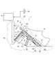
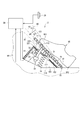
- FIG. 1 is a schematic view of a pedal device according to a first embodiment
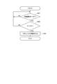
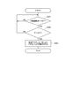
- FIG. 2 is a flow of a process of fixing the pedal pad of the pedal device according to the first embodiment
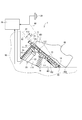
- FIG. 3 is a schematic view of the pedal device according to the first embodiment, in which the pedal pad is fixed
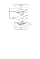
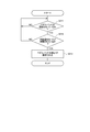
- FIG. 4 is a flow of a process of releasing the fixation of the pedal pad of the pedal device according to the first embodiment
- FIG. 5 is a schematic view of the pedal device according to the first embodiment, which is a schematic view when the fixing of the pedal pad is released
- FIG. 6 is a schematic view of a pedal device according to a second embodiment
- FIG. 1 is a schematic view of a pedal device according to a first embodiment
- FIG. 2 is a flow of a process of fixing the pedal pad of the pedal device according to the first embodiment
- FIG. 3 is a schematic view of the pedal device according to the first embodiment, in which the pedal pad is fixed
- FIG. 4 is a flow of a process of releasing the fix
- FIG. 7 is a flow of a process of fixing the pedal pad of the pedal device according to the second embodiment
- FIG. 8 is a schematic view of a pedal device according to a second embodiment, in which the pedal pad is fixed
- FIG. 9 is a flow of a process of releasing the fixation of the pedal pad of the pedal device according to the second embodiment
- FIG. 10 is a schematic view of the pedal device according to the second embodiment, which is a schematic view when the fixing of the pedal pad is released
- FIG. 11 is a schematic view of a pedal device according to the third embodiment.
- the accelerator device 1 as the "pedal device” is an input device operated by the driver as the "operator” of the vehicle in order to determine the opening degree of the throttle valve of the vehicle engine (not shown).
- the accelerator device 1 is an electronic type, and outputs a signal representing the amount of depression as the "operation amount" of the pedal pad 15.
- the drive of the throttle valve of the vehicle is controlled based on a signal output from the accelerator device 1 and other information.
- the accelerator device 1 includes a base portion 10, a pedal pad 15, a spring 18, a pad fixing portion 20, and an engine control unit (hereinafter referred to as "ECU") 28.
- the accelerator device 1 is provided in a place (not shown) of a vehicle equipped with the accelerator device 1 at a location where the driver can easily step on his / her foot 95.
- the toe of the driver's foot is 951, and the heel is 952.
- the accelerator device 1 is supported by a vehicle body 90, as shown in FIG.
- the base portion 10 is provided on the inner wall surface 901 of the vehicle body 90 so as to be immovable relative to the vehicle body 90.
- the base portion 10 is a box-like member, and has a space 110 in which the spring 18 and a part of the pad fixing portion 20 can be accommodated.
- the end surface 11 opposite to the inner wall surface 901 of the base portion 10 is formed to be inclined with respect to the inner wall surface 901 so as to be along the pedal pad 15 that has been stepped on.
- the pedal pad 15 is a substantially flat member. An end surface 151 of the pedal pad 15 opposite to the base portion 10 is formed to allow the driver's foot 95 to be placed thereon.
- the pedal pad 15 is provided so as to be movable relative to the base portion 10 by the driver's stepping operation.
- a rotary support 16 for rotatably supporting the pedal pad 15 is provided at the end of the pedal pad 15 on the side close to the heel 952.
- the rotation support portion 16 is provided on the inner wall surface 901. Thereby, the pedal pad 15 is rotatably supported centering around center R1 on the inner wall surface 901.
- the spring 18 is provided so as to be partially accommodated in the space 110 between the pedal pad 15 and the inner wall surface 901.
- the spring 18 is inserted into a through hole 111 formed in the end face 11 of the base portion 10.
- One end of the spring 18 is fixed to an end surface 152 of the pedal pad 15 on the base 10 side.
- the other end of the spring 18 is fixed to the inner wall surface 901.
- the spring 18 biases the pedal pad 15 in the direction in which the inner wall surface 901 and the pedal pad 15 are separated.
- the pad fixing portion 20 is partially accommodated in the space 110 between the pedal pad 15 and the inner wall surface 901.
- the pad fixing unit 20 includes a link member 21, a fixing force generation unit 22, a stroke detection unit 23, and a stroke restriction unit 24.
- One end of the link member 21 is connected to the end surface 152 of the pedal pad 15.
- the link member 21 is connected to the pedal pad 15 at a position farther from the rotary support 16 than the position at which the spring 18 is fixed to the pedal pad 15.
- the link member 21 is inserted into a through hole 112 formed in the end surface 11 of the base portion 10.
- the other end of the link member 21 is inserted into the fixing force generator 22.
- the fixing force generation unit 22 is a substantially cylindrical member fixed to the inner wall surface 901.
- the fixing force generation unit 22 is formed so that the other end of the link member 21 can be inserted into itself.
- the fixing force generation unit 22 is an insertion and removal mechanism of the core of a knock type ballpoint pen capable of centering and fixing of the core by pushing of one knock and pulling in of the core fixed by pushing of the next knock into the inside. Have the same mechanism as That is, the pad fixing portion 20 can mechanically fix the pedal pad 15 without an electrical signal.
- the fixing force generation unit 22 can not move the link member 21 with respect to the fixing force generation unit 22. Further, when the link member 21 is further inserted from the state in which the movement of the link member 21 with respect to the fixing force generation unit 22 is not possible, the movement of the link member 21 is enabled. Details of the operation of the fixing force generation unit 22 will be described later.
- the stroke detection unit 23 is provided on the pedal pad 15 side of the fixed force generation unit 22.
- the stroke detection unit 23 detects the length of the link member 21 inserted into the fixing force generation unit 22 as the stroke length of the link member 21.
- the stroke detection unit 23 outputs a signal corresponding to the stroke length to the electrically connected ECU 28.
- the stroke limiting unit 24 is provided on the pedal pad 15 side of the stroke detecting unit 23.
- the stroke limiting unit 24 can limit the length of the link member 21 inserted into the fixing force generation unit 22 based on a command from the ECU 28 that is electrically connected. The details of the operation of the stroke limiting unit 24 will be described later.
- the ECU 28 calculates the rotation angle ⁇ of the pedal pad 15 corresponding to the amount of depression of the pedal pad 15 by the driver based on the signal output from the stroke detection unit 23.
- the rotation angle ⁇ of the pedal pad 15 refers to a rotation angle centering on the center R1 with respect to the position of the imaginary line A0.
- the ECU 28 instructs the stroke limiting unit 24 whether or not to limit the length of the link member 21 inserted into the fixing force generation unit 22.
- the ECU 28 controls the state of the vehicle based on the calculated rotation angle ⁇ of the pedal pad 15, the operation content of the switch 29 which can select the operation mode of the vehicle, the operation mode of the vehicle equipped with the accelerator device 1, and the like.
- the pedal pad 15 When the pedal pad 15 is depressed from the state shown in FIG. 1, the pedal pad 15 rotates about the center R1 (the solid line arrow F11 in FIG. 1) and overlaps the virtual line A1. It is assumed that the rotation angle ⁇ of the pedal pad 15 at this time is the first rotation angle ⁇ 1 as the “first operation amount”, and the accelerator is fully open. When the accelerator device 1 is operated to control the opening degree of the throttle valve, the pedal pad 15 moves between the virtual line A0 and the virtual line A1.
- FIG. 2 shows the flow of the process of fixing the pedal pad 15.
- step (hereinafter, simply referred to as "S") 101 it is determined whether the operation mode of the vehicle equipped with the accelerator device 1 is the automatic operation mode.
- the driving mode of the vehicle in the first embodiment is defined as follows.
- the automatic driving mode is a driving mode in which the operation of the accelerator device 1 is unnecessary when traveling the vehicle.
- the automatic driving mode also includes a cruise control mode for keeping the traveling speed of the vehicle constant without operating the accelerator.
- a non-automatic operation mode which is an operation mode that requires the operation of the accelerator device 1 in causing the vehicle to travel.
- the ECU 28 determines whether the operation mode of the vehicle in which the accelerator device 1 is mounted is the automatic operation mode based on the content of the operation of the switch 29 by the driver. If it is determined that the driving mode of the vehicle is the automatic driving mode, the process proceeds to S102. If it is determined that the operation mode of the vehicle is not the automatic operation mode, that is, the non-automatic operation mode is determined, the determination of S101 is repeated.
- the pedal pad 15 rotates about the center R1.
- the link member 21 is inserted into the fixing force generation unit 22.
- the stroke detection unit 23 outputs a signal corresponding to the stroke length of the link member 21 to the ECU 28.
- the ECU 28 calculates the rotation angle ⁇ of the pedal pad 15 based on the signal output from the stroke detection unit 23.
- the ECU 28 calculates the operation amount of the driver's pedal pad 15 from the rotation angle ⁇ of the pedal pad 15, and controls the opening degree of the throttle valve. In the first embodiment, these operations are performed when the position of the pedal pad 15 is between the virtual line A0 and the virtual line A1.
- the ECU 28 When it is determined in S101 that the operation mode of the vehicle is the automatic operation mode, the ECU 28 outputs a command that does not restrict the length of the link member 21 inserted into the fixed force generation unit 22 to the stroke restriction unit 24. Thereby, the length of the link member 21 inserted into the fixing force generation unit 22 freely changes in accordance with the degree of depression of the pedal pad 15 by the driver.
- the ECU 28 outputs, to the stroke limiting unit 24, a command for limiting the length of the link member 21 inserted into the fixing force generating unit 22.
- the length of the link member 21 inserted into the fixing force generation unit 22 is limited. Therefore, the rotation angle ⁇ of the pedal pad 15 is limited to the first rotation angle ⁇ 1.
- the ECU 28 determines whether the calculated rotation angle ⁇ of the pedal pad 15 is larger than the first rotation angle ⁇ 1.
- the pedal pad 15 located between the virtual line A0 and the virtual line A1 is further depressed, the length of the link member 21 inserted into the fixing force generation unit 22 by the stroke restriction unit 24 is not restricted. Therefore, as shown in FIG. 3, the base unit 10 is closer to the base line 10 than in the state of overlapping the virtual line A1. At this time, the rotation angle ⁇ of the pedal pad 15 is larger than the first rotation angle ⁇ 1.
- the ECU 28 determines whether the rotation angle ⁇ of the pedal pad 15 is larger than the first rotation angle ⁇ 1 based on the signal output from the stroke detection unit 23. If it is determined that the rotation angle ⁇ of the pedal pad 15 is larger than the first rotation angle ⁇ 1, the process proceeds to S103. When it is determined that the rotation angle ⁇ of the pedal pad 15 is equal to or less than the first rotation angle ⁇ 1, the process returns to S101.
- the pedal pad 15 is fixed.
- the pedal pad 15 in the state shown in FIG. 3 is fixed in the state of FIG. 3 against the biasing force of the spring 18 by the fixing force generated by the fixing force generation unit 22 and overlaps the virtual line A2.
- the rotation angle ⁇ of the pedal pad 15 at this time is set to a second rotation angle ⁇ 2 as a “second operation amount”.
- the second rotation angle ⁇ 2 is an angle larger than the first rotation angle ⁇ 1.
- FIG. 4 shows the flow of the process of releasing the fixation of the pedal pad 15.
- the ECU 28 determines whether the pedal pad 15 is fixed based on the change in the rotation angle ⁇ of the pedal pad 15 to be calculated. If it is determined that the pedal pad 15 is fixed, the process proceeds to S112. If it is determined that the pedal pad 15 is not fixed, the determination of S111 is repeated.
- the ECU 28 determines whether the rotation angle ⁇ of the pedal pad 15 calculated by the ECU 28 is larger than the second rotation angle ⁇ 2.
- the state of the accelerator device 1 in the case of YES in S112 is shown in FIG. In FIG. 5, the position of the pedal pad 15 in the state of FIG.
- the pedal pad 15 in the state of FIG. 3 When the pedal pad 15 in the state of FIG. 3 is depressed, as shown in FIG. 5, the pedal pad 15 approaches the base portion 10 as compared with the state of FIG. 3 indicated by the two-dot chain line 15 (for example, the pedal pad 15 Is beyond the virtual line A2 in FIG. 5). At this time, the rotation angle ⁇ of the pedal pad 15 is larger than the second rotation angle ⁇ 2.
- the ECU 28 determines whether the rotation angle ⁇ of the pedal pad 15 is larger than the second rotation angle ⁇ 2 based on the signal output from the stroke detection unit 23. If it is determined that the rotation angle ⁇ of the pedal pad 15 is larger than the second rotation angle ⁇ 2, the process proceeds to S113. If it is determined that the rotation angle ⁇ of the pedal pad 15 is equal to or less than the second rotation angle ⁇ 2, the process returns to S111.
- the rotation angle ⁇ of the pedal pad 15 changes based on the signal output from the stroke detection unit 23.
- the ECU 28 detects that the rotation angle ⁇ of the pedal pad 15 is changing, the ECU 28 cancels the automatic driving mode and switches to the non-automatic driving mode.
- the ECU 28 outputs a command for limiting the length of the link member 21 inserted into the fixing force generating unit 22 to the stroke limiting unit 24.
- the rotation angle ⁇ of the pedal pad 15 is limited to the first rotation angle ⁇ 1.
- the pad fixing portion 20 can fix the pedal pad 15 relative to the base portion 10 so as to be immovable.
- the operation mode of the vehicle equipped with the accelerator device 1 is the automatic operation mode
- the foot 95 of the driver of the accelerator device 1 can be placed on the pedal pad 15 fixed by the pad fixing portion 20. Therefore, since the driver can rest his / her foot when the driver does not need to operate the accelerator device 1, the accelerator device 1 can reduce the burden on the driver's foot.
- the rotation angle ⁇ of the pedal pad 15 is larger than the second rotation angle ⁇ 2.
- the driver depresses the pedal pad 15 to release the fixing of the pedal pad 15 so that the accelerator device 1 can be operated.
- the accelerator device 1 can quickly switch from the automatic driving mode to the non-automatic driving mode.
- the pedal pad 15 can be mechanically fixed. As a result, the pedal pad 15 can be fixed or released relatively inexpensively.
- the pedal pad 15 is fixed when the rotation angle ⁇ of the pedal pad 15 is larger than the first rotation angle ⁇ 1. Thereby, in the automatic operation mode, the pedal pad 15 can be fixed only by the operation of the pedal pad 15. Therefore, in the accelerator device 1, the pedal pad 15 can be easily fixed.
- the stroke limiting unit 24 sets the length of the link member 21 inserted into the fixing force generation unit 22 when the operation mode of the vehicle is not the automatic operation mode according to the command of the ECU 28 Limit.
- the rotation angle ⁇ of the pedal pad 15 does not become larger than the first rotation angle ⁇ 1. Therefore, when the driving mode of the vehicle is not the automatic driving mode, it is possible to prevent the pedal pad 15 from being fixed unexpectedly.
- the second embodiment differs from the first embodiment in the configuration of the pad fixing portion.
- symbol is attached
- the accelerator device 2 includes a base portion 10, a pedal pad 15, a spring 18, a pad fixing portion 30, and an ECU 28.
- the pad fixing portion 30 is partially accommodated in the space 110 between the pedal pad 15 and the inner wall surface 901.
- the pad fixing unit 30 includes a link member 31, an electric actuator 32, and a stroke detection unit 23.
- the link member 31 is formed to have an arc shape of a virtual circle centered on the center R1.
- the link member 31 has a plurality of teeth on the radially outer side of the arc of the virtual circle.
- One end of the link member 31 is connected to the end surface 152 of the pedal pad 15.
- the link member 31 is connected to the pedal pad 15 at a position farther from the rotary support 16 than the position at which the spring 18 is fixed to the pedal pad 15.
- the other end of the link member 31 is inserted into the stroke detection unit 23 provided in the space 110.
- the electric actuator 32 is accommodated in the space 110 and electrically connected to the ECU 28. Driving of the electric actuator 32 is controlled by the ECU 28.
- the electric actuator 32 has a rotating shaft 321 and a gear 322.
- the gear 322 is rotatably provided integrally with the rotating shaft 321.
- the teeth of the gear 322 mesh with the teeth of the link member 31 as shown in FIG.
- FIG. 7 shows a flow of a process of fixing the pedal pad 15.
- the ECU 28 determines whether the calculated rotation angle ⁇ of the pedal pad 15 is larger than the third rotation angle ⁇ 3.
- FIG. 8 shows the accelerator device 2 in which the rotational angle ⁇ of the pedal pad 15 is at the third rotational angle ⁇ 3.
- the third rotation angle ⁇ 3 is a smaller angle than the first rotation angle ⁇ 1 defined in the first embodiment, and can be set variably.
- the rotation angle ⁇ of the pedal pad 15 is at the third rotation angle ⁇ 3, as shown in FIG. 8, the pedal pad 15 is at a position overlapping the virtual line A3 located between the virtual line A0 and the virtual line A1. .
- the pedal pad 15 overlapping the virtual line A0 is depressed to a position beyond the virtual line A3 (FIG. Solid arrow F21).
- the ECU 28 determines whether the rotation angle ⁇ of the pedal pad 15 is larger than the third rotation angle ⁇ 3 based on the signal output from the stroke detection unit 23. If it is determined that the rotation angle ⁇ of the pedal pad 15 is larger than the third rotation angle, the process proceeds to S203. When it is determined that the rotation angle ⁇ of the pedal pad 15 is equal to or less than the third rotation angle ⁇ 3, the process returns to S201.
- the pedal pad 15 is fixed by the electric actuator 32.
- the ECU 28 locks the electric actuator 32 so that the rotating shaft 321 does not rotate.
- the link member 31 can not move due to the reaction force of the electric actuator 32 because the teeth of the link member 31 mesh with the teeth of the gear 322.
- the pedal pad 15 to which the link member 31 is connected is fixed at a position beyond the imaginary line A3.
- FIG. 9 shows the flow of the process of releasing the fixation of the pedal pad 15.
- the ECU 28 determines whether the automatic operation mode is released. Specifically, the ECU 28 determines whether the driver switches the traveling mode by the switch 29 or not. If it is determined that the automatic operation mode is released, the process proceeds to S213. If it is determined that the automatic driving mode is not released, the determination of S211 is repeated.
- the pedal pad 15 can be fixed immovably relative to the base portion 10 by the pad fixing portion 30.
- the second embodiment exhibits the same effects as the effects (a), (b), (d) and (e) of the first embodiment.
- the ECU 28 controls the drive of the electric actuator 32 that generates a reaction force as a fixing force for fixing the pedal pad 15.
- the accelerator device 2 can fix the pedal pad 15 at an arbitrary rotation angle. Therefore, since the pedal pad 15 can be fixed at an angle optimum for the driver, the burden on the driver can be further reduced.
- the automatic operation mode can be released by the operation of the switch 29 so that the pedal pad 15 can be operated.
- the fixing of the pedal pad 15 can be released by an operation by the driver's hand capable of relatively quick movement.
- the pedal pad 15 can be quickly operated.
- the third embodiment differs from the second embodiment in that the pedal pad is provided with a contact detection unit.
- symbol is attached
- the accelerator device 3 includes a base portion 10, a pedal pad 15, a spring 18, a pad fixing portion 30, a pressure sensor 40 as a "contact detection portion", and an ECU 28.
- the pressure sensor 40 is provided on the end surface 151 of the pedal pad 15.
- the pressure sensor 40 is, for example, a capacitive switch, and is electrically connected to the ECU 28. When the foot 95 is placed on the pressure sensor 40, the pressure sensor 40 outputs a signal indicating that the foot 95 is placed to the ECU 28.
- the ECU 28 determines whether the foot 95 is placed on the pressure sensor 40. When the foot 95 is placed on the pressure sensor 40, the ECU 28 combines the signal output from the pressure sensor 40 with the signal representing the release of the automatic operation mode by the operation of the switch 29. Release the fixation.
- the ECU 28 does not release the fixation of the pedal pad 15 only by releasing the automatic operation mode by the operation of the switch 29. In this case, the ECU 28 releases the fixation of the pedal pad 15 based on the signal that the foot 95 is placed on the pressure sensor 40 output from the pressure sensor 40.
- the accelerator device 3 according to the third embodiment can fix the pedal pad 15 relative to the base portion 10 so as to be immovable relative to the base portion 10 by the pad fixing portion 30 having the electric actuator 32.
- 3rd embodiment has the same effect as 2nd embodiment.
- the ECU 28 releases the fixing of the pedal pad 15 by the signal output from the pressure sensor 40 and the release of the automatic operation mode by the operation of the switch 29.
- the "pedal device” is an accelerator device that controls the drive of the throttle valve of the vehicle.
- the field to which the “pedal device” of the present disclosure is applied is not limited thereto.
- the present invention may be applied to the operation of a brake or a clutch, and can be applied to the field of controlling various types of drive depending on the stepping amount of the operator who operates the pedal device.
- the mechanism for fixing the link member in the fixing force generation unit is a core insertion and removal mechanism in the knock type ballpoint pen.
- the mechanism for fixing the link member in the fixing force generation unit is not limited to this.
- it may be a mechanism that enables locking and unlocking in a step-in parking brake system.
- the rotation angle of the pedal pad when the accelerator device is fully opened is used as the first rotation angle ⁇ 1.
- the first rotation angle ⁇ 1 is not limited to this.
- the rotation angle may be larger than the rotation angle of the pedal pad when the accelerator device is fully opened.
- the first embodiment is provided with a stroke restricting portion which restricts the length of the link member inserted into the fixing force generating portion when the driving mode of the vehicle is not the automatic driving mode.
- the stroke limiting unit may not be provided.
- the ECU determines that the rotation angle of the pedal pad is a large angle compared to the third rotation angle ⁇ 3, the ECU locks the electric actuator so as to fix the pedal pad.
- the rotation angle of the pedal pad at which the ECU locks the electric actuator is not limited to this.
- a desired rotation angle of the pedal pad for reducing the burden on the driver is stored in advance in the ECU.
- the ECU drives the electric actuator such that the rotation angle of the pedal pad is the desired rotation angle. This can further reduce the burden on the driver.
- the third rotation angle is a smaller angle than the first rotation angle ⁇ 1.
- the third rotation angle is not limited to this.
- the angle may be larger than the first rotation angle ⁇ 1.
- the third rotation angle ⁇ 3 can be set arbitrarily.
- the ECU releases the automatic operation mode from the combination of the signal output from the pressure sensor and the signal output from the switch.
- the method of canceling the automatic operation mode in the third embodiment is not limited to this.
- the automatic operation mode may be canceled only by the signal output from the pressure sensor. This is because the pressure sensor outputs a signal indicating that a foot is placed on the pressure sensor, so that the driver can operate the accelerator device even if the automatic driving mode is released.
- the pressure sensor provided in the third embodiment may be applied to the first embodiment.
- this indication is not limited to such an embodiment, and can be carried out with various forms in the range which does not deviate from the gist.
Landscapes
- Engineering & Computer Science (AREA)
- Transportation (AREA)
- Mechanical Engineering (AREA)
- Physics & Mathematics (AREA)
- General Physics & Mathematics (AREA)
- Automation & Control Theory (AREA)
- Chemical & Material Sciences (AREA)
- Combustion & Propulsion (AREA)
- Auxiliary Drives, Propulsion Controls, And Safety Devices (AREA)
- Mechanical Control Devices (AREA)
- Braking Elements And Transmission Devices (AREA)
- Control Of Throttle Valves Provided In The Intake System Or In The Exhaust System (AREA)
- Arrangement And Mounting Of Devices That Control Transmission Of Motive Force (AREA)
Priority Applications (3)
| Application Number | Priority Date | Filing Date | Title |
|---|---|---|---|
| DE112018005184.6T DE112018005184T5 (de) | 2017-11-02 | 2018-10-19 | Pedalvorrichtung |
| CN201880071082.5A CN111295630B (zh) | 2017-11-02 | 2018-10-19 | 踏板装置 |
| US16/863,101 US11099596B2 (en) | 2017-11-02 | 2020-04-30 | Pedal device |
Applications Claiming Priority (2)
| Application Number | Priority Date | Filing Date | Title |
|---|---|---|---|
| JP2017-212612 | 2017-11-02 | ||
| JP2017212612A JP7098909B2 (ja) | 2017-11-02 | 2017-11-02 | ペダル装置 |
Related Child Applications (1)
| Application Number | Title | Priority Date | Filing Date |
|---|---|---|---|
| US16/863,101 Continuation US11099596B2 (en) | 2017-11-02 | 2020-04-30 | Pedal device |
Publications (1)
| Publication Number | Publication Date |
|---|---|
| WO2019087817A1 true WO2019087817A1 (ja) | 2019-05-09 |
Family
ID=66331881
Family Applications (1)
| Application Number | Title | Priority Date | Filing Date |
|---|---|---|---|
| PCT/JP2018/038978 Ceased WO2019087817A1 (ja) | 2017-11-02 | 2018-10-19 | ペダル装置 |
Country Status (5)
| Country | Link |
|---|---|
| US (1) | US11099596B2 (enExample) |
| JP (1) | JP7098909B2 (enExample) |
| CN (1) | CN111295630B (enExample) |
| DE (1) | DE112018005184T5 (enExample) |
| WO (1) | WO2019087817A1 (enExample) |
Families Citing this family (24)
| Publication number | Priority date | Publication date | Assignee | Title |
|---|---|---|---|---|
| DE102018219487B4 (de) * | 2018-11-15 | 2021-07-29 | Audi Ag | Vorrichtung zum Betätigen von Bremse und Gas in einem Fahrzeug |
| JP2020131923A (ja) * | 2019-02-20 | 2020-08-31 | 本田技研工業株式会社 | 乗員姿勢調整装置およびペダル装置 |
| US11148646B2 (en) * | 2019-04-03 | 2021-10-19 | GM Global Technology Operations LLC | Retractable pedal assembly for a vehicle |
| US11414057B2 (en) * | 2019-04-03 | 2022-08-16 | GM Global Technology Operations LLC | Retractable pedal assembly for a vehicle |
| WO2020218454A1 (ja) | 2019-04-26 | 2020-10-29 | 住友建機株式会社 | 表示装置、ショベル、情報処理装置 |
| KR20200132430A (ko) * | 2019-05-17 | 2020-11-25 | 현대자동차주식회사 | 전기 차량의 가속페달 안내 방법 및 시스템 |
| JP7494502B2 (ja) * | 2020-03-13 | 2024-06-04 | 株式会社デンソー | アクセル装置 |
| KR20210131007A (ko) * | 2020-04-23 | 2021-11-02 | 현대자동차주식회사 | 자율주행 차량용 폴더블 페달장치 |
| KR102884624B1 (ko) * | 2020-06-23 | 2025-11-11 | 현대자동차주식회사 | 폴더블 페달장치를 구비한 자율주행 차량의 수동운전모드 전환시 제어방법 |
| KR102771521B1 (ko) * | 2020-08-12 | 2025-02-21 | 현대자동차주식회사 | 자율주행 차량용 폴더블 브레이크페달장치 |
| KR102855902B1 (ko) * | 2020-11-18 | 2025-09-05 | 현대자동차주식회사 | 폴더블 페달장치의 작동 안정화 시스템 |
| KR102845703B1 (ko) * | 2021-03-08 | 2025-08-12 | 현대자동차주식회사 | 차량용 폴더블 페달장치 |
| KR20220136745A (ko) * | 2021-04-01 | 2022-10-11 | 현대자동차주식회사 | 차량용 폴더블 페달장치 |
| EP4075233A1 (en) * | 2021-04-15 | 2022-10-19 | Volvo Car Corporation | Pedal system |
| KR20220162516A (ko) * | 2021-06-01 | 2022-12-08 | 현대자동차주식회사 | 차량용 폴더블 페달장치 |
| KR20220164863A (ko) * | 2021-06-04 | 2022-12-14 | 현대자동차주식회사 | 자율주행 차량용 폴더블 페달장치 및 이의 작동 제어방법 |
| JP7639617B2 (ja) | 2021-08-25 | 2025-03-05 | 株式会社デンソー | アクセルペダルシステム |
| KR20230086855A (ko) * | 2021-12-08 | 2023-06-16 | 현대자동차주식회사 | 차량용 폴더블 페달장치 |
| KR20230128192A (ko) * | 2022-02-25 | 2023-09-04 | 현대자동차주식회사 | 차량용 폴더블 페달장치 |
| KR20230128193A (ko) * | 2022-02-25 | 2023-09-04 | 현대자동차주식회사 | 차량용 폴더블 페달장치 |
| CN114537436A (zh) * | 2022-03-04 | 2022-05-27 | 阿波罗智能技术(北京)有限公司 | 自动驾驶车辆的控制方法、装置、设备和自动驾驶车辆 |
| CN118056722A (zh) * | 2022-11-21 | 2024-05-21 | 沃尔沃汽车公司 | 车辆操作装置、车辆系统和车辆制动系统 |
| KR20240084570A (ko) * | 2022-12-06 | 2024-06-13 | 현대자동차주식회사 | 차량용 페달장치 |
| US12337809B2 (en) | 2023-03-14 | 2025-06-24 | Ford Global Technologies, Llc | Stowable vehicle pedal system and method |
Citations (5)
| Publication number | Priority date | Publication date | Assignee | Title |
|---|---|---|---|---|
| JP2000054860A (ja) * | 1998-08-10 | 2000-02-22 | Denso Corp | 自動走行制御装置及びペダル反力調整器並びに記録媒体 |
| JP2002323930A (ja) * | 2001-04-25 | 2002-11-08 | Hitachi Ltd | 車両のペダル装置及びそれを備えた車両 |
| JP2007022395A (ja) * | 2005-07-19 | 2007-02-01 | Toyota Motor Corp | ペダル反力制御装置 |
| JP2009251773A (ja) * | 2008-04-03 | 2009-10-29 | Toyota Motor Corp | 足踏み式操作装置 |
| JP2010228651A (ja) * | 2009-03-27 | 2010-10-14 | Nissan Motor Co Ltd | 車両用アクセルペダル反力付与装置及びその方法 |
Family Cites Families (11)
| Publication number | Priority date | Publication date | Assignee | Title |
|---|---|---|---|---|
| JPS6445929A (en) * | 1987-08-12 | 1989-02-20 | Hitachi Ltd | Electronic type throttle control device for internal combustion engine |
| JP2007269122A (ja) | 2006-03-30 | 2007-10-18 | Iseki & Co Ltd | 作業車両のクルーズコントロール装置 |
| KR100781288B1 (ko) * | 2006-05-16 | 2007-11-30 | 윤대한 | 차량용 정속 주행 장치 |
| JP5087358B2 (ja) * | 2007-10-01 | 2012-12-05 | 日立建機株式会社 | 作業車両のペダルロック制御装置 |
| JP6591873B2 (ja) * | 2015-11-20 | 2019-10-16 | 日産自動車株式会社 | フロア昇降装置 |
| JP2017212612A (ja) | 2016-05-26 | 2017-11-30 | 京セラ株式会社 | 圧電デバイス及びその製造方法 |
| JP6761323B2 (ja) * | 2016-10-31 | 2020-09-23 | 修一 田山 | 車輌用アクセルペダル装置 |
| JP2018149933A (ja) | 2017-03-14 | 2018-09-27 | オムロン株式会社 | 制御装置、プログラム、支援装置および支援方法 |
| US10739809B2 (en) * | 2018-03-28 | 2020-08-11 | GM Global Technology Operations LLC | Pedal assembly for a vehicle |
| US11617682B2 (en) * | 2018-05-18 | 2023-04-04 | Alcon Inc. | Surgical foot pedal device having force feedback |
| US11414057B2 (en) * | 2019-04-03 | 2022-08-16 | GM Global Technology Operations LLC | Retractable pedal assembly for a vehicle |
-
2017
- 2017-11-02 JP JP2017212612A patent/JP7098909B2/ja active Active
-
2018
- 2018-10-19 CN CN201880071082.5A patent/CN111295630B/zh active Active
- 2018-10-19 WO PCT/JP2018/038978 patent/WO2019087817A1/ja not_active Ceased
- 2018-10-19 DE DE112018005184.6T patent/DE112018005184T5/de active Pending
-
2020
- 2020-04-30 US US16/863,101 patent/US11099596B2/en active Active
Patent Citations (5)
| Publication number | Priority date | Publication date | Assignee | Title |
|---|---|---|---|---|
| JP2000054860A (ja) * | 1998-08-10 | 2000-02-22 | Denso Corp | 自動走行制御装置及びペダル反力調整器並びに記録媒体 |
| JP2002323930A (ja) * | 2001-04-25 | 2002-11-08 | Hitachi Ltd | 車両のペダル装置及びそれを備えた車両 |
| JP2007022395A (ja) * | 2005-07-19 | 2007-02-01 | Toyota Motor Corp | ペダル反力制御装置 |
| JP2009251773A (ja) * | 2008-04-03 | 2009-10-29 | Toyota Motor Corp | 足踏み式操作装置 |
| JP2010228651A (ja) * | 2009-03-27 | 2010-10-14 | Nissan Motor Co Ltd | 車両用アクセルペダル反力付与装置及びその方法 |
Also Published As
| Publication number | Publication date |
|---|---|
| CN111295630A (zh) | 2020-06-16 |
| CN111295630B (zh) | 2022-11-08 |
| US20200257329A1 (en) | 2020-08-13 |
| DE112018005184T5 (de) | 2020-06-10 |
| US11099596B2 (en) | 2021-08-24 |
| JP7098909B2 (ja) | 2022-07-12 |
| JP2019086881A (ja) | 2019-06-06 |
Similar Documents
| Publication | Publication Date | Title |
|---|---|---|
| WO2019087817A1 (ja) | ペダル装置 | |
| KR101612368B1 (ko) | 드라이브 바이 와이어 시스템용 레버 | |
| US11192529B2 (en) | Vehicle control device | |
| US11597407B2 (en) | Vehicle control system | |
| JP7125196B2 (ja) | シフト装置 | |
| WO2016140262A1 (ja) | 反力出力装置 | |
| JP2007009946A (ja) | 車両制御システム | |
| CN104145068A (zh) | 车辆的把手装置 | |
| WO2024070632A1 (ja) | 反力付与装置 | |
| JP2006155228A (ja) | 入力操作装置 | |
| US11001235B2 (en) | Vehicle control device | |
| JP2007128243A (ja) | 入力操作装置 | |
| JP2025081170A (ja) | 車両用パーキングロック機構の制御装置 | |
| JP2010167954A (ja) | 入力装置 | |
| JP2009104384A (ja) | 入力操作装置 | |
| JP2018205856A (ja) | 運転補助装置 | |
| JP4408473B2 (ja) | 車両用変速操作装置のシフトロック解除機構 | |
| JP4665554B2 (ja) | ステアリングコラム跳ね上げシステム | |
| JP2012104084A (ja) | 車両操作ペダル | |
| JP6030037B2 (ja) | 反力出力装置 | |
| JP2004342019A (ja) | 力覚付与型入力装置 | |
| JP2015095165A (ja) | 反力出力装置 | |
| JP2006155057A (ja) | 入力操作装置 | |
| JP2000255397A (ja) | 駐車用ブレーキ装置 | |
| CN110259933A (zh) | 换挡系统和方法 |
Legal Events
| Date | Code | Title | Description |
|---|---|---|---|
| 121 | Ep: the epo has been informed by wipo that ep was designated in this application |
Ref document number: 18872973 Country of ref document: EP Kind code of ref document: A1 |
|
| 122 | Ep: pct application non-entry in european phase |
Ref document number: 18872973 Country of ref document: EP Kind code of ref document: A1 |