WO2019078255A1 - アクチュエータ - Google Patents
アクチュエータ Download PDFInfo
- Publication number
- WO2019078255A1 WO2019078255A1 PCT/JP2018/038671 JP2018038671W WO2019078255A1 WO 2019078255 A1 WO2019078255 A1 WO 2019078255A1 JP 2018038671 W JP2018038671 W JP 2018038671W WO 2019078255 A1 WO2019078255 A1 WO 2019078255A1
- Authority
- WO
- WIPO (PCT)
- Prior art keywords
- housing
- connector
- holding member
- fitting portion
- insertion hole
- Prior art date
- Legal status (The legal status is an assumption and is not a legal conclusion. Google has not performed a legal analysis and makes no representation as to the accuracy of the status listed.)
- Ceased
Links
Images


Classifications
-
- H—ELECTRICITY
- H02—GENERATION; CONVERSION OR DISTRIBUTION OF ELECTRIC POWER
- H02K—DYNAMO-ELECTRIC MACHINES
- H02K5/00—Casings; Enclosures; Supports
- H02K5/04—Casings or enclosures characterised by the shape, form or construction thereof
- H02K5/22—Auxiliary parts of casings not covered by groups H02K5/06-H02K5/20, e.g. shaped to form connection boxes or terminal boxes
- H02K5/225—Terminal boxes or connection arrangements
-
- F—MECHANICAL ENGINEERING; LIGHTING; HEATING; WEAPONS; BLASTING
- F01—MACHINES OR ENGINES IN GENERAL; ENGINE PLANTS IN GENERAL; STEAM ENGINES
- F01D—NON-POSITIVE DISPLACEMENT MACHINES OR ENGINES, e.g. STEAM TURBINES
- F01D17/00—Regulating or controlling by varying flow
- F01D17/10—Final actuators
-
- F—MECHANICAL ENGINEERING; LIGHTING; HEATING; WEAPONS; BLASTING
- F01—MACHINES OR ENGINES IN GENERAL; ENGINE PLANTS IN GENERAL; STEAM ENGINES
- F01D—NON-POSITIVE DISPLACEMENT MACHINES OR ENGINES, e.g. STEAM TURBINES
- F01D17/00—Regulating or controlling by varying flow
- F01D17/20—Devices dealing with sensing elements or final actuators or transmitting means between them, e.g. power-assisted
-
- F—MECHANICAL ENGINEERING; LIGHTING; HEATING; WEAPONS; BLASTING
- F01—MACHINES OR ENGINES IN GENERAL; ENGINE PLANTS IN GENERAL; STEAM ENGINES
- F01D—NON-POSITIVE DISPLACEMENT MACHINES OR ENGINES, e.g. STEAM TURBINES
- F01D25/00—Component parts, details, or accessories, not provided for in, or of interest apart from, other groups
- F01D25/34—Turning or inching gear
-
- F—MECHANICAL ENGINEERING; LIGHTING; HEATING; WEAPONS; BLASTING
- F02—COMBUSTION ENGINES; HOT-GAS OR COMBUSTION-PRODUCT ENGINE PLANTS
- F02B—INTERNAL-COMBUSTION PISTON ENGINES; COMBUSTION ENGINES IN GENERAL
- F02B37/00—Engines characterised by provision of pumps driven at least for part of the time by exhaust
- F02B37/12—Control of the pumps
- F02B37/18—Control of the pumps by bypassing exhaust from the inlet to the outlet of turbine or to the atmosphere
- F02B37/183—Arrangements of bypass valves or actuators therefor
- F02B37/186—Arrangements of actuators or linkage for bypass valves
-
- H—ELECTRICITY
- H02—GENERATION; CONVERSION OR DISTRIBUTION OF ELECTRIC POWER
- H02K—DYNAMO-ELECTRIC MACHINES
- H02K11/00—Structural association of dynamo-electric machines with electric components or with devices for shielding, monitoring or protection
- H02K11/20—Structural association of dynamo-electric machines with electric components or with devices for shielding, monitoring or protection for measuring, monitoring, testing, protecting or switching
- H02K11/21—Devices for sensing speed or position, or actuated thereby
- H02K11/215—Magnetic effect devices, e.g. Hall-effect or magneto-resistive elements
-
- H—ELECTRICITY
- H02—GENERATION; CONVERSION OR DISTRIBUTION OF ELECTRIC POWER
- H02K—DYNAMO-ELECTRIC MACHINES
- H02K5/00—Casings; Enclosures; Supports
- H02K5/04—Casings or enclosures characterised by the shape, form or construction thereof
- H02K5/10—Casings or enclosures characterised by the shape, form or construction thereof with arrangements for protection from ingress, e.g. water or fingers
-
- H—ELECTRICITY
- H02—GENERATION; CONVERSION OR DISTRIBUTION OF ELECTRIC POWER
- H02K—DYNAMO-ELECTRIC MACHINES
- H02K7/00—Arrangements for handling mechanical energy structurally associated with dynamo-electric machines, e.g. structural association with mechanical driving motors or auxiliary dynamo-electric machines
- H02K7/08—Structural association with bearings
-
- H—ELECTRICITY
- H02—GENERATION; CONVERSION OR DISTRIBUTION OF ELECTRIC POWER
- H02K—DYNAMO-ELECTRIC MACHINES
- H02K7/00—Arrangements for handling mechanical energy structurally associated with dynamo-electric machines, e.g. structural association with mechanical driving motors or auxiliary dynamo-electric machines
- H02K7/10—Structural association with clutches, brakes, gears, pulleys or mechanical starters
- H02K7/116—Structural association with clutches, brakes, gears, pulleys or mechanical starters with gears
Definitions
- the present disclosure relates to an actuator that drives a supercharger control valve.
- an actuator connected to a supercharging pressure control valve via, for example, a link mechanism and the like to control the supercharging pressure by adjusting the valve opening.
- the actuator disclosed in Patent Document 1 decelerates the rotation of the motor by a reduction gear and outputs it from an output shaft.
- the rotation angle of the output shaft is detected by a rotation angle sensor.
- the output shaft is supported by the housing and the cover. Reinforcing ribs are formed on the portions of the resin cover to which the reaction force generated with the operation of the actuator is applied.
- This indication is made in view of the above-mentioned point, and the purpose is to provide the actuator by which strength improvement of the support member of an output shaft was aimed at, having the composition which holds electric wiring. .
- the actuator of the present disclosure includes a motor, an output shaft, a speed reduction unit, a rotation angle sensor, a housing, and a wire holding member.
- the decelerating unit decelerates the rotation of the motor and transmits it to the output shaft.
- the rotation angle sensor detects the rotation angle of the output shaft.
- the housing accommodates the motor and the reduction gear, and supports the output shaft.
- the wiring holding member integrally holds the detection portion of the rotation angle sensor, and the electric wiring of the motor and the detection portion, and is a separate member from the housing.
- the housing has a connector insertion hole penetrating into and out of the housing.
- the wire holding member includes an end portion of the electric wire, and forms a connector portion which protrudes from the inside of the housing to the outside of the housing through the connector insertion hole.
- the housing and the wire holding member can be formed of separate members, and materials suitable for each can be selected.
- the housing as the support member of the output shaft from a high strength material such as metal or engineering plastic, for example, the strength can be ensured against a relatively large load due to exhaust pulsation.
- the wiring holding member an insulator, it is possible to hold them while preventing a short circuit of the electric wiring. Further, by taking out the electric wiring of the motor and the detection unit to the outside through the connector unit, only one sealing portion between the wiring holding member and the housing is required.
- FIG. 1 is a schematic view of an intake and exhaust portion of an engine to which an actuator according to a first embodiment is applied
- Fig. 2 is an explanatory view of a supercharger
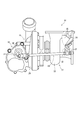
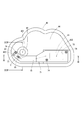
- FIG. 3 is a perspective view of the actuator
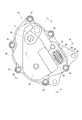
- FIG. 4 is a top view of the actuator
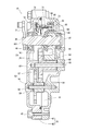
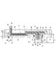
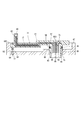
- 5 is a cross-sectional view taken along the line V-V of FIG. 6
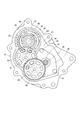
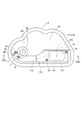
- VI-VI of FIG. 7 is a view showing a state in which the second housing portion etc. of the actuator of FIG. 4 is removed
- FIG. 8 is a view of the second housing part and the wiring holding member etc.
- FIG. 9 is a cross-sectional view taken along line IX-IX of FIG. 10 is a cross-sectional view taken along line XX in FIG. 11 is a cross-sectional view taken along line XI-XI of FIG.
- FIG. 12 is a view showing a state in the middle of assembling the second housing portion and the wire holding member
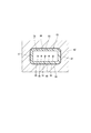
- FIG. 13 is a diagram corresponding to FIG. 8 and illustrates two virtual straight lines and the like
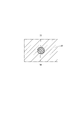
- 14 is a cross-sectional view taken along line XIV-XIV of FIG.
- FIG. 15 is a view showing how the fitting portion regulates the rotation of the wiring holding member centering on the positioning projection;
- FIG. 16 is a view showing how the fitting portion performs rotation restriction of the wiring holding member centering on the positioning projection in the comparative embodiment
- FIG. 17 is a cross-sectional view showing a connector portion and a connector insertion hole of an actuator according to a second embodiment
- FIG. 18 is a view of the second housing portion, the wire holding member, and the like of the actuator according to the third embodiment, as viewed from the inside of the second housing portion
- FIG. 19 is a cross-sectional view taken along line XIX-XIX in FIG.
- the actuator 10 according to the first embodiment is applied to an engine 11 which is a power source for traveling a vehicle.
- the engine 11 is provided with an intake passage 12 for introducing intake air into the cylinder of the engine 11 and an exhaust passage 13 for discharging exhaust gas generated in the cylinder to the atmosphere.
- An intake compressor 15 of the turbocharger 14 and a throttle valve 16 for adjusting the amount of intake air supplied to the engine 11 are provided in the middle of the intake passage 12.
- an exhaust turbine 17 of the supercharger 14 and a catalyst 18 for purifying exhaust gas are provided in the middle of the exhaust passage 13.
- the catalyst 18 is a well-known three-way catalyst adopting a monolithic structure, and by raising the temperature to an activation temperature, the harmful substances contained in the exhaust gas are purified by an oxidation action and a reduction action.
- the exhaust turbine 17 includes a turbine wheel 21 rotationally driven by exhaust gas discharged from the engine 11, and a spiral-shaped turbine housing 22 accommodating the turbine wheel 21.
- the intake compressor 15 includes a compressor wheel 23 that rotates in response to the rotational force of the turbine wheel 21 and a spiral compressor housing 24 that accommodates the compressor wheel 23.
- the turbine housing 22 is provided with a bypass passage 25 for passing exhaust gas around the turbine wheel 21.
- the bypass passage 25 leads the exhaust gas flowing into the turbine housing 22 directly to the exhaust outlet of the turbine housing 22.
- the bypass passage 25 can be opened and closed by the waste gate valve 26.
- the waste gate valve 26 is a swing valve rotatably supported by a valve shaft 27 inside the turbine housing 22.
- the turbocharger 14 is provided with an actuator 10.
- the actuator 10 is attached to an intake compressor 15 remote from the exhaust turbine 17 for the purpose of avoiding the thermal influence of the exhaust gas.
- the supercharger 14 is provided with a link mechanism 29 for transmitting the output of the actuator 10 to the waste gate valve 26.
- the link mechanism 29 is a so-called four-bar link, and the actuator lever 31 which is rotationally operated by the actuator 10, the valve lever 32 coupled to the valve shaft 27, and the rotational torque applied to the actuator lever 31 And a rod 33 for transmitting to the lever 32.
- the actuator 10 is controlled by an ECU (engine control unit) 34 mounted with a microcomputer. Specifically, the ECU 34 adjusts the opening degree of the waste gate valve 26 at high rotation of the engine 11 or the like to control the supercharging pressure by the turbocharger 14. Further, the ECU 34 warms up the catalyst 18 by fully opening the waste gate valve 26 when the temperature of the catalyst 18 has not reached the activation temperature, such as immediately after a cold start. As a result, the high temperature exhaust gas which has not been deprived of heat by the turbine wheel 21 can be introduced to the catalyst 18, and the catalyst 18 can be warmed up promptly.
- the ECU 34 engine control unit 34 mounted with a microcomputer. Specifically, the ECU 34 adjusts the opening degree of the waste gate valve 26 at high rotation of the engine 11 or the like to control the supercharging pressure by the turbocharger 14. Further, the ECU 34 warms up the catalyst 18 by fully opening the waste gate valve 26 when the temperature of the catalyst 18 has not reached the activation temperature, such as immediately after a cold start. As a result
- the actuator 10 includes a housing 35 attached to the intake compressor 15, a motor 36 assembled to the housing 35, a speed reduction unit 37, an output shaft 38, and a rotation angle sensor 39.
- the housing 35 has a first housing portion 41 and a second housing portion 42.
- the second housing portion 42 is fastened to the first housing portion 41 by a fastening member 43. Further, the first housing portion 41 forms a housing space 44 together with the second housing portion 42.
- the motor 36 is accommodated in a housing 35. Specifically, the motor 36 is inserted into a motor insertion hole 46 formed in the first housing portion 41, and is fixed to the first housing portion 41 by a screw 47. A wave washer 45 is installed between the motor 36 and the bottom of the motor insertion hole 46.
- the motor 36 may be, for example, a well-known direct current motor or a well-known stepping motor regardless of its type.
- the output shaft 38 is rotatably supported by a bearing 48 provided in the first housing portion 41 and a bearing 49 provided in the second housing portion 42.
- One end of the output shaft 38 extends out of the housing 35.
- the actuator lever 31 is fixed to the output shaft outside the housing 35.
- a plug 50 is press-fit into a portion on the extension of the other end side of the output shaft 38 in the first housing portion 41.
- the reduction gear unit 37 is a parallel shaft reduction gear that decelerates the rotation of the motor 36 and transmits it to the output shaft 38, and includes the pinion gear 51, the first intermediate gear 52, and the second intermediate gear.
- a gear 53 and a final gear 54 are provided.
- the pinion gear 51 is fixed to a motor shaft 55 of the motor 36.
- the first intermediate gear 52 has a first large diameter external gear 57 engaged with the pinion gear 51, and a first small diameter external gear 58 smaller than the first large diameter external gear 57. It is rotatably supported by the first metal shaft 56.
- First washers 59 are provided between the first intermediate gear 52 and the first housing portion 41 and between the first intermediate gear 52 and the second housing portion 42, respectively.
- the second intermediate gear 53 has a second large diameter external gear 62 engaged with the first small diameter external gear 58 and a second small diameter external gear 63 smaller than the second large diameter external gear 62. It is rotatably supported by the second metal shaft 61. Second washers 60 are provided between the second intermediate gear 53 and the first housing portion 41 and between the second intermediate gear 53 and the second housing portion 42, respectively.
- the final gear 54 is fixed to the output shaft 38 and meshes with the second small diameter external tooth portion 63.
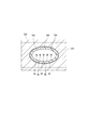
- the rotation angle sensor 39 is a non-contact type sensor that detects the rotation angle of the output shaft 38, and includes a magnetic circuit unit 64 and a detection unit 65.
- the magnetic circuit unit 64 includes magnets 66 and 67 as magnetic flux generating units and yokes 68 and 69 as magnetic flux transmitting units.
- the magnets 66 and 67 and the yokes 68 and 69 form an arc-shaped closed magnetic circuit in the axial direction of the output shaft 38.
- the magnetic circuit section 64 is held by a nonmagnetic magnetic circuit holding member 73 and rotates integrally with the output shaft 38.
- the detection unit 65 is, for example, a Hall IC, and is disposed inside the closed magnetic circuit of the magnetic circuit unit 64.
- the detection unit 65 is fixed to the housing 35.
- the basic applications and functions of the magnetic circuit unit 64 and the detection unit 65 are the same as those disclosed in Japanese Patent Laid-Open No. 2014-126548.
- the rotation angle of the output shaft 38 detected by the rotation angle sensor 39 is output to the ECU 34 (see FIG. 1).
- the actuator 10 includes a detection unit 65, and a wiring holding member 71 that integrally holds the motor 36 and the electric wiring 72 of the detection unit 65.
- the wire holding member 71 is a separate member from the housing 35, and the material is different.
- the first housing portion 41 and the second housing portion 42 are made of, for example, a metal such as an aluminum alloy.
- the wiring holding member 71 is an insulator and made of resin.
- the wiring holding member 71 is an insert-molded product integrated with the detection unit 65 and the electrical wiring 72, and is fixed to the second housing portion 42 by a screw 74 as a coupling member.
- the second housing portion 42 has a connector insertion hole 76 penetrating to the inside and the outside of the housing 35, and a positioning hole 77 formed in the inner wall.
- the wiring holding member 71 has a main body 81 formed along the inner wall of the second housing 42, and a sensor holding portion 82 protruding from the main body 81, a connector 83, and a positioning projection 84. .
- the sensor holding portion 82 protrudes toward the first housing portion side, and holds the detection portion 65.
- the positioning projection 84 is fitted in the positioning hole 77.
- the cross-sectional shape orthogonal to the insertion direction of the positioning projection 84 into the positioning hole 77 is circular.
- the insertion direction of the positioning projection 84 into the positioning hole 77 is a direction parallel to the center AX2 of the positioning projection 84.
- the gap between the positioning projection 84 and the positioning hole 77 is illustrated larger than the actual size in order to make the configuration easy to understand.
- the connector portion 83 protrudes from the inside of the housing 35 to the outside of the housing 35 through the connector insertion hole 76.
- the connector portion 83 has a fitting portion 85 fitted in the connector insertion hole 76.
- the cross-sectional shape orthogonal to the insertion direction of the fitting portion 85 into the connector insertion hole 76 is non-circular.
- the insertion direction of the fitting portion 85 into the connector insertion hole 76 coincides with the extension direction of the connector portion 83, that is, the protrusion direction.
- the front end portion of the connector portion 83 is one size smaller than the fitting portion 85 but basically has the same cross-sectional shape as the fitting portion 85.
- the gap between the fitting portion 85 and the connector insertion hole 76 is illustrated to be larger than the actual size in order to make the configuration easy to understand.
- the cross-sectional shape of the fitting portion 85 is a rectangular shape with rounded corners. Specifically, the cross-sectional shape of the fitting portion 85 has a pair of first straight portions 86 parallel to each other, and a pair of second straight portions 87 parallel to each other and orthogonal to the first straight portions 86. It is a shape.
- the connector portion 83 and the positioning protrusion 84 are inserted into the connector insertion hole 76 or the positioning hole 77 from the inside of the second housing portion 42.
- the distance L1 from the insertion end 91 of the connector portion 83 to the insertion opening 92 of the connector insertion hole 76 is longer than the distance L2 from the insertion end 93 of the positioning projection 84 to the insertion opening 94 of the positioning hole 77.
- the distance L3 from the insertion tip 96 of the fitting portion 85 to the insertion opening 92 of the connector insertion hole 76 is also longer than the distance L2.
- the tip of the connector portion 83 is a connector before the positioning protrusion 84 reaches the positioning hole 77 as shown in FIG. Then, the fitting portion 85 is fitted into the connector insertion hole 76.
- the screw 74 is inserted into the wire holding member 71 and the second housing portion 42.
- the insertion direction of the screw 74 at this time is the same as the direction in which the wire holding member 71 is combined with the second housing portion 42. That is, the insertion direction of the fitting portion 85 into the connector insertion hole 76, the insertion direction of the positioning projection 84 into the positioning hole 77, and the insertion direction of the screw 74 into the wiring holding member 71 and the second housing portion 42 are the same. It is.
- the first virtual straight line VL1 and the second virtual straight line VL2 shown in FIG. 13 are defined.
- the first virtual straight line VL1 is a virtual straight line connecting the center AX2 of the positioning protrusion 84 and the center AX3 of the fitting portion 85 in a direction in which the fitting portion 85 is inserted into the connector insertion hole 76.
- the second virtual straight line VL2 is a virtual straight line which is orthogonal to the first virtual straight line VL1 and passes through the center C of the detection unit 65.
- An intersection point p1 of the first virtual straight line VL1 and the second virtual straight line VL2 is located between the center AX1 and the center AX2.
- the width W1 in the direction along the first virtual straight line VL1 is longer than the width W2 in the direction orthogonal to the first virtual straight line VL1.
- the connector terminals 95 are arranged in the longitudinal direction of the cross section of the connector portion 83.
- the arrangement direction of the connector terminals 95 and the direction along the first virtual straight line VL1 substantially coincide with each other.
- the longitudinal direction of the cross section of the connector portion 83 is directed to the positioning projection 84.
- annular seal member 97 is provided in an annular gap between the inner wall of the connector insertion hole 76 and the fitting portion 85 of the connector portion 83.
- the seal member 97 seals between the outside of the housing 35 and the housing space 44.
- the annular groove 98 is formed in the fitting portion 85.
- the seal member 97 is located in the annular groove 98 and is provided to surround the entire circumference of the connector portion 83.
- the seal member 97 is compressed by being sandwiched between the inner wall of the connector insertion hole 76 and the connector portion 83.
- the compression direction of the seal member 97 is a direction orthogonal to the insertion direction of the connector portion 83, and is a direction in which the inner wall of the connector insertion hole 76 and the connector portion 83 face each other.
- the wire holding member 71 overlaps the bearing 49 (that is, the bearing provided between one end of the output shaft 38 and the second housing portion 42) in the axial direction.
- the wiring holding member 71 is disposed so as to three-dimensionally cross the bearing 49.
- the actuator 10 includes the motor 36, the output shaft 38, the speed reduction unit 37, the rotation angle sensor 39, the housing 35, and the wiring holding member 71.
- the wiring holding member 71 integrally holds the detection portion 65 of the rotation angle sensor 39 and the electric wiring 72 of the motor 36 and the detection portion 65, and is a separate member from the housing 35.
- the second housing portion 42 of the housing 35 has a connector insertion hole 76 which penetrates into and out of the housing 35.
- the wire holding member 71 includes the end of the electrical wire 72 and forms a connector portion 83 which protrudes from the inside of the housing 35 through the connector insertion hole 76 to the outside of the housing 35.
- the housing 35 and the wire holding member 71 are formed as separate members, and materials suitable for each are selected.
- the second housing portion 42 is formed as a support member for the output shaft 38 from a high strength material such as an aluminum alloy, for example, the strength against a relatively large load due to the exhaust pulsation can be ensured.
- the wire holding member 71 as an insulator, it is possible to hold the electric wires 72 while preventing a short circuit. Further, by taking out the electric wiring 72 of the motor 36 and the detection unit 65 to the outside through the connector unit 83, only one sealing portion between the wiring holding member 71 and the housing 35 is required.
- the connector portion 83 has a fitting portion 85 fitted in the connector insertion hole 76.
- the housing 35 has a positioning hole 77, and the wiring holding member 71 has a positioning projection 84 fitted in the positioning hole 77.
- the intersection point p1 of the first virtual straight line VL1 and the second virtual straight line VL2 is located between the center AX2 of the positioning projection 84 and the center AX3 of the fitting portion 85.
- the amount of variation in the position within the range is greater than the position out of the range between the center AX2 of the positioning protrusion 84 and the center AX3 of the fitting portion 85 Becomes smaller. Therefore, the rotation angle detection accuracy by the detection unit 65 can be improved by providing the detection unit 65 within the above range.
- the cross-sectional shape orthogonal to the insertion direction of the positioning projection 84 into the positioning hole 77 is circular.
- the cross-sectional shape orthogonal to the insertion direction of the connector portion 83 into the connector insertion hole 76 is non-circular.
- the distance L1 and the distance L3 are longer than the distance L2.
- the positioning projection 84 can be fitted into the positioning hole 77 smoothly.
- the cross-sectional shape orthogonal to the insertion direction of the fitting portion 85 into the connector insertion hole 76 is the first straight portion 86, which is parallel to the pair of first straight portions 86 parallel to each other. And a pair of second straight portions 87 orthogonal to each other. Accordingly, the fitting portion 85 has a simple shape, the dimensional accuracy is enhanced, and the positioning accuracy of the second housing portion 42 and the wiring holding member 71 can be improved.
- the width W1 of the fitting portion 85 in the direction along the first virtual straight line VL1 is orthogonal to the first virtual straight line VL1 in the insertion direction of the fitting portion 85 in the connector insertion hole 76. It is larger than the direction width W2.
- the fitting portion 85 is positioned at a position further away from the positioning protrusion 84. Therefore, when the fitting portion 85 regulates the rotation of the wiring holding member 71 centering on the positioning protrusion 84, it is possible to reduce the angular variation with respect to the dimensional variation. That is, in the case of the present embodiment in which the width W1 is larger than the width W2 as schematically shown in FIG.
- the rotation restricting angle ⁇ is smaller than in the comparative embodiment in which the width W1 of the second lens is equal to or less than the width W2. Therefore, the positioning accuracy of the second housing portion 42 and the wiring holding member 71 can be improved.
- FIGS. 15 and 16 in order to make the configuration easy to understand, the gap between the fitting portion and the connector insertion hole is illustrated larger than the actual size.
- the insertion direction is the same. As a result, assembling in one direction is possible, and the assemblability is improved.
- an annular seal member 97 is provided in an annular gap between the inner wall of the connector insertion hole 76 and the fitting portion 85. It is compressed by being pinched by the inner wall of the connector insertion hole 76 and the fitting portion 85.
- the space between the housing 35 and the housing space 44 is sealed by the seal member 97, and the motor 36, the speed reduction unit 37, and the rotation angle sensor 39 in the housing 35 are protected from the external environment by ensuring waterproofness and dustproofness. , Robustness can be improved.
- the seal member 97 in the annular gap between the inner wall of the connector insertion hole 76 and the fitting portion 85, space saving can be achieved.
- the connector 83 is centered in the connector insertion hole 76 by the tension force of the seal member 97, and the positioning accuracy is improved.
- the wire holding member 71 is provided so as to overlap with the bearing 49 provided between one end of the output shaft 38 and the housing 35.
- the cross-sectional shape of the connector insertion hole 102 of the second housing portion 101 and the fitting portion 105 of the connector portion 104 of the wiring holding member 103 fitted thereto are It is oval.
- the rotation of the wiring holding member 103 can be restricted by the fitting portion 105.
- a seal member 115 is provided in a gap between the two flat surfaces 113 and 114 of the second housing portion 111 and the wiring holding member 112.
- the annular groove is not formed in the fitting portion 117 of the connector portion 116 of the wiring holding member 112, and the annular groove 119 is formed in the main body portion 118.
- the seal member 115 is provided so as to surround the connector portion 116 as viewed in the insertion direction of the fitting portion 117 into the connector insertion hole 76.
- the seal member 115 is compressed by being sandwiched between the second housing portion 111 and the wiring holding member 112.
- the compression direction of the seal member 115 is the same as the insertion direction of the connector portion 116, and is the direction in which the second housing portion 111 and the wiring holding member 112 face each other.
- the seal between the second housing portion and the wire holding member may be a face seal.
- the connector insertion hole may be formed in the first housing portion.
- the wire holding member may be fixed to the first housing portion.
- the second housing portion is not limited to the aluminum alloy, and may be made of, for example, another metal such as a magnesium alloy or a high strength material such as an engineering plastic. Nevertheless, the strength of the second housing part can be guaranteed against relatively large loads due to exhaust pulsations.
- the cross-sectional shapes of the connector portion and the connector insertion hole are not limited to rectangular and elliptical, and may be other non-circular shapes. In short, any shape may be used as long as the rotation of the connector portion relative to the connector insertion hole is restricted.
- the cross-sectional shape of the connector portion may be substantially the same from the root portion (that is, the fitting portion) to the tip end portion.
- a positioning protrusion may be provided on the housing and a positioning hole may be provided on the wire holding member.
- the wire holding member is not limited to the screw, but may be fixed to the housing by other methods such as heat caulking, rivets and the like.
- an annular groove provided with a sealing member may be provided in either the housing or the wire holding member.
Landscapes
- Engineering & Computer Science (AREA)
- Power Engineering (AREA)
- Mechanical Engineering (AREA)
- General Engineering & Computer Science (AREA)
- Chemical & Material Sciences (AREA)
- Combustion & Propulsion (AREA)
- Microelectronics & Electronic Packaging (AREA)
- Supercharger (AREA)
- Motor Or Generator Frames (AREA)
- Connection Of Motors, Electrical Generators, Mechanical Devices, And The Like (AREA)
Priority Applications (3)
| Application Number | Priority Date | Filing Date | Title |
|---|---|---|---|
| DE112018004599.4T DE112018004599T5 (de) | 2017-10-20 | 2018-10-17 | Aktuator |
| CN201880060762.7A CN111133179B (zh) | 2017-10-20 | 2018-10-17 | 促动器 |
| US16/840,861 US20200235633A1 (en) | 2017-10-20 | 2020-04-06 | Actuator |
Applications Claiming Priority (2)
| Application Number | Priority Date | Filing Date | Title |
|---|---|---|---|
| JP2017-203301 | 2017-10-20 | ||
| JP2017203301A JP6915495B2 (ja) | 2017-10-20 | 2017-10-20 | アクチュエータ |
Related Child Applications (1)
| Application Number | Title | Priority Date | Filing Date |
|---|---|---|---|
| US16/840,861 Continuation US20200235633A1 (en) | 2017-10-20 | 2020-04-06 | Actuator |
Publications (1)
| Publication Number | Publication Date |
|---|---|
| WO2019078255A1 true WO2019078255A1 (ja) | 2019-04-25 |
Family
ID=66173849
Family Applications (1)
| Application Number | Title | Priority Date | Filing Date |
|---|---|---|---|
| PCT/JP2018/038671 Ceased WO2019078255A1 (ja) | 2017-10-20 | 2018-10-17 | アクチュエータ |
Country Status (5)
| Country | Link |
|---|---|
| US (1) | US20200235633A1 (enExample) |
| JP (1) | JP6915495B2 (enExample) |
| CN (1) | CN111133179B (enExample) |
| DE (1) | DE112018004599T5 (enExample) |
| WO (1) | WO2019078255A1 (enExample) |
Cited By (2)
| Publication number | Priority date | Publication date | Assignee | Title |
|---|---|---|---|---|
| WO2021199068A1 (en) * | 2020-03-31 | 2021-10-07 | Tvs Motor Company Limited | An electric machine |
| US11319869B2 (en) | 2017-10-20 | 2022-05-03 | Denso Corporation | Actuator |
Families Citing this family (2)
| Publication number | Priority date | Publication date | Assignee | Title |
|---|---|---|---|---|
| JP6933122B2 (ja) | 2017-12-19 | 2021-09-08 | 株式会社デンソー | アクチュエータ |
| US12084985B2 (en) * | 2020-11-16 | 2024-09-10 | Kenneth Knecht | Digital shaft positioning for a turbine rotor |
Citations (8)
| Publication number | Priority date | Publication date | Assignee | Title |
|---|---|---|---|---|
| JPH023155U (enExample) * | 1988-06-17 | 1990-01-10 | ||
| JPH0870553A (ja) * | 1994-06-24 | 1996-03-12 | Asmo Co Ltd | モータアクチュエータ及びその製造方法 |
| JPH11332167A (ja) * | 1998-03-26 | 1999-11-30 | Meritor Light Vehicle Syst Fr | 電動モ―タ |
| JP2003047204A (ja) * | 2001-05-25 | 2003-02-14 | Webasto Vehicle Systems Internatl Gmbh | 駆動装置 |
| JP2006254534A (ja) * | 2005-03-08 | 2006-09-21 | Tokyo Parts Ind Co Ltd | 減速機構付き電動モータ |
| JP2008141917A (ja) * | 2006-12-05 | 2008-06-19 | Mitsuba Corp | モータ装置 |
| JP2009515505A (ja) * | 2005-11-08 | 2009-04-09 | ローベルト ボツシユ ゲゼルシヤフト ミツト ベシユレンクテル ハフツング | 電子的な差込モジュールを備えた伝動装置駆動ユニット |
| JP2016502617A (ja) * | 2012-10-24 | 2016-01-28 | ヴァレオ システム ドゥ コントロール モトゥール | 特に自動車のターボ過給機用の、1以上の可動部を作動させるための装置 |
Family Cites Families (8)
| Publication number | Priority date | Publication date | Assignee | Title |
|---|---|---|---|---|
| JPH07112334B2 (ja) * | 1986-07-07 | 1995-11-29 | 株式会社三ツ葉電機製作所 | ワイパモータ |
| JP3783252B2 (ja) * | 1995-09-29 | 2006-06-07 | 株式会社デンソー | ドアロック駆動装置 |
| DE102004027504A1 (de) * | 2004-06-04 | 2005-12-22 | Robert Bosch Gmbh | Deckel für ein Getriebegehäuse einer Scheibenwischeranlage |
| JP5725007B2 (ja) * | 2012-12-27 | 2015-05-27 | 株式会社デンソー | 位置検出装置 |
| JP6359342B2 (ja) * | 2014-05-29 | 2018-07-18 | 愛三工業株式会社 | 回転角度検出センサ |
| JP6304139B2 (ja) * | 2015-06-18 | 2018-04-04 | 株式会社デンソー | 電動アクチュエータ |
| JP6311657B2 (ja) * | 2015-06-18 | 2018-04-18 | 株式会社デンソー | 電動アクチュエータ |
| JP6414136B2 (ja) | 2016-05-12 | 2018-10-31 | コベルコ建機株式会社 | 建設機械 |
-
2017
- 2017-10-20 JP JP2017203301A patent/JP6915495B2/ja not_active Expired - Fee Related
-
2018
- 2018-10-17 WO PCT/JP2018/038671 patent/WO2019078255A1/ja not_active Ceased
- 2018-10-17 CN CN201880060762.7A patent/CN111133179B/zh not_active Expired - Fee Related
- 2018-10-17 DE DE112018004599.4T patent/DE112018004599T5/de not_active Withdrawn
-
2020
- 2020-04-06 US US16/840,861 patent/US20200235633A1/en not_active Abandoned
Patent Citations (8)
| Publication number | Priority date | Publication date | Assignee | Title |
|---|---|---|---|---|
| JPH023155U (enExample) * | 1988-06-17 | 1990-01-10 | ||
| JPH0870553A (ja) * | 1994-06-24 | 1996-03-12 | Asmo Co Ltd | モータアクチュエータ及びその製造方法 |
| JPH11332167A (ja) * | 1998-03-26 | 1999-11-30 | Meritor Light Vehicle Syst Fr | 電動モ―タ |
| JP2003047204A (ja) * | 2001-05-25 | 2003-02-14 | Webasto Vehicle Systems Internatl Gmbh | 駆動装置 |
| JP2006254534A (ja) * | 2005-03-08 | 2006-09-21 | Tokyo Parts Ind Co Ltd | 減速機構付き電動モータ |
| JP2009515505A (ja) * | 2005-11-08 | 2009-04-09 | ローベルト ボツシユ ゲゼルシヤフト ミツト ベシユレンクテル ハフツング | 電子的な差込モジュールを備えた伝動装置駆動ユニット |
| JP2008141917A (ja) * | 2006-12-05 | 2008-06-19 | Mitsuba Corp | モータ装置 |
| JP2016502617A (ja) * | 2012-10-24 | 2016-01-28 | ヴァレオ システム ドゥ コントロール モトゥール | 特に自動車のターボ過給機用の、1以上の可動部を作動させるための装置 |
Cited By (2)
| Publication number | Priority date | Publication date | Assignee | Title |
|---|---|---|---|---|
| US11319869B2 (en) | 2017-10-20 | 2022-05-03 | Denso Corporation | Actuator |
| WO2021199068A1 (en) * | 2020-03-31 | 2021-10-07 | Tvs Motor Company Limited | An electric machine |
Also Published As
| Publication number | Publication date |
|---|---|
| JP6915495B2 (ja) | 2021-08-04 |
| US20200235633A1 (en) | 2020-07-23 |
| DE112018004599T5 (de) | 2020-06-04 |
| CN111133179A (zh) | 2020-05-08 |
| CN111133179B (zh) | 2021-11-09 |
| JP2019078178A (ja) | 2019-05-23 |
Similar Documents
| Publication | Publication Date | Title |
|---|---|---|
| JP6418076B2 (ja) | 電動アクチュエータおよびその製造方法 | |
| WO2019078255A1 (ja) | アクチュエータ | |
| EP1647808B1 (en) | Controller and astride riding type vehicle | |
| JP4055547B2 (ja) | 電子制御式スロットル制御装置 | |
| JP4651588B2 (ja) | バルブ開閉制御装置 | |
| US10451154B2 (en) | Electric actuator | |
| US10663076B2 (en) | Electric actuator and method of manufacturing the same | |
| JPWO2017051465A1 (ja) | バルブ制御装置 | |
| US11319869B2 (en) | Actuator | |
| JP5710018B2 (ja) | ターボ用アクチュエータ | |
| WO2016203736A1 (ja) | 電動アクチュエータおよびその製造方法 | |
| US20220412443A1 (en) | Actuator | |
| JP5729218B2 (ja) | 電子スロットル | |
| CN115135909A (zh) | 致动器 | |
| WO2019124304A1 (ja) | アクチュエータ | |
| JP6614309B2 (ja) | 電動アクチュエータ | |
| JPWO2019030856A1 (ja) | 車載用アクチュエータ | |
| JP2006300009A (ja) | モータ駆動式排気ガス還流量制御装置 | |
| JP6700913B2 (ja) | 吸気制御装置 | |
| JP4725293B2 (ja) | モータユニット | |
| KR100853667B1 (ko) | 가스연료차량의 공기량 혼합장치 |
Legal Events
| Date | Code | Title | Description |
|---|---|---|---|
| 121 | Ep: the epo has been informed by wipo that ep was designated in this application |
Ref document number: 18868161 Country of ref document: EP Kind code of ref document: A1 |
|
| 122 | Ep: pct application non-entry in european phase |
Ref document number: 18868161 Country of ref document: EP Kind code of ref document: A1 |