WO2019077773A1 - 加熱調理器 - Google Patents
加熱調理器 Download PDFInfo
- Publication number
- WO2019077773A1 WO2019077773A1 PCT/JP2018/006803 JP2018006803W WO2019077773A1 WO 2019077773 A1 WO2019077773 A1 WO 2019077773A1 JP 2018006803 W JP2018006803 W JP 2018006803W WO 2019077773 A1 WO2019077773 A1 WO 2019077773A1
- Authority
- WO
- WIPO (PCT)
- Prior art keywords
- heater
- heating
- heating chamber
- waveguide
- heat
- Prior art date
- Legal status (The legal status is an assumption and is not a legal conclusion. Google has not performed a legal analysis and makes no representation as to the accuracy of the status listed.)
- Ceased
Links
Images



Classifications
-
- F—MECHANICAL ENGINEERING; LIGHTING; HEATING; WEAPONS; BLASTING
- F24—HEATING; RANGES; VENTILATING
- F24C—DOMESTIC STOVES OR RANGES ; DETAILS OF DOMESTIC STOVES OR RANGES, OF GENERAL APPLICATION
- F24C7/00—Stoves or ranges heated by electric energy
- F24C7/02—Stoves or ranges heated by electric energy using microwaves
-
- H—ELECTRICITY
- H05—ELECTRIC TECHNIQUES NOT OTHERWISE PROVIDED FOR
- H05B—ELECTRIC HEATING; ELECTRIC LIGHT SOURCES NOT OTHERWISE PROVIDED FOR; CIRCUIT ARRANGEMENTS FOR ELECTRIC LIGHT SOURCES, IN GENERAL
- H05B6/00—Heating by electric, magnetic or electromagnetic fields
- H05B6/64—Heating using microwaves
Definitions
- the present invention relates to a heating cooker provided with an upper heater and a waveguide.
- heating cookers for cooking food have been proposed in various forms, and oven ranges and toaster ranges equipped with both microwave heating and heater heating functions have been put to practical use.
- the heater and the microwave incident means are disposed on the top surface side of the heating chamber, and a protrusion is provided in which the rear wall surface of the heating chamber is protruded to the heating chamber side There is.
- the microwaves are reflected to the front side by the protruding portion to achieve uniform heating distribution by the microwaves.
- the heater is arranged to be biased either forward or backward. Therefore, in the above-described high-frequency heating cooker with a heater, the heat distribution of the heater is not taken into consideration, and a bias occurs in the heating distribution in the heater heating.
- the present invention was made in order to solve the above-mentioned subject, and it aims at providing a cooking-by-heating machine which can heat the whole thing to be heated efficiently.
- the heating cooker according to the present invention is a heating cooker provided with an upper heater and a waveguide on the upper surface side of a heating chamber, and includes a heater storage portion for storing the upper heater and having an opening at the lower side.
- the heater storage portion is the waveguide based on the upper heater in the opposite direction.
- a second reflecting portion facing the upper heater at a side close to the waveguide, wherein the first reflecting portion is the heating chamber. Is inclined at an angle closer to perpendicular than 45.degree. With respect to the upper surface, and the second reflecting portion is inclined at an angle closer to horizontal than 45.degree. With respect to the upper surface of the heating chamber. .
- the heating cooker according to the present invention at least two or more of the upper heaters are provided, and the plurality of upper heaters arranged along the opposing direction are stored in the heater storage portion. It is also good.
- the heating cooker according to the present invention may include a lower heater provided on the lower surface side of the heating chamber, and the lower heater may be disposed closer to the waveguide in the opposing direction.
- the heater storage portion may be provided to project upward from the upper surface of the heating chamber, and the upper heater may be provided at a position higher than the upper surface of the heating chamber. .
- the first reflection portion and the second reflection portion may be formed in a curved surface shape that is curved so as to protrude in a direction away from the upper heater.
- two of the heater storage portions may be provided, and the waveguide may be disposed between the two heater storage portions in the opposing direction.
- the direction in which the reflected heat is transmitted can be changed to a desired direction by adjusting the inclination of the first reflecting portion and the second reflecting portion. Accordingly, the region directly under the upper heater is heated by the radiation heat directly transmitted from the upper heater, and the region on the waveguide side is heated by the reflected heat transmitted by being reflected by the first reflecting portion and the second reflecting portion. As a result, the entire object to be heated can be efficiently heated.
- FIG. 1 is an external perspective view showing a heating cooker according to a first embodiment of the present invention.
- the front door 3 is attached to the front of the cooker body 2 so as to be openable and closable.
- an operation unit having a button, a dial, and the like for operating the heating cooker 1 is attached.
- the front door 3 is provided with a porthole formed of a transparent material and a handle gripped by the user when opening and closing so that the inside (heating chamber 5 described later) of the cooking device main body 2 can be visually recognized. ing.
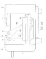
- FIG. 2 is a schematic cross-sectional view showing the internal structure of the cooker body of FIG.
- the cooker body 2 has a box shape with an open front, and includes a heating chamber 5, an upper heater 6, a lower heater 7, a tray 8, and a waveguide 9.
- the heating chamber 5 is a space in which the food SH (to-be-heated material) to be cooked is accommodated, the upper heater 6 and the waveguide 9 are disposed at the upper portion, and the lower heater 7 is disposed at the lower portion.
- the tray 8 is located between the upper heater 6 and the lower heater 7 inside the heating chamber 5 and the food SH to be cooked is placed (placed).
- the upper heater 6 is a tube heater having a circular cross section, and is disposed closer to the front surface (the left side of the heating chamber 5 in FIG. 2) of the heating chamber 5.
- two upper heaters 6 are provided, and the upper heaters 6 and the waveguide 9 are arranged in the opposing direction X in which they face each other.
- the waveguide 9 is disposed closer to the rear surface (the right side of the heating chamber 5 in FIG. 2) of the heating chamber 5 and irradiates microwaves to heat the food SH.
- the upper heater 6 and the waveguide 9 are disposed along the upper surface of the heating chamber 5 and face each other.
- the direction toward the front of the heating chamber 5 may be referred to as the front direction X1
- the direction toward the back of the heating chamber 5 may be referred to as the back direction X2.
- a heater storage portion 10 projecting upward is provided on the upper surface of the heating chamber 5, a heater storage portion 10 projecting upward is provided.
- the lower portion of the heater storage portion 10 is opened, and two upper heaters 6 are stored.
- the auxiliary line L shown in FIG. 2 represents a straight line along the upper surface of the heating chamber 5, and the upper heater 6 is provided at a position higher than the auxiliary line L.
- the radiant heat (first radiant heat FN1) directly transmitted to the food SH generally travels directly under the upper heater 6, and is transmitted to the portion of the food SH near the front of the heating chamber 5. .
- the upper heater 6 is configured to radiate heat in substantially all directions in the periphery, and in addition to radiation heat directly transmitted to the food SH, heat transmitted to the heater storage portion 10 also exists.
- the heater storage portion 10 is formed of a metal plate and reflects the heat emitted from the upper heater 6.
- the heater storage portion 10 has a first reflection portion 11 positioned in the front direction X1 of the upper heater 6 and a second reflection portion 12 positioned in the back surface direction X2 of the upper heater 6.
- the angle (first inclination angle ⁇ 1) formed between the first reflection portion 11 and the upper surface of the heating chamber 5 is about 60 °
- the angle formed between the second reflection portion 12 and the upper surface of the heating chamber 5 (second The inclination angle ⁇ 2) is about 40 °.
- the angle which the 1st reflection part 11 and the 2nd reflection part 12 inclined, and the direction to which the heat which reflected reflected go it demonstrates in detail with FIG. 3 mentioned later.
- two lower heaters 7 are provided, and are arranged at two positions, ie, near the front and back of the heating chamber 5.
- the upper side of the lower heater 7 may be covered with a metal plate.
- the lower heater 7 heats the metal plate by the released heat, and the inside of the heating chamber 5 is heated.
- FIG. 3 is a schematic sectional drawing which shows the structure inside the cooker main-body part of a comparative example.
- the comparative example 100 has a structure substantially the same as that of the first embodiment shown in FIG. 2, and the shape of the heater storage portion 10 is different.
- the angle at which the first reflecting portion 11 and the second reflecting portion 12 are inclined is different, and the angle formed by the first reflecting portion 11 and the upper surface of the heating chamber 5 (third inclination angle ⁇ 3) is approximately
- the angle (a fourth inclination angle ⁇ 4) formed by the second reflecting portion 12 and the upper surface of the heating chamber 5 is approximately 45 °.
- the radiant heat (second radiant heat FN2) directly transmitted to the food SH is transmitted to the portion on the front side of the food SH, as in the first embodiment.
- the heat (third reflected heat HN3) emitted from the upper heater 6 and transmitted to the first reflection portion 11 is reflected by the first reflection portion 11 and travels downward to be transmitted to the portion near the front of the food SH.
- the heat (the fourth reflected heat HN4) emitted from the upper heater 6 and transmitted to the second reflection part 12 is transmitted to the portion near the front of the food SH in the same manner as the third reflected heat HN3.
- the upper heater 6 is disposed to be biased toward the front, heat is less likely to be transmitted to the rear side of the food SH, and burning unevenness becomes large.
- the direction in which the heat is reflected by the first reflecting portion 11 and the second reflecting portion 12 is adjusted to be different from the radiant heat.
- the heat (first reflected heat HN1) emitted from the upper heater 6 and transmitted to the first reflecting portion 11 is reflected by the first reflecting portion 11 and travels downward toward the rear surface direction X2, and the food It is transmitted to the part near the back of SH.
- the heat (second reflected heat HN2) emitted from the upper heater 6 and transmitted to the second reflecting portion 12 proceeds downward while moving in the back surface direction X2 in the same manner as the first reflected heat HN1 to It is transmitted to the part on the back side.
- the direction in which the reflected heat is transmitted can be changed to a desired direction.
- the area directly under the upper heater 6 is heated by the radiant heat directly transmitted from the upper heater 6, and the reflected heat transmitted by the first reflecting portion 11 and the second reflecting portion 12 is the area on the waveguide 9 side.
- the food SH can be heated efficiently.
- the first inclination angle ⁇ 1 and the second inclination angle ⁇ 2 may be appropriately set according to the size of the heating chamber 5 and the like, and it is preferable that the first inclination angle ⁇ 1 be an angle closer to perpendicular than 45 °.
- the second inclination angle ⁇ 2 may be closer to the horizontal than 45 °.
- the upper heater 6 at a position higher than the upper surface of the heating chamber 5 and housed entirely in the heater storage portion 10, the heat diffused to the periphery without being reflected is reduced.
- the heat released from 6 can be used efficiently.
- microwave heating using the waveguide 9 and heater heating using the upper heater 6 or the like can be used in common.
- FIG. 4 is a schematic sectional drawing which shows the structure inside the cooker main-body part in 2nd Embodiment.
- the second embodiment is different from the first embodiment in the shape of the heater storage portion 10 and the position of the lower heater 7.
- the first reflecting portion 11 and the second reflecting portion 12 are formed in a curved shape that is curved so as to protrude in a direction away from the upper heater 6. That is, the first reflection portion 11 is curved to protrude in the front direction X1, and the second reflection portion 12 is curved to protrude in the back direction X2.
- the space in the heater storage portion 10 can be expanded, and the upper heater 6 can be easily stored.
- the heat reflection may be determined based on the main portion. For example, an angle formed by a tangent at the same height as the upper heater 6 (specifically, the center thereof) may be used as a reference, or a straight line connecting the upper end and the lower end of the first reflecting portion 11 (or the second reflecting portion 12) It may be based on the angle formed by
- the heat radiated from the upper heater 6 goes in substantially the same direction as in the first embodiment. That is, the radiant heat (third radiant heat FN3) directly transmitted to the food SH is transmitted to the portion near the front of the food SH. In addition, the heat transmitted to the first reflection portion 11 (fifth reflection heat HN5) and the heat transmitted to the second reflection portion 12 (sixth reflection heat HN6) proceed downward toward the rear surface direction X2, and the rear surface of the food SH It transmits to the part of the side.
- the lower heater 7 is disposed near the rear surface of the heating chamber 5. Therefore, when the lower heater 7 is provided, the heat can be dispersed in a wide range and the uneven baking can be suppressed by bringing the lower heater 7 to the side opposite to the upper heater 6.
- FIG. 5 is a schematic sectional drawing which shows the structure inside the cooker main-body part in 2nd Embodiment.
- the third embodiment is different from the first embodiment in the arrangement of the heater housing portion 10 and the waveguide 9.
- the heater storage portion 10 is provided at two positions, ie, near the front surface of the heating chamber 5 and near the rear surface of the heating chamber 5.
- the waveguide 9 is disposed between the two heater accommodating portions 10 and is disposed substantially at the center of the heating chamber 5 in the opposing direction X.
- the heater storage unit 10 located closer to the front of the heating chamber 5 is called the front side heater storage unit 10a, and the heater storage located closer to the rear surface of the heating chamber 5.
- the portion 10 may be referred to as a rear side heater storage portion 10b.
- the upper heater 6 (the front upper heater 6a and the rear upper heater 6b) is stored in the front heater storage unit 10a and the rear heater storage unit 10b, respectively.
- the structure of the front side heater storage unit 10a is substantially the same as that of the heater storage unit 10 in the first embodiment, and thus the description thereof is omitted.
- the rear surface side heater storage portion 10b has substantially the same structure as the front surface side heater storage portion 10a, and is different from the waveguide 9 in that it is located in the rear surface direction X2.
- the first reflection portion 11 (rear surface first reflection portion 11b) in the rear surface side heater storage portion 10b is located in the rear surface direction X2 of the rear surface side upper heater 6b, and the second reflection in the rear surface side heater storage portion 10b
- the portion 12 (rear surface side second reflection portion 12b) is located in the front direction X1 of the rear surface side upper heater 6b.
- the radiant heat (fourth radiant heat FN4) which is radiated from the front side upper heater 6a and is directly transmitted to the food SH is directed to the lower side and is transmitted to the portion near the front of the food SH.
- the radiant heat (fifth radiant heat FN5) which is radiated from the rear upper surface heater 6b and is directly transmitted to the food SH travels immediately below and is transmitted to the portion near the rear surface of the food SH.
- the heater accommodating portion 10 at two places sandwiching the waveguide 9, it is possible to obtain a structure in which the heat source is dispersed. As a result, heat is radiated from both sides in the opposite direction X, and the entire food SH can be efficiently heated.
Landscapes
- Engineering & Computer Science (AREA)
- Chemical & Material Sciences (AREA)
- Combustion & Propulsion (AREA)
- Mechanical Engineering (AREA)
- General Engineering & Computer Science (AREA)
- Physics & Mathematics (AREA)
- Electromagnetism (AREA)
- Electric Ovens (AREA)
- Constitution Of High-Frequency Heating (AREA)
- Electric Stoves And Ranges (AREA)
Abstract
加熱調理器(1)は、加熱室(5)の上面側に上部ヒータ(6)と導波管(9)とが設けられており、食品(SH)が載置されるトレイ(8)と、上部ヒータ(6)を収納し、下方が開口したヒータ収納部(10)とを備えている。ヒータ収納部(10)は、導波管(9)から遠い側で上部ヒータ(6)に面する第1反射部(11)と、導波管(9)に近い側で上部ヒータ(6)に面する第2反射部(12)とを有している。第1反射部(11)は、加熱室(5)の上面に対して、45°より垂直に近い角度で傾斜している。第2反射部(12)は、加熱室(5)の上面に対して、45°より水平に近い角度で傾斜している。
Description
本発明は、上部ヒータと導波管とが設けられた加熱調理器に関する。
近年、食品を加熱調理する加熱調理器は、様々な形態のものが提案されており、マイクロ波加熱とヒータ加熱との両方の機能を備えたオーブンレンジやトースターレンジが実用化されている。
ところで、マイクロ波加熱をする導波管と、ヒータ加熱をする管ヒータとの両方を加熱調理器に設ける場合、それぞれの配置によって、加熱性能や加熱分布が大きく変わるため、様々な構成が検討されていた(例えば、特許文献1参照)。
特許文献1に記載のヒータ付き高周波加熱調理器は、加熱室天面側にヒータとマイクロ波入射手段とが配置され、加熱室の後壁面を加熱室内側に突出させた突出部が設けられている。上述したヒータ付き高周波加熱調理器では、突出部でマイクロ波を前側に反射させて、マイクロ波による加熱分布の均一化を図っている。
ところで、ヒータと導波管とは、重ねて配置することが困難であるため、ヒータが前後のいずれかに偏った配置となることは避けられない。そのため、上述したヒータ付き高周波加熱調理器では、ヒータの熱の分布が考慮されておらず、ヒータ加熱での加熱分布に偏りが生じてしまう。
本発明は、上記の課題を解決するためになされたものであり、被加熱物全体を効率よく加熱することができる加熱調理器を提供することを目的とする。
本発明に係る加熱調理器は、加熱室の上面側に上部ヒータと導波管とが設けられた加熱調理器であって、前記上部ヒータを収納し、下方が開口したヒータ収納部とを備え、前記加熱室の上面に沿って、前記上部ヒータと前記導波管とが対向する方向を対向方向としたとき、前記ヒータ収納部は、前記対向方向で前記上部ヒータを基準として、前記導波管から遠い側で前記上部ヒータに面する第1反射部と、前記導波管に近い側で前記上部ヒータに面する第2反射部とを有し、前記第1反射部は、前記加熱室の上面に対して、45°より垂直に近い角度で傾斜し、前記第2反射部は、前記加熱室の上面に対して、45°より水平に近い角度で傾斜していることを特徴とする。
本発明に係る加熱調理器では、前記上部ヒータは、少なくとも2つ以上の複数設けられ、前記ヒータ収納部には、前記対向方向に沿って並べられた複数の上部ヒータが収納されている構成としてもよい。
本発明に係る加熱調理器では、前記加熱室の下面側に設けられた下部ヒータを備え、前記下部ヒータは、前記対向方向で前記導波管側寄りに配置されている構成としてもよい。
本発明に係る加熱調理器では、前記ヒータ収納部は、前記加熱室の上面から上方へ突出して設けられ、前記上部ヒータは、前記加熱室の上面より高い位置に設けられている構成としてもよい。
本発明に係る加熱調理器では、前記第1反射部および前記第2反射部は、前記上部ヒータから離間する方向へ突出するように湾曲した曲面状に形成されている構成としてもよい。
本発明に係る加熱調理器では、前記ヒータ収納部は、2つ設けられ、前記導波管は、前記対向方向において、2つのヒータ収納部同士の間に配置されている構成としてもよい。
本発明によると、第1反射部および第2反射部の傾斜を調整することで、反射した熱が伝わる方向を望ましい向きに変えることができる。それによって、上部ヒータから直接伝わる輻射熱で、上部ヒータの直下の領域を加熱し、第1反射部および第2反射部で反射して伝わる反射熱で、導波管側の領域を加熱することができ、被加熱物全体を効率よく加熱することができる。
(第1実施形態)
以下、本発明の第1実施形態に係る加熱調理器について、図面を参照して説明する。
以下、本発明の第1実施形態に係る加熱調理器について、図面を参照して説明する。
図1は、本発明の第1実施形態に係る加熱調理器を示す外観斜視図である。
本発明の第1実施形態に係る加熱調理器1は、調理器本体部2の前面に、前扉3が開閉自在に取り付けられている。調理器本体部2の前面は、加熱調理器1を操作するためのボタンやダイアルなどを有する操作部が取り付けられている。また、前扉3には、調理器本体部2の内部(後述する加熱室5)を視認できるように、透明な材料で形成された覗窓や、ユーザが開閉する際に掴む取っ手が設けられている。
図2は、図1の調理器本体部の内部の構造を示す概略断面図である。
調理器本体部2は、前面が開口した箱形状とされ、加熱室5、上部ヒータ6、下部ヒータ7、トレイ8、および導波管9を備えている。
加熱室5は、加熱調理する食品SH(被加熱物)が収容される空間とされており、上部に上部ヒータ6および導波管9が配置され、下部に下部ヒータ7が配置されている。トレイ8は、加熱室5の内部で、上部ヒータ6と下部ヒータ7との間に位置し、調理する食品SHが配置(載置)される。
上部ヒータ6は、断面が円形とされた管ヒータであって、加熱室5の前面(図2では、加熱室5の左辺)寄りに配置されている。本実施の形態において、上部ヒータ6は、2つ設けられており、上部ヒータ6と導波管9とが対向する対向方向Xで並べられている。導波管9は、加熱室5の後面(図2では、加熱室5の右辺)寄りに配置されており、マイクロ波を照射して食品SHを加熱する。上部ヒータ6と導波管9とは、加熱室5の上面に沿って配置されており、互いに対向している。以下では説明のため、対向方向Xのうち、加熱室5の前面に向かう方向を前面方向X1と呼び、加熱室5の後面に向かう方向を後面方向X2と呼ぶことがある。
加熱室5の上面には、上方へ突出したヒータ収納部10が設けられている。ヒータ収納部10は、下方が開口しており、2つの上部ヒータ6が収納されている。図2に示す補助線Lは、加熱室5の上面に沿った直線を表しており、上部ヒータ6は、補助線Lより高い位置に設けられている。上部ヒータ6から放射された熱のうち、食品SHに直接伝わる輻射熱(第1輻射熱FN1)は、おおむね、上部ヒータ6の直下に向かい、食品SHのうち、加熱室5の前面寄りの部分に伝わる。このように、上部ヒータ6を複数設けることで、高出力で広い範囲を加熱できる。
上部ヒータ6は、周囲の略全方位へ熱を放射する構成とされており、食品SHに直接伝わる輻射熱の他に、ヒータ収納部10に伝わる熱も存在する。ヒータ収納部10は、金属板で形成されており、上部ヒータ6から放出された熱を反射する。ヒータ収納部10は、上部ヒータ6の前面方向X1に位置する第1反射部11と、上部ヒータ6の後面方向X2に位置する第2反射部12とを有している。第1反射部11と加熱室5の上面とがなす角度(第1傾斜角度θ1)は、約60°とされており、第2反射部12と加熱室5の上面とがなす角度(第2傾斜角度θ2)は、約40°とされている。なお、第1反射部11および第2反射部12が傾斜した角度と反射した熱が向かう方向については、後述する図3と併せて、詳細に説明する。
本実施の形態において、下部ヒータ7は、2つ設けられ、加熱室5に対し、前面寄りと後面寄りとの2箇所に配置されている。下部ヒータ7の上方は、金属板で覆われていてもよい。下部ヒータ7は、放出した熱によって金属板を加熱し、加熱室5の内部が加熱される。
次に、従来の構造を示す比較例と、第1実施形態とを比較して、上部ヒータ6から熱が放出される方向を説明する。
図3は、比較例の調理器本体部の内部の構造を示す概略断面図である。
比較例100は、図2に示す第1実施形態と略同様の構造とされており、ヒータ収納部10の形状が異なっている。比較例100では、第1反射部11および第2反射部12が傾斜した角度が異なっており、第1反射部11と加熱室5の上面とがなす角度(第3傾斜角度θ3)は、約45°とされており、第2反射部12と加熱室5の上面とがなす角度(第4傾斜角度θ4)は、約45°とされている。
比較例100において、食品SHに直接伝わる輻射熱(第2輻射熱FN2)は、第1実施形態と同様に、食品SHの前面寄りの部分に伝わる。そして、上部ヒータ6から放出されて、第1反射部11に伝わる熱(第3反射熱HN3)は、第1反射部11に反射されて下方へ向かい、食品SHの前面寄りの部分に伝わる。また、上部ヒータ6から放出されて、第2反射部12に伝わる熱(第4反射熱HN4)は、第3反射熱HN3と同様にして、食品SHの前面寄りの部分に伝わる。
このように、従来の構造では、上部ヒータ6が前面寄りに偏って配置されているため、食品SHの後面側に熱が伝わりにくく、焼きムラが大きくなってしまう。
これに対し、図2に示す第1実施形態では、第1反射部11および第2反射部12で熱を反射する方向が、輻射熱とは異なるように調整している。具体的に、上部ヒータ6から放出されて、第1反射部11に伝わる熱(第1反射熱HN1)は、第1反射部11に反射されて、後面方向X2に向かいながら下方へ進み、食品SHの後面寄りの部分に伝わる。また、上部ヒータ6から放出されて、第2反射部12に伝わる熱(第2反射熱HN2)は、第1反射熱HN1と同様にして、後面方向X2に向かいながら下方へ進み、食品SHの後面寄りの部分に伝わる。このように、第1反射部11および第2反射部12の傾斜を調整することで、反射した熱が伝わる方向を望ましい向きに変えることができる。それによって、上部ヒータ6から直接伝わる輻射熱で、上部ヒータ6の直下の領域を加熱し、第1反射部11および第2反射部12で反射して伝わる反射熱で、導波管9側の領域を加熱することができ、食品SH全体を効率よく加熱することができる。
なお、第1傾斜角度θ1および第2傾斜角度θ2は、加熱室5のサイズ等に応じて、適宜設定すればよく、第1傾斜角度θ1が45°より垂直に近い角度とされていればよく、第2傾斜角度θ2が45°より水平に近い角度とされていればよい。
本実施の形態では、上部ヒータ6を加熱室5の上面より高く、全体がヒータ収納部10に収納される位置に設けることで、反射されずに周囲に拡散される熱を減らして、上部ヒータ6から放出される熱を効率よく利用することができる。
加熱調理器1では、導波管9を用いたマイクロ波加熱と、上部ヒータ6等を用いたヒータ加熱とを兼用することができる。
(第2実施形態)
次に、本発明の第2実施形態に係る加熱調理器について、図面を参照して説明する。なお、第2実施形態では、第1実施形態と略同様の概略構造をしているので、同様の符号を付して、図面および説明を省略する。
次に、本発明の第2実施形態に係る加熱調理器について、図面を参照して説明する。なお、第2実施形態では、第1実施形態と略同様の概略構造をしているので、同様の符号を付して、図面および説明を省略する。
図4は、第2実施形態での調理器本体部の内部の構造を示す概略断面図である。
第2実施形態は、第1実施形態に対して、ヒータ収納部10の形状と下部ヒータ7の位置とが異なっている。具体的に、第1反射部11および第2反射部12は、上部ヒータ6から離間する方向へ突出するように湾曲した曲面状に形成されている。つまり、第1反射部11は、前面方向X1へ突出するように湾曲しており、第2反射部12は、後面方向X2へ突出するように湾曲している。このように、第1反射部11および第2反射部12を湾曲させることで、ヒータ収納部10内の空間を広げて、上部ヒータ6を容易に収納することができる。
第1反射部11および第2反射部12が傾斜している角度を設定する際には、熱の反射において、主体となる部分を基準にして決定すればよい。例えば、上部ヒータ6(詳しくは、その中心)と同じ高さでの接線がなす角度を基準としてもよいし、第1反射部11(または第2反射部12)の上端と下端とを結ぶ直線がなす角度を基準としてもよい。
上部ヒータ6から放射された熱は、第1実施形態と略同様の方向へ向かう。つまり、食品SHに直接伝わる輻射熱(第3輻射熱FN3)は、食品SHの前面寄りの部分に伝わる。また、第1反射部11に伝わる熱(第5反射熱HN5)と第2反射部12に伝わる熱(第6反射熱HN6)とは、後面方向X2に向かいながら下方へ進み、食品SHの後面寄りの部分に伝わる。
第2実施形態において、下部ヒータ7は、加熱室5の後面寄りに配置されている。従って、下部ヒータ7を設ける際、上部ヒータ6と反対の側に寄せることで、熱を広い範囲に分散させ、焼きムラを抑えることができる。
(第3実施形態)
次に、本発明の第3実施形態に係る加熱調理器について、図面を参照して説明する。なお、第3実施形態では、第1実施形態および第2実施形態と略同様の概略構造をしているので、同様の符号を付して、図面および説明を省略する。
次に、本発明の第3実施形態に係る加熱調理器について、図面を参照して説明する。なお、第3実施形態では、第1実施形態および第2実施形態と略同様の概略構造をしているので、同様の符号を付して、図面および説明を省略する。
図5は、第2実施形態での調理器本体部の内部の構造を示す概略断面図である。
第3実施形態は、第1実施形態に対して、ヒータ収納部10と導波管9との配置が異なっている。具体的に、第3実施形態では、ヒータ収納部10が加熱室5の前面寄りと加熱室5の後面寄りとの2箇所に設けられている。導波管9は、2つのヒータ収納部10同士の間に配置され、対向方向Xにおいて、加熱室5の略中央に配置されている。なお、以下では、2つのヒータ収納部10を区別するため、加熱室5の前面寄りに位置するヒータ収納部10を前面側ヒータ収納部10aと呼び、加熱室5の後面寄りに位置するヒータ収納部10を後面側ヒータ収納部10bと呼ぶことがある。
前面側ヒータ収納部10aおよび後面側ヒータ収納部10bには、それぞれ1つずつ上部ヒータ6(前面側上部ヒータ6aおよび後面側上部ヒータ6b)が収納されている。前面側ヒータ収納部10aの構造については、第1実施形態におけるヒータ収納部10と略同様であるので、説明を省略する。後面側ヒータ収納部10bは、前面側ヒータ収納部10aと略同様の構造であって、導波管9に対して、後面方向X2に位置している点が異なる。そのため、後面側ヒータ収納部10bにおける第1反射部11(後面側第1反射部11b)は、後面側上部ヒータ6bの後面方向X2に位置しており、後面側ヒータ収納部10bにおける第2反射部12(後面側第2反射部12b)は、後面側上部ヒータ6bの前面方向X1に位置している。
前面側上部ヒータ6aから放射されて、食品SHに直接伝わる輻射熱(第4輻射熱FN4)は、直下に向かい、食品SHの前面寄りの部分に伝わる。また、後面側上部ヒータ6bから放射されて、食品SHに直接伝わる輻射熱(第5輻射熱FN5)は、直下に向かい、食品SHの後面寄りの部分に伝わる。
前面側ヒータ収納部10aにおける第1反射部11(前面側第1反射部11a)および第2反射部12(前面側第2反射部12a)で反射された熱(第7反射熱HN7および第8反射熱HN8)は、後面方向X2に向かいながら下方へ進み、食品SHのうち、対向方向Xでの略中央の部分に伝わる。また、後面側第1反射部11bおよび後面側第2反射部12bで反射された熱(第9反射熱HN9および第10反射熱HN10)は、前面方向X1に向かいながら下方へ進み、食品SHのうち、対向方向Xでの略中央の部分に伝わる。なお、図5では、第7反射熱HN7ないし第10反射熱HN10が伝わる部分が略同じ部分とされているが、これに限定されず、前面側第1反射部11aなどの傾斜を変えて、熱が伝わる部分を適宜分散させてもよい。
上述したように、導波管9を間に挟む2箇所にヒータ収納部10を設けることで、熱源が分散された構造とすることができる。それによって、対向方向Xの両側から熱が放射されて、食品SH全体を効率よく加熱することができる。
なお、今回開示した実施の形態は全ての点で例示であって、限定的な解釈の根拠となるものではない。従って、本発明の技術的範囲は、上記した実施の形態のみによって解釈されるものではなく、特許請求の範囲の記載に基づいて画定される。また、特許請求の範囲と均等の意味および範囲内での全ての変更が含まれる。
なお、この出願は、日本で2017年10月16日に出願された特願2017-200533号に基づく優先権を請求する。その内容はこれに言及することにより、本出願に組み込まれるものである。また、本明細書に引用された文献は、これに言及することにより、その全部が具体的に組み込まれるものである。
1 加熱調理器
2 調理器本体部
3 前扉
5 加熱室
6 上部ヒータ
7 下部ヒータ
8 トレイ
9 導波管
10 ヒータ収納部
11 第1反射部
12 第2反射部
SH 食品(被加熱物の一例)
X 対向方向
X1 前面方向
X2 後面方向
2 調理器本体部
3 前扉
5 加熱室
6 上部ヒータ
7 下部ヒータ
8 トレイ
9 導波管
10 ヒータ収納部
11 第1反射部
12 第2反射部
SH 食品(被加熱物の一例)
X 対向方向
X1 前面方向
X2 後面方向
Claims (6)
- 加熱室の上面側に上部ヒータと導波管とが設けられた加熱調理器であって、
前記上部ヒータを収納し、下方が開口したヒータ収納部とを備え、
前記加熱室の上面に沿って、前記上部ヒータと前記導波管とが対向する方向を対向方向としたとき、
前記ヒータ収納部は、前記対向方向で前記上部ヒータを基準として、前記導波管から遠い側で前記上部ヒータに面する第1反射部と、前記導波管に近い側で前記上部ヒータに面する第2反射部とを有し、
前記第1反射部は、前記加熱室の上面に対して、45°より垂直に近い角度で傾斜し、
前記第2反射部は、前記加熱室の上面に対して、45°より水平に近い角度で傾斜していること
を特徴とする加熱調理器。 - 請求項1に記載の加熱調理器であって、
前記上部ヒータは、少なくとも2つ以上の複数設けられ、
前記ヒータ収納部には、前記対向方向に沿って並べられた複数の上部ヒータが収納されていること
を特徴とする加熱調理器。 - 請求項1または請求項2に記載の加熱調理器であって、
前記加熱室の下面側に設けられた下部ヒータを備え、
前記下部ヒータは、前記対向方向で前記導波管側寄りに配置されていること
を特徴とする加熱調理器。 - 請求項1または請求項2に記載の加熱調理器であって、
前記ヒータ収納部は、前記加熱室の上面から上方へ突出して設けられ、
前記上部ヒータは、前記加熱室の上面より高い位置に設けられていること
を特徴とする加熱調理器。 - 請求項1または請求項2に記載の加熱調理器であって、
前記第1反射部および前記第2反射部は、前記上部ヒータから離間する方向へ突出するように湾曲した曲面状に形成されていること
を特徴とする加熱調理器。 - 請求項1または請求項2に記載の加熱調理器であって、
前記ヒータ収納部は、2つ設けられ、
前記導波管は、前記対向方向において、2つのヒータ収納部同士の間に配置されていること
を特徴とする加熱調理器。
Priority Applications (1)
| Application Number | Priority Date | Filing Date | Title |
|---|---|---|---|
| JP2019549102A JPWO2019077773A1 (ja) | 2017-10-16 | 2018-02-23 | 加熱調理器 |
Applications Claiming Priority (2)
| Application Number | Priority Date | Filing Date | Title |
|---|---|---|---|
| JP2017-200533 | 2017-10-16 | ||
| JP2017200533 | 2017-10-16 |
Publications (1)
| Publication Number | Publication Date |
|---|---|
| WO2019077773A1 true WO2019077773A1 (ja) | 2019-04-25 |
Family
ID=66172900
Family Applications (1)
| Application Number | Title | Priority Date | Filing Date |
|---|---|---|---|
| PCT/JP2018/006803 Ceased WO2019077773A1 (ja) | 2017-10-16 | 2018-02-23 | 加熱調理器 |
Country Status (2)
| Country | Link |
|---|---|
| JP (1) | JPWO2019077773A1 (ja) |
| WO (1) | WO2019077773A1 (ja) |
Citations (5)
| Publication number | Priority date | Publication date | Assignee | Title |
|---|---|---|---|---|
| JPS5125806Y2 (ja) * | 1971-03-31 | 1976-07-01 | ||
| JPH0320532A (ja) * | 1989-06-19 | 1991-01-29 | Sanyo Electric Co Ltd | 調理器 |
| JPH03110324A (ja) * | 1989-09-22 | 1991-05-10 | Toshiba Corp | 調理器 |
| JP2005009765A (ja) * | 2003-06-19 | 2005-01-13 | Matsushita Electric Ind Co Ltd | 加熱調理器 |
| JP2009264693A (ja) * | 2008-04-28 | 2009-11-12 | Panasonic Corp | 加熱装置 |
-
2018
- 2018-02-23 JP JP2019549102A patent/JPWO2019077773A1/ja active Pending
- 2018-02-23 WO PCT/JP2018/006803 patent/WO2019077773A1/ja not_active Ceased
Patent Citations (5)
| Publication number | Priority date | Publication date | Assignee | Title |
|---|---|---|---|---|
| JPS5125806Y2 (ja) * | 1971-03-31 | 1976-07-01 | ||
| JPH0320532A (ja) * | 1989-06-19 | 1991-01-29 | Sanyo Electric Co Ltd | 調理器 |
| JPH03110324A (ja) * | 1989-09-22 | 1991-05-10 | Toshiba Corp | 調理器 |
| JP2005009765A (ja) * | 2003-06-19 | 2005-01-13 | Matsushita Electric Ind Co Ltd | 加熱調理器 |
| JP2009264693A (ja) * | 2008-04-28 | 2009-11-12 | Panasonic Corp | 加熱装置 |
Also Published As
| Publication number | Publication date |
|---|---|
| JPWO2019077773A1 (ja) | 2020-11-05 |
Similar Documents
| Publication | Publication Date | Title |
|---|---|---|
| KR101617539B1 (ko) | 조리기기 | |
| RU2547883C2 (ru) | Гибридная система для жарки - электрический элемент для жарки | |
| KR20230043090A (ko) | 조리장치 및 그 제어방법 | |
| KR20070050034A (ko) | 가열 조리기 | |
| KR102803121B1 (ko) | 조리 기기 | |
| WO2019077773A1 (ja) | 加熱調理器 | |
| JP4602172B2 (ja) | 加熱調理器 | |
| JP6246040B2 (ja) | 加熱調理器 | |
| CN203517918U (zh) | 加热烹调器 | |
| JP2020094735A (ja) | オーブントースター | |
| JP5683248B2 (ja) | 加熱調理装置 | |
| JP2019020031A (ja) | 加熱調理器 | |
| JP2000205574A (ja) | オ―ブント―スタ― | |
| JPS5918621Y2 (ja) | 電気調理器 | |
| JP5812667B2 (ja) | 加熱調理装置 | |
| JP2011242063A (ja) | 加熱調理器 | |
| KR20110045939A (ko) | 조리기기 | |
| JP7045389B2 (ja) | 加熱調理器 | |
| KR200244742Y1 (ko) | 브로일부의복사열차단구조._ | |
| KR101231322B1 (ko) | 가스 오븐 레인지의 오븐 도어 손잡이 체결구조 | |
| CN120836938A (zh) | 加热烹调器 | |
| KR101545750B1 (ko) | 조리기기 | |
| KR200365633Y1 (ko) | 전기오븐레인지의 오븐부 구조 | |
| KR200365634Y1 (ko) | 전기오븐레인지의 오븐부 구조 | |
| KR200365635Y1 (ko) | 전기오븐레인지의 오븐부 구조 |
Legal Events
| Date | Code | Title | Description |
|---|---|---|---|
| 121 | Ep: the epo has been informed by wipo that ep was designated in this application |
Ref document number: 18868902 Country of ref document: EP Kind code of ref document: A1 |
|
| ENP | Entry into the national phase |
Ref document number: 2019549102 Country of ref document: JP Kind code of ref document: A |
|
| NENP | Non-entry into the national phase |
Ref country code: DE |
|
| 122 | Ep: pct application non-entry in european phase |
Ref document number: 18868902 Country of ref document: EP Kind code of ref document: A1 |