WO2019070022A1 - 蓋体及びこれを備えた飲料容器 - Google Patents
蓋体及びこれを備えた飲料容器 Download PDFInfo
- Publication number
- WO2019070022A1 WO2019070022A1 PCT/JP2018/037189 JP2018037189W WO2019070022A1 WO 2019070022 A1 WO2019070022 A1 WO 2019070022A1 JP 2018037189 W JP2018037189 W JP 2018037189W WO 2019070022 A1 WO2019070022 A1 WO 2019070022A1
- Authority
- WO
- WIPO (PCT)
- Prior art keywords
- lid
- opening
- seal
- seal portion
- beverage container
- Prior art date
- Legal status (The legal status is an assumption and is not a legal conclusion. Google has not performed a legal analysis and makes no representation as to the accuracy of the status listed.)
- Ceased
Links
Images


Classifications
-
- A—HUMAN NECESSITIES
- A47—FURNITURE; DOMESTIC ARTICLES OR APPLIANCES; COFFEE MILLS; SPICE MILLS; SUCTION CLEANERS IN GENERAL
- A47G—HOUSEHOLD OR TABLE EQUIPMENT
- A47G19/00—Table service
- A47G19/12—Vessels or pots for table use
-
- B—PERFORMING OPERATIONS; TRANSPORTING
- B65—CONVEYING; PACKING; STORING; HANDLING THIN OR FILAMENTARY MATERIAL
- B65D—CONTAINERS FOR STORAGE OR TRANSPORT OF ARTICLES OR MATERIALS, e.g. BAGS, BARRELS, BOTTLES, BOXES, CANS, CARTONS, CRATES, DRUMS, JARS, TANKS, HOPPERS, FORWARDING CONTAINERS; ACCESSORIES, CLOSURES, OR FITTINGS THEREFOR; PACKAGING ELEMENTS; PACKAGES
- B65D39/00—Closures arranged within necks or pouring openings or in discharge apertures, e.g. stoppers
- B65D39/08—Threaded or like closure members secured by rotation; Bushes therefor
-
- B—PERFORMING OPERATIONS; TRANSPORTING
- B65—CONVEYING; PACKING; STORING; HANDLING THIN OR FILAMENTARY MATERIAL
- B65D—CONTAINERS FOR STORAGE OR TRANSPORT OF ARTICLES OR MATERIALS, e.g. BAGS, BARRELS, BOTTLES, BOXES, CANS, CARTONS, CRATES, DRUMS, JARS, TANKS, HOPPERS, FORWARDING CONTAINERS; ACCESSORIES, CLOSURES, OR FITTINGS THEREFOR; PACKAGING ELEMENTS; PACKAGES
- B65D47/00—Closures with filling and discharging, or with discharging, devices
- B65D47/04—Closures with discharging devices other than pumps
- B65D47/06—Closures with discharging devices other than pumps with pouring spouts or tubes; with discharge nozzles or passages
- B65D47/08—Closures with discharging devices other than pumps with pouring spouts or tubes; with discharge nozzles or passages having articulated or hinged closures
-
- B—PERFORMING OPERATIONS; TRANSPORTING
- B65—CONVEYING; PACKING; STORING; HANDLING THIN OR FILAMENTARY MATERIAL
- B65D—CONTAINERS FOR STORAGE OR TRANSPORT OF ARTICLES OR MATERIALS, e.g. BAGS, BARRELS, BOTTLES, BOXES, CANS, CARTONS, CRATES, DRUMS, JARS, TANKS, HOPPERS, FORWARDING CONTAINERS; ACCESSORIES, CLOSURES, OR FITTINGS THEREFOR; PACKAGING ELEMENTS; PACKAGES
- B65D53/00—Sealing or packing elements; Sealings formed by liquid or plastics material
- B65D53/02—Collars or rings
-
- A—HUMAN NECESSITIES
- A47—FURNITURE; DOMESTIC ARTICLES OR APPLIANCES; COFFEE MILLS; SPICE MILLS; SUCTION CLEANERS IN GENERAL
- A47J—KITCHEN EQUIPMENT; COFFEE MILLS; SPICE MILLS; APPARATUS FOR MAKING BEVERAGES
- A47J41/00—Thermally-insulated vessels, e.g. flasks, jugs, jars
- A47J41/0005—Thermally-insulated vessels, e.g. flasks, jugs, jars comprising a single opening for filling and dispensing provided with a stopper
- A47J41/0016—Thermally-insulated vessels, e.g. flasks, jugs, jars comprising a single opening for filling and dispensing provided with a stopper the stopper remaining in the opening and clearing a passage way between stopper and vessel for dispensing
-
- A—HUMAN NECESSITIES
- A47—FURNITURE; DOMESTIC ARTICLES OR APPLIANCES; COFFEE MILLS; SPICE MILLS; SUCTION CLEANERS IN GENERAL
- A47J—KITCHEN EQUIPMENT; COFFEE MILLS; SPICE MILLS; APPARATUS FOR MAKING BEVERAGES
- A47J41/00—Thermally-insulated vessels, e.g. flasks, jugs, jars
- A47J41/0005—Thermally-insulated vessels, e.g. flasks, jugs, jars comprising a single opening for filling and dispensing provided with a stopper
- A47J41/0027—Thermally-insulated vessels, e.g. flasks, jugs, jars comprising a single opening for filling and dispensing provided with a stopper the stopper incorporating a dispensing device, i.e. the fluid being dispensed through the stopper
-
- B—PERFORMING OPERATIONS; TRANSPORTING
- B65—CONVEYING; PACKING; STORING; HANDLING THIN OR FILAMENTARY MATERIAL
- B65D—CONTAINERS FOR STORAGE OR TRANSPORT OF ARTICLES OR MATERIALS, e.g. BAGS, BARRELS, BOTTLES, BOXES, CANS, CARTONS, CRATES, DRUMS, JARS, TANKS, HOPPERS, FORWARDING CONTAINERS; ACCESSORIES, CLOSURES, OR FITTINGS THEREFOR; PACKAGING ELEMENTS; PACKAGES
- B65D2251/00—Details relating to container closures
- B65D2251/10—Details of hinged closures
- B65D2251/1016—Means for locking the closure in closed position
- B65D2251/1033—Protuberances and cavities provided on a horizontal flange respectively of the container or base and the closure, and penetrating one into the other, e.g. of the press-button type
-
- B—PERFORMING OPERATIONS; TRANSPORTING
- B65—CONVEYING; PACKING; STORING; HANDLING THIN OR FILAMENTARY MATERIAL
- B65D—CONTAINERS FOR STORAGE OR TRANSPORT OF ARTICLES OR MATERIALS, e.g. BAGS, BARRELS, BOTTLES, BOXES, CANS, CARTONS, CRATES, DRUMS, JARS, TANKS, HOPPERS, FORWARDING CONTAINERS; ACCESSORIES, CLOSURES, OR FITTINGS THEREFOR; PACKAGING ELEMENTS; PACKAGES
- B65D2251/00—Details relating to container closures
- B65D2251/10—Details of hinged closures
- B65D2251/1066—Actuating means
- B65D2251/1075—Levers
Definitions
- the present invention relates to a lid and a beverage container provided with the same.
- Patent Document 1 discloses a beverage container that can be stored in a refrigerator in a horizontal orientation. This beverage container is provided with a lid which can be attached and detached to and from the container body whose upper part is opened.
- the lid is attached together with the O-ring so as to seal the upper opening of the container body, and has a pivotable pouring lid that opens and closes the liquid passage.
- a plug attached with packing is formed on the pouring lid, and the liquid passage can be sealed.
- the horizontal position is made possible by providing locking means for locking the pouring lid in the closed position.
- this problem is not specific to a horizontally-placeable beverage container, but applies to all beverage containers that require a seal such as an O-ring or a packing.
- the present invention aims to provide a lid for a beverage container which is particularly suitable for horizontally-placeable beverage containers and which is easy to handle.
- a lid according to a first aspect of the present invention is a lid attached to a beverage container main body having a peripheral edge defining an opening so as to close the opening, the lid main body, a first seal portion, a second A seal part and a plug are provided.
- the lid body is detachably fixed to the periphery of the opening so as to cover the opening.
- the lid body has an inner surface facing the interior of the beverage container body and a rim defining a spout for pouring the beverage in the beverage container body.
- the first seal portion is integrally formed with the inner side surface, and is configured to be in close contact with the peripheral edge portion of the opening to seal a gap between the peripheral edge portion of the opening and the lid main body.
- the second seal portion is integrally formed with the first seal portion by the same material as the first seal portion, and is integrally formed with the peripheral portion defining the spout.
- the plug body is movably disposed between a closed position in which the spout is sealed in close contact with the second seal portion and an open position in which the inside and the outside of the beverage container main body are communicated with each other through the spout. .
- the lid according to a second aspect of the present invention is the lid according to the first aspect, wherein the first seal portion and the second seal portion are formed of materials different from the lid main body.
- a lid according to a third aspect of the present invention is the lid according to the first aspect or the second aspect, wherein the lid main body and the plug are made of resin, and the first seal portion and the second The seal is made of an elastomer. Therefore, the lid main body can be configured to be light in weight and hard to be deformed, and the workability at the time of attachment / detachment to the container main body and opening / closing of the spout can be secured. At the same time, due to the elasticity of the elastomer, the first seal portion can be in close contact with the peripheral edge portion of the opening of the beverage container main body, and the second seal portion can be in close contact with the stopper, and sealing can be ensured.
- a beverage container according to a fourth aspect of the present invention includes a beverage container main body having a peripheral edge defining an opening, and a lid according to any one of the first to third aspects attached to the beverage container main body.
- the first seal portion plays the role of packing that seals the gap between the peripheral portion of the opening of the beverage container body and the lid body
- the second seal portion is between the spout and the plug body Plays the role of packing that seals the gap between
- the first seal portion and the second seal portion are integrally formed of the same material.
- the first seal portion is integrally formed with the inner side surface of the lid
- the second seal portion is integrally formed with the peripheral portion of the spout. Therefore, the number of parts does not increase, there is no risk of losing the packing, and the handling at the time of the cleaning operation and the assembling operation is easy. Furthermore, there is no gap in which water, dirt and the like can enter between the first seal portion and the inner side surface of the lid and between the second seal portion and the peripheral portion of the spout, so cleaning is easy.
- the external appearance side view of the beverage container concerning one embodiment of the present invention.
- A Front view of the beverage container main body.
- B Side view of the beverage container body. The side view which saw through the inside of a lid. The top view which saw through the inside of a lid. The bottom view of a lid.
- A Bottom view of seal part.
- B The II sectional drawing of (A). The expanded sectional view of opening vicinity which is a pouring spout.
- A The side view which saw through the inside of the seesaw member.
- B Bottom view of the seesaw member.
- A The top view of a locking member.
- B Left side view of locking member. Rear view of the lid.
- A Explanatory drawing of a closed state.
- B An explanatory view of an open state.
- FIG. 1 is an external side view of a beverage container 100 according to the present embodiment
- FIG. 2 is an external plan view.
- the beverage container 100 is a beverage container called a water pitcher, a cold water cylinder or the like, and is used to store beverages such as tea and water.
- the beverage container 100 can be stored in a vacant space in the refrigerator in various postures, such as vertically or horizontally, effectively utilizing the limited space in the refrigerator.
- the bottom surface 201 faces vertically downward and the spout 15 faces vertically upward
- the side surface 202 c or 202 d faces vertically downward, the spout It is a posture where 15 points to the side.
- a beverage container 100 has a container body 200 and a lid 1.
- the container body 200 is a container whose top is open.
- the lid 1 is detachably attached to the container body 200 so as to seal the opening of the container body 100.
- the vertical direction and the front-rear direction are defined as shown in FIG.
- the direction from the back to the front of the paper is the left, and the direction from the front to the back is the right.
- description of other drawings will be made based on this.
- the container main body 200 is a container whose top is open so as to be able to accommodate a beverage, and a bottom surface 201 and a cylindrical side surface surrounding the bottom surface 201. And a unit 202.
- FIG. 3A is a view of the container body 200 as viewed from the front
- FIG. 3B is a view of the container body 200 as viewed from the left.
- the material of each part of the container main body 200 is not specifically limited, For example, it can be made hard resin.
- the container main body 200 it is desirable to be formed transparent so that an inside can be visually recognized.
- the bottom portion 201 is substantially rectangular.
- the side surface section 202 is a side surface section rising upward while gently sloping from the left and right long side sections 202 a and 202 b standing straight upward from the front and rear short sides of the bottom surface section 201. 202c and 202d. That is, the side portions 202a to 202d are formed substantially in a planar shape. Therefore, the container main body 200 stably stands up with the bottom surface portion 201 in the vertically downward state, and is stable even in the state where the left and right side surface portions 202c and 202d are in the vertically downward position.
- a cylindrical portion 203 in which a thread groove 203a is formed on the outer peripheral surface is continuous.
- the cylindrical portion 203 is a peripheral portion that defines the upper opening S1 of the container body 200.
- the cylindrical portion 203 may be referred to as the peripheral portion 203.
- the beverage stored in the beverage container 100 is poured through the upper opening S1 and accommodated in the container body 200.
- the screw groove 203 a is screwed with a screw groove 12 a of the lid 1 described later to enable the lid 1 to be attached to and detached from the container main body 200.
- FIG. 4 is a side view of the lid 1.
- the lid 1 is configured to cover the upper opening S1 of the container main body 200, and includes a lid main body 11 and a seal portion 20 made of an elastomer described later.
- the lid main body 11 of the present embodiment is made of hard resin such as polypropylene or ABS resin.
- the lid body 11 has a cylindrical portion 12 having a thread groove 12 a on the inner peripheral surface, and a disk-shaped upper surface portion 13 continuous with the upper end edge of the cylindrical portion 12. Then, the lid 1 can be attached to the container main body 200 by rotating the lid 1 while aligning the screw groove 12 a with the screw groove 203 a. Further, the lower surface 14 of the upper surface portion 13 faces the inside of the container main body 200 through the upper opening S1.
- the lower surface 14 is hereinafter referred to as the inner surface 14.
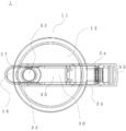
- FIG. 5 is a plan view seen through the inside of the lid 1.
- a circular opening S2 is formed in the substantially disk-shaped upper surface portion 13 at a position radially outward from the center thereof.
- the opening S2 is an opening for communicating the inside and the outside of the container body 200 in a state where the lid 1 is attached to the container body 200, and serves as a spout for pouring the beverage in the container body 200 into a cup or the like.
- the opening S2 is defined by a peripheral portion 60 integrally formed with a second seal portion 22 described later.
- the upper surface 22c of the 2nd seal part 22 comprises the valve seat 22c mentioned later.
- the lid body 11 includes a pair of left and right plate-like wall portions 2 a and 2 b extending in the front-rear direction, which stand on the upper surface portion 13.
- the wall portions 2a and 2b pass the center of the upper surface portion 13 and have a symmetrical structure with respect to a plane extending in the front-rear direction and the up-down direction.
- the opening S2 described above is disposed between the walls 2a and 2b.
- a seesaw member 30 and a locking member 40 which will be described later, are accommodated in the space between the wall portions 2a and 2b.
- the lock member 40 is an operation unit that the user operates to swing the seesaw member 30. Then, when the lock member 40 is operated and the seesaw member 30 swings, the valve body 31 (plug) coupled near the front end portion 37 of the seesaw member 30 swings so as to open and close the opening S2.
- the lid body 11, the seal portion 20, the seesaw member 30, the lock member 40 and the valve body 31 constitute a part of the lid 1.
- the lid body 11 is provided with a beverage spout portion 15 continuous to the front portions of the wall portions 2a and 2b in the vicinity of the opening S2.
- the spout portion 15 forms a funnel-shaped slope that is inclined so as to extend upward from the upper surface portion 13, and the space defined by the slope communicates with the opening S 2. ing. Therefore, when the beverage container 100 is inclined, the beverage flows from the container body 200 to the cup or the like along the slope of the spout portion 15.
- the front end 37 of the seesaw member 30 covers the entire spout 15 when the opening S2 is sealed, and opens the spout 15 when the opening S2 is open. Accordingly, dust and the like can be prevented from entering the spout portion 15 and becoming dirty.
- the lid body 11 is provided with a handle portion 50.
- the handle 50 is continuous downward from the rear portion on the opposite side of the spout 15 in the walls 2 a and 2 b.
- the handle part 50 is an annular member which has a through-hole in the left-right direction as shown in FIG. 1 etc., and a user can hold by hand. The user can use the handle 50 when pouring a beverage through the spout 15, carrying the beverage container 100, or the like.
- the seal portion 20 is made of an elastomer as described above, and functions as a packing that maintains the liquid tightness of the beverage container 100 by being elastically deformed.
- the seal portion 20 In a state where the lid 1 is attached to the container main body 200, the seal portion 20 is in close contact with the peripheral edge portion 203 of the upper opening S1, and seals the gap between the container main body 200 and the lid main body 11. Further, the seal portion 20 is in close contact with a valve body 31 described later, and seals the opening S2 which is a spout of the beverage.
- the former sealability is achieved by the first seal portion 21 included in the seal portion 20, and the latter sealability is achieved by the second seal portion 22 included in the seal portion 20.
- the first seal portion 21 and the second seal portion 22, that is, the entire seal portion 20 are integrally formed of the same material.
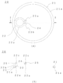
- FIG. 6 is a bottom view of the lid 1 and shows the lid 1 viewed from the side of the inner surface 14.
- the left and right two walls 16a and 16b are formed on the inner side surface 14.
- the walls 16a and 16b respectively extend radially inward from the vicinity of the spout portion 15, and further extend semicircularly around the opening S2 toward the handle portion 50, and have a U-turn at the end .
- the walls 16a and 16b rise straight from the inner surface 14 toward the lower container body 200 side.
- the second seal portion 22 has a substantially cylindrical shape, and is integrally formed with the walls 16a and 16b and the peripheral portion 60 (see FIG. 8) of the opening S2. As shown in FIG.
- the second seal portion 22 extends radially outward and downward along the peripheral portion 60 from the portion on the spout portion 15 side, and then continues to the first seal portion 21.
- the walls 16 a and 16 b and the peripheral portion 60 are all part of the lid body 11 and made of hard resin as described above, and are different from the second seal portion 22.
- the second seal portion 22 is integrally formed in a non-removable manner with respect to these portions of the lid main body 11, and no gap is formed between the two.
- the first seal portion 21 closely contacts the peripheral edge portion 203 of the upper opening S1 and seals the upper opening S1. Therefore, the first seal portion 21 is generally ring-shaped, and has an outer diameter substantially equal to the peripheral edge portion 203 of the upper opening S1.
- the first seal portion 21 extends along the circumferential direction in the vicinity of the outer peripheral edge of the inner side surface 14 and is formed integrally with the inner side surface 14.
- the upper surface portion 13 having the inner side surface 14 is a part of the lid main body 11 and is made of hard resin as described above, and is different from the first seal portion 21.
- the first seal portion 21 is integrally configured so as not to be removable from the upper surface portion 13 of the lid main body 11, and no gap is formed between the first seal portion 21 and the inner side surface 14.
- the seal portion 20 is integrally formed with the lid body 11 as a part of the lid 1. Therefore, water, dirt, and the like do not enter between the seal portion 20 and the lid body 11, which facilitates cleaning.
- FIG. 7 (A) is a bottom view of the seal portion 20, and FIG. 7 (B) is a cross-sectional view taken along the line II of FIG. 7 (A).
- the second seal portion 22 is formed so as to extend radially inward continuously from the inner peripheral portion of the first seal portion 21.
- the surface facing the inside of the container body 200 is referred to as the lower surface of the seal portion 20, and the lower surface of the first seal portion 21 is 21a and the lower surface of the second seal portion 22.
- Each is referred to as 22a.
- the lower surface 21a and the lower surface 22a do not coincide in vertical position, and the lower surface 22a is at a position higher in the vertical direction than the lower surface 21a.
- Two arms 23a and 23b extend in a shape corresponding to the walls 16a and 16b at a position approximately 180 ° away from the portion of the second seal 22 which is continuous with the first seal 21. .
- a notch 24 is formed in the vertical direction between the arm 23a and the arm 23b, and the lower surface 22a at the position of the notch 24 is higher in the vertical direction than the lower surface 22a in the other parts. is there.
- the thickness of the second seal portion 22 is thinner at the portion of the notch portion 24 than at other portions.
- the thickness of the first seal portion 21 is substantially constant throughout the circumferential direction.
- the second seal portion 22 has a substantially cylindrical shape, and as shown in FIG. 7B, a recess 25 is formed on the outer peripheral surface 22b, and has an upper surface 22c opposite to the lower surface 22a.
- the upper surface 22c plays a role as a valve seat of a valve body 31 described later.
- the upper surface 22c may be referred to as a valve seat 22c.
- the recess 25 is formed over the entire circumferential direction.
- the thickness of the second seal portion 22 is substantially constant in the circumferential direction except for the portion of the notch 24.
- the lower surface 22 a of the second seal portion 22 is formed so as to extend radially inward from the vicinity of the upper surface of the first seal portion 21.
- FIG. 8 shows details of the cross section in the vicinity of the opening S2 of the lid body 11 forming the spout.
- the lid body 11 is shown by a solid line, and the seal portion 20 is shown by a broken line.
- the cylindrical part 203 of the container main body 200 is shown with a dashed-dotted line as a reference.
- the second seal portion 22 is formed to be in close contact with the peripheral portion 60 while receiving the convex portion 62 of the peripheral portion 60 in the recess 25.
- the pouring spout of a drink is formed by the opening S2 prescribed
- the spout is a space one size smaller than the opening S2. From this viewpoint, it can be said that the opening S (spout) is defined by the second seal portion 22.
- the upper surface of the upper surface portion 13 and the valve seat 22 c of the second seal portion 22 are formed flush with each other.
- the inner side surface 14 of the lid main body 11 is formed flush with the lower surface 22 a of the notch portion 24 of the second seal portion 22.
- the lower surface 22a other than the notch 24 is formed flush with the lower ends of the walls 16a and 16b.
- a first seal portion is formed on the upper end of the cylindrical portion 203 of the container body 200.
- the lower surface 21a of 21 contacts.
- the upper end of the cylindrical portion 203 bites into the lower surface 21a of the first seal portion 21. That is, the lower surface 21a of the first seal portion 21 is in close contact with the upper end of the cylindrical portion 203, and the upper opening S1 of the container body 200 is kept liquid tight.
- the seal portion 20 formed in the lid 1 can play a role of packing that seals not only the upper opening S1 of the container body 200 but also the opening S2 formed in the lid 1 .
- a lock mechanism capable of locking the closed state and the open state of the opening S2 by opening and closing the opening S2 which is the pouring spout will be described.
- It is a rockable seesaw member 30 which constitutes a part of the lid 1 and which opens and closes the opening S2.
- the seesaw member 30 is disposed so as to be sandwiched between the wall portions 2a and 2b in the left-right direction.
- the seesaw member 30 of the present embodiment is made of hard resin such as polypropylene or ABS resin as the lid main body 11 is.
- the seesaw member 30 has a substantially plate-like main body 30 a that extends in the front-rear direction so as to cover from the tip of the spout 15 to the upper side of the handle 50.
- a cylindrical valve body 31 is attached near the front end portion 37 of the main body portion 30a.
- the valve body 31 is disposed so that the central axis extends in the vertical direction on the lower surface of the main body 30a.
- the valve body 31 is integrally formed with the main body portion 30a.
- the valve body 31 opens and closes the opening S2 as the seesaw member 30 swings. In the state of FIG. 4 and FIG.
- the main body portion 30 a is positioned substantially horizontally, and the lower end of the valve body 31 is in close contact with the upper surface 22 c of the second seal portion 22 to seal the opening S 2.
- a state in which the opening S2 is sealed by the valve body 31 is referred to as a closed state, and a state in which the opening S2 is opened is referred to as an open state.
- FIG. 9A is a side view seen through the inside of the seesaw member 30, and FIG. 9B is a bottom view of the seesaw member 30.
- the seesaw member 30 has a pair of left and right pillars 34a and 34b extending in the left and right direction at the rear end 33 of the main body 30a.
- the central axes of the columns 34a and 34b coincide.
- the right column body 34a has a shape in which a portion of a cylinder is cut away as viewed in the left-right direction, and the cut portion forms a recessed portion 35a which is recessed in an arc shape.
- the seesaw member 30 has a symmetrical shape as a whole.
- the left column body 34b also has a symmetrical shape with the right column body 34a, and similarly has a recess 35b.
- the concave portions 35a and 35b are configured to receive the tips of convex portions 43a and 43b of the lock member 40 described later (see FIG. 12A).
- a pressed portion 36 curved in a curved shape centering on the pillars 34a and 34b in a side view is formed.
- the seesaw member 30 has a hook-like claw 32 extending downward from the main body 30 a in the vicinity of the center in the front-rear direction as a fulcrum of swinging.
- the claw portion 32 is configured to engage with a spherical claw portion 17 (see FIG. 4) extending upward from the base portion 17a rising from the upper surface portion 13 between the wall portions 2a and 2b.
- the claws 32 can slide around the claws 17 along the surface of the claws 17.
- the seesaw member 30 can swing as the claw portion 32 slides on the surface of the claw portion 17 while using the point where the claw portion 32 engages with the claw portion 17 as a fulcrum.
- the rear end 33 of the seesaw member 30 is supported by a lock member 40.
- the lock member 40 is a member operated by the user to swing the seesaw member 30. As shown in FIG. 1, in the appearance of the beverage container 100, the locking member 40 projects from the rear of the handle 50 and the upper wall portions 2a and 2b only a part of the lever 41 included in the locking member 40. Configured to The positional relationship between the lever portion 41 and the handle portion 50 is such that when the user grips the handle portion 50, the user can just apply the thumb.
- the lock member 40 according to the present embodiment is made of hard resin such as polypropylene or ABS resin as the lid body 11 is.
- FIG. 10A is a plan view of the lock member 40
- FIG. 10B is a left side view of the lock member 40
- the lock member 40 has a laterally symmetrical shape as a whole, and has a side wall 40 a rising upward from the right end of the lever portion 41 and a side wall 40 b rising upward from the left end of the lever portion 41.
- convex portions 43a and 43b having arc-shaped tip portions in side view are respectively formed, and these tip portions are respectively received by the recesses 35a and 35b of the seesaw member 30 described above.
- a space T1 is formed in front of the lever portion 41 between the side walls 40a and 40b.
- the space between the side walls 40a and 40b is wider than the width of the rear end 33 of the seesaw member 30 in the left-right direction, and the rear end 33 of the seesaw member 30 enters the space T1 as described later (FIG. B) see).
- convex portions 45a and 45b are formed at a distance rearward from the above-described convex portions 43a and 43b constituting the front portions of the side walls 40a and 40b, respectively.
- These convex portions 43a, 43b, 45a and 45b all project upward in the closed state of the opening S2 as shown in FIG. 12 (A).
- the groove part 42a which has a bottom part 46a as shown in FIG. 10 is formed.
- a groove 42b having a bottom 46b is formed between the left side projections 43b and 45b.
- the upper end of the lever portion 41 functions as a pressing portion 47 that holds the held portion 36 of the seesaw member 30 in the open state of the opening S2 as shown in FIG. 12 (B).
- the locking member 40 has a cylindrical shaft 44 between the side walls 40a and 40b, more specifically between the projections 43a and 43b.
- the shaft 44 is received by the bearing 51 formed between the wall 2 a and the wall 2 b at the upper end of the handle 50.
- the bearing portion 51 has a shape obtained by cutting out the upper portion of a cylinder having a central axis extending in the left-right direction, and the shaft portion 44 is inserted into the internal space defined by the bearing portion 51 via the cutout portion. Ru.
- the lock member 40 can swing the shaft portion 44 engaged with the bearing portion 51 as a rotation shaft by pushing up or down the lever portion 41.
- the direction in which the lever portion 41 is pushed up is the direction in which the valve body 31 separates from the valve seat 22c (clockwise direction in FIG. 12).
- the direction in which the lever portion 41 is pushed down is the direction in which the valve body 31 approaches the valve seat 22c (the counterclockwise direction in FIG. 12).
- FIG. 11 is a rear view of the lid 1 in the closed state.
- the lock member 40 is disposed below the seesaw member 30 so as to be sandwiched between the seesaw member 30 and the wall portions 2a and 2b in the left-right direction.
- the lever portion 41 is formed with a plurality of notches in the left-right direction, so that the user's finger does not slip easily, and the user can easily transmit the force to the lock member 40.
- FIG. 12A is a side view seen through the water stop mechanism in the closed state of the opening S2.
- the main body portion 30 a of the seesaw member 30 is horizontally supported from below by the claw portion 17 and the convex portions 43 a and 43 b of the lock member 40.
- the convex portions 43 a and 43 b support the rear end portion 33 of the seesaw member 30 and engage with the concave portions 35 a and 35 b of the seesaw member 30 to lock the rear end portion 33.
- This lock is not released unless an external force that causes elastic deformation of the pillars 34a and 34b and the protrusions 43a and 43b via the lever portion 41 is exerted.
- valve body 31 can be kept in close contact with the valve seat 22c to maintain the liquid tight state of the opening S2. it can.
- FIG. 12 (B) is a side view seen through the water stopping mechanism in a state of being locked in the open state.
- the user holds the handle 50 with one hand and applies a force to push the lever 41 upward with the thumb of the hand.
- the lock member 40 starts rotating with the shaft portion 44 as a rotation shaft, and the engagement between the concave portions 35a and 35b and the convex portions 43a and 43b is released, and the rear end 33 is downward and the valve 31 is upward.
- the seesaw member 30 starts swinging in the direction of When the lever portion 41 is further pushed up, the rear end portion 33 of the seesaw member 30 enters the space T1 between the side walls 40a and 40b of the lock member 40.
- the pillars 34 a and 34 b of the seesaw member 30 enter the grooves 42 a and 42 b of the lock member 40, respectively.
- the lever portion 41 is pushed up to a position where the pressing portion 47 of the locking member 40 holds the pressed portion 36 of the seesaw member 30, the pillars 34a and 34b engage with the deepest bottom portions 46a and 46b of the grooves 42a and 42b. And locked.
- the seesaw member 30 can be held in the state in which the opening S2 is open.
- the inside of the container body 200 is kept liquid-tight by the sealing mechanism and the locking mechanism described above. Therefore, even if the beverage container 100 is placed horizontally, the beverage in the container body 200 does not leak to the outside. Therefore, even if there is no space for placing the beverage container 100 vertically in the refrigerator, the beverage container 100 can be housed in the refrigerator in the horizontal position.
- the width of the lid 1 in the left-right direction is within the range of the width of the container body 200 in the left-right direction. Therefore, by orienting the generally planar side portions 202c and 202d vertically downward, the lateral sides can be stably placed.
- the user When the beverage is taken out of the beverage container 100, the user first grips the handle 50 and pushes up the lever 41 projecting backward from above the handle 50 with the thumb of the hand. Then, it is confirmed that the pillars 34a and 34b of the seesaw member 30 are locked in the grooves 42a and 42b of the lock member 40 respectively, and the thumb is released from the lever portion 41. Then, while holding the handle portion 50, the beverage container 100 is inclined, and the beverage is poured into a cup or the like through the spout portion 15. After pouring, while holding the handle portion 50, a downward force is applied to the lever portion 41 with the thumb of the hand to release the locked state.
- the user rotates the lid 1 to remove the lid 1 and the container body 200.
- the lid main body 11 and the seal portion 20 can be collectively and easily cleaned from the side of the inner side surface 14 of the lid 1.
- the container main body 200 can directly wash the inside of the container main body 200 by inserting a sponge with a hand or a handle into the container main body 200 through the relatively wide upper opening S1.
- the first seal portion 21 plays the role of packing that seals the upper opening S1
- the second seal portion 22 plays the role of the packing that seals the opening S2.
- the first seal portion 21 and the second seal portion 22 are integrally formed of the same material, and are also integrally formed of the lid main body 11 which is a different material. Therefore, it is not necessary to provide a packing for sealing the upper opening S1 and a packing for sealing the opening S2 as separate parts of the lid main body 11, and it takes time and effort to set the packing when attaching the lid 1 to the container main body 200. Can be saved. In addition, there is no gap in which water, dirt, or the like enters between the first seal portion 21 and the second seal portion 22 and the lid body 11.
- the lid 1 and the seal portion 20 can be cleaned at the same time during cleaning, the cleaning operation is simplified, and it is free from the trouble of removing and cleaning the packing one by one. Furthermore, the risk of losing the removed packing during cleaning is eliminated. Further, since the first seal portion 21 and the second seal portion 22 are formed of the same material and are continuous with each other, the material can be simultaneously poured into a molding die or the like in the molding step of the seal portion 20. , The molding process is simplified.
- the lever portion 41 is disposed below the rear end portion 33 of the seesaw member 30, and the valve body 31 is disposed on the front end portion 37 side with respect to the fulcrum portion of the seesaw member 30.
- the user intuitively rotates the seesaw member 30 in the direction in which the valve body 31 is pushed up from the valve seat 22c, Recall to depress the lever portion 41.
- the spout is opened by operating the lever portion 41 in the direction opposite to the operation direction that is intuitively recalled in this manner. Therefore, it is easy to prompt the user to act consciously and to prevent the user from accidentally opening the spout.
- the cover 1 of the said embodiment becomes possible [transversely placing of the drink container 100] by providing the above-mentioned seal part 20 and the locking mechanism which can lock the sealed state of a pouring spout.
- the shapes of the arm portions 23a and 23b of the second seal portion 22 are not limited to the shapes as described above, and can be various shapes. Further, the second seal portion 22 may be formed in a ring shape continuous with the first seal portion 21 without forming the arm portion.
- lid 1 concerning the above-mentioned embodiment was used for drink container 100 which can lay horizontally
- a beverage container in which lid 1 is used is not restricted to the above-mentioned thing.
- the concave portions 35a and 35b are formed in the pillars 34a and 34b, and the tips of the convex portions 43a and 43b are respectively received by these, but the convex portions are formed in the pillars 34a and 34b Alternatively, they may be configured to be received in the recesses formed at the tips of the protrusions 43a and 43b, respectively.
- lid 11 lid main body 12 cylindrical portion 12a screw portion 13 upper surface portion 14 inner side surface 15 spout portion 16a, 16b wall 20 seal portion 21 first seal portion 21a lower surface 22 second seal portion 22a lower surface 22b outer peripheral surface 22c valve seat ( Upper surface) 23a, 23b Arm 24 Notched part 25 Concave 30 Seesaw member 31 Valve body (plug) 33 Rear end (first end) 37 Front end (second end) 40 lock member 41 lever portion 50 handle portion 100 beverage container 200 container main body 202a-d side surface portion 203 cylindrical portion (peripheral portion) 203a Threaded part S1 Upper opening S2 opening (spout)
Landscapes
- Engineering & Computer Science (AREA)
- Mechanical Engineering (AREA)
- Closures For Containers (AREA)
Priority Applications (4)
| Application Number | Priority Date | Filing Date | Title |
|---|---|---|---|
| JP2019547011A JP6945880B2 (ja) | 2017-10-06 | 2018-10-04 | 蓋体及びこれを備えた飲料容器 |
| CN201880064840.0A CN111343888B (zh) | 2017-10-06 | 2018-10-04 | 盖体及具备其的饮用物容器 |
| US16/753,419 US11517131B2 (en) | 2017-10-06 | 2018-10-04 | Cover, and beverage container comprising same |
| EP18864005.6A EP3673771A1 (en) | 2017-10-06 | 2018-10-04 | Cover, and beverage container comprising same |
Applications Claiming Priority (2)
| Application Number | Priority Date | Filing Date | Title |
|---|---|---|---|
| JP2017196078 | 2017-10-06 | ||
| JP2017-196078 | 2017-10-06 |
Publications (1)
| Publication Number | Publication Date |
|---|---|
| WO2019070022A1 true WO2019070022A1 (ja) | 2019-04-11 |
Family
ID=65995082
Family Applications (1)
| Application Number | Title | Priority Date | Filing Date |
|---|---|---|---|
| PCT/JP2018/037189 Ceased WO2019070022A1 (ja) | 2017-10-06 | 2018-10-04 | 蓋体及びこれを備えた飲料容器 |
Country Status (5)
| Country | Link |
|---|---|
| US (1) | US11517131B2 (https=) |
| EP (1) | EP3673771A1 (https=) |
| JP (2) | JP6945880B2 (https=) |
| CN (1) | CN111343888B (https=) |
| WO (1) | WO2019070022A1 (https=) |
Cited By (2)
| Publication number | Priority date | Publication date | Assignee | Title |
|---|---|---|---|---|
| JP2023057493A (ja) * | 2021-10-11 | 2023-04-21 | 岩崎工業株式会社 | 蓋体 |
| JP2024009626A (ja) * | 2022-07-11 | 2024-01-23 | タイガー魔法瓶株式会社 | 調理器 |
Families Citing this family (1)
| Publication number | Priority date | Publication date | Assignee | Title |
|---|---|---|---|---|
| JP6945880B2 (ja) * | 2017-10-06 | 2021-10-06 | 岩崎工業株式会社 | 蓋体及びこれを備えた飲料容器 |
Citations (3)
| Publication number | Priority date | Publication date | Assignee | Title |
|---|---|---|---|---|
| JP2009132421A (ja) | 2007-11-30 | 2009-06-18 | Asuberu Kk | 冷水筒 |
| US20140175042A1 (en) * | 2012-05-30 | 2014-06-26 | Thermos L.L.C. | Beverage bottle and lid with back button release |
| US20170174400A1 (en) * | 2015-12-21 | 2017-06-22 | Handi-Craft Company | Valve assembly for a drinking cup and a drinking cup having a valve assembly |
Family Cites Families (34)
| Publication number | Priority date | Publication date | Assignee | Title |
|---|---|---|---|---|
| US486298A (en) * | 1892-11-15 | Valved cap or stopper for bottles | ||
| US2197352A (en) * | 1938-01-17 | 1940-04-16 | Terkel Abraham | Vented valve |
| US3154227A (en) * | 1961-09-25 | 1964-10-27 | Farmer Bros Co | Decanter with pouring spout and seal |
| US3330449A (en) * | 1965-08-25 | 1967-07-11 | Bloomfield Ind Inc | Decanter with detachable spout |
| US3655102A (en) * | 1969-12-15 | 1972-04-11 | James G Moran | Bottle cap and cover |
| US3632025A (en) * | 1970-09-04 | 1972-01-04 | Bloomfield Ind Inc | Decanter lid assembly |
| US3744662A (en) * | 1971-11-23 | 1973-07-10 | Nat Can Corp | Opening device with non-detachable tab |
| US4090648A (en) * | 1976-04-09 | 1978-05-23 | Bloomfield Industries, A Division Of Beatrice Foods Co. | Decanter and molded interlocking handle |
| CH597047A5 (https=) * | 1976-07-15 | 1978-03-31 | Anders Ruben Rausing | |
| JPS602637U (ja) | 1983-06-18 | 1985-01-10 | 東洋製罐株式会社 | 注出容器 |
| JPH0628460Y2 (ja) | 1986-10-03 | 1994-08-03 | ライオン株式会社 | キヤツプ体 |
| US4775065A (en) * | 1986-11-06 | 1988-10-04 | Shastal Eugene D | Tamper-resistant dispensing closure |
| US4736858A (en) * | 1986-11-06 | 1988-04-12 | Shastal Eugene D | Selectively closable container closure |
| US4932544A (en) * | 1987-12-08 | 1990-06-12 | Gdalia Glazer | Bottle holder |
| DE29504343U1 (de) * | 1995-03-14 | 1996-07-18 | Emsa-Werke Wulf GmbH & Co, 48282 Emsdetten | Kanne für Flüssigkeiten |
| FR2752818B1 (fr) * | 1996-08-29 | 1998-10-16 | Oreal | Capsule articulee a element de liaison ameliore |
| US6269984B1 (en) * | 1999-11-10 | 2001-08-07 | The Thermos Company | Dispensing stopper for a bottle |
| JP2002165709A (ja) * | 2000-11-30 | 2002-06-11 | Nippon Sanso Corp | 飲料容器の栓体 |
| US6702137B1 (en) * | 2001-04-04 | 2004-03-09 | Nippon Sanso Corp. | Plug structure for liquid container |
| JP4925165B2 (ja) | 2006-01-31 | 2012-04-25 | 株式会社吉野工業所 | 蓋付き高気密容器 |
| US7735698B2 (en) * | 2007-08-31 | 2010-06-15 | Shin-Shuoh Lin | No-drip carafe |
| CN202086156U (zh) * | 2011-06-02 | 2011-12-28 | 吕乐德 | 一种密封冷水壶 |
| JP2014525880A (ja) * | 2011-08-12 | 2014-10-02 | デサロジョス タマリット プラザ エセエレ | キャップ |
| JP5573890B2 (ja) | 2012-06-04 | 2014-08-20 | サーモス株式会社 | 飲料容器の栓体 |
| JP5447611B2 (ja) * | 2012-07-27 | 2014-03-19 | サーモス株式会社 | 飲料容器の栓体 |
| JP2014094044A (ja) | 2012-11-07 | 2014-05-22 | Lec Inc | 飲料抽出用容器 |
| JP6178133B2 (ja) | 2013-06-26 | 2017-08-09 | 岩崎工業株式会社 | 蓋体及びこれを備えた容器、並びに蓋体の製造方法 |
| DE202014101351U1 (de) * | 2014-03-24 | 2015-06-25 | Melitta Europa Gmbh & Co. Kg | Isolierkanne |
| JP6639900B2 (ja) | 2015-07-01 | 2020-02-05 | トーステ株式会社 | ソフトシート型ディスクシートレスシールバルブ |
| CN107614391B (zh) | 2015-12-25 | 2020-04-07 | 安隆化成株式会社 | 食品容器及其制造方法 |
| JP6935859B2 (ja) * | 2017-02-20 | 2021-09-15 | 岩崎工業株式会社 | 開閉式容器 |
| JP6945880B2 (ja) * | 2017-10-06 | 2021-10-06 | 岩崎工業株式会社 | 蓋体及びこれを備えた飲料容器 |
| CN111372498B (zh) * | 2017-10-06 | 2022-04-15 | 岩崎工业株式会社 | 饮用物容器 |
| JP6562987B2 (ja) * | 2017-10-27 | 2019-08-21 | タケヤ化学工業株式会社 | 携帯用飲料容器 |
-
2018
- 2018-10-04 JP JP2019547011A patent/JP6945880B2/ja active Active
- 2018-10-04 EP EP18864005.6A patent/EP3673771A1/en not_active Withdrawn
- 2018-10-04 CN CN201880064840.0A patent/CN111343888B/zh not_active Expired - Fee Related
- 2018-10-04 WO PCT/JP2018/037189 patent/WO2019070022A1/ja not_active Ceased
- 2018-10-04 US US16/753,419 patent/US11517131B2/en active Active
-
2021
- 2021-09-08 JP JP2021146014A patent/JP7203454B2/ja active Active
Patent Citations (3)
| Publication number | Priority date | Publication date | Assignee | Title |
|---|---|---|---|---|
| JP2009132421A (ja) | 2007-11-30 | 2009-06-18 | Asuberu Kk | 冷水筒 |
| US20140175042A1 (en) * | 2012-05-30 | 2014-06-26 | Thermos L.L.C. | Beverage bottle and lid with back button release |
| US20170174400A1 (en) * | 2015-12-21 | 2017-06-22 | Handi-Craft Company | Valve assembly for a drinking cup and a drinking cup having a valve assembly |
Cited By (4)
| Publication number | Priority date | Publication date | Assignee | Title |
|---|---|---|---|---|
| JP2023057493A (ja) * | 2021-10-11 | 2023-04-21 | 岩崎工業株式会社 | 蓋体 |
| JP7701729B2 (ja) | 2021-10-11 | 2025-07-02 | 岩崎工業株式会社 | 蓋体 |
| JP2024009626A (ja) * | 2022-07-11 | 2024-01-23 | タイガー魔法瓶株式会社 | 調理器 |
| JP7839400B2 (ja) | 2022-07-11 | 2026-04-02 | タイガー魔法瓶株式会社 | 調理器 |
Also Published As
| Publication number | Publication date |
|---|---|
| US11517131B2 (en) | 2022-12-06 |
| JPWO2019070022A1 (ja) | 2020-10-15 |
| CN111343888B (zh) | 2022-12-02 |
| JP2021191698A (ja) | 2021-12-16 |
| JP7203454B2 (ja) | 2023-01-13 |
| EP3673771A1 (en) | 2020-07-01 |
| JP6945880B2 (ja) | 2021-10-06 |
| US20200253399A1 (en) | 2020-08-13 |
| CN111343888A (zh) | 2020-06-26 |
Similar Documents
| Publication | Publication Date | Title |
|---|---|---|
| WO2019070023A1 (ja) | 飲料容器 | |
| JP7203454B2 (ja) | 蓋体及びこれを備えた飲料容器 | |
| JP3164912U (ja) | 容器 | |
| JP3209513U (ja) | 蓋及び蓋を有する容器部材 | |
| JP2017030860A (ja) | キャップユニット及び飲料用容器 | |
| JP2020001734A (ja) | キャップユニット及びキャップ付き容器 | |
| KR20160024545A (ko) | 음료용기용 마개 | |
| JP2019156480A (ja) | 飲料用容器の栓体並びに飲料用容器 | |
| JP2017030829A (ja) | キャップユニット及び飲料用容器 | |
| HK40033388A (zh) | 饮用物容器 | |
| JP5452410B2 (ja) | 詰め替え容器 | |
| HK40033387A (en) | Cover, and beverage container comprising same | |
| HK40033387B (en) | Cover, and beverage container comprising same | |
| HK40033388B (zh) | 饮用物容器 | |
| JP5399176B2 (ja) | 飲料容器 | |
| JP2009208811A (ja) | 携帯用液体容器 | |
| JP7701729B2 (ja) | 蓋体 | |
| JP5785059B2 (ja) | 混合容器 | |
| KR20140005455U (ko) | 주류 용기 | |
| JP2007161298A (ja) | 容器ユニット | |
| JP6675787B2 (ja) | 二剤混合容器 | |
| KR20160010003A (ko) | 컵 또는 글라스 형태로 전환되는 캔 타입 용기 | |
| JP2023129791A (ja) | 飲料容器 | |
| CN116216072A (zh) | 附盖容器 | |
| HK1151773A (en) | Drinks container |
Legal Events
| Date | Code | Title | Description |
|---|---|---|---|
| 121 | Ep: the epo has been informed by wipo that ep was designated in this application |
Ref document number: 18864005 Country of ref document: EP Kind code of ref document: A1 |
|
| ENP | Entry into the national phase |
Ref document number: 2019547011 Country of ref document: JP Kind code of ref document: A |
|
| ENP | Entry into the national phase |
Ref document number: 2018864005 Country of ref document: EP Effective date: 20200327 |
|
| NENP | Non-entry into the national phase |
Ref country code: DE |