WO2019065627A1 - スイッチ - Google Patents
スイッチ Download PDFInfo
- Publication number
- WO2019065627A1 WO2019065627A1 PCT/JP2018/035448 JP2018035448W WO2019065627A1 WO 2019065627 A1 WO2019065627 A1 WO 2019065627A1 JP 2018035448 W JP2018035448 W JP 2018035448W WO 2019065627 A1 WO2019065627 A1 WO 2019065627A1
- Authority
- WO
- WIPO (PCT)
- Prior art keywords
- button
- housing
- contact
- coil spring
- latch
- Prior art date
Links
Images


Classifications
-
- H—ELECTRICITY
- H01—ELECTRIC ELEMENTS
- H01H—ELECTRIC SWITCHES; RELAYS; SELECTORS; EMERGENCY PROTECTIVE DEVICES
- H01H25/00—Switches with compound movement of handle or other operating part
- H01H25/008—Operating part movable both angularly and rectilinearly, the rectilinear movement being perpendicular to the axis of angular movement
-
- H—ELECTRICITY
- H01—ELECTRIC ELEMENTS
- H01H—ELECTRIC SWITCHES; RELAYS; SELECTORS; EMERGENCY PROTECTIVE DEVICES
- H01H3/00—Mechanisms for operating contacts
- H01H3/02—Operating parts, i.e. for operating driving mechanism by a mechanical force external to the switch
- H01H3/022—Emergency operating parts, e.g. for stop-switch in dangerous conditions
-
- H—ELECTRICITY
- H01—ELECTRIC ELEMENTS
- H01H—ELECTRIC SWITCHES; RELAYS; SELECTORS; EMERGENCY PROTECTIVE DEVICES
- H01H13/00—Switches having rectilinearly-movable operating part or parts adapted for pushing or pulling in one direction only, e.g. push-button switch
- H01H13/02—Details
- H01H13/12—Movable parts; Contacts mounted thereon
- H01H13/14—Operating parts, e.g. push-button
-
- H—ELECTRICITY
- H01—ELECTRIC ELEMENTS
- H01H—ELECTRIC SWITCHES; RELAYS; SELECTORS; EMERGENCY PROTECTIVE DEVICES
- H01H13/00—Switches having rectilinearly-movable operating part or parts adapted for pushing or pulling in one direction only, e.g. push-button switch
- H01H13/50—Switches having rectilinearly-movable operating part or parts adapted for pushing or pulling in one direction only, e.g. push-button switch having a single operating member
- H01H13/62—Switches having rectilinearly-movable operating part or parts adapted for pushing or pulling in one direction only, e.g. push-button switch having a single operating member the contact returning to its original state upon manual release of a latch
-
- H—ELECTRICITY
- H01—ELECTRIC ELEMENTS
- H01H—ELECTRIC SWITCHES; RELAYS; SELECTORS; EMERGENCY PROTECTIVE DEVICES
- H01H3/00—Mechanisms for operating contacts
- H01H3/02—Operating parts, i.e. for operating driving mechanism by a mechanical force external to the switch
- H01H3/022—Emergency operating parts, e.g. for stop-switch in dangerous conditions
- H01H2003/0246—Resetting of bistable emergency operating part by rotating itself or an accessory
-
- H—ELECTRICITY
- H01—ELECTRIC ELEMENTS
- H01H—ELECTRIC SWITCHES; RELAYS; SELECTORS; EMERGENCY PROTECTIVE DEVICES
- H01H2221/00—Actuators
- H01H2221/008—Actuators other then push button
- H01H2221/01—Actuators other then push button also rotatable
-
- H—ELECTRICITY
- H01—ELECTRIC ELEMENTS
- H01H—ELECTRIC SWITCHES; RELAYS; SELECTORS; EMERGENCY PROTECTIVE DEVICES
- H01H2235/00—Springs
- H01H2235/01—Spiral spring
Definitions
- the present invention relates to a switch.
- an emergency stop switch is provided in a control panel for operating equipment etc. to avoid the occurrence of an accident due to a malfunction.
- the emergency stop switch When pressed, the emergency stop switch shuts off the power to immediately stop the operation of the device or the like.
- the emergency stop switch has various restrictions on the shape of the button portion, the prevention of return after the pressing operation, and the like from the viewpoint of securing safety, and thus various restrictions are added to the shape and the structure.
- the shape of the button portion of the emergency stop switch is mushroom-shaped or conical, and the structure of the emergency stop switch is generally such that the latch function using a snap ring or the like does not easily restore the energized state. is there.
- Patent Document 1 proposes a push button switch that can prevent the contact of the conductive member from returning to the contact state or the approach state by the action of the biasing force of the separation biasing means.
- the emergency stop switch itself becomes large. This can not cope with the progress of miniaturization, weight reduction and portability of equipment and the like.
- an emergency stop switch provided on a teaching pendant for teaching work to a robot must be compact in order to be portable.
- you want to effectively use the space inside the control board by shortening the dimensions of the part that is placed inside the control board among the parts that configure the emergency stop switch There is also a demand to
- the present invention has been made in view of such circumstances, and it is an object of the present invention to provide a compact and high-safety switch corresponding to the progress of miniaturization, weight reduction and portability of equipment and the like.
- a switch is: With a cylindrical housing, An operation unit provided on the upper portion of the housing and having a button for receiving a pressing operation and a rotating operation; A contact unit portion having a contact point that opens in conjunction with pressing operation on a button; A torsion coil spring located inside the button, joined at one end to the housing and at the other end to the button; It has a plunger that expands and contracts in the direction perpendicular to the direction of the pressing operation, and is disposed inside the torsion coil spring, and when the pressing operation is performed on the button, slides the end of the plunger along the inner wall of the housing While the latch unit is displaced in the direction of the pressing operation; Equipped with
- the latch portion is disposed inside the torsion coil spring, the space inside the switch can be effectively used, and the switch itself can be made compact. As a result, it is possible to provide a compact switch corresponding to the progress of miniaturization, weight reduction and portability of equipment and the like.
- the plunger can expand and contract in the direction perpendicular to the direction of the pressing operation.
- the latch portion can be compactly disposed inside the torsion coil spring.
- the inner wall of the housing has a shape having a protrusion on a part thereof,
- the projection urges the contacts to come into contact with each other before the plunger passes the top of the projection, and after the plunger passes the top of the projection, the contact opens. It is preferable to bias.
- the contact is urged in the contact direction before the plunger passes the top of the projection, and the contact is separated after the plunger passes the top of the projection It will be biased in the direction
- a highly safe switch capable of preventing an erroneous operation by an operator such as a device or the like and preventing the occurrence of chattering due to the bounce of a contact or the like.
- the biasing direction is reversed before and after the plunger passes through the top of the protrusion, the operator can recognize the switching timing of the contact point with a clear difference in operation feeling.
- FIG. 7 is a graph showing the direction in which the plunger is biased and the magnitude of the force when the emergency stop switch in FIG. 1 is pressed. It is sectional drawing which shows the example of the conventional emergency stop switch.
- An emergency stop switch 1 according to an embodiment of the switch of the present invention will be described with reference to the drawings.
- the present invention is not limited to the following embodiment.
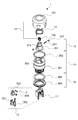
- the emergency stop switch 1 is a switch used for making an emergency stop by putting a device or the like in an energized state in a cut off state, and as shown in FIGS. 1 to 3, the operation unit 11, the torsion coil spring 12, and the latch It comprises a portion 13, a housing portion 14, a contact unit portion 15 and a fixing portion 16.
- the operation unit 11 is configured of a button 101 and a button coil spring 102.
- the button 101 is a cylindrical button disposed at the top of the emergency stop switch 1 as shown in FIGS. 1 to 3.
- the contact C of the contact unit portion 15 described later and the fixed terminal 502 are opened and closed in conjunction with the pressing operation.
- the contact C and the fixed terminal 502 are separated from each other, the device or the like in the energized state is cut off.
- the shape of the button 101 is not particularly limited, but an operator who depresses the emergency stop switch 1 in an emergency can easily recognize that the switch is for stopping the device etc. in an emergency, and is a shape that can be easily pressed with a palm. Is preferred.
- the button coil spring 102 is a coil spring disposed between the button 101 and the plunger body 201.
- the button coil spring 102 slightly absorbs the force applied when the button 101 is pressed. Therefore, the button 101 can have some play. As a result, it is possible to prevent the disconnection of the device or the like due to the erroneous operation on the button 101.
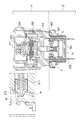
- the torsion coil spring 12 is a coil spring disposed inside the button 101 as shown in FIGS. 2 and 3. One end of the torsion coil spring 12 is joined to a housing 301 of a housing unit 14 described later, and the other end of the torsion coil spring 12 is joined to a button 101 of the operation unit 11.
- the torsion coil spring 12 elastically deforms to restore the pressed button 101 to the state before the pressing operation. .
- the contact point C of the contact unit portion 15 in the released state returns to the state (the state before pressing operation) again in contact with the fixed terminal 502.
- a latch portion 13 is disposed using a space inside the torsion coil spring 12.
- the latch portion 13 is configured to include a plunger body 201, a plunger coil spring 211, and a sliding rod 212, as shown in FIG. As shown in FIGS. 2 and 3, the latch portion 13 is disposed so as to close an opening inside the torsion coil spring 12 and an upper portion of a housing 301 described later.
- a through hole 213 is provided at a central portion of the plunger main body 201, and a plunger coil spring 211 is disposed in the through hole 213. Sliding rods 212 are joined to both ends of the plunger coil spring 211.
- the latch unit 13 When the pressing operation on the button 101 is performed, the latch unit 13 is displaced in the direction of the pressing operation.
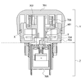
- the plunger body 201 slides the end along the inner wall of the upper opening of the housing 301 described later while expanding and contracting in the direction perpendicular to the direction of pressing operation. .
- the inner wall of the opening at the top of the housing 301 is partially provided with a projection. Therefore, before the end of the sliding rod 212 of the plunger body 201 of the latch unit 13 passes through the top (hereinafter referred to as a "latch point") P of the projection, the contact C of the contact unit 15 described later is fixed. It is biased in the direction of contact with the terminal 502.
- the latch portion 13 biases the contact C in the direction of separating from the fixed terminal 502.
- the latch function will be exhibited.
- the housing portion 14 is configured to include a housing 301 and a waterproof rubber 302.
- the housing 301 is a cylindrical housing having an opening at each of the upper and lower portions.
- a button 101 is disposed on the top of the housing 301 so as to cover the top of the housing 301.
- a groove 303 for disposing the waterproof rubber 302 is provided on the outer periphery of the upper portion of the housing 301, and the waterproof rubber 302 disposed in the groove 303 allows foreign matter such as water and dust to enter the inside of the button 101. To prevent that. As a result, it is possible to prevent a failure, an accident or the like that may occur due to the entry of foreign matter such as water or dust into the button 101.
- a torsion coil spring 12 is disposed between the button 101 and the housing 301. One end of the torsion coil spring 12 is joined to the housing 301, and the other end of the torsion coil spring 12 is joined to the button 101.
- a latch 13 is disposed in the upper opening of the housing 301 so as to close the upper opening of the housing 301.
- the latch point P provided on the inner wall of the housing 301 is located lower than both end portions of the sliding rod 212 of the plunger main body 201. Therefore, the latch unit 13 biases the contact point C of the contact point unit 15 in the direction in which the contact point C contacts the fixed terminal 502.
- a contact unit portion 15 is disposed in the lower opening of the housing 301 so as to close the lower opening of the housing 301.
- the contact unit portion 15 is configured to include a case 501, a fixed terminal 502, a converter 503, a contact coil spring 504, and a contact C.
- the contact unit portion 15 is disposed to close the opening of the lower portion of the housing 301.
- the contact point C is normally in contact with the fixed terminal 502, but is interlocked with the pressing operation on the button 101 to be in the separated state. Further, the contact point C returns to the contact state with the fixed terminal 502 in conjunction with the rotation and the pulling operation on the button 101 after the pressing operation. That is, when the contact point C is separated from the contact state with the fixed terminal 502 in conjunction with the pressing operation on the button 101, the device or the like in the energized state is in the cut-off state. On the other hand, when the contact point C returns to the contact state with the fixed terminal 502 in conjunction with the rotation and the pulling operation on the button 101, the device or the like in the shut-off state returns to the conductive state.
- the emergency stop switch 1 realizes the space saving by arranging the latch portion 13 in the space inside the torsion coil spring 12, a part of the contact unit portion 15 is a space Y outside the control panel. Can be placed. Thus, the portion of the contact unit portion 15 disposed in the space Z inside the control panel can be reduced. As a result, the space inside the control panel can be used effectively.
- the fixing portion 16 is configured of a round nut 401 and a rubber washer 402.
- the round nut 401 is a member for fixing the emergency stop switch 1 to the control panel.
- the rubber washer 402 is disposed between the control board and the round nut 401 to prevent a gap from being formed at the joint between the control board and the emergency stop switch 1.
- the emergency stop switch 1 can be fixed so as not to come off the control panel.
- foreign matter such as water and dust is prevented from invading the inside of the control panel from the junction of the control panel and the emergency stop switch 1.
- latch function When the operator of the emergency stop switch 1 presses the button 101, the latch unit 13 is displaced from the upper portion to the lower portion of the housing portion 14 while being guided by the inner wall of the housing portion 14 in conjunction with the pressing operation.
- the latch portion 13 is provided with a plunger main body 201, and the housing portion 14 is provided with a latch point P on the inner wall. Therefore, the latch function is exhibited before and after the latch portion 13 passes the latch point P of the housing portion 14.
- the latch function is exerted to bias the contact point C and the fixed terminal 502 in the direction of maintaining the contact.
- the latch portion 13 passes the latch point P, the latch function is exerted so that the contact point C is biased in the direction of separating from the fixed terminal 502. That is, when the device or the like is in the energized state (ON state), the latch function is exhibited in the direction of maintaining the energization, and when the device or the like is in the disconnected state (OFF state), the blocking is maintained. The latch function will be exhibited. As a result, it is possible to prevent an erroneous operation by the operator of the device or the like, and to prevent the occurrence of chattering due to the bounce of the contact or the like.
- the graph of FIG. 4 is a graph showing the direction in which the plunger is biased in one pressing operation and the magnitude of the force.
- the horizontal axis of the graph of FIG. 4 is an axis showing the stroke S in one pressing operation on the button 101
- the vertical axis of the graph of FIG. 3 is the direction in which the plunger main body 201 is biased by one pressing operation. It shows the size of the force.
- the initial pressing operation on the button 101 exerts a latch function so as to urge the contact C and the fixed terminal 502 in the direction of maintaining the contact, so the ON state of the device etc.
- Force to try to hold (K1) is strong. Thereafter, as the pressing operation progresses, the force (K1) for maintaining the ON state of the device etc.
- the latch function is also provided to the conventionally existing emergency stop switch. As shown in FIG. 5, a snap ring 704 is fixed to a part of the housing 703 of the conventional emergency stop switch, and a projection 801 is provided on a part of the latch part 702. Therefore, the latch function is exhibited before and after the protrusion 801 passes through the snap ring 704. Specifically, when the latch portion 702 is displaced downward along the inside of the snap ring 704 in conjunction with the pressing operation on the button 701, the snap ring 704 in contact with the protrusion 801 is pushed outward. Then, when the latch portion 702 is further displaced downward, the protrusion 801 does not contact the snap ring 704. For this reason, the snap ring 704 returns to its original shape by elastic deformation from the state where it has been pushed outward.
- the latch function is exhibited before and after the protrusion 801 passes through the snap ring 704.
- the button 701 it is necessary to secure a space for performing a stroke of at least 4.5 mm in the switch.
- a large space X is present in the housing 703, and the entire switch becomes large, and it can not cope with the progress of miniaturization, weight reduction and portability of devices and the like.
- the portion of the contact unit 705 disposed in the space inside the control panel can not be reduced.
- positioned inside a control panel will also be enlarged. As a result, the space inside the control panel can not be used effectively.
- the return function is also provided to the conventionally existing emergency stop switch.
- a torsion coil spring 706 is provided in the conventional emergency stop switch, and when the button 701 is rotated, the button 701 is pressed by elastic deformation of the torsion coil spring 706. Return to the state before the operation.
- the torsion coil spring 706 of the conventional emergency stop switch shown in FIG. 5 is disposed above the space X and the portion that exerts the latch function, the overall size and weight of the switch can be reduced. , Can not contribute to portability.
- the emergency stop switch 1 is an emergency stop because it has been devised to arrange the latch portion 13 inside the torsion coil spring 12.
- the space Z inside the switch 1 can be used effectively. As a result, it is possible to reduce the portion of the contact point unit portion 15 which is disposed in the space Z inside the control panel. As a result, it is possible to provide a compact switch which can effectively utilize the space Z inside the control panel.
- the present invention can be applied to any button type switch, not limited to the emergency stop switch.
- the switch to which the present invention is applied is A cylindrical housing (e.g., housing 301 in FIG. 1); An operation unit (e.g., the operation unit 11 in FIG. 1) having a button (e.g., the button 101 in FIG. 1) which is provided on the top of the housing and receives the pressing operation and the rotation operation; A contact unit section (for example, the contact unit section 15 in FIG. 1) having a contact (for example, the contact C in FIG. 1) that opens in conjunction with the pressing operation on the button; A torsion coil spring (eg, torsion coil spring 12 of FIG.
- the plunger can expand and contract in the direction perpendicular to the direction of the pressing operation.
- the latch portion 13 can be compactly disposed inside the torsion coil spring 12.
- the inner wall of the housing has a shape having a protrusion on a part thereof,
- the projection urges the contact into contact with the contact before the plunger passes the top of the projection (for example, the latch point P in FIGS. 2 and 3), and the plunger After passing the top, the contacts can be biased in an opening direction.
Abstract
機器等の小型化、軽量化、携帯化の進展に対応した、コンパクトかつ安全性の高いスイッチを提供することを課題とする。 操作部11は、筒形のハウジング301の上部に覆設され、押下操作と回転操作とを受付けるボタン101を有する。接点ユニット部15は、ボタンへ101の押下操作に連動して開離する接点Cを有する。ねじりコイルばね12は、ボタン101の内側に配置され、一端がハウジング301に接合され、他端がボタン1に接合されている。ラッチ部13は、押下操作の方向に対して垂直方向に伸縮するプランジャコイルばね211を有し、ねじりコイルばね12の内側に配置され、ボタン101に対して押下操作が行われると、ハウジング301の内壁に沿って滑動棒212を滑動させながら押下操作の方向に変位する。これにより、上記課題を解決することができる。
Description
本発明は、スイッチに関する。
通常、機器等を操作するための制御盤には、誤動作による事故の発生を回避するための非常停止スイッチが設けられている。この非常停止スイッチは、押下操作されると電源を遮断して機器等の稼働を直ちに停止させる。非常停止スイッチには、安全確保の見地から、ボタン部分の形状や、押下操作後の復帰防止等についての様々な規定が存在するため、形状や構造に対して種々の制約が加わる。これにより、非常停止スイッチのボタン部分の形状はキノコ形や円錐形であり、非常停止スイッチの構造はスナップリング等を用いたラッチ機能によって容易に通電状態を復帰させないようにしたものが一般的である。例えば、特許文献1には、開離付勢手段の付勢力の作用により、導電部材の接点が接触状態あるいは接近状態に戻ることを防止できるとする押ボタンスイッチが提案されている。
しかしながら、非常停止スイッチの構成を、種々の制約に対応可能なものにしようとすると、非常停止スイッチ自体が大型化してしまう。これでは、機器等の小型化、軽量化、携帯化の進展に対応することができない。例えば、ロボットへの作業教示用のティーチングペンダントに設けられた非常停止スイッチは、持ち運びに対応させるためにコンパクト化させることが必須となる。また、制御盤に非常停止スイッチを取り付ける際に、非常停止スイッチを構成する部位のうち、制御盤の内側に配置される部位の寸法を短くして、制御盤の内側のスペースを有効利用したいとする要求もある。
本発明は、このような状況に鑑みてなされたものであり、機器等の小型化、軽量化、携帯化の進展に対応した、コンパクトかつ安全性の高いスイッチを提供することを目的とする。
上記目的を達成するため、本発明に係るスイッチは、
筒形のハウジングと、
ハウジングの上部に覆設され、押下操作と回転操作とを受付けるボタンを有する操作部と、
ボタンへの押下操作に連動して開離する接点を有する接点ユニット部と、
ボタンの内側に配置され、一端がハウジングに接合され、他端がボタンに接合されたねじりコイルばねと、
押下操作の方向に対して垂直方向に伸縮するプランジャを有し、ねじりコイルばねの内側に配置され、ボタンに対して押下操作が行われると、ハウジングの内壁に沿ってプランジャの端部を滑動させながら押下操作の方向に変位するラッチ部と、
を備える。
筒形のハウジングと、
ハウジングの上部に覆設され、押下操作と回転操作とを受付けるボタンを有する操作部と、
ボタンへの押下操作に連動して開離する接点を有する接点ユニット部と、
ボタンの内側に配置され、一端がハウジングに接合され、他端がボタンに接合されたねじりコイルばねと、
押下操作の方向に対して垂直方向に伸縮するプランジャを有し、ねじりコイルばねの内側に配置され、ボタンに対して押下操作が行われると、ハウジングの内壁に沿ってプランジャの端部を滑動させながら押下操作の方向に変位するラッチ部と、
を備える。
本発明によれば、ラッチ部がねじりコイルばねの内側に配置されるので、スイッチ内部のスペースを有効利用でき、スイッチ自体をコンパクト化させることができる。その結果、機器等の小型化、軽量化、携帯化の進展に対応した、コンパクトなスイッチを提供することができる。
本発明に係るスイッチにおいて、プランジャは、押下操作の方向に対して垂直方向に伸縮することができる。
本発明によれば、ねじりコイルばねの内側にラッチ部をコンパクトに配置することができる。
本発明によれば、ねじりコイルばねの内側にラッチ部をコンパクトに配置することができる。
本発明に係るスイッチにおいて、ハウジングの内壁は、一部に突起部を有する形状であり、
突起部は、ボタンが押下操作されると、プランジャが突起部の頂部を通過する前は接点が接触する方向に付勢し、プランジャが突起部の頂部を通過した後は接点が開離する方向に付勢することが好ましい。
突起部は、ボタンが押下操作されると、プランジャが突起部の頂部を通過する前は接点が接触する方向に付勢し、プランジャが突起部の頂部を通過した後は接点が開離する方向に付勢することが好ましい。
本発明によれば、ラッチ機能が発揮されるため、プランジャが突起部の頂部を通過する前は接点が接触する方向に付勢し、プランジャが突起部の頂部を通過した後は接点が開離する方向に付勢することとなる。その結果、機器等の操作者による誤操作を防いだり、接点のバウンド等によるチャタリングの発生を防いだりすることができる安全性の高いスイッチを提供することができる。また、本発明によれば、プランジャが突起部の頂部を通過した前後で付勢方向が反転するため、操作者は接点の切換タイミングを明確な操作感の違いで認識できる。
本発明によれば、機器等の小型化、軽量化、携帯化の進展に対応した、コンパクトかつ安全性の高いスイッチを提供することができる。
本発明のスイッチの一実施形態に係る非常停止スイッチ1について、図面を参照しつつ説明する。なお、本発明は下記の実施形態に限定されるものではない。
[基本構成]
非常停止スイッチ1は、通電状態にある機器等を遮断状態にして緊急停止させるために用いられるスイッチであり、図1乃至図3に示すように、操作部11と、ねじりコイルばね12と、ラッチ部13と、ハウジング部14と、接点ユニット部15と、固定部16とで構成される。
非常停止スイッチ1は、通電状態にある機器等を遮断状態にして緊急停止させるために用いられるスイッチであり、図1乃至図3に示すように、操作部11と、ねじりコイルばね12と、ラッチ部13と、ハウジング部14と、接点ユニット部15と、固定部16とで構成される。
以下、非常停止スイッチ1の各構成要素について詳しく説明する。
(操作部)
操作部11は、ボタン101と、ボタンコイルばね102とで構成されている。
操作部11は、ボタン101と、ボタンコイルばね102とで構成されている。
ボタン101は、図1乃至図3に示すように、非常停止スイッチ1の最上部に配置された円筒形のボタンである。ボタン101に対する押下操作が行われると、押下操作に連動して、後述する接点ユニット部15の接点Cと固定端子502とが開離する。接点Cと固定端子502とが開離すると、通電状態にある機器等が遮断状態になる。ボタン101の形状は特に限定されないが、緊急時に非常停止スイッチ1を押下操作する操作者が、機器等を非常停止させるためのスイッチであることを容易に認識でき、かつ掌で押し易い形状であることが好ましい。
ボタンコイルばね102は、ボタン101とプランジャ本体201との間に配置されたコイルばねである。ボタンコイルばね102は、ボタン101が押下される際に加えられる力を若干吸収する。このため、ボタン101に若干の遊びを持たせることができる。その結果、ボタン101に対する誤操作による機器等の遮断を防ぐことができる。
(ねじりコイルばね)
ねじりコイルばね12は、図2及び図3に示すように、ボタン101の内側に配置されたコイルばねである。ねじりコイルばね12の一端は、後述のハウジング部14のハウジング301に接合され、ねじりコイルばね12の他端は、操作部11のボタン101に接合されている。
ねじりコイルばね12は、図2及び図3に示すように、ボタン101の内側に配置されたコイルばねである。ねじりコイルばね12の一端は、後述のハウジング部14のハウジング301に接合され、ねじりコイルばね12の他端は、操作部11のボタン101に接合されている。
ボタン101に対する押下操作が行われた後に、ボタン101に対する回転操作が行われると、ねじりコイルばね12は、弾性変形することにより、押下された状態にあるボタン101を押下操作前の状態に復帰させる。この回転操作により、ボタン101が押下操作前の状態に復帰すると、開離状態にあった接点ユニット部15の接点Cは再び固定端子502と接触した状態(押下操作前の状態)に復帰する。ねじりコイルばね12の内側には、ねじりコイルばね12の内側のスペースを利用して、ラッチ部13が配置されている。
(ラッチ部)
ラッチ部13は、図1に示すように、プランジャ本体201と、プランジャコイルばね211と、滑動棒212とを含むように構成されている。ラッチ部13は、図2及び図3に示すように、ねじりコイルばね12の内側、かつ後述するハウジング301の上部の開口部を塞ぐように配置されている。
ラッチ部13は、図1に示すように、プランジャ本体201と、プランジャコイルばね211と、滑動棒212とを含むように構成されている。ラッチ部13は、図2及び図3に示すように、ねじりコイルばね12の内側、かつ後述するハウジング301の上部の開口部を塞ぐように配置されている。
プランジャ本体201の中心部には貫通孔213が設けられており、この貫通孔213の内部にプランジャコイルばね211が配置されている。プランジャコイルばね211の両端部には滑動棒212が接合されている。
ボタン101に対する押下操作が行われると、ラッチ部13は、押下操作の方向に変位する。ラッチ部13が押下操作の方向に変位すると、プランジャ本体201は、押下操作の方向に対して垂直方向に伸縮しながら、後述するハウジング301の上部の開口部の内壁に沿って端部を滑動させる。
ハウジング301の上部の開口部の内壁は、一部に突起部が設けられている。このため、ラッチ部13は、プランジャ本体201の滑動棒212の端部が突起部の頂部(以下「ラッチ点」と呼ぶ)Pを通過する前は、後述する接点ユニット部15の接点Cが固定端子502と接触する方向に付勢する。これに対して、滑動棒212の端部がラッチ点Pを通過した後は、ラッチ部13は、接点Cが固定端子502と開離する方向に付勢する。
これにより、機器等が通電状態(ON状態)にある場合には、通電を維持させる方向にラッチ機能が発揮され、機器等が遮断状態(OFF状態)にある場合には、遮断を維持させる方向にラッチ機能が発揮されることとなる。その結果、機器等の操作者による誤操作を防いだり、接点のバウンド等によるチャタリングの発生を防いだりすることができる。
(ハウジング部)
ハウジング部14は、ハウジング301と、防水ゴム302とを含むように構成されている。ハウジング301は、上部と下部との夫々に開口部を有する筒形のハウジングである。
ハウジング部14は、ハウジング301と、防水ゴム302とを含むように構成されている。ハウジング301は、上部と下部との夫々に開口部を有する筒形のハウジングである。
ハウジング301の上部には、ハウジング301の上部を覆うようにボタン101が配置されている。ハウジング301の上部の外周には、防水ゴム302を配置させるための溝303が設けられており、溝303に配置された防水ゴム302は、ボタン101の内部に水や埃等の異物が侵入することを防いでいる。その結果、ボタン101の内部に水や埃等の異物の侵入により生じ得る故障や事故等を防ぐことができる。
ボタン101とハウジング301との間には、ねじりコイルばね12が配置されている。ねじりコイルばね12の一端はハウジング301に接合されており、ねじりコイルばね12の他端はボタン101に接合されている。
ボタン101とハウジング301との間には、ねじりコイルばね12が配置されている。ねじりコイルばね12の一端はハウジング301に接合されており、ねじりコイルばね12の他端はボタン101に接合されている。
ハウジング301の上部の開口部には、ハウジング301の上部の開口部を塞ぐようにラッチ部13が配置されている。このとき、ハウジング301の内壁に設けられたラッチ点Pは、プランジャ本体201の滑動棒212の両端部よりも下側に位置している。このため、ラッチ部13は、接点ユニット部15の接点Cが固定端子502と接触する方向に付勢している。
ハウジング301の下部の開口部には、ハウジング301の下部の開口部を塞ぐように接点ユニット部15が配置されている。
ハウジング301の下部の開口部には、ハウジング301の下部の開口部を塞ぐように接点ユニット部15が配置されている。
(接点ユニット部)
接点ユニット部15は、図1に示すように、ケース501と、固定端子502と、転換子503と、接点コイルばね504と、接点Cとを含むように構成されている。接点ユニット部15は、ハウジング301の下部の開口部を塞ぐように配置されている。
接点ユニット部15は、図1に示すように、ケース501と、固定端子502と、転換子503と、接点コイルばね504と、接点Cとを含むように構成されている。接点ユニット部15は、ハウジング301の下部の開口部を塞ぐように配置されている。
接点Cは、通常時は固定端子502と接触状態にあるが、ボタン101に対する押下操作に連動して開離状態となる。また、接点Cは、押下操作された後のボタン101に対する回転及び引張操作に連動して固定端子502との接触状態に復帰する。即ち、ボタン101に対する押下操作に連動して接点Cが固定端子502と接触状態から開離状態になると、通電状態にある機器等が遮断状態となる。これに対して、ボタン101に対する回転及び引張操作に連動して接点Cが固定端子502との接触状態に復帰すると、遮断状態にあった機器等が通電状態に復帰する。
非常停止スイッチ1は、図2及び図3に示すように、接点ユニット部15の一部が制御盤の外側のスペースYに配置される。これに対して、従来型の非常停止スイッチは、図5に示すように、接点ユニット705の全体が制御盤の内側のスペースZに配置される。即ち、非常停止スイッチ1は、ねじりコイルばね12の内側のスペースにラッチ部13を配置することで省スペース化を実現させているため、接点ユニット部15の一部を制御盤の外側のスペースYに配置することができる。これにより、制御盤の内側のスペースZに配置される接点ユニット部15の部位を縮小させることができる。その結果、制御盤の内側のスペースを有効利用することができる。
(固定部)
固定部16は、丸ナット401と、ゴム座金402とで構成されている。
固定部16は、丸ナット401と、ゴム座金402とで構成されている。
丸ナット401は、制御盤に非常停止スイッチ1を固定するための部材である。ゴム座金402は、制御盤と丸ナット401との間に配置され、制御盤と非常停止スイッチ1との接合部に隙間が生じる事を防いでいる。これにより、非常停止スイッチ1が制御盤から外れないように固定することができる。また、制御盤と非常停止スイッチ1との接合部から水や埃等の異物が制御盤の内部に侵入することを防いでいる。その結果、非常停止スイッチ1が制御盤から外れたり、水や埃等が侵入したりすることで生じ得る故障や事故を未然に防ぐことができる。
[ラッチ機能]
非常停止スイッチ1の操作者が、ボタン101に対する押下操作を行うと、ラッチ部13は、押下操作に連動してハウジング部14の内壁にガイドされながらハウジング部14の上部から下部に変位する。
ラッチ部13にはプランジャ本体201が設けられており、ハウジング部14には内壁にラッチ点Pが設けられている。このため、ラッチ部13がハウジング部14のラッチ点Pを通過する前後でラッチ機能が発揮される。
非常停止スイッチ1の操作者が、ボタン101に対する押下操作を行うと、ラッチ部13は、押下操作に連動してハウジング部14の内壁にガイドされながらハウジング部14の上部から下部に変位する。
ラッチ部13にはプランジャ本体201が設けられており、ハウジング部14には内壁にラッチ点Pが設けられている。このため、ラッチ部13がハウジング部14のラッチ点Pを通過する前後でラッチ機能が発揮される。
ボタン101に対する押下操作が行われると、結果的に接点ユニット部15の接点Cが固定端子502と開離することになるが、プランジャ本体201の滑動棒212の端部が、ラッチ点Pを通過するまでは、接点Cと固定端子502との接触を維持させる方向に付勢するようにラッチ機能が発揮される。
これに対して、一度ラッチ部13がラッチ点Pを通過すると、接点Cが固定端子502と開離する方向に付勢するようにラッチ機能が発揮される。
即ち、機器等が通電状態(ON状態)にある場合には、通電を維持させる方向にラッチ機能が発揮され、機器等が遮断状態(OFF状態)にある場合には、遮断を維持させる方向にラッチ機能が発揮されることとなる。その結果、機器等の操作者による誤操作を防いだり、接点のバウンド等によるチャタリングの発生を防いだりすることができる。
これに対して、一度ラッチ部13がラッチ点Pを通過すると、接点Cが固定端子502と開離する方向に付勢するようにラッチ機能が発揮される。
即ち、機器等が通電状態(ON状態)にある場合には、通電を維持させる方向にラッチ機能が発揮され、機器等が遮断状態(OFF状態)にある場合には、遮断を維持させる方向にラッチ機能が発揮されることとなる。その結果、機器等の操作者による誤操作を防いだり、接点のバウンド等によるチャタリングの発生を防いだりすることができる。
図4のグラフは、1回の押下操作でプランジャが付勢する方向と力の大きさとを示すグラフである。図4のグラフの横軸は、ボタン101に対する1回の押下操作におけるストロークSを示す軸であり、図3のグラフの縦軸は、1回の押下操作でプランジャ本体201が付勢する方向と力の大きさを示している。
図4のグラフに示すように、ボタン101に対する押下操作の初期は、接点Cと固定端子502との接触を維持させる方向に付勢するようにラッチ機能が発揮されるため、機器等のON状態を保持しようとする力(K1)が強い。その後、押下操作が進むにつれて、機器等のON状態を保持しようとする力(K1)は次第に弱くなり、プランジャ本体201の滑動棒212の端部がハウジング301のラッチ点Pに至った時点で、機器等のON状態を保持しようとする力(K1)と機器等のOFF状態を保持しようとする力(K2)とが均衡する。そして、プランジャ本体201の滑動棒212の端部がハウジング301のラッチ点Pを通過すると、今度は、機器等のOFF状態を保持しようとする力(K2)が次第に強くなって行く。
図4のグラフに示すように、ボタン101に対する押下操作の初期は、接点Cと固定端子502との接触を維持させる方向に付勢するようにラッチ機能が発揮されるため、機器等のON状態を保持しようとする力(K1)が強い。その後、押下操作が進むにつれて、機器等のON状態を保持しようとする力(K1)は次第に弱くなり、プランジャ本体201の滑動棒212の端部がハウジング301のラッチ点Pに至った時点で、機器等のON状態を保持しようとする力(K1)と機器等のOFF状態を保持しようとする力(K2)とが均衡する。そして、プランジャ本体201の滑動棒212の端部がハウジング301のラッチ点Pを通過すると、今度は、機器等のOFF状態を保持しようとする力(K2)が次第に強くなって行く。
ラッチ機能は、従来から存在する非常停止スイッチにも備わっている。従来から存在する非常停止スイッチのハウジング703の一部には、図5に示すように、スナップリング704が固定されており、ラッチ部702の一部に突起部801が設けられている。このため、突起部801がスナップリング704を通過する前後でラッチ機能が発揮される。
具体的には、ボタン701に対する押下操作に連動してラッチ部702がスナップリング704の内側に沿って下方に変位すると、突起部801に接触したスナップリング704が外側に押し広げられる。そして、ラッチ部702がさらに下方に変位すると、突起部801はスナップリング704に接触しなくなる。このため、スナップリング704は、外側に押し広げられていた状態から弾性変形によって元の形状に戻る。
具体的には、ボタン701に対する押下操作に連動してラッチ部702がスナップリング704の内側に沿って下方に変位すると、突起部801に接触したスナップリング704が外側に押し広げられる。そして、ラッチ部702がさらに下方に変位すると、突起部801はスナップリング704に接触しなくなる。このため、スナップリング704は、外側に押し広げられていた状態から弾性変形によって元の形状に戻る。
このように、従来から存在する非常停止スイッチでは、突起部801がスナップリング704を通過する前後でラッチ機能が発揮される。しかしながら、ボタン701を押下するためには、最低でも4.5mmのストロークを行うためのスペースをスイッチ内に確保する必要がある。このため、図5に示すように、ハウジング703内に大きなスペースXが存在することとなり、スイッチ全体が大型化し、機器等の小型化、軽量化、携帯化の進展に対応することができない。また、制御盤の内側のスペースに配置される接点ユニット705の部位を縮小させることができない。このため、制御盤の内側に配置される部位も大型化してしまう。その結果、制御盤の内側のスペースを有効利用することができない。
[復帰機能]
非常停止スイッチ1の操作者がボタン101に対する押下操作が行われると、結果的に接点ユニット部15の接点Cが固定端子502と開離することになるが、その後、ボタン101に対する回転操作が行われると、ボタン101は、ねじりコイルばね12の弾性変形によって押下操作前の状態に復帰する。
非常停止スイッチ1の操作者がボタン101に対する押下操作が行われると、結果的に接点ユニット部15の接点Cが固定端子502と開離することになるが、その後、ボタン101に対する回転操作が行われると、ボタン101は、ねじりコイルばね12の弾性変形によって押下操作前の状態に復帰する。
復帰機能は、従来から存在する非常停止スイッチにも備わっている。図5に示すように、従来から存在する非常停止スイッチには、ねじりコイルばね706が設けられており、ボタン701に対する回転操作が行われると、ねじりコイルばね706の弾性変形により、ボタン701が押下操作前の状態に復帰する。
しかしながら、図5に示す従来から存在する非常停止スイッチのねじりコイルばね706は、ラッチ機能を発揮する部位や、上述のスペースXよりも上部に配置されるため、スイッチ全体としての小型化、軽量化、携帯化に寄与することができない。
これに対して、非常停止スイッチ1は、図2及び図3に示すように、ねじりコイルばね12の内側にラッチ部13を配置するという、これまでにない工夫が凝らされているため、非常停止スイッチ1の内側のスペースZを有効活用することができる。これにより、接点ユニット部15のうち制御盤の内側のスペースZに配置させる部位を縮小させることができる。その結果、制御盤の内側のスペースZを有効利用することができる、コンパクトなスイッチを提供することができる。
以上、本発明の一実施形態について説明したが、本発明は、上述の実施形態に限定されるものではなく、本発明の目的を達成できる範囲での変形、改良等は本発明に含まれるものである。また、本発明に係る要旨を逸脱しない範囲内であれば種々の変更を施してもよい。
例えば、上述の実施形態では非常停止スイッチとなっているが、非常停止スイッチに限らず、あらゆるボタン型のスイッチに本発明を適用することができる。
以上まとめると、本発明が適用されるスイッチは、次のような構成を取れば足り、各種各様な実施形態を取ることができる。
即ち、本発明が適用されるスイッチ(例えば図1の非常停止スイッチ1)は、
筒形のハウジング(例えば図1のハウジング301)と、
ハウジングの上部に覆設され、押下操作と回転操作とを受付けるボタン(例えば図1のボタン101)を有する操作部(例えば図1の操作部11)と、
ボタンへの押下操作に連動して開離する接点(例えば図1の接点C)を有する接点ユニット部(例えば図1の接点ユニット部15)と、
ボタンの内側に配置され、一端がハウジングに接合され、他端がボタンに接合されたねじりコイルばね(例えば図1のねじりコイルばね12)と、
プランジャ(例えば図1のプランジャ本体201)を有し、ねじりコイルばねの内側に配置され、ボタンに対して押下操作が行われると、ハウジングの内壁に沿ってプランジャの端部(例えば図1の滑動棒212)を滑動させながら押下操作の方向に変位するラッチ部(例えば図1のラッチ部13)と、
を備える。
これにより、機器等の小型化、軽量化、携帯化の進展に対応した、コンパクトなスイッチを提供することができる。
また、本発明に係るスイッチにおいて、プランジャは、押下操作の方向に対して垂直方向に伸縮することができる。
これにより、ねじりコイルばね12の内側にラッチ部13をコンパクトに配置することができる。
これにより、ねじりコイルばね12の内側にラッチ部13をコンパクトに配置することができる。
また、本発明に係るスイッチにおいて、ハウジングの内壁は、一部に突起部を有する形状であり、
突起部は、ボタンが押下操作されると、プランジャが突起部の頂部(例えば図2及び図3のラッチ点P)を通過する前は接点が接触する方向に付勢し、プランジャが突起部の頂部を通過した後は接点が開離する方向に付勢することができる。
これにより、機器等の操作者による誤操作を防いだり、接点のバウンド等によるチャタリングの発生を防いだりすることができる。
突起部は、ボタンが押下操作されると、プランジャが突起部の頂部(例えば図2及び図3のラッチ点P)を通過する前は接点が接触する方向に付勢し、プランジャが突起部の頂部を通過した後は接点が開離する方向に付勢することができる。
これにより、機器等の操作者による誤操作を防いだり、接点のバウンド等によるチャタリングの発生を防いだりすることができる。
1・・・ 非常停止スイッチ
11・・・ 操作部
12・・・ ねじりコイルばね
13・・・ ラッチ部
14・・・ ハウジング部
15・・・ 接点ユニット部
16・・・ 固定部
101・・・ ボタン
102・・・ ボタンコイルばね
201・・・ プランジャ
211・・・ プランジャコイルばね
212・・・ 滑動棒
213・・・ 貫通孔
301・・・ ハウジング
302・・・ 防水ゴム
303・・・ 溝
401・・・ 丸ナット
402・・・ ゴム座金
501・・・ ケース
502・・・ 固定端子
503・・・ 転換子
504・・・ 接点コイルばね
701・・・ ボタン
702・・・ ラッチ部
703・・・ ハウジング
704・・・ スナップリング
705・・・ 接点ユニット
706・・・ ねじりコイルばね
801・・・ 突起部
C・・・ 接点
P・・・ ラッチ点
S・・・ ストローク
X・・・ スペース
Y・・・ スペース
Z・・・ スペース
Claims (3)
- 筒形のハウジングと、
前記ハウジングの上部に覆設され、押下操作と回転操作とを受付けるボタンを有する操作部と、
前記ボタンへの前記押下操作に連動して開離する接点を有する接点ユニット部と、
前記ボタンの内側に配置され、一端が前記ハウジングに接合され、他端が前記ボタンに接合されたねじりコイルばねと、
プランジャを有し、前記ねじりコイルばねの内側に配置され、前記ボタンに対して押下操作が行われると、前記ハウジングの内壁に沿って前記プランジャの一部を滑動させながら前記押下操作の方向に変位するラッチ部と、
を備えるスイッチ。 - 前記プランジャの前記一部が、前記押下操作の方向に対して垂直方向に伸縮する、
請求項1に記載のスイッチ。 - 前記ハウジングの前記内壁は、一部に突起部を有する形状であり、
前記ラッチ部は、前記ボタンが押下操作されると、前記プランジャの前記一部が前記突起部の頂部を通過する前は前記接点が接触する方向に付勢し、前記プランジャの前記一部が前記突起部の頂部を通過した後は前記接点が開離する方向に付勢する、
請求項1又は2に記載のスイッチ。
Priority Applications (3)
| Application Number | Priority Date | Filing Date | Title |
|---|---|---|---|
| EP18863072.7A EP3690908B1 (en) | 2017-09-29 | 2018-09-25 | Switch |
| CN201880062792.1A CN111164720B (zh) | 2017-09-29 | 2018-09-25 | 开关 |
| US16/651,696 US11289289B2 (en) | 2017-09-29 | 2018-09-25 | Emergency stop switch |
Applications Claiming Priority (2)
| Application Number | Priority Date | Filing Date | Title |
|---|---|---|---|
| JP2017-189533 | 2017-09-29 | ||
| JP2017189533A JP6996924B2 (ja) | 2017-09-29 | 2017-09-29 | スイッチ |
Publications (1)
| Publication Number | Publication Date |
|---|---|
| WO2019065627A1 true WO2019065627A1 (ja) | 2019-04-04 |
Family
ID=65903092
Family Applications (1)
| Application Number | Title | Priority Date | Filing Date |
|---|---|---|---|
| PCT/JP2018/035448 WO2019065627A1 (ja) | 2017-09-29 | 2018-09-25 | スイッチ |
Country Status (5)
| Country | Link |
|---|---|
| US (1) | US11289289B2 (ja) |
| EP (1) | EP3690908B1 (ja) |
| JP (1) | JP6996924B2 (ja) |
| CN (1) | CN111164720B (ja) |
| WO (1) | WO2019065627A1 (ja) |
Citations (5)
| Publication number | Priority date | Publication date | Assignee | Title |
|---|---|---|---|---|
| JP2006040606A (ja) * | 2004-07-23 | 2006-02-09 | Yuhshin Co Ltd | 切換スイッチ |
| JP3909082B1 (ja) | 2006-12-04 | 2007-04-25 | Idec株式会社 | 押ボタンスイッチ |
| JP2008311097A (ja) * | 2007-06-15 | 2008-12-25 | Chichibu Fuji Co Ltd | 非常停止用押ボタンスイッチ |
| JP2010232157A (ja) * | 2008-10-27 | 2010-10-14 | Fuji Electric Fa Components & Systems Co Ltd | 押しボタンスイッチ |
| WO2014119140A1 (ja) * | 2013-02-04 | 2014-08-07 | 富士電機機器制御株式会社 | スイッチ装置 |
Family Cites Families (12)
| Publication number | Priority date | Publication date | Assignee | Title |
|---|---|---|---|---|
| DE10011625C1 (de) * | 2000-03-10 | 2001-10-18 | Moeller Gmbh | Notaus-Taste |
| DE10011624C1 (de) * | 2000-03-10 | 2001-07-26 | Moeller Gmbh | Notaus-Taste |
| DE20305387U1 (de) | 2003-04-03 | 2003-07-03 | Eao Esa Zweigniederlassung Der | Not-Aus-Gerät mit integrierten Schaltelementen |
| JP2006019130A (ja) * | 2004-07-01 | 2006-01-19 | Alps Electric Co Ltd | プッシュスイッチ |
| DE102007046999B3 (de) * | 2007-10-01 | 2009-01-02 | Siemens Ag | Betätiger |
| FR2979747B1 (fr) * | 2011-09-07 | 2014-05-23 | Schneider Electric Ind Sas | Dispositif d'arret d'urgence adaptable sur un systeme de dialogue homme-machine |
| CN202905537U (zh) * | 2012-11-29 | 2013-04-24 | 科都电气有限公司 | 一种急停按钮 |
| CN203415438U (zh) * | 2013-09-16 | 2014-01-29 | 乐清市信达利实业有限公司 | 急停按钮开关 |
| CN104851727A (zh) * | 2015-05-25 | 2015-08-19 | 东莞市高特电子有限公司 | 小型机械开关的超薄复位机构及小型机械开关 |
| CN204927132U (zh) * | 2015-07-14 | 2015-12-30 | 中煤科工集团上海研究院 | 一种带定位结构的隔爆型按钮操作机构 |
| CN206236568U (zh) * | 2016-11-03 | 2017-06-09 | 浙江正泰电器股份有限公司 | 急停按钮 |
| TWI603359B (zh) * | 2016-12-22 | 2017-10-21 | Switchgear locking, lifting the structure |
-
2017
- 2017-09-29 JP JP2017189533A patent/JP6996924B2/ja active Active
-
2018
- 2018-09-25 WO PCT/JP2018/035448 patent/WO2019065627A1/ja unknown
- 2018-09-25 CN CN201880062792.1A patent/CN111164720B/zh active Active
- 2018-09-25 US US16/651,696 patent/US11289289B2/en active Active
- 2018-09-25 EP EP18863072.7A patent/EP3690908B1/en active Active
Patent Citations (5)
| Publication number | Priority date | Publication date | Assignee | Title |
|---|---|---|---|---|
| JP2006040606A (ja) * | 2004-07-23 | 2006-02-09 | Yuhshin Co Ltd | 切換スイッチ |
| JP3909082B1 (ja) | 2006-12-04 | 2007-04-25 | Idec株式会社 | 押ボタンスイッチ |
| JP2008311097A (ja) * | 2007-06-15 | 2008-12-25 | Chichibu Fuji Co Ltd | 非常停止用押ボタンスイッチ |
| JP2010232157A (ja) * | 2008-10-27 | 2010-10-14 | Fuji Electric Fa Components & Systems Co Ltd | 押しボタンスイッチ |
| WO2014119140A1 (ja) * | 2013-02-04 | 2014-08-07 | 富士電機機器制御株式会社 | スイッチ装置 |
Non-Patent Citations (1)
| Title |
|---|
| See also references of EP3690908A4 |
Also Published As
| Publication number | Publication date |
|---|---|
| EP3690908B1 (en) | 2022-11-09 |
| JP2019067550A (ja) | 2019-04-25 |
| CN111164720B (zh) | 2022-10-11 |
| US11289289B2 (en) | 2022-03-29 |
| EP3690908A1 (en) | 2020-08-05 |
| EP3690908A4 (en) | 2021-06-16 |
| JP6996924B2 (ja) | 2022-01-17 |
| CN111164720A (zh) | 2020-05-15 |
| US20200234895A1 (en) | 2020-07-23 |
Similar Documents
| Publication | Publication Date | Title |
|---|---|---|
| US10068729B2 (en) | Switch device | |
| EP1801827B1 (en) | A system with a control device and a switching element | |
| JP5340892B2 (ja) | 操作スイッチ | |
| CN112164641A (zh) | 旋转操作器及旋转开关 | |
| EP1876616B1 (en) | Reset device for limit switch and limit switch incorporating such device | |
| JP6280165B2 (ja) | リングメインユニットのインターロック装置 | |
| CN213401064U (zh) | 旋转操作器及旋转开关 | |
| CN107644773B (zh) | 扳钮开关致动机构 | |
| WO2019065627A1 (ja) | スイッチ | |
| KR101927839B1 (ko) | 비상 누름버튼 스위치 | |
| JP7042136B2 (ja) | 押ボタンスイッチの製造方法 | |
| KR100983736B1 (ko) | 모터 보호용 배선 차단기의 외부조작 핸들 조립체 | |
| JP6848707B2 (ja) | 非常停止用押しボタンスイッチ | |
| JP6755582B2 (ja) | 非常停止スイッチ | |
| EP2141715B1 (en) | Safety switch | |
| JP5340893B2 (ja) | スイッチ装置用ばね構造体 | |
| JPH0235144Y2 (ja) | ||
| CN111668062A (zh) | 配电箱 | |
| KR20140009223A (ko) | 압력 스위치 |
Legal Events
| Date | Code | Title | Description |
|---|---|---|---|
| 121 | Ep: the epo has been informed by wipo that ep was designated in this application |
Ref document number: 18863072 Country of ref document: EP Kind code of ref document: A1 |
|
| NENP | Non-entry into the national phase |
Ref country code: DE |
|
| ENP | Entry into the national phase |
Ref document number: 2018863072 Country of ref document: EP Effective date: 20200429 |