WO2019058940A1 - 車両制御装置、車両制御方法および車両制御システム - Google Patents
車両制御装置、車両制御方法および車両制御システム Download PDFInfo
- Publication number
- WO2019058940A1 WO2019058940A1 PCT/JP2018/032536 JP2018032536W WO2019058940A1 WO 2019058940 A1 WO2019058940 A1 WO 2019058940A1 JP 2018032536 W JP2018032536 W JP 2018032536W WO 2019058940 A1 WO2019058940 A1 WO 2019058940A1
- Authority
- WO
- WIPO (PCT)
- Prior art keywords
- lateral force
- tire
- slip ratio
- tire lateral
- force
- Prior art date
- Legal status (The legal status is an assumption and is not a legal conclusion. Google has not performed a legal analysis and makes no representation as to the accuracy of the status listed.)
- Ceased
Links
Images





Classifications
-
- B—PERFORMING OPERATIONS; TRANSPORTING
- B60—VEHICLES IN GENERAL
- B60T—VEHICLE BRAKE CONTROL SYSTEMS OR PARTS THEREOF; BRAKE CONTROL SYSTEMS OR PARTS THEREOF, IN GENERAL; ARRANGEMENT OF BRAKING ELEMENTS ON VEHICLES IN GENERAL; PORTABLE DEVICES FOR PREVENTING UNWANTED MOVEMENT OF VEHICLES; VEHICLE MODIFICATIONS TO FACILITATE COOLING OF BRAKES
- B60T7/00—Brake-action initiating means
- B60T7/12—Brake-action initiating means for automatic initiation; for initiation not subject to will of driver or passenger
- B60T7/22—Brake-action initiating means for automatic initiation; for initiation not subject to will of driver or passenger initiated by contact of vehicle, e.g. bumper, with an external object, e.g. another vehicle, or by means of contactless obstacle detectors mounted on the vehicle
-
- B—PERFORMING OPERATIONS; TRANSPORTING
- B60—VEHICLES IN GENERAL
- B60W—CONJOINT CONTROL OF VEHICLE SUB-UNITS OF DIFFERENT TYPE OR DIFFERENT FUNCTION; CONTROL SYSTEMS SPECIALLY ADAPTED FOR HYBRID VEHICLES; ROAD VEHICLE DRIVE CONTROL SYSTEMS FOR PURPOSES NOT RELATED TO THE CONTROL OF A PARTICULAR SUB-UNIT
- B60W30/00—Purposes of road vehicle drive control systems not related to the control of a particular sub-unit, e.g. of systems using conjoint control of vehicle sub-units
- B60W30/02—Control of vehicle driving stability
-
- B—PERFORMING OPERATIONS; TRANSPORTING
- B60—VEHICLES IN GENERAL
- B60T—VEHICLE BRAKE CONTROL SYSTEMS OR PARTS THEREOF; BRAKE CONTROL SYSTEMS OR PARTS THEREOF, IN GENERAL; ARRANGEMENT OF BRAKING ELEMENTS ON VEHICLES IN GENERAL; PORTABLE DEVICES FOR PREVENTING UNWANTED MOVEMENT OF VEHICLES; VEHICLE MODIFICATIONS TO FACILITATE COOLING OF BRAKES
- B60T8/00—Arrangements for adjusting wheel-braking force to meet varying vehicular or ground-surface conditions, e.g. limiting or varying distribution of braking force
- B60T8/17—Using electrical or electronic regulation means to control braking
- B60T8/176—Brake regulation specially adapted to prevent excessive wheel slip during vehicle deceleration, e.g. ABS
- B60T8/1761—Brake regulation specially adapted to prevent excessive wheel slip during vehicle deceleration, e.g. ABS responsive to wheel or brake dynamics, e.g. wheel slip, wheel acceleration or rate of change of brake fluid pressure
- B60T8/17616—Microprocessor-based systems
-
- B—PERFORMING OPERATIONS; TRANSPORTING
- B60—VEHICLES IN GENERAL
- B60T—VEHICLE BRAKE CONTROL SYSTEMS OR PARTS THEREOF; BRAKE CONTROL SYSTEMS OR PARTS THEREOF, IN GENERAL; ARRANGEMENT OF BRAKING ELEMENTS ON VEHICLES IN GENERAL; PORTABLE DEVICES FOR PREVENTING UNWANTED MOVEMENT OF VEHICLES; VEHICLE MODIFICATIONS TO FACILITATE COOLING OF BRAKES
- B60T8/00—Arrangements for adjusting wheel-braking force to meet varying vehicular or ground-surface conditions, e.g. limiting or varying distribution of braking force
- B60T8/32—Arrangements for adjusting wheel-braking force to meet varying vehicular or ground-surface conditions, e.g. limiting or varying distribution of braking force responsive to a speed condition, e.g. acceleration or deceleration
- B60T8/88—Arrangements for adjusting wheel-braking force to meet varying vehicular or ground-surface conditions, e.g. limiting or varying distribution of braking force responsive to a speed condition, e.g. acceleration or deceleration with failure responsive means, i.e. means for detecting and indicating faulty operation of the speed responsive control means
- B60T8/92—Arrangements for adjusting wheel-braking force to meet varying vehicular or ground-surface conditions, e.g. limiting or varying distribution of braking force responsive to a speed condition, e.g. acceleration or deceleration with failure responsive means, i.e. means for detecting and indicating faulty operation of the speed responsive control means automatically taking corrective action
- B60T8/96—Arrangements for adjusting wheel-braking force to meet varying vehicular or ground-surface conditions, e.g. limiting or varying distribution of braking force responsive to a speed condition, e.g. acceleration or deceleration with failure responsive means, i.e. means for detecting and indicating faulty operation of the speed responsive control means automatically taking corrective action on speed responsive control means
-
- B—PERFORMING OPERATIONS; TRANSPORTING
- B60—VEHICLES IN GENERAL
- B60W—CONJOINT CONTROL OF VEHICLE SUB-UNITS OF DIFFERENT TYPE OR DIFFERENT FUNCTION; CONTROL SYSTEMS SPECIALLY ADAPTED FOR HYBRID VEHICLES; ROAD VEHICLE DRIVE CONTROL SYSTEMS FOR PURPOSES NOT RELATED TO THE CONTROL OF A PARTICULAR SUB-UNIT
- B60W10/00—Conjoint control of vehicle sub-units of different type or different function
- B60W10/04—Conjoint control of vehicle sub-units of different type or different function including control of propulsion units
-
- B—PERFORMING OPERATIONS; TRANSPORTING
- B60—VEHICLES IN GENERAL
- B60W—CONJOINT CONTROL OF VEHICLE SUB-UNITS OF DIFFERENT TYPE OR DIFFERENT FUNCTION; CONTROL SYSTEMS SPECIALLY ADAPTED FOR HYBRID VEHICLES; ROAD VEHICLE DRIVE CONTROL SYSTEMS FOR PURPOSES NOT RELATED TO THE CONTROL OF A PARTICULAR SUB-UNIT
- B60W10/00—Conjoint control of vehicle sub-units of different type or different function
- B60W10/18—Conjoint control of vehicle sub-units of different type or different function including control of braking systems
- B60W10/184—Conjoint control of vehicle sub-units of different type or different function including control of braking systems with wheel brakes
-
- B—PERFORMING OPERATIONS; TRANSPORTING
- B60—VEHICLES IN GENERAL
- B60W—CONJOINT CONTROL OF VEHICLE SUB-UNITS OF DIFFERENT TYPE OR DIFFERENT FUNCTION; CONTROL SYSTEMS SPECIALLY ADAPTED FOR HYBRID VEHICLES; ROAD VEHICLE DRIVE CONTROL SYSTEMS FOR PURPOSES NOT RELATED TO THE CONTROL OF A PARTICULAR SUB-UNIT
- B60W10/00—Conjoint control of vehicle sub-units of different type or different function
- B60W10/20—Conjoint control of vehicle sub-units of different type or different function including control of steering systems
-
- B—PERFORMING OPERATIONS; TRANSPORTING
- B60—VEHICLES IN GENERAL
- B60W—CONJOINT CONTROL OF VEHICLE SUB-UNITS OF DIFFERENT TYPE OR DIFFERENT FUNCTION; CONTROL SYSTEMS SPECIALLY ADAPTED FOR HYBRID VEHICLES; ROAD VEHICLE DRIVE CONTROL SYSTEMS FOR PURPOSES NOT RELATED TO THE CONTROL OF A PARTICULAR SUB-UNIT
- B60W30/00—Purposes of road vehicle drive control systems not related to the control of a particular sub-unit, e.g. of systems using conjoint control of vehicle sub-units
- B60W30/18—Propelling the vehicle
- B60W30/18009—Propelling the vehicle related to particular drive situations
- B60W30/18145—Cornering
-
- B—PERFORMING OPERATIONS; TRANSPORTING
- B60—VEHICLES IN GENERAL
- B60W—CONJOINT CONTROL OF VEHICLE SUB-UNITS OF DIFFERENT TYPE OR DIFFERENT FUNCTION; CONTROL SYSTEMS SPECIALLY ADAPTED FOR HYBRID VEHICLES; ROAD VEHICLE DRIVE CONTROL SYSTEMS FOR PURPOSES NOT RELATED TO THE CONTROL OF A PARTICULAR SUB-UNIT
- B60W30/00—Purposes of road vehicle drive control systems not related to the control of a particular sub-unit, e.g. of systems using conjoint control of vehicle sub-units
- B60W30/18—Propelling the vehicle
- B60W30/18172—Preventing, or responsive to skidding of wheels
-
- B—PERFORMING OPERATIONS; TRANSPORTING
- B60—VEHICLES IN GENERAL
- B60T—VEHICLE BRAKE CONTROL SYSTEMS OR PARTS THEREOF; BRAKE CONTROL SYSTEMS OR PARTS THEREOF, IN GENERAL; ARRANGEMENT OF BRAKING ELEMENTS ON VEHICLES IN GENERAL; PORTABLE DEVICES FOR PREVENTING UNWANTED MOVEMENT OF VEHICLES; VEHICLE MODIFICATIONS TO FACILITATE COOLING OF BRAKES
- B60T2240/00—Monitoring, detecting wheel/tyre behaviour; counteracting thereof
- B60T2240/04—Tyre deformation
-
- B—PERFORMING OPERATIONS; TRANSPORTING
- B60—VEHICLES IN GENERAL
- B60W—CONJOINT CONTROL OF VEHICLE SUB-UNITS OF DIFFERENT TYPE OR DIFFERENT FUNCTION; CONTROL SYSTEMS SPECIALLY ADAPTED FOR HYBRID VEHICLES; ROAD VEHICLE DRIVE CONTROL SYSTEMS FOR PURPOSES NOT RELATED TO THE CONTROL OF A PARTICULAR SUB-UNIT
- B60W2520/00—Input parameters relating to overall vehicle dynamics
- B60W2520/26—Wheel slip
-
- B—PERFORMING OPERATIONS; TRANSPORTING
- B60—VEHICLES IN GENERAL
- B60W—CONJOINT CONTROL OF VEHICLE SUB-UNITS OF DIFFERENT TYPE OR DIFFERENT FUNCTION; CONTROL SYSTEMS SPECIALLY ADAPTED FOR HYBRID VEHICLES; ROAD VEHICLE DRIVE CONTROL SYSTEMS FOR PURPOSES NOT RELATED TO THE CONTROL OF A PARTICULAR SUB-UNIT
- B60W2552/00—Input parameters relating to infrastructure
- B60W2552/40—Coefficient of friction
-
- B—PERFORMING OPERATIONS; TRANSPORTING
- B60—VEHICLES IN GENERAL
- B60W—CONJOINT CONTROL OF VEHICLE SUB-UNITS OF DIFFERENT TYPE OR DIFFERENT FUNCTION; CONTROL SYSTEMS SPECIALLY ADAPTED FOR HYBRID VEHICLES; ROAD VEHICLE DRIVE CONTROL SYSTEMS FOR PURPOSES NOT RELATED TO THE CONTROL OF A PARTICULAR SUB-UNIT
- B60W2720/00—Output or target parameters relating to overall vehicle dynamics
- B60W2720/26—Wheel slip
Definitions
- the present invention relates to a vehicle control device, a vehicle control method, and a vehicle control system.
- Patent Document 1 discloses a technique of determining a target slip ratio of each wheel from a target tire lateral force of each wheel and a target tire longitudinal force, and controlling an actuator to achieve the determined target slip ratio.
- One object of the present invention is to provide a vehicle control device, a vehicle control method and a vehicle control system capable of optimizing the balance between the target tire lateral force and the target tire longitudinal force.
- a vehicle control apparatus is configured to calculate a first difference which is a difference between a tire lateral force and a target tire lateral force with respect to any slip ratio in a correlation between a tire slip ratio of a wheel portion and a tire lateral force.
- a first difference which is a difference between a tire lateral force and a target tire lateral force with respect to any slip ratio in a correlation between a tire slip ratio of a wheel portion and a tire lateral force.
- Command is output to an actuator related to control and drive of the vehicle.
- the balance between the target tire lateral force and the target tire longitudinal force can be optimized.
- FIG. 1 is a configuration diagram of a vehicle control system 1 according to an automatic driving of Embodiment 1. It is a control block diagram of vehicle slip control part 8d. It is a flowchart which shows the flow of the optimal slip ratio arithmetic processing which VMCU8 performs. It is a flowchart which shows the flow of tire lateral force maximum value calculation processing. It is an example of a slip ratio-tire lateral force characteristic normalization map. It is a flowchart which shows the flow of the optimal slip ratio arithmetic processing. It is an example of a slip ratio-tire longitudinal force characteristic normalization map. It is an example of a slip ratio-tire lateral force characteristic normalization map. It is an example of the 2nd difference to each slip ratio.
- slip ratio one example of tire lateral force characteristics and tire longitudinal force characteristics. It is an example of a tire longitudinal force and a tire lateral force realized with an optimal slip ratio.
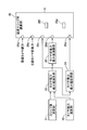
- FIG. 1 is a block diagram of a vehicle control system 1 according to the automatic driving of the first embodiment.
- the vehicle control system 1 is mounted on a vehicle having an engine 2 as a power source.
- the vehicle control system 1 includes a locator 3, a camera unit 4, a radar 5, a vehicle behavior sensor unit (vehicle behavior detection unit) 6, an automatic driving control unit (hereinafter ADCU) 7 and a vehicle motion control unit (vehicle motion control device: hereafter VMCU) ) 8).
- the locator 3 has an inertial sensor such as a Global Navigation Satellite System (GNSS) receiver and a gyro sensor.
- GNSS Global Navigation Satellite System
- the locator 3 measures the position of the host vehicle based on the signals from the plurality of artificial satellites received by the GNSS receiver and the measurement results of the inertial sensor.
- the position of the host vehicle is the center of gravity of the vehicle, the geometric center, or the center of the rear wheel axle.
- the camera unit 4 has a stereo camera which images a predetermined range in front of the host vehicle by two CCDs.
- the camera unit 4 calculates the deviation of the image captured by the stereo camera, recognizes the object (obstacle) by the baseline length, and calculates the distance to the object.
- the radar 5 emits, for example, millimeter waves from the transmitting antenna toward the front of the host vehicle.
- the radar 5 receives the millimeter wave reflected by the object by the receiving antenna, and calculates the distance to the object.
- the vehicle behavior sensor unit 6 is an integrated unit of sensors for detecting vehicle behavior such as lateral acceleration, longitudinal acceleration, yaw rate, and wheel speed.
- the ADC U 7 matches the position of the vehicle located by the locator 3 with the dynamic map to estimate the current position of the vehicle.
- the ADCU 7 recognizes the situation around the host vehicle based on the distance to the object calculated by the camera unit 4 and the radar 5, and attempts to improve the estimation accuracy with reference to the situation around the host vehicle.
- Situations around the host vehicle include, for example, curvature (curvature radius) of a curve, road information such as rotation angle, start position, moving objects (pedestrians, bicycles, motorcycles, leading vehicles, vehicles in adjacent lanes, etc.) Falling objects on the road, traffic signals, guardrails, curbs, road signs, road markings, parcel lines, trees, etc.
- the ADCU 7 outputs, to the VMCU 8, the destination input by the driver's switch operation or the like, the current position of the host vehicle estimated and the situation around it.
- the VMCU 8 generates a target track of the host vehicle, and provides a command for realizing the target track with the control unit (engine of each of the actuators (engine 2, brake unit 9, electric power steering apparatus 10) mounted on the host vehicle. It outputs to the control unit 13, the brake control unit 14, and the electric power steering control unit 15).
- the engine control unit 13, the brake control unit 14, and the electric power steering control unit 15 control the corresponding actuators in accordance with the command output from the VMCU 8.
- the brake unit 9 controls the wheel cylinder hydraulic pressure of each wheel (wheel unit) represented by the anti-slip device, and can individually adjust the braking torque applied to each wheel.
- the electric power steering apparatus 10 can steer a front wheel, which is a steering wheel, to an arbitrary angle using an output torque of an electric motor.
- the VMCU 8 has a traveling position control unit 8a, a vehicle attitude control unit 8b, a tire force control unit 8c, a wheel slip control unit 8d, and an actuator output unit 8e.
- the traveling position control unit 8a generates a target track of the host vehicle related to the automatic driving based on the destination and the current position.
- the target trajectory is a target trajectory point (target position) of the vehicle after the forward gaze time (forward gaze distance / vehicle speed). Further, the traveling position control unit 8a generates a target vehicle speed at the generated target trajectory point.
- the traveling position control unit 8a calculates a target lateral force and a target longitudinal force of the vehicle for achieving the target trajectory point and the target vehicle speed.
- the vehicle attitude control unit 8b corrects the calculated target lateral force and target longitudinal force of the vehicle based on the situation (such as an obstacle) around the own vehicle. Further, the vehicle attitude control unit 8b generates a target yaw angle at the target trajectory point, and calculates a target yaw moment to be applied to the vehicle to realize the target yaw angle.
- the yaw angle is an angle between the longitudinal axis direction of the host vehicle and a reference axial direction (such as the x-axis direction of the road surface fixed coordinate system) fixed to the road surface.
- the tire force control unit (target tire lateral force calculation unit, target tire longitudinal force calculation unit) 8c is a target tire lateral force of each wheel for achieving the corrected target lateral force, target longitudinal force and target yaw moment of the vehicle. And calculate the target tire longitudinal force.
- the target tire lateral force and the target tire longitudinal force are values obtained by giving priority to the target lateral force of the vehicle and the target yaw moment of the vehicle over the target longitudinal force of the vehicle. That is, the target tire lateral force and the target tire front and rear of each wheel are set such that the deviation between the target lateral force and the target yaw moment and the actual lateral force and the yaw moment becomes smaller than the deviation between the target longitudinal force and the actual longitudinal force. Set the force.
- the tire force control unit 8c determines the share of each actuator (engine 2, brake unit 9, electric power steering device 10) for achieving the target tire lateral force and the target tire longitudinal force of each wheel, and the electric power steering A steering command according to the share of the apparatus 10 is generated.
- the wheel slip control unit 8d calculates the optimum slip ratio of each wheel for realizing the determined share of the engine 2 and the brake unit 9, and gives a braking / driving force command for achieving the optimum slip ratio at each wheel. Generate The method of calculating the optimal slip ratio will be described later.
- the actuator output unit 8 e outputs the generated steering command to the electric power steering control unit 15, and outputs the generated braking / driving force command to the engine control unit 13 and the brake control unit 14.
- FIG. 2 is a control block diagram of the wheel slip control unit 8d.
- the slip ratio calculating unit 21 calculates the slip ratio of each wheel.
- the slip ratio is a value obtained by dividing the absolute value of the difference between the wheel speed and the vehicle speed detected by the vehicle behavior sensor unit 6 by the vehicle speed.
- the vehicle speed is estimated from the wheel speed of each wheel. At the time of braking, the highest value of each wheel speed is taken as the vehicle speed, and at the time of acceleration, the lowest value of each wheel speed is taken as the vehicle speed.
- the tire lateral force calculation unit 22 calculates the tire lateral force of each wheel using the two-wheel model of the vehicle from the yaw rate, lateral acceleration and longitudinal acceleration detected by the vehicle behavior sensor unit 6.
- the tire lateral force maximum value calculation unit (maximum tire lateral force calculation unit) 23 calculates a tire lateral force maximum value, which is the maximum tire lateral force that can be generated by each wheel, from the slip ratio of each wheel and the tire lateral force. Details of the calculation method will be described later.
- the tire lateral force maximum value storage unit 24 stores the calculated tire lateral force maximum value of each wheel as a tire lateral force maximum value storage value.
- the tire lateral force maximum value storage value is updated each time the tire lateral force maximum value of each wheel is calculated.
- a tire longitudinal force maximum value computing unit (maximum tire longitudinal force computing unit) 25 computes a tire longitudinal force maximum value that is the maximum tire longitudinal force that each wheel can generate from the tire lateral force maximum value of each wheel. Details of the calculation method will be described later.
- the optimum slip ratio calculation unit 26 includes a target tire lateral force input unit 26a, a target tire longitudinal force input unit 26b, a tire lateral force maximum value input unit (maximum tire lateral force input unit) 26c, and a tire longitudinal force maximum value input unit (maximum A tire longitudinal force input unit 26d, a tire lateral force maximum value stored value input unit (stored maximum tire lateral force input unit) 26e, a tire lateral force difference computing unit 26f, and a tire longitudinal force difference computing unit 26g.
- the target tire lateral force input unit 26a inputs the target tire lateral force of each wheel.
- the target tire longitudinal force input unit 26b inputs the target tire longitudinal force of each wheel.
- the tire lateral force maximum value input unit 26c inputs the tire lateral force maximum value of each wheel.
- the tire longitudinal force maximum value input unit 26d inputs the tire longitudinal force maximum value of each wheel.
- the tire lateral force maximum value storage value input unit 26e inputs the tire lateral force maximum value storage value of each wheel.
- the tire lateral force difference calculation unit 26 f calculates, for each wheel, a first difference that is an absolute value of a difference between the tire lateral force and the target tire lateral force at each slip ratio of the current tire lateral force characteristic.
- the tire longitudinal force difference computation unit 26g computes, for each wheel, a second difference that is an absolute value of a difference between the tire longitudinal force and the target tire longitudinal force at each slip ratio of the current tire longitudinal force characteristic.
- the optimum slip ratio calculation unit 26 calculates, for each wheel, a slip ratio that minimizes the sum of the first difference and the second difference as the optimum slip ratio. The flow of the optimal slip ratio calculation process will be described below with reference to FIG.
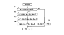
- FIG. 3 is a flow chart showing the flow of the optimal slip ratio calculation process performed by the VMCU 8. The processing of each step is performed for all the wheels.
- step S1 it is determined whether the slip ratio calculated by the slip ratio calculation unit 21 is within an expected normal range. In the case of YES, the process proceeds to step S2, and in the case of NO, the process proceeds to step S5.
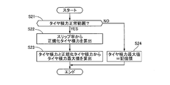
- step S2 the tire lateral force maximum value is determined. It is a flowchart which shows the flow of tire lateral force maximum value calculation processing.
- step S21 it is determined whether the tire lateral force calculated by the tire lateral force calculation unit 22 is within an assumed normal range. In the case of YES, the process proceeds to step S22, and in the case of NO, the process proceeds to step S24.
- step S22 the normalized tire lateral force is calculated from the current slip ratio with reference to the slip ratio-tire lateral force normalized characteristic map at the current tire slip angle.
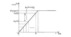
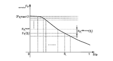
- FIG. 5 shows an example of a slip ratio-tire lateral force characteristic normalization map. This map is obtained by normalizing the relationship between the slip ratio S and the tire lateral force Fy such that the tire lateral force maximum value Fyimax becomes 1 as the slip ratio-tire lateral force characteristic map. By referring to this map, normalized tire lateral force normalizeFyi can be obtained from the current slip ratio Sicurrent.
- step S23 a tire lateral force maximum value Fyimax is calculated from the current tire lateral force Fyicurrent and the normalized tire lateral force normalize Fyi using the following equation.
- Fyimax Fyicurrent / normalizeFyi
- step S24 the tire lateral force maximum value stored value is set as the tire lateral force maximum value Fyimax.
- step S4 an optimal slip ratio is determined.
- FIG. 6 is a flowchart showing the flow of the optimal slip ratio calculation process.
- step S41 as shown in FIG. 7, the tire longitudinal force Fxi (Si) for each slip ratio Si is calculated from the tire longitudinal force maximum value Fximax with reference to the slip ratio-tire longitudinal force characteristic normalization map.
- step S42 as shown in FIG.
- the tire lateral force Fyi (Si) for each slip ratio Si is calculated from the tire lateral force maximum value Fyimax using a slip ratio-tire lateral force characteristic normalization map.
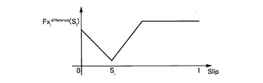
- a second difference Fxidifference (Si) which is an absolute value
- FIG. 9 shows an example of the second difference with respect to each slip ratio.
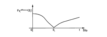
- a first difference Fyidifference (Si) which is an absolute value
- FIG. 10 shows an example of the first difference with respect to each slip ratio.
- step S44 weighting is performed on the first difference Fyidifference (Si) and the second difference Fxidifference (Si), and the total value Fidifference (Si) is calculated.
- Fidifference (Si) ⁇ x ⁇ Fxidifference (Si) + ⁇ y ⁇ Fyidifference (Si)
- ⁇ x and ⁇ y determine the characteristics of the vehicle behavior, and can be determined in advance depending on what kind of vehicle is to be made. Also, it may be changed in real time according to the traveling state or the like.
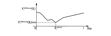
- step S45 as shown in FIG. 11, the slip ratio Si at which the total value Fidifference (Si) is the minimum value Fidifference (Si) min is determined, and this value is taken as the optimum slip ratio Si optimal.
- a predetermined slip ratio set in advance is set as the optimum slip ratio Sioptimal.
- FIG. 12 shows an example of slip ratio-tire lateral force characteristics and tire longitudinal force characteristics at a certain slip angle. As shown in FIG. 12, since the tire lateral force characteristics and the tire longitudinal force characteristics with respect to the slip rate are different, it is rare that the slip rates that satisfy both the target tire lateral force and the target tire longitudinal force coincide with each other.
- a first difference Fyidifference (Si), which is an absolute value of a difference between the target tire lateral force Fyitarget and the tire lateral force Fyi (Si), and the target tire longitudinal force Fxitarget A slip ratio at which a total value Fidifference (Si) with a second difference Fxidifference (Si), which is an absolute value of a difference with the tire longitudinal force Fxi (Si), becomes a minimum value Fidifference (Si) min is taken as an optimum slip ratio Sioptimal. That is, as shown in FIG.
- control of lateral force and longitudinal force of the vehicle especially on a low ⁇ road surface is very important from the viewpoint of ensuring robustness.
- the tire lateral force and the tire longitudinal force of each wheel can be accurately controlled regardless of the road surface ⁇ (the road surface friction coefficient between the tire and the road surface).
- ⁇ the road surface friction coefficient between the tire and the road surface.
- the control accuracy of the lateral force and the longitudinal force of the vehicle can be improved, it is possible to realize both spin avoidance and line traceability.
- the disturbance of the vehicle behavior is fed back, and the slip control is performed in the direction in which the slip ratio of the wheel becomes smaller.
- the slip is performed so that the balance between the target tire lateral force and the target tire longitudinal force is optimized in a state in which the vehicle behavior is not disturbed, that is, in a state in which the anti-slip device is not operating. It controls. Therefore, even in a scene in which the slip ratio is not increased by the conventional skid prevention device, the slip ratio of the wheel may be increased depending on the optimum slip ratio.
- the slip ratio to be minimized is taken as the optimum slip ratio Sioptimal.
- the tire lateral force maximum value calculation unit 23 calculates a normalized tire lateral force normalizeFyi from the current slip ratio Sicurrent using the slip ratio-tire lateral force normalization characteristic map, and calculates the normalized tire lateral force normalizeFyi and the current tire laterality.
- the tire lateral force maximum value Fyimax is calculated from the force Fyicurrent. If the tire lateral force maximum value Fyimax is known, the current slip ratio-tire lateral force characteristic can be obtained from the slip ratio-tire lateral force normalized characteristic map.
- the tire longitudinal force maximum value calculation unit 25 assumes a tire friction circle as a true circle, and obtains a tire longitudinal force maximum value Fximax from the tire lateral force maximum value Fyimax.
- the current slip ratio-tire longitudinal force characteristic can be obtained from the slip ratio-tire longitudinal force normalized characteristic map. Therefore, in the first embodiment, the correlation between the current slip ratio and the tire force (tire lateral force, tire longitudinal force) can be obtained without estimating the wheel load of each wheel or the road surface ⁇ .
- the tire lateral force maximum value calculation unit 23 stores the tire lateral force maximum value storage value stored in the tire lateral force maximum value storage unit 24 when the tire lateral force calculated by the tire lateral force calculation unit 22 is out of the normal range. Let tire lateral force maximum value Fyimax. As a result, even if an abnormality occurs in the vehicle behavior sensor unit 6, the optimal slip ratio Sioptimal can be calculated, so that automatic driving can be continued.
- the optimum slip ratio calculation unit 26 sets a predetermined slip ratio set in advance as the optimum slip ratio Sioptimal. As a result, it is possible to prevent the target tire lateral force and the target tire longitudinal force from becoming unbalanced due to the improper optimum slip ratio Sioptimal.
- the actuator output unit 8e generates a braking / driving force command for achieving the optimum slip ratio Sioptimal at each wheel.
- the optimum slip ratio Sioptimal can be achieved for all wheels, and it is possible to achieve both spin avoidance and line traceability.
- the concrete composition of the present invention is not limited to the composition of the embodiment, and there are design changes within the scope of the present invention. Also included in the present invention. In addition, any combination or omission of each component described in the claims and the specification is possible within a range in which at least a part of the above-mentioned problems can be solved, or in a range that exerts at least a part of the effect. It is.
- the wheel to which the optimal slip ratio control is applied may be at least one wheel. For example, a wheel having the largest friction circle among four wheels may be selected, and the optimum slip ratio control may be applied to the wheel.
- optimal slip ratio control may be applied to only the front wheels or only the rear wheels.
- At least one or all of the traveling position control unit 8a, the vehicle posture control unit 8b, and the tire force control unit 8c may be configured to be provided outside the VMCU 8 (ADCU 7 or another external control unit).
- At least one or all of the slip ratio calculation unit 21, the tire lateral force calculation unit 22, the tire lateral force maximum value calculation unit 23, the tire lateral force maximum value storage unit 24 or the tire longitudinal force maximum value calculation unit 25 outside the VMCU 8 It may be configured to be provided in the ADCU 7 or another control unit.
- the method of calculating the tire lateral force and the slip ratio is arbitrary.
- a target tire lateral force input unit to which a target tire lateral force to be generated on a wheel unit of the vehicle, which is obtained based on a set route on which the vehicle is to travel is input;
- a target tire longitudinal force input unit to which a target tire longitudinal force to be generated in the wheel unit is input, which is obtained based on the set route, and a correlation between a tire slip ratio of the wheel unit and a tire lateral force
- the first difference which is the difference between the tire lateral force and the target tire lateral force for any slip rate, and the tire longitudinal force and the target tire for any slip rate in the correlation between the slip rate and the tire longitudinal force
- a command for achieving the optimum slip ratio corresponding to the minimum value of the sum of the second difference which is the difference with the longitudinal force is output to the actuator related to the control and drive of the vehicle Comprising an actuator output unit that, the.
- the vehicle control device is configured to generate a tire lateral generated on the wheel portion based on vehicle behavior information detected by a vehicle behavior detection unit that detects behavior of the vehicle.
- the maximum tire lateral force input portion to which the maximum tire lateral force that can be generated at the wheel portion is input which is determined based on the force and the slip ratio, and is determined based on the maximum tire lateral force.
- a maximum tire longitudinal force input unit for receiving the maximum tire longitudinal force that can be generated in the wheel unit; and the actuator output unit is configured to calculate the correlation between the slip ratio and the tire lateral force based on the maximum tire lateral force The relationship is determined, and the correlation between the slip ratio and the tire longitudinal force is determined from the maximum tire longitudinal force.
- the optimal slip ratio may be a first weighted difference obtained by performing a first weighting on the first difference, and a second weighted for the second difference. It can be obtained by summing the two weighted differences.
- the first weighting is ⁇ x and the second weighting ⁇ y
- the following formula ⁇ x + ⁇ y 1 Satisfy.
- the first weighting and the second weighting are preset based on vehicle specifications.
- the first weighting and the second weighting are changed according to a traveling state of the vehicle.
- the vehicle control device stores the stored maximum tire lateral force stored in the maximum tire lateral force storage unit that stores the maximum tire lateral force.
- the stored maximum tire lateral force is input to the stored maximum tire lateral force input unit, and the maximum tire longitudinal force input unit receives the maximum tire.
- a stored maximum tire longitudinal force obtained based on the stored maximum tire lateral force is input instead of the lateral force.
- the actuator output unit replaces the command for achieving the optimum slip ratio when an abnormality occurs in the vehicle behavior detection unit, the target tire longitudinal force A command for achieving a predetermined slip ratio obtained based on the target tire longitudinal force input to the input unit is output to the actuator.
- the actuator output unit outputs a command for achieving the optimal slip ratio to all the wheels of the wheel unit to the actuator.
- the actuator output unit outputs, to the actuator, a command for achieving the optimum slip ratio in at least one of the wheel portions.
- the vehicle control method includes a target tire lateral force and a target tire longitudinal force to be generated on a wheel portion of the vehicle, which is obtained based on a set route on which the vehicle is to travel.
- a first difference which is a difference between the tire lateral force and the target tire lateral force with respect to an arbitrary slip ratio in the correlation between the tire slip ratio of the wheel portion and the tire lateral force, and the slip ratio
- the wheel part is obtained based on the tire lateral force generated on the wheel part and the slip ratio, which is obtained based on the detected vehicle behavior information.
- Accepting the input of the maximum tire lateral force that can be generated, and the input of the maximum tire longitudinal force that can be generated in the wheel portion, which is obtained based on the maximum tire lateral force, and the slip ratio from the maximum tire lateral force The correlation between the tire lateral force and the tire lateral force is determined, and the correlation between the slip ratio and the tire longitudinal force is determined from the maximum tire longitudinal force.
- the optimal slip ratio may be a first weighted difference obtained by performing a first weighting on the first difference, and a second weighted for the second difference. It can be obtained by summing the two weighted differences.
- the first weighting is ⁇ x and the second weighting ⁇ y
- the following formula ⁇ x + ⁇ y 1 Satisfy.
- the vehicle control system generates the vehicle behavior detection unit that detects the behavior of the vehicle, and the wheel control unit of the vehicle based on the vehicle behavior information detected by the vehicle behavior detection unit.
- a tire lateral force calculating unit for determining a tire lateral force, a slip ratio calculating unit for determining a slip ratio of the wheel unit based on the vehicle behavior information, and the wheel based on a set route on which the vehicle is to travel
- a target tire lateral force calculating unit for determining a target tire lateral force to be generated in the unit;
- a target tire longitudinal force calculating unit for determining a target tire longitudinal force to be generated in the wheel unit based on the set route;
- a first difference which is the difference between the tire lateral force and the target tire lateral force, is calculated for any slip ratio in the correlation between the tire slip ratio of the wheel and the tire lateral force.
- Tire longitudinal force difference computation for determining a second difference which is a difference between the tire longitudinal force and the target tire longitudinal force with respect to an arbitrary slip ratio in the correlation between the tire lateral force difference computing unit and the slip ratio and the tire longitudinal force
- an optimum slip ratio calculating unit for obtaining an optimum slip ratio corresponding to a minimum value of the sum of the first difference and the second difference, and a command for achieving the optimum slip ratio regarding braking and driving of the vehicle
- an actuator output unit for outputting to the actuator.
- the vehicle control system is configured to calculate the tire lateral force calculated by the tire lateral force calculation unit and the slip ratio calculated by the slip ratio calculation unit.
- a maximum tire lateral force calculation unit for determining a maximum tire lateral force that can be generated in the wheel unit, and a maximum tire longitudinal force calculation unit for determining a maximum tire longitudinal force that can be generated in the wheel unit based on the maximum tire lateral force;
- the tire lateral force difference calculating unit determines the correlation between the slip ratio and the tire lateral force from the maximum tire lateral force, and the tire longitudinal force difference calculating unit determines the slip ratio and the tire longitudinal direction. The correlation with force is determined from the maximum tire longitudinal force.
- the optimal slip ratio may be a first weighted difference obtained by performing a first weighting on the first difference, and a second weighted for the second difference. It can be obtained by summing the two weighted differences.
- the first weighting is ⁇ x and the second weighting ⁇ y
- the following formula ⁇ x + ⁇ y 1 Satisfy.
Landscapes
- Engineering & Computer Science (AREA)
- Transportation (AREA)
- Mechanical Engineering (AREA)
- Automation & Control Theory (AREA)
- Chemical & Material Sciences (AREA)
- Combustion & Propulsion (AREA)
- Microelectronics & Electronic Packaging (AREA)
- Physics & Mathematics (AREA)
- Fluid Mechanics (AREA)
- Control Of Driving Devices And Active Controlling Of Vehicle (AREA)
- Regulating Braking Force (AREA)
- Steering Control In Accordance With Driving Conditions (AREA)
Abstract
目標タイヤ横力および目標タイヤ前後力のバランスを最適化できる車両制御装置、車両制御方法および車両制御システムを提供する。 車両制御装置は、車輪部のタイヤのスリップ率とタイヤ横力との相関関係における任意のスリップ率に対するタイヤ横力と目標タイヤ横力との差である第1差分と、スリップ率とタイヤ前後力との相関関係における任意のスリップ率に対するタイヤ前後力と目標タイヤ前後力との差である第2差分と、の合計の最小値に対応する最適スリップ率を達成するための指令を、車両の制駆動に関するアクチュエータに出力する。
Description
本発明は、車両制御装置、車両制御方法および車両制御システムに関する。
特許文献1には、各車輪の目標タイヤ横力および目標タイヤ前後力から各車輪の目標スリップ率を決定し、決定された目標スリップ率となるようにアクチュエータを制御する技術が開示されている。
しかしながら、上記従来技術にあっては、スリップ率に対するタイヤ横力特性およびタイヤ前後力特性は異なるため、目標タイヤ横力および目標タイヤ前後力のバランスを最適化できないという問題があった。
本発明の目的の一つは、目標タイヤ横力および目標タイヤ前後力のバランスを最適化できる車両制御装置、車両制御方法および車両制御システムを提供することにある。
本発明の目的の一つは、目標タイヤ横力および目標タイヤ前後力のバランスを最適化できる車両制御装置、車両制御方法および車両制御システムを提供することにある。
本発明の一実施形態における車両制御装置は、車輪部のタイヤのスリップ率とタイヤ横力との相関関係における任意のスリップ率に対するタイヤ横力と目標タイヤ横力との差である第1差分と、スリップ率とタイヤ前後力との相関関係における任意のスリップ率に対するタイヤ前後力と目標タイヤ前後力との差である第2差分と、の合計の最小値に対応する最適スリップ率を達成するための指令を、車両の制駆動に関するアクチュエータに出力する。
よって、本発明にあっては、目標タイヤ横力および目標タイヤ前後力のバランスを最適化できる。
〔実施形態1〕
図1は、実施形態1の自動運転に係る車両制御システム1の構成図である。
車両制御システム1は、エンジン2を動力源とする車両に搭載されている。車両制御システム1は、ロケータ3、カメラユニット4、レーダ5、車両挙動センサユニット(車両挙動検出部)6、自動運転コントロールユニット(以下ADCU)7および車両運動制御ユニット(車両運動制御装置:以下VMCU)8を有する。
ロケータ3は、GNSS(Global Navigation Satellite System)受信機およびジャイロセンサ等の慣性センサを有する。ロケータ3は、GNSS受信機によって受信する複数の人工衛星からの信号と慣性センサの計測結果とに基づき、自車両の位置を測位する。自車両の位置は、車両の重心点、幾何学中心点または後輪車軸中心とする。
カメラユニット4は、2つのCCDにより自車両前方の所定範囲を撮影するステレオカメラを有する。カメラユニット4は、ステレオカメラで撮影された画像のずれを算出し基線長により物体(障害物)を認識し、物体までの距離を算出する。
レーダ5は、例えばミリ波を送信アンテナから自車両の前方に向けて放出する。レーダ5は、物体で反射されたミリ波を受信アンテナによって受信し、物体までの距離を算出する。
車両挙動センサユニット6は、横加速度、前後加速度、ヨーレイト、車輪速度等の車両挙動をそれぞれ検出するセンサが一体化されたユニットである。
レーダ5は、例えばミリ波を送信アンテナから自車両の前方に向けて放出する。レーダ5は、物体で反射されたミリ波を受信アンテナによって受信し、物体までの距離を算出する。
車両挙動センサユニット6は、横加速度、前後加速度、ヨーレイト、車輪速度等の車両挙動をそれぞれ検出するセンサが一体化されたユニットである。
ADCU7は、ロケータ3により測位された自車両の位置をダイナミックマップとマッチングさせて自車両の現在位置を推定する。このとき、ADCU7は、カメラユニット4およびレーダ5により算出された物体までの距離に基づき、自車両周辺の状況を認識し、自車両周辺の状況を参照して推定精度の向上を図る。自車両周辺の状況は、例えば、カーブの曲率(曲率半径)、回転角、開始位置等の道路情報、移動物体(歩行者、自転車、オートバイ、先行車両、隣接車線の車両等)および静止物体(路上の落下物、交通信号、ガードレール、縁石、道路標識、道路標示、区画線、樹木等)等である。ADCU7は、ドライバのスイッチ操作等により入力された目的地、推定された自車両の現在位置および周辺の状況をVMCU8に出力する。
VMCU8は、自車両の目標軌道を生成すると共に、目標軌道を実現するための指令を、自車両に搭載された各アクチュエータ(エンジン2、ブレーキユニット9、電動パワーステアリング装置10)のコントロールユニット(エンジンコントロールユニット13、ブレーキコントロールユニット14、電動パワーステアリングコントロールユニット15)へ出力する。エンジンコントロールユニット13、ブレーキコントロールユニット14および電動パワーステアリングコントロールユニット15は、VMCU8から出力された指令に応じて対応するアクチュエータを制御する。ブレーキユニット9は、横滑り防止装置に代表される各車輪(車輪部)のホイルシリンダ液圧を制御し、各車輪に付与する制動トルクを個別に調整可能である。電動パワーステアリング装置10は、電動モータの出力トルクを用いて操向輪である前輪を任意の角度に転舵可能である。
VMCU8は、走行位置制御部8a、車両姿勢制御部8b、タイヤ力制御部8c、車輪スリップ制御部8dおよびアクチュエータ出力部8eを有する。
走行位置制御部8aは、目的地、現在位置に基づき、自動運転に係る自車両の目標軌道を生成する。目標軌道は、前方注視時間(前方注視距離/車体速度)後における自車両の目標軌道点(目標位置)である。また、走行位置制御部8aは、生成された目標軌道点における目標車体速度を生成する。走行位置制御部8aは、目標軌道点および目標車体速度を実現するための車両の目標横力および目標前後力を演算する。
車両姿勢制御部8bは、自車両の周辺の状況(障害物等)に基づき、演算された車両の目標横力および目標前後力を補正する。また、車両姿勢制御部8bは、目標軌道点における目標ヨー角を生成し、目標ヨー角を実現するために車両に付与すべき目標ヨーモーメントを演算する。ヨー角は、自車両の前後軸方向と路面に固定された基準軸方向(路面固定座標系のx軸方向など)との成す角度である。
タイヤ力制御部(目標タイヤ横力演算部、目標タイヤ前後力演算部)8cは、補正された車両の目標横力、目標前後力および目標ヨーモーメントを実現するための各車輪の目標タイヤ横力および目標タイヤ前後力を演算する。ここで、目標タイヤ横力および目標タイヤ前後力は、車両の目標前後力よりも車両の目標横力および車両の目標ヨーモーメントを優先した値とする。つまり、目標横力および目標ヨーモーメントと実際の横力およびヨーモーメントとの偏差が、目標前後力と実際の前後力との偏差よりも小さくなるように各車輪の目標タイヤ横力および目標タイヤ前後力を設定する。これにより、スピン回避とライントレース性との両立を実現できる。タイヤ力制御部8cは、各車輪の目標タイヤ横力および目標タイヤ前後力を実現するための各アクチュエータ(エンジン2、ブレーキユニット9、電動パワーステアリング装置10)の分担分を決定し、電動パワーステアリング装置10の分担分に応じた転舵指令を生成する。
車輪スリップ制御部8dは、決定されたエンジン2およびブレーキユニット9の分担分を実現するための各車輪の最適スリップ率を演算し、各車輪で最適スリップ率を達成するための制駆動力指令を生成する。最適スリップ率の演算方法は後述する。
アクチュエータ出力部8eは、生成された転舵指令を電動パワーステアリングコントロールユニット15へ出力し、生成された制駆動力指令をエンジンコントロールユニット13およびブレーキコントロールユニット14へ出力する。
車輪スリップ制御部8dは、決定されたエンジン2およびブレーキユニット9の分担分を実現するための各車輪の最適スリップ率を演算し、各車輪で最適スリップ率を達成するための制駆動力指令を生成する。最適スリップ率の演算方法は後述する。
アクチュエータ出力部8eは、生成された転舵指令を電動パワーステアリングコントロールユニット15へ出力し、生成された制駆動力指令をエンジンコントロールユニット13およびブレーキコントロールユニット14へ出力する。
図2は、車輪スリップ制御部8dの制御ブロック図である。
スリップ率演算部21は、各車輪のスリップ率を演算する。スリップ率は、車両挙動センサユニット6により検出された車輪速度と車体速度との差の絶対値を、車体速度で除した値とする。車体速度は、各車輪の車輪速度から推定する。制動時には各車輪速度の最高値を車体速度とし、加速時には各車輪速度の最低値を車体速度とする。
タイヤ横力演算部22は、車両挙動センサユニット6により検出されたヨーレイト、横加速度および前後加速度から、車両の2輪モデルを用いて各車輪のタイヤ横力を演算する。
タイヤ横力最大値演算部(最大タイヤ横力演算部)23は、各車輪のスリップ率およびタイヤ横力から、各車輪が発生可能な最大タイヤ横力であるタイヤ横力最大値を演算する。演算方法の詳細は後述する。
タイヤ横力最大値記憶部24は、演算された各車輪のタイヤ横力最大値をタイヤ横力最大値記憶値として記憶する。タイヤ横力最大値記憶値は、各車輪のタイヤ横力最大値が演算される都度更新される。
タイヤ前後力最大値演算部(最大タイヤ前後力演算部)25は、各車輪のタイヤ横力最大値から、各車輪が発生可能な最大タイヤ前後力であるタイヤ前後力最大値を演算する。演算方法の詳細は後述する。
最適スリップ率演算部26は、目標タイヤ横力入力部26a、目標タイヤ前後力入力部26b、タイヤ横力最大値入力部(最大タイヤ横力入力部)26c、タイヤ前後力最大値入力部(最大タイヤ前後力入力部)26d、タイヤ横力最大値記憶値入力部(記憶最大タイヤ横力入力部)26e、タイヤ横力差分演算部26fおよびタイヤ前後力差分演算部26gを有する。
タイヤ前後力最大値演算部(最大タイヤ前後力演算部)25は、各車輪のタイヤ横力最大値から、各車輪が発生可能な最大タイヤ前後力であるタイヤ前後力最大値を演算する。演算方法の詳細は後述する。
最適スリップ率演算部26は、目標タイヤ横力入力部26a、目標タイヤ前後力入力部26b、タイヤ横力最大値入力部(最大タイヤ横力入力部)26c、タイヤ前後力最大値入力部(最大タイヤ前後力入力部)26d、タイヤ横力最大値記憶値入力部(記憶最大タイヤ横力入力部)26e、タイヤ横力差分演算部26fおよびタイヤ前後力差分演算部26gを有する。
目標タイヤ横力入力部26aは、各車輪の目標タイヤ横力を入力する。目標タイヤ前後力入力部26bは、各車輪の目標タイヤ前後力を入力する。タイヤ横力最大値入力部26cは、各車輪のタイヤ横力最大値を入力する。タイヤ前後力最大値入力部26dは、各車輪のタイヤ前後力最大値を入力する。タイヤ横力最大値記憶値入力部26eは、各車輪のタイヤ横力最大値記憶値を入力する。
タイヤ横力差分演算部26fは、各車輪について、現在のタイヤ横力特性の各スリップ率におけるタイヤ横力と目標タイヤ横力との差分の絶対値である第1差分を演算する。
タイヤ前後力差分演算部26gは、各車輪について、現在のタイヤ前後力特性の各スリップ率におけるタイヤ前後力と目標タイヤ前後力との差分の絶対値である第2差分を演算する。
最適スリップ率演算部26は、各車輪について、第1差分と第2差分との和が最小となるスリップ率を最適スリップ率として演算する。以下、図3を用いて最適スリップ率演算処理の流れを説明する。
タイヤ横力差分演算部26fは、各車輪について、現在のタイヤ横力特性の各スリップ率におけるタイヤ横力と目標タイヤ横力との差分の絶対値である第1差分を演算する。
タイヤ前後力差分演算部26gは、各車輪について、現在のタイヤ前後力特性の各スリップ率におけるタイヤ前後力と目標タイヤ前後力との差分の絶対値である第2差分を演算する。
最適スリップ率演算部26は、各車輪について、第1差分と第2差分との和が最小となるスリップ率を最適スリップ率として演算する。以下、図3を用いて最適スリップ率演算処理の流れを説明する。
図3は、VMCU8が実行する最適スリップ率演算処理の流れを示すフローチャートである。各ステップの処理は、全ての車輪について実行される。
ステップS1では、スリップ率演算部21により演算されたスリップ率が想定される正常範囲内にあるかを判定する。YESの場合はステップS2へ進み、NOの場合はステップS5へ進む。
ステップS2では、タイヤ横力最大値を求める。タイヤ横力最大値演算処理の流れを示すフローチャートである。
ステップS21では、タイヤ横力演算部22により演算されたタイヤ横力が想定される正常範囲内にあるかを判定する。YESの場合はステップS22へ進み、NOの場合はステップS24へ進む。
ステップS1では、スリップ率演算部21により演算されたスリップ率が想定される正常範囲内にあるかを判定する。YESの場合はステップS2へ進み、NOの場合はステップS5へ進む。
ステップS2では、タイヤ横力最大値を求める。タイヤ横力最大値演算処理の流れを示すフローチャートである。
ステップS21では、タイヤ横力演算部22により演算されたタイヤ横力が想定される正常範囲内にあるかを判定する。YESの場合はステップS22へ進み、NOの場合はステップS24へ進む。
ステップS22では、現在のスリップ率から、現在のタイヤスリップ角におけるスリップ率-タイヤ横力正規化特性マップを参照し、正規化タイヤ横力を算出する。図5にスリップ率-タイヤ横力特性正規化マップの一例を示す。このマップは、スリップ率-タイヤ横力特性マップを、タイヤ横力最大値Fyimaxが1となるようにスリップ率Sとタイヤ横力Fyとの関係を正規化したものである。このマップを参照することにより、現在のスリップ率Sicurrentから正規化タイヤ横力normalizeFyiが得られる。
ステップS23では、現在のタイヤ横力Fyicurrentおよび正規化タイヤ横力normalizeFyiから、下記の式を用いてタイヤ横力最大値Fyimaxを算出する。
Fyimax=Fyicurrent/normalizeFyi
ステップS24では、タイヤ横力最大値記憶値をタイヤ横力最大値Fyimaxとする。
ステップS23では、現在のタイヤ横力Fyicurrentおよび正規化タイヤ横力normalizeFyiから、下記の式を用いてタイヤ横力最大値Fyimaxを算出する。
Fyimax=Fyicurrent/normalizeFyi
ステップS24では、タイヤ横力最大値記憶値をタイヤ横力最大値Fyimaxとする。
ステップS3では、タイヤ摩擦円を真円と仮定し、タイヤ横力最大値Fyimaxからタイヤ前後力最大値Fximaxを求める。つまり、Fximax=Fyimaxとする。
ステップS4では、最適スリップ率を求める。図6は、最適スリップ率演算処理の流れを示すフローチャートである。
ステップS41では、図7に示すように、タイヤ前後力最大値Fximaxから、スリップ率-タイヤ前後力特性正規化マップを参照し、各スリップ率Siに対するタイヤ前後力Fxi(Si)を算出する。
ステップS42では、図8に示すように、タイヤ横力最大値Fyimaxから、スリップ率-タイヤ横力特性正規化マップを用いて、各スリップ率Siに対するタイヤ横力Fyi(Si)を算出する。
ステップS43では、目標タイヤ前後力Fxitargetと各スリップ率Siに対するタイヤ前後力Fxi(Si)との差分の絶対値|Fxi(Si)-Fxitarget|である第2差分Fxidifference(Si)を算出する。図9に、各スリップ率に対する第2差分の一例を示す。
また、目標タイヤ横力Fyitargetと各スリップ率Siに対するタイヤ横力Fyi(Si)との差分の絶対値|Fyi(Si)-Fyitarget|である第1差分Fyidifference(Si)を算出する。図10に、各スリップ率に対する第1差分の一例を示す。
ステップS44では、第1差分Fyidifference(Si)および第2差分Fxidifference(Si)に対して重み付けを行い、その合計値Fidifference(Si)を算出する。
Fidifference(Si)=ωx×Fxidifference(Si)+ωy×Fyidifference(Si)
ここで、タイヤ前後力に対する重み付けωxとタイヤ横力に対する重み付けωyとの間には、ωx+ωy=1の関係が成り立つものとする。ωxおよびωyは、車両挙動における特性を決めるものであり、どのような車に仕立てるかによって、あらかじめ決めておくことが可能である。また、走行状態等に応じてリアルタイムに変化させてもよい。
ステップS45では、図11に示すように、合計値Fidifference(Si)が最小値Fidifference(Si)minとなるスリップ率Siを求め、その値をもって最適スリップ率Sioptimalとする。
ステップS5では、あらかじめ設定された所定スリップ率を最適スリップ率Sioptimalとする。
次に、実施形態1の作用効果を説明する。
図12は、あるスリップアングルにおけるスリップ率-タイヤ横力特性およびタイヤ前後力特性の一例である。図12に示すように、スリップ率に対するタイヤ横力特性およびタイヤ前後力特性は異なるため、目標タイヤ横力および目標タイヤ前後力を共に満たすスリップ率が一致することは稀である。
そこで、実施形態1の最適スリップ率演算部26では、目標タイヤ横力Fyitargetとタイヤ横力Fyi(Si)との差分の絶対値である第1差分Fyidifference(Si)と、目標タイヤ前後力Fxitargetとタイヤ前後力Fxi(Si)との差分の絶対値である第2差分Fxidifference(Si)との合計値Fidifference(Si)が最小値Fidifference(Si)minとなるスリップ率を最適スリップ率Sioptimalとする。つまり、図13に示すように、目標タイヤ横力および目標タイヤ前後力の両方を満足する目標点が実現不可能な場合であっても、解空間の中から目標点に最も近いポイントを探索できる。このポイントのスリップ率を最適スリップ率とすることにより、目標タイヤ横力および目標タイヤ前後力のバランスを最適化できる。
自動運転機能を備えた車両において、特に低μ路面における車両の横力および前後力の制御は、ロバスト性確保の観点から非常に重要である。実施形態1の最適スリップ率制御を用いることにより、路面μ(タイヤおよび路面間の路面摩擦係数)にかかわらず、各車輪のタイヤ横力およびタイヤ前後力を精度よく制御できる。この結果、車両の横力および前後力の制御精度を向上できるため、スピン回避とライントレース性との両立を実現できる。
ここで、従来の横滑り防止装置では、車両挙動の乱れをフィードバックし、車輪のスリップ率が小さくなる方向にスリップコントロールを行うものである。一方、実施形態1の最適スリップ率制御では、車両挙動が乱れていない状態、すなわち横滑り防止装置が作動していない状態において、目標タイヤ横力および目標タイヤ前後力のバランスが最適化するようにスリップコントロールを行うものである。よって、従来の横滑り防止装置ではスリップ率を高くしないシーンであっても、最適スリップ率によっては、車輪のスリップ率を高めることもあり得る。
ここで、従来の横滑り防止装置では、車両挙動の乱れをフィードバックし、車輪のスリップ率が小さくなる方向にスリップコントロールを行うものである。一方、実施形態1の最適スリップ率制御では、車両挙動が乱れていない状態、すなわち横滑り防止装置が作動していない状態において、目標タイヤ横力および目標タイヤ前後力のバランスが最適化するようにスリップコントロールを行うものである。よって、従来の横滑り防止装置ではスリップ率を高くしないシーンであっても、最適スリップ率によっては、車輪のスリップ率を高めることもあり得る。
最適スリップ率演算部26は、第1差分Fyidifference(Si)および第2差分Fxidifference(Si)に対して、ωx+ωy=1となるωyおよびωxによる重み付けを行い、重み付け後の合計値Fidifference(Si)を最小化するスリップ率を最適スリップ率Sioptimalとする。これにより、車両特性や走行状態に合わせた対応が可能となる。例えば、ωxおよびωyを、車両諸元に基づきあらかじめ設定された値とすることにより、車両特性に合わせた対応が可能となる。また、ωxおよびωyを、車両の走行状態に応じて可変させることにより、走行状態に合わせた対応が可能となる。
タイヤ横力最大値演算部23は、現在のスリップ率Sicurrentからスリップ率-タイヤ横力正規化特性マップを用いて正規化タイヤ横力normalizeFyiを算出し、正規化タイヤ横力normalizeFyiと現在のタイヤ横力Fyicurrentとからタイヤ横力最大値Fyimaxを算出する。タイヤ横力最大値Fyimaxがわかれば、スリップ率-タイヤ横力正規化特性マップから現在のスリップ率-タイヤ横力特性が得られる。タイヤ前後力最大値演算部25は、タイヤ摩擦円を真円と仮定し、タイヤ横力最大値Fyimaxからタイヤ前後力最大値Fximaxを求める。タイヤ前後力最大値Fximaxがわかれば、スリップ率-タイヤ前後力正規化特性マップから現在のスリップ率-タイヤ前後力特性が得られる。よって、実施形態1では、各車輪の輪荷重や路面μを推定することなく、現在のスリップ率とタイヤ力(タイヤ横力、タイヤ前後力)との相関関係が得られる。
タイヤ横力最大値演算部23は、タイヤ横力演算部22により演算されたタイヤ横力が正常範囲外にある場合、タイヤ横力最大値記憶部24に記憶されたタイヤ横力最大値記憶値をタイヤ横力最大値Fyimaxとする。これにより、車両挙動センサユニット6に異常が生じた場合であっても、最適スリップ率Sioptimalを演算できるため、自動運転を継続できる。
最適スリップ率演算部26は、スリップ率演算部21により演算されたスリップ率が正常範囲外にある場合、あらかじめ設定された所定スリップ率を最適スリップ率Sioptimalとする。これにより、不適正な最適スリップ率Sioptimalによって目標タイヤ横力および目標タイヤ前後力がアンバランスとなるのを抑制できる。
アクチュエータ出力部8eは、各車輪で最適スリップ率Sioptimalを達成するための制駆動力指令を生成する。これにより、全輪で最適スリップ率Sioptimalを達成でき、スピン回避とライントレース性との両立を実現できる。
最適スリップ率演算部26は、スリップ率演算部21により演算されたスリップ率が正常範囲外にある場合、あらかじめ設定された所定スリップ率を最適スリップ率Sioptimalとする。これにより、不適正な最適スリップ率Sioptimalによって目標タイヤ横力および目標タイヤ前後力がアンバランスとなるのを抑制できる。
アクチュエータ出力部8eは、各車輪で最適スリップ率Sioptimalを達成するための制駆動力指令を生成する。これにより、全輪で最適スリップ率Sioptimalを達成でき、スピン回避とライントレース性との両立を実現できる。
〔他の実施形態〕
以上、本発明を実施するための実施形態を説明したが、本発明の具体的な構成は実施形態の構成に限定されるものではなく、発明の要旨を逸脱しない範囲の設計変更等があっても本発明に含まれる。また、上述した課題の少なくとも一部を解決できる範囲、または、効果の少なくとも一部を奏する範囲において、特許請求の範囲および明細書に記載された各構成要素の任意の組み合わせ、または、省略が可能である。
最適スリップ率制御を適用する車輪は、少なくとも1輪であればよい。例えば、4輪の中で摩擦円が最も大きな車輪を選択し、当該車輪に最適スリップ率制御を適用してもよい。また、前輪のみまたは後輪のみに最適スリップ率制御を適用してもよい。
走行位置制御部8a、車両姿勢制御部8bおよびタイヤ力制御部8cの少なくとも1つまたは全部をVMCU8の外部(ADCU7または他の外部コントロールユニット)が備える構成としてもよい。
スリップ率演算部21、タイヤ横力演算部22、タイヤ横力最大値演算部23、タイヤ横力最大値記憶部24またはタイヤ前後力最大値演算部25の少なくとも1つまたは全部をVMCU8の外部(ADCU7または他のコントロールユニット)が備える構成としてもよい。
タイヤ横力およびスリップ率の算出方法は任意である。
以上説明した実施形態から把握し得る他の態様について、以下に記載する。
車両制御装置は、その一つの態様において、車両が走行すべき設定経路に基づいて求められた、前記車両の車輪部に発生させるべき目標タイヤ横力が入力される目標タイヤ横力入力部と、前記設定経路に基づいて求められた、前記車輪部に発生させるべき目標タイヤ前後力が入力される目標タイヤ前後力入力部と、前記車輪部のタイヤのスリップ率とタイヤ横力との相関関係における任意のスリップ率に対する前記タイヤ横力と前記目標タイヤ横力との差である第1差分と、前記スリップ率とタイヤ前後力との相関関係における任意のスリップ率に対する前記タイヤ前後力と前記目標タイヤ前後力との差である第2差分と、の合計の最小値に対応する最適スリップ率を達成するための指令を、前記車両の制駆動に関するアクチュエータに出力するアクチュエータ出力部と、を備える。
別の態様では、上記態様において、前記車両制御装置は、前記車両の挙動を検出する車両挙動検出部により検出された車両挙動情報に基づいて求められた、前記車輪部に発生しているタイヤ横力と、前記スリップ率と、に基づいて求められた、前記車輪部に発生可能な最大タイヤ横力が入力される最大タイヤ横力入力部と、前記最大タイヤ横力に基づいて求められた、前記車輪部に発生可能な最大タイヤ前後力が入力される最大タイヤ前後力入力部と、を備え、前記アクチュエータ出力部は、前記最大タイヤ横力から前記スリップ率と前記タイヤ横力との前記相関関係を求め、前記最大タイヤ前後力から前記スリップ率と前記タイヤ前後力との前記相関関係を求める。
別の態様では、上記態様のいずれかにおいて、前記最適スリップ率は、前記第1差分に対して第1重み付けをした第1重み付け後差分と、前記第2差分に対して第2重み付けをした第2重み付け後差分と、を合計することで求められる。
さらに別の態様では、上記態様のいずれかにおいて、前記第1重み付けをωx、前記第2重み付けωyとしたとき、下記の式
ωx+ωy=1
を満足する。
さらに別の態様では、上記態様のいずれかにおいて、前記第1重み付けおよび前記第2重み付けは、車両諸元に基づき予め設定されている。
さらに別の態様では、上記態様のいずれかにおいて、前記第1重み付けおよび前記第2重み付けは、前記車両の走行状態に応じて変更される。
さらに別の態様では、上記態様のいずれかにおいて、前記車両制御装置は、前記最大タイヤ横力を記憶する最大タイヤ横力記憶部に記憶された記憶最大タイヤ横力が入力される記憶最大タイヤ横力入力部を備え、前記車両挙動検出部に異常が生じた場合、前記記憶最大タイヤ横力入力部に前記記憶最大タイヤ横力が入力され、前記最大タイヤ前後力入力部には、前記最大タイヤ横力に代えて、前記記憶最大タイヤ横力に基づいて求められた記憶最大タイヤ前後力が入力される。
さらに別の態様では、上記態様のいずれかにおいて、前記アクチュエータ出力部は、前記車両挙動検出部に異常が生じた場合、前記最適スリップ率を達成するための指令に代えて、前記目標タイヤ前後力入力部に入力された前記目標タイヤ前後力に基づいて求められた所定スリップ率を達成するための指令を前記アクチュエータに出力する。
さらに別の態様では、上記態様のいずれかにおいて、前記アクチュエータ出力部は、前記車輪部の全輪で前記最適スリップ率を達成するための指令を前記アクチュエータに出力する。
さらに別の態様では、上記態様のいずれかにおいて、前記アクチュエータ出力部は、前記車輪部のうち少なくとも1輪で前記最適スリップ率を達成するための指令を前記アクチュエータに出力する。
さらに別の態様では、上記態様のいずれかにおいて、前記アクチュエータ出力部は、前記車輪部の全輪で前記最適スリップ率を達成するための指令を前記アクチュエータに出力する。
さらに別の態様では、上記態様のいずれかにおいて、前記アクチュエータ出力部は、前記車輪部のうち少なくとも1輪で前記最適スリップ率を達成するための指令を前記アクチュエータに出力する。
また、他の観点から、車両制御方法は、一つの態様において、車両が走行すべき設定経路に基づいて求められた、前記車両の車輪部に発生させるべき目標タイヤ横力および目標タイヤ前後力の入力を受け付け、前記車輪部のタイヤのスリップ率とタイヤ横力との相関関係における任意のスリップ率に対する前記タイヤ横力と前記目標タイヤ横力との差である第1差分と、前記スリップ率とタイヤ横力との相関関係における任意のスリップ率に対する前記タイヤ前後力と前記目標タイヤ前後力との差である第2差分と、の合計の最小値に対応する最適スリップ率を達成するための指令を、前記車両の制駆動に関するアクチュエータに出力する。
別の態様では、上記態様において、検出された車両挙動情報に基づいて求められた、前記車輪部に発生しているタイヤ横力と、前記スリップ率と、に基づいて求められた、前記車輪部に発生可能な最大タイヤ横力の入力を受け付け、前記最大タイヤ横力に基づいて求められた、前記車輪部に発生可能な最大タイヤ前後力の入力を受け付け、前記最大タイヤ横力から前記スリップ率と前記タイヤ横力との前記相関関係を求め、前記最大タイヤ前後力から前記スリップ率と前記タイヤ前後力との前記相関関係を求める。
別の態様では、上記態様において、検出された車両挙動情報に基づいて求められた、前記車輪部に発生しているタイヤ横力と、前記スリップ率と、に基づいて求められた、前記車輪部に発生可能な最大タイヤ横力の入力を受け付け、前記最大タイヤ横力に基づいて求められた、前記車輪部に発生可能な最大タイヤ前後力の入力を受け付け、前記最大タイヤ横力から前記スリップ率と前記タイヤ横力との前記相関関係を求め、前記最大タイヤ前後力から前記スリップ率と前記タイヤ前後力との前記相関関係を求める。
別の態様では、上記態様のいずれかにおいて、前記最適スリップ率は、前記第1差分に対して第1重み付けをした第1重み付け後差分と、前記第2差分に対して第2重み付けをした第2重み付け後差分と、を合計することで求められる。
さらに別の態様では、上記態様のいずれかにおいて、前記第1重み付けをωx、前記第2重み付けωyとしたとき、下記の式
ωx+ωy=1
を満足する。
さらに別の態様では、上記態様のいずれかにおいて、前記第1重み付けをωx、前記第2重み付けωyとしたとき、下記の式
ωx+ωy=1
を満足する。
さらに別の観点から、車両制御システムは、ある態様において、車両の挙動を検出する車両挙動検出部と、前記車両挙動検出部により検出された車両挙動情報に基づいて前記車両の車輪部に発生しているタイヤ横力を求めるタイヤ横力演算部と、前記車両挙動情報に基づいて前記車輪部のスリップ率を求めるスリップ率演算部と、前記車両が走行すべき設定された経路に基づいて前記車輪部に発生させるべき目標タイヤ横力を求める目標タイヤ横力演算部と、前記設定された経路に基づいて、前記車輪部に発生させるべき目標タイヤ前後力を求める目標タイヤ前後力演算部と、前記車輪部のタイヤのスリップ率とタイヤ横力との相関関係における任意のスリップ率に対する前記タイヤ横力と前記目標タイヤ横力との差である第1差分を求めるタイヤ横力差分演算部と、前記スリップ率とタイヤ前後力との相関関係における任意のスリップ率に対する前記タイヤ前後力と前記目標タイヤ前後力との差である第2差分を求めるタイヤ前後力差分演算部と、前記第1差分と前記第2差分の合計の最小値に対応する最適スリップ率を求める最適スリップ率演算部と、前記最適スリップ率を達成するための指令を、前記車両の制駆動に関するアクチュエータに出力するアクチュエータ出力部と、を備える。
別の態様では、上記態様において、前記車両制御システムは、前記タイヤ横力演算部により求められた前記タイヤ横力と、前記スリップ率演算部により求められた前記スリップ率と、に基づいて、前記車輪部に発生可能な最大タイヤ横力を求める最大タイヤ横力演算部と、前記最大タイヤ横力に基づいて、前記車輪部に発生可能な最大タイヤ前後力を求める最大タイヤ前後力演算部と、を備え、前記タイヤ横力差分演算部は、前記スリップ率と前記タイヤ横力との前記相関関係を前記最大タイヤ横力から求め、前記タイヤ前後力差分演算部は、前記スリップ率と前記タイヤ前後力との前記相関関係を前記最大タイヤ前後力から求める。
別の態様では、上記態様のいずれかにおいて、前記最適スリップ率は、前記第1差分に対して第1重み付けをした第1重み付け後差分と、前記第2差分に対して第2重み付けをした第2重み付け後差分と、を合計することで求められる。
さらに別の態様では、上記態様のいずれかにおいて、前記第1重み付けをωx、前記第2重み付けωyとしたとき、下記の式
ωx+ωy=1
を満足する。
別の態様では、上記態様のいずれかにおいて、前記最適スリップ率は、前記第1差分に対して第1重み付けをした第1重み付け後差分と、前記第2差分に対して第2重み付けをした第2重み付け後差分と、を合計することで求められる。
さらに別の態様では、上記態様のいずれかにおいて、前記第1重み付けをωx、前記第2重み付けωyとしたとき、下記の式
ωx+ωy=1
を満足する。
本願は、2017年9月20日出願の日本特許出願番号2017-180314号に基づく優先権を主張する。2017年9月20日出願の日本特許出願番号2017-180314号の明細書、特許請求の範囲、図面及び要約書を含む全ての開示内容は、参照により全体として本願に組み込まれる。
1 車両制御システム、2 エンジン(アクチュエータ)、6 車両挙動センサユニット(車両挙動検出部)、7 自動運転コントロールユニット、8 車両運動制御ユニット、8c タイヤ力制御部(目標タイヤ横力演算部、目標タイヤ前後力演算部)、8d 車輪スリップ制御部、8e アクチュエータ出力部、9 ブレーキユニット(アクチュエータ)、21 スリップ率演算部、22 タイヤ横力演算部、26 最適スリップ率演算部、26a 目標タイヤ横力入力部、26b 目標タイヤ前後力入力部、26f タイヤ横力差分演算部、26g タイヤ前後力差分演算部
Claims (18)
- 車両制御装置であって、
車両が走行すべき設定経路に基づいて求められた、前記車両の車輪部に発生させるべき目標タイヤ横力が入力される目標タイヤ横力入力部と、
前記設定経路に基づいて求められた、前記車輪部に発生させるべき目標タイヤ前後力が入力される目標タイヤ前後力入力部と、
前記車輪部のタイヤのスリップ率とタイヤ横力との相関関係における任意のスリップ率に対する前記タイヤ横力と前記目標タイヤ横力との差である第1差分と、前記スリップ率とタイヤ前後力との相関関係における任意のスリップ率に対する前記タイヤ前後力と前記目標タイヤ前後力との差である第2差分と、の合計の最小値に対応する最適スリップ率を達成するための指令を、前記車両の制駆動に関するアクチュエータに出力するアクチュエータ出力部と、
を備える車両制御装置。 - 請求項1に記載の車両制御装置において、
前記車両の挙動を検出する車両挙動検出部により検出された車両挙動情報に基づいて求められた、前記車輪部に発生しているタイヤ横力と、前記スリップ率と、に基づいて求められた、前記車輪部に発生可能な最大タイヤ横力が入力される最大タイヤ横力入力部と、
前記最大タイヤ横力に基づいて求められた、前記車輪部に発生可能な最大タイヤ前後力が入力される最大タイヤ前後力入力部と、
を備え、
前記アクチュエータ出力部は、前記最大タイヤ横力から前記スリップ率と前記タイヤ横力との前記相関関係を求め、前記最大タイヤ前後力から前記スリップ率と前記タイヤ前後力との前記相関関係を求める
車両制御装置。 - 請求項2に記載の車両制御装置において、
前記最適スリップ率は、前記第1差分に対して第1重み付けをした第1重み付け後差分と、前記第2差分に対して第2重み付けをした第2重み付け後差分と、を合計することで求められる
車両制御装置。 - 請求項3に記載の車両制御装置において、
前記第1重み付けをωx、前記第2重み付けωyとしたとき、下記の式
ωx+ωy=1
を満足する
車両制御装置。 - 請求項4に記載の車両制御装置において、
前記第1重み付けおよび前記第2重み付けは、車両諸元に基づき予め設定されている
車両制御装置。 - 請求項4に記載の車両制御装置において、
前記第1重み付けおよび前記第2重み付けは、前記車両の走行状態に応じて変更される
車両制御装置。 - 請求項2に記載の車両制御装置において、
前記最大タイヤ横力を記憶する最大タイヤ横力記憶部に記憶された記憶最大タイヤ横力が入力される記憶最大タイヤ横力入力部を備え、
前記車両挙動検出部に異常が生じた場合、前記記憶最大タイヤ横力入力部に前記記憶最大タイヤ横力が入力され、前記最大タイヤ前後力入力部には、前記最大タイヤ横力に代えて、前記記憶最大タイヤ横力に基づいて求められた記憶最大タイヤ前後力が入力される
車両制御装置。 - 請求項2に記載の車両制御装置において、
前記アクチュエータ出力部は、前記車両挙動検出部に異常が生じた場合、前記最適スリップ率を達成するための指令に代えて、前記目標タイヤ前後力入力部に入力された前記目標タイヤ前後力に基づいて求められた所定スリップ率を達成するための指令を前記アクチュエータに出力する
車両制御装置。 - 請求項1に記載の車両制御装置において、
前記アクチュエータ出力部は、前記車輪部の全輪で前記最適スリップ率を達成するための指令を前記アクチュエータに出力する
車両制御装置。 - 請求項1に記載の車両制御装置において、
前記アクチュエータ出力部は、前記車輪部のうち少なくとも1輪で前記最適スリップ率を達成するための指令を前記アクチュエータに出力する
車両制御装置。 - 車両制御方法であって、
車両が走行すべき設定経路に基づいて求められた、前記車両の車輪部に発生させるべき目標タイヤ横力および目標タイヤ前後力の入力を受け付け、
前記車輪部のタイヤのスリップ率とタイヤ横力との相関関係における任意のスリップ率に対する前記タイヤ横力と前記目標タイヤ横力との差である第1差分と、前記スリップ率とタイヤ前後力との相関関係における任意のスリップ率に対する前記タイヤ前後力と前記目標タイヤ前後力との差である第2差分と、の合計の最小値に対応する最適スリップ率を達成するための指令を、前記車両の制駆動に関するアクチュエータに出力する
車両制御方法。 - 請求項11に記載の車両制御方法において、
検出された車両挙動情報に基づいて求められた、前記車輪部に発生しているタイヤ横力と、前記スリップ率と、に基づいて求められた、前記車輪部に発生可能な最大タイヤ横力の入力を受け付け、
前記最大タイヤ横力に基づいて求められた、前記車輪部に発生可能な最大タイヤ前後力の入力を受け付け、
前記最大タイヤ横力から前記スリップ率と前記タイヤ横力との前記相関関係を求め、
前記最大タイヤ前後力から前記スリップ率と前記タイヤ前後力との前記相関関係を求める
車両制御方法。 - 請求項12に記載の車両制御方法において、
前記最適スリップ率は、前記第1差分に対して第1重み付けをした第1重み付け後差分と、前記第2差分に対して第2重み付けをした第2重み付け後差分と、を合計することで求められる
車両制御方法。 - 請求項13に記載の車両制御方法において、
前記第1重み付けをωx、前記第2重み付けωyとしたとき、下記の式
ωx+ωy=1
を満足する
車両制御方法。 - 車両制御システムであって、
車両の挙動を検出する車両挙動検出部と、
前記車両挙動検出部により検出された車両挙動情報に基づいて前記車両の車輪部に発生しているタイヤ横力を求めるタイヤ横力演算部と、
前記車両挙動情報に基づいて前記車輪部のスリップ率を求めるスリップ率演算部と、
前記車両が走行すべき設定された経路に基づいて、前記車輪部に発生させるべき目標タイヤ横力を求める目標タイヤ横力演算部と、
前記設定された経路に基づいて前記車輪部に発生させるべき目標タイヤ前後力を求める目標タイヤ前後力演算部と、
前記車輪部のタイヤのスリップ率とタイヤ横力との相関関係における任意のスリップ率に対する前記タイヤ横力と前記目標タイヤ横力との差である第1差分を求めるタイヤ横力差分演算部と、
前記スリップ率とタイヤ前後力との相関関係における任意のスリップ率に対する前記タイヤ前後力と前記目標タイヤ前後力との差である第2差分を求めるタイヤ前後力差分演算部と、
前記第1差分と前記第2差分との合計の最小値に対応する最適スリップ率を求める最適スリップ率演算部と、
前記最適スリップ率を達成するための指令を、前記車両の制駆動に関するアクチュエータに出力するアクチュエータ出力部と、
を備える車両制御システム。 - 請求項15に記載の車両制御システムにおいて、
前記タイヤ横力演算部により求められた前記タイヤ横力と、前記スリップ率演算部により求められた前記スリップ率と、に基づいて、前記車輪部に発生可能な最大タイヤ横力を求める最大タイヤ横力演算部と、
前記最大タイヤ横力に基づいて、前記車輪部に発生可能な最大タイヤ前後力を求める最大タイヤ前後力演算部と、
を備え、
前記タイヤ横力差分演算部は、前記スリップ率と前記タイヤ横力との前記相関関係を前記最大タイヤ横力から求め、前記タイヤ前後力差分演算部は、前記スリップ率と前記タイヤ前後力との前記相関関係を前記最大タイヤ前後力から求める
車両制御システム。 - 請求項16に記載の車両制御システムにおいて、
前記最適スリップ率は、前記第1差分に対して第1重み付けをした第1重み付け後差分と、前記第2差分に対して第2重み付けをした第2重み付け後差分と、を合計することで求められる
車両制御システム。 - 請求項17に記載の車両制御システムにおいて、
前記第1重み付けをωx、前記第2重み付けωyとしたとき、下記の式
ωx+ωy=1
を満足する
車両制御システム。
Priority Applications (2)
| Application Number | Priority Date | Filing Date | Title |
|---|---|---|---|
| DE112018005334.2T DE112018005334B4 (de) | 2017-09-20 | 2018-09-03 | Fahrzeugsteuervorrichtung, Fahrzeugsteuerverfahren und Fahrzeugsteuersystem |
| US16/637,310 US11590961B2 (en) | 2017-09-20 | 2018-09-03 | Vehicle control apparatus, vehicle control method, and vehicle control system |
Applications Claiming Priority (2)
| Application Number | Priority Date | Filing Date | Title |
|---|---|---|---|
| JP2017180314A JP6748619B2 (ja) | 2017-09-20 | 2017-09-20 | 車両制御装置、車両制御方法および車両制御システム |
| JP2017-180314 | 2017-09-20 |
Publications (1)
| Publication Number | Publication Date |
|---|---|
| WO2019058940A1 true WO2019058940A1 (ja) | 2019-03-28 |
Family
ID=65809575
Family Applications (1)
| Application Number | Title | Priority Date | Filing Date |
|---|---|---|---|
| PCT/JP2018/032536 Ceased WO2019058940A1 (ja) | 2017-09-20 | 2018-09-03 | 車両制御装置、車両制御方法および車両制御システム |
Country Status (4)
| Country | Link |
|---|---|
| US (1) | US11590961B2 (ja) |
| JP (1) | JP6748619B2 (ja) |
| DE (1) | DE112018005334B4 (ja) |
| WO (1) | WO2019058940A1 (ja) |
Cited By (3)
| Publication number | Priority date | Publication date | Assignee | Title |
|---|---|---|---|---|
| WO2021137160A1 (en) | 2019-12-31 | 2021-07-08 | Pfizer R&D Uk Limited | Stable immediate release tablet and capsule formulations of 1-((2s,5r)-5-((7h-pyrrolo[2,3-d]pyrimidin-4-yl)amino)-2-methylpiperidin-1-yl)prop-2-en-1-one |
| JP2024541857A (ja) * | 2021-10-18 | 2024-11-13 | ボルボトラックコーポレーション | 大型車両向け逆タイヤモデルブースト機能 |
| CN122275890A (zh) * | 2026-05-25 | 2026-06-26 | 重庆赛力斯凤凰智创科技有限公司 | 车辆控制方法、车辆控制器及新能源汽车 |
Families Citing this family (12)
| Publication number | Priority date | Publication date | Assignee | Title |
|---|---|---|---|---|
| JP6748619B2 (ja) * | 2017-09-20 | 2020-09-02 | 日立オートモティブシステムズ株式会社 | 車両制御装置、車両制御方法および車両制御システム |
| FR3072069B1 (fr) * | 2017-10-10 | 2019-09-20 | Commissariat A L'energie Atomique Et Aux Energies Alternatives | Procede de conduite automatique sous contrainte d'un vehicule, notamment d'un bus dans un centre de remisage, et dispositif mettant en œuvre un tel procede |
| US11260875B2 (en) * | 2017-12-07 | 2022-03-01 | Uatc, Llc | Systems and methods for road surface dependent motion planning |
| JP2020164104A (ja) * | 2019-03-29 | 2020-10-08 | マツダ株式会社 | 車両走行制御装置 |
| DE102020202462A1 (de) * | 2019-06-12 | 2020-12-17 | Robert Bosch Gesellschaft mit beschränkter Haftung | Verfahren zur Antriebsoptimierung in einem Kraftfahrzeug |
| JP7516115B2 (ja) * | 2020-06-03 | 2024-07-16 | 日産自動車株式会社 | 走行支援方法及び走行支援装置 |
| JP7734042B2 (ja) | 2021-10-19 | 2025-09-04 | Toyo Tire株式会社 | タイヤ物理情報推定システムおよび演算モデル生成システム |
| JP7689900B2 (ja) * | 2021-10-19 | 2025-06-09 | Toyo Tire株式会社 | タイヤ物理情報推定システムおよびタイヤ物理情報推定方法 |
| US12330654B2 (en) | 2022-01-28 | 2025-06-17 | Worcester Polytechnic Institute | Optimizing vehicle mobility performance |
| JP7731812B2 (ja) * | 2022-01-31 | 2025-09-01 | 株式会社アドヴィックス | 車両制御装置および車両制御プログラム |
| KR20240154732A (ko) * | 2023-04-18 | 2024-10-28 | 현대자동차주식회사 | 토크 벡터링 제어 방법과, 이를 지원하는 컴퓨팅 시스템 및 차량 |
| BE1032111B1 (de) * | 2023-11-02 | 2025-06-02 | Thyssenkrupp Presta Ag | Verfahren zur Steuerung des Radschlupfs eines Kraftfahrzeugs, Steuergerät und Kraftfahrzeug |
Citations (5)
| Publication number | Priority date | Publication date | Assignee | Title |
|---|---|---|---|---|
| JP2000079871A (ja) * | 1998-09-07 | 2000-03-21 | Toyota Motor Corp | 車輌の運動制御装置 |
| JP2008100579A (ja) * | 2006-10-18 | 2008-05-01 | Toyota Motor Corp | 車両の走行制御装置 |
| JP2009137362A (ja) * | 2007-12-04 | 2009-06-25 | Toyota Motor Corp | 車両運動制御システム |
| JP2009149246A (ja) * | 2007-12-21 | 2009-07-09 | Bridgestone Corp | 車両制御装置 |
| JP2012056367A (ja) * | 2010-09-06 | 2012-03-22 | Nissan Motor Co Ltd | 電動車両の制御装置 |
Family Cites Families (23)
| Publication number | Priority date | Publication date | Assignee | Title |
|---|---|---|---|---|
| FR2698332B1 (fr) * | 1992-11-26 | 1995-02-03 | Renault | Procédé de commande de la décélération par freinage d'un véhicule routier et véhicule routier en faisant application. |
| JP3214169B2 (ja) * | 1993-07-23 | 2001-10-02 | 日産自動車株式会社 | 差動制限トルク制御装置 |
| JP3189610B2 (ja) * | 1995-02-20 | 2001-07-16 | トヨタ自動車株式会社 | 車両挙動制御装置 |
| JP3458734B2 (ja) * | 1998-04-09 | 2003-10-20 | トヨタ自動車株式会社 | 車輌の運動制御装置 |
| JP3621842B2 (ja) * | 1999-02-01 | 2005-02-16 | トヨタ自動車株式会社 | 車輌の運動制御装置 |
| DE10160048B4 (de) * | 2000-12-30 | 2005-09-15 | Robert Bosch Gmbh | System und Verfahren zur Überwachung des Kurvenfahrt-Fahrverhaltens eines Kraftfahrzeugs |
| JP3889260B2 (ja) * | 2001-10-11 | 2007-03-07 | 本田技研工業株式会社 | 車体スリップ角推定装置 |
| JP3878840B2 (ja) * | 2001-11-27 | 2007-02-07 | トヨタ自動車株式会社 | 車輌の走行制御装置 |
| JP2005088665A (ja) * | 2003-09-16 | 2005-04-07 | Advics:Kk | 車両の運動制御装置 |
| US20080144985A1 (en) * | 2006-12-15 | 2008-06-19 | The Timken Company | Wheel End With Monitoring Capabilities |
| JP2008247067A (ja) | 2007-03-29 | 2008-10-16 | Mazda Motor Corp | 車両の運動制御装置 |
| JP2010074957A (ja) * | 2008-09-18 | 2010-04-02 | Bridgestone Corp | 電気自動車の車両制御装置 |
| US7845218B2 (en) * | 2008-09-30 | 2010-12-07 | Nissan Motor Co., Ltd. | Tire state estimator and tire state estimation method |
| DE102009024036A1 (de) * | 2009-06-05 | 2010-12-09 | Continental Teves Ag & Co. Ohg | Verfahren zur Antriebsschlupfregelung eines Kraftfahrzeugs und Antriebsschlupfregelsystem |
| JP4927919B2 (ja) * | 2009-09-16 | 2012-05-09 | 日立オートモティブシステムズ株式会社 | 車両制御装置 |
| CN103974873A (zh) * | 2011-12-09 | 2014-08-06 | 丰田自动车株式会社 | 电动动力转向装置 |
| CN104583038A (zh) * | 2012-08-30 | 2015-04-29 | 丰田自动车株式会社 | 车辆的控制装置 |
| JP6201209B2 (ja) * | 2013-09-12 | 2017-09-27 | 日立オートモティブシステムズ株式会社 | 駆動力制御装置及び駆動力制御方法 |
| JP6219186B2 (ja) * | 2014-01-31 | 2017-10-25 | 日立オートモティブシステムズ株式会社 | ブレーキ制御装置 |
| JP6625471B2 (ja) | 2016-03-30 | 2019-12-25 | 愛三工業株式会社 | 蒸発燃料処理装置 |
| US10065641B2 (en) * | 2016-04-15 | 2018-09-04 | Ford Global Technologies, Llc | Brake fade and brake capacity based powertrain operation |
| US10093321B1 (en) * | 2017-03-23 | 2018-10-09 | Mitsubishi Electric Research Laboratories, Inc. | System and method for calibrating parameters of tires |
| JP6748619B2 (ja) * | 2017-09-20 | 2020-09-02 | 日立オートモティブシステムズ株式会社 | 車両制御装置、車両制御方法および車両制御システム |
-
2017
- 2017-09-20 JP JP2017180314A patent/JP6748619B2/ja active Active
-
2018
- 2018-09-03 US US16/637,310 patent/US11590961B2/en active Active
- 2018-09-03 DE DE112018005334.2T patent/DE112018005334B4/de active Active
- 2018-09-03 WO PCT/JP2018/032536 patent/WO2019058940A1/ja not_active Ceased
Patent Citations (5)
| Publication number | Priority date | Publication date | Assignee | Title |
|---|---|---|---|---|
| JP2000079871A (ja) * | 1998-09-07 | 2000-03-21 | Toyota Motor Corp | 車輌の運動制御装置 |
| JP2008100579A (ja) * | 2006-10-18 | 2008-05-01 | Toyota Motor Corp | 車両の走行制御装置 |
| JP2009137362A (ja) * | 2007-12-04 | 2009-06-25 | Toyota Motor Corp | 車両運動制御システム |
| JP2009149246A (ja) * | 2007-12-21 | 2009-07-09 | Bridgestone Corp | 車両制御装置 |
| JP2012056367A (ja) * | 2010-09-06 | 2012-03-22 | Nissan Motor Co Ltd | 電動車両の制御装置 |
Cited By (4)
| Publication number | Priority date | Publication date | Assignee | Title |
|---|---|---|---|---|
| WO2021137160A1 (en) | 2019-12-31 | 2021-07-08 | Pfizer R&D Uk Limited | Stable immediate release tablet and capsule formulations of 1-((2s,5r)-5-((7h-pyrrolo[2,3-d]pyrimidin-4-yl)amino)-2-methylpiperidin-1-yl)prop-2-en-1-one |
| JP2024541857A (ja) * | 2021-10-18 | 2024-11-13 | ボルボトラックコーポレーション | 大型車両向け逆タイヤモデルブースト機能 |
| JP7897932B2 (ja) | 2021-10-18 | 2026-07-30 | ボルボトラックコーポレーション | 大型車両向け逆タイヤモデルブースト機能 |
| CN122275890A (zh) * | 2026-05-25 | 2026-06-26 | 重庆赛力斯凤凰智创科技有限公司 | 车辆控制方法、车辆控制器及新能源汽车 |
Also Published As
| Publication number | Publication date |
|---|---|
| US11590961B2 (en) | 2023-02-28 |
| US20200247394A1 (en) | 2020-08-06 |
| JP6748619B2 (ja) | 2020-09-02 |
| DE112018005334T5 (de) | 2020-06-18 |
| DE112018005334B4 (de) | 2025-08-21 |
| JP2019055644A (ja) | 2019-04-11 |
Similar Documents
| Publication | Publication Date | Title |
|---|---|---|
| JP6748619B2 (ja) | 車両制御装置、車両制御方法および車両制御システム | |
| CN106476883B (zh) | 车辆的行驶控制装置 | |
| JP6596045B2 (ja) | 車両の運転支援装置 | |
| CA2988074C (en) | Vehicle control device and vehicle control method | |
| JP5272448B2 (ja) | 車両用運転支援装置及び車両用運転支援方法 | |
| US20190361449A1 (en) | Vehicle Motion Control Apparatus, Vehicle Motion Control Method, and Vehicle Motion Control System | |
| US20200001716A1 (en) | Control apparatus of self-driving vehicle | |
| US8554438B2 (en) | Vehicular lane departure prevention control apparatus | |
| US20170313304A1 (en) | Travel control device for vehicle | |
| EP2712780B1 (en) | Method and apparatus for performing driving assistance | |
| WO2015056394A2 (en) | Route calculation device for vehicle | |
| US20160288830A1 (en) | Vehicle steering device and vehicle steering control method | |
| JP6327701B2 (ja) | 車両の車線逸脱防止制御装置 | |
| US20160090004A1 (en) | Vehicle control device and vehicle control method | |
| JP6631289B2 (ja) | 車両制御システム | |
| JP2021169291A (ja) | 車両の運転支援装置。 | |
| US11623685B2 (en) | System and method for active steering control with automatic torque compensation | |
| KR20160059823A (ko) | 차선 유지보조 시스템 및 방법 | |
| JP2020090174A (ja) | 車両の走行制御方法及び走行制御装置 | |
| JP7831096B2 (ja) | 車両制御方法及び車両制御装置 | |
| JP6288305B2 (ja) | 目標車速生成装置および走行制御装置 | |
| JP7724119B2 (ja) | 操舵制御方法及び操舵制御装置 | |
| JP7602614B2 (ja) | 車両制御装置、車両制御方法、および車両制御システム | |
| US12552351B2 (en) | Determining pose for driving operations | |
| JP7647639B2 (ja) | 車両制御装置 |
Legal Events
| Date | Code | Title | Description |
|---|---|---|---|
| 121 | Ep: the epo has been informed by wipo that ep was designated in this application |
Ref document number: 18859039 Country of ref document: EP Kind code of ref document: A1 |
|
| 122 | Ep: pct application non-entry in european phase |
Ref document number: 18859039 Country of ref document: EP Kind code of ref document: A1 |
|
| WWG | Wipo information: grant in national office |
Ref document number: 112018005334 Country of ref document: DE |