WO2019058585A1 - 表示制御装置 - Google Patents
表示制御装置 Download PDFInfo
- Publication number
- WO2019058585A1 WO2019058585A1 PCT/JP2018/007263 JP2018007263W WO2019058585A1 WO 2019058585 A1 WO2019058585 A1 WO 2019058585A1 JP 2018007263 W JP2018007263 W JP 2018007263W WO 2019058585 A1 WO2019058585 A1 WO 2019058585A1
- Authority
- WO
- WIPO (PCT)
- Prior art keywords
- vehicle
- image
- virtual
- imaging unit
- unit
- Prior art date
Links
- 238000003384 imaging method Methods 0.000 claims abstract description 266
- 238000012937 correction Methods 0.000 claims abstract description 175
- 230000000630 rising effect Effects 0.000 claims abstract description 7
- 238000012545 processing Methods 0.000 claims description 32
- 230000015572 biosynthetic process Effects 0.000 abstract description 4
- 238000003786 synthesis reaction Methods 0.000 abstract description 4
- 239000011165 3D composite Substances 0.000 description 33
- 230000002093 peripheral effect Effects 0.000 description 13
- 230000008859 change Effects 0.000 description 11
- 238000004364 calculation method Methods 0.000 description 10
- 238000010586 diagram Methods 0.000 description 7
- 230000000694 effects Effects 0.000 description 7
- 238000000034 method Methods 0.000 description 5
- 101100064079 Mus musculus Pdss1 gene Proteins 0.000 description 4
- 230000001133 acceleration Effects 0.000 description 4
- 238000013459 approach Methods 0.000 description 4
- 239000013256 coordination polymer Substances 0.000 description 4
- 238000002485 combustion reaction Methods 0.000 description 3
- 230000000052 comparative effect Effects 0.000 description 3
- 238000009434 installation Methods 0.000 description 3
- 238000002156 mixing Methods 0.000 description 3
- 230000006872 improvement Effects 0.000 description 2
- 238000004519 manufacturing process Methods 0.000 description 2
- 238000012986 modification Methods 0.000 description 2
- 230000004048 modification Effects 0.000 description 2
- 230000008569 process Effects 0.000 description 2
- 240000004050 Pentaglottis sempervirens Species 0.000 description 1
- 235000004522 Pentaglottis sempervirens Nutrition 0.000 description 1
- 230000005540 biological transmission Effects 0.000 description 1
- 239000002131 composite material Substances 0.000 description 1
- 238000001514 detection method Methods 0.000 description 1
- 239000000446 fuel Substances 0.000 description 1
- 230000006870 function Effects 0.000 description 1
- 239000004973 liquid crystal related substance Substances 0.000 description 1
- 239000000203 mixture Substances 0.000 description 1
- 230000003287 optical effect Effects 0.000 description 1
- 230000009467 reduction Effects 0.000 description 1
- 230000008439 repair process Effects 0.000 description 1
- 239000007787 solid Substances 0.000 description 1
- 238000006467 substitution reaction Methods 0.000 description 1
- 238000002834 transmittance Methods 0.000 description 1
Images


Classifications
-
- H—ELECTRICITY
- H04—ELECTRIC COMMUNICATION TECHNIQUE
- H04N—PICTORIAL COMMUNICATION, e.g. TELEVISION
- H04N9/00—Details of colour television systems
- H04N9/12—Picture reproducers
- H04N9/31—Projection devices for colour picture display, e.g. using electronic spatial light modulators [ESLM]
- H04N9/3179—Video signal processing therefor
- H04N9/3185—Geometric adjustment, e.g. keystone or convergence
-
- H—ELECTRICITY
- H04—ELECTRIC COMMUNICATION TECHNIQUE
- H04N—PICTORIAL COMMUNICATION, e.g. TELEVISION
- H04N7/00—Television systems
- H04N7/18—Closed-circuit television [CCTV] systems, i.e. systems in which the video signal is not broadcast
-
- B—PERFORMING OPERATIONS; TRANSPORTING
- B60—VEHICLES IN GENERAL
- B60R—VEHICLES, VEHICLE FITTINGS, OR VEHICLE PARTS, NOT OTHERWISE PROVIDED FOR
- B60R1/00—Optical viewing arrangements; Real-time viewing arrangements for drivers or passengers using optical image capturing systems, e.g. cameras or video systems specially adapted for use in or on vehicles
- B60R1/20—Real-time viewing arrangements for drivers or passengers using optical image capturing systems, e.g. cameras or video systems specially adapted for use in or on vehicles
- B60R1/22—Real-time viewing arrangements for drivers or passengers using optical image capturing systems, e.g. cameras or video systems specially adapted for use in or on vehicles for viewing an area outside the vehicle, e.g. the exterior of the vehicle
- B60R1/23—Real-time viewing arrangements for drivers or passengers using optical image capturing systems, e.g. cameras or video systems specially adapted for use in or on vehicles for viewing an area outside the vehicle, e.g. the exterior of the vehicle with a predetermined field of view
- B60R1/27—Real-time viewing arrangements for drivers or passengers using optical image capturing systems, e.g. cameras or video systems specially adapted for use in or on vehicles for viewing an area outside the vehicle, e.g. the exterior of the vehicle with a predetermined field of view providing all-round vision, e.g. using omnidirectional cameras
-
- B—PERFORMING OPERATIONS; TRANSPORTING
- B60—VEHICLES IN GENERAL
- B60R—VEHICLES, VEHICLE FITTINGS, OR VEHICLE PARTS, NOT OTHERWISE PROVIDED FOR
- B60R11/00—Arrangements for holding or mounting articles, not otherwise provided for
- B60R11/02—Arrangements for holding or mounting articles, not otherwise provided for for radio sets, television sets, telephones, or the like; Arrangement of controls thereof
- B60R11/0229—Arrangements for holding or mounting articles, not otherwise provided for for radio sets, television sets, telephones, or the like; Arrangement of controls thereof for displays, e.g. cathodic tubes
-
- B—PERFORMING OPERATIONS; TRANSPORTING
- B60—VEHICLES IN GENERAL
- B60R—VEHICLES, VEHICLE FITTINGS, OR VEHICLE PARTS, NOT OTHERWISE PROVIDED FOR
- B60R11/00—Arrangements for holding or mounting articles, not otherwise provided for
- B60R11/04—Mounting of cameras operative during drive; Arrangement of controls thereof relative to the vehicle
-
- G—PHYSICS
- G06—COMPUTING; CALCULATING OR COUNTING
- G06T—IMAGE DATA PROCESSING OR GENERATION, IN GENERAL
- G06T1/00—General purpose image data processing
-
- G—PHYSICS
- G06—COMPUTING; CALCULATING OR COUNTING
- G06T—IMAGE DATA PROCESSING OR GENERATION, IN GENERAL
- G06T3/00—Geometric image transformation in the plane of the image
-
- G—PHYSICS
- G08—SIGNALLING
- G08G—TRAFFIC CONTROL SYSTEMS
- G08G1/00—Traffic control systems for road vehicles
- G08G1/16—Anti-collision systems
-
- B—PERFORMING OPERATIONS; TRANSPORTING
- B60—VEHICLES IN GENERAL
- B60R—VEHICLES, VEHICLE FITTINGS, OR VEHICLE PARTS, NOT OTHERWISE PROVIDED FOR
- B60R2300/00—Details of viewing arrangements using cameras and displays, specially adapted for use in a vehicle
- B60R2300/10—Details of viewing arrangements using cameras and displays, specially adapted for use in a vehicle characterised by the type of camera system used
- B60R2300/105—Details of viewing arrangements using cameras and displays, specially adapted for use in a vehicle characterised by the type of camera system used using multiple cameras
-
- B—PERFORMING OPERATIONS; TRANSPORTING
- B60—VEHICLES IN GENERAL
- B60R—VEHICLES, VEHICLE FITTINGS, OR VEHICLE PARTS, NOT OTHERWISE PROVIDED FOR
- B60R2300/00—Details of viewing arrangements using cameras and displays, specially adapted for use in a vehicle
- B60R2300/20—Details of viewing arrangements using cameras and displays, specially adapted for use in a vehicle characterised by the type of display used
- B60R2300/205—Details of viewing arrangements using cameras and displays, specially adapted for use in a vehicle characterised by the type of display used using a head-up display
-
- B—PERFORMING OPERATIONS; TRANSPORTING
- B60—VEHICLES IN GENERAL
- B60R—VEHICLES, VEHICLE FITTINGS, OR VEHICLE PARTS, NOT OTHERWISE PROVIDED FOR
- B60R2300/00—Details of viewing arrangements using cameras and displays, specially adapted for use in a vehicle
- B60R2300/30—Details of viewing arrangements using cameras and displays, specially adapted for use in a vehicle characterised by the type of image processing
- B60R2300/302—Details of viewing arrangements using cameras and displays, specially adapted for use in a vehicle characterised by the type of image processing combining image information with GPS information or vehicle data, e.g. vehicle speed, gyro, steering angle data
-
- B—PERFORMING OPERATIONS; TRANSPORTING
- B60—VEHICLES IN GENERAL
- B60R—VEHICLES, VEHICLE FITTINGS, OR VEHICLE PARTS, NOT OTHERWISE PROVIDED FOR
- B60R2300/00—Details of viewing arrangements using cameras and displays, specially adapted for use in a vehicle
- B60R2300/60—Details of viewing arrangements using cameras and displays, specially adapted for use in a vehicle characterised by monitoring and displaying vehicle exterior scenes from a transformed perspective
Definitions
- Embodiments of the present invention relate to a display control device.
- the periphery of a vehicle is imaged by a plurality of imaging units provided around the vehicle, the plurality of imaged image data thus imaged are combined to generate a three-dimensional composite image, and a display device in a vehicle interior
- An image processing apparatus has been proposed which causes the driver to recognize the situation around the vehicle by displaying the image by (1) (see, for example, Patent Document 1).
- the distance to the object being imaged is calculated, and the objects from the imaging unit
- the projection plane is corrected according to the distance up to and the distance from the reference point (for example, the center) of the projection plane.
- the prior art it is necessary to calculate the distance to the object in order to eliminate the unnaturalness of the display of the composite image, and the processing is complicated and the load on the operation unit is large. In addition, the cost of the processing apparatus has been increased.
- the displayed three-dimensional image has a problem that can not be solved by the above-described conventional correction. For example, there are problems such as the size of the displayed object becoming unnaturally small and the road width becoming narrow rapidly.
- one of the problems of the present invention is to provide a display control device capable of reducing unnaturalness with a simpler configuration when generating a three-dimensional image.
- the display control device is obtained from, for example, a front image obtained from a front imaging unit provided in a vehicle and imaging an area including the front of the vehicle and a rear imaging unit imaging an area including the rear of the vehicle
- a three-dimensional virtual projection plane comprising at least one of a rear image, an image acquisition unit for acquiring a display target image, and a side surface capable of projecting the display target image and rising in a height direction from the ground surface of the vehicle
- the projection plane acquisition unit to acquire, and when projecting the display target image acquired by the image acquisition unit onto the virtual projection plane, the front imaging unit or the rear imaging unit which captured the display target image From a first coordinate corresponding to a position where a first imaginary straight line extending in a first direction, which is a vehicle length direction, intersects with the imaginary projection plane, a car of the vehicle is obtained from the first imaginary straight line
- a correction unit that corrects the projection position of the display target image in a second direction toward a second coordinate corresponding to a position where the virtual reference line extending in the
- the projection position of the display target image is corrected and stretched in the width direction (vehicle width direction) on the virtual projection plane.
- the width direction vehicle width direction
- the correction unit of the display control device of the embodiment includes, for example, a virtual reference surface set at a predetermined distance in the first direction from the processing target imaging unit that has captured the display target image, and the virtual reference line A first distance in the second direction between the fourth coordinate at which the second virtual straight line connecting the third coordinate at which the second line intersects the processing target imaging unit intersects the virtual projection plane, and the second coordinate; A correction factor for correcting the projection position in the second direction based on the first virtual straight line and a second distance between the virtual reference line and the second direction may be acquired.
- the reflection degree of the correction can be changed by the position from the first virtual straight line along the virtual reference surface, and a three-dimensional composite image with no sense of incongruity on the virtual projection surface can be generated. it can. Further, in this case, if the object exists on the virtual reference line, the object is projected near the intersection with the virtual reference line on the virtual projection plane. As a result, it becomes easy to recognize, for example, on which side an object present at a distance in the first direction is present with reference to the virtual reference line. That is, it becomes easy to recognize the positional relationship between the vehicle and the object.
- the virtual reference line of the display control device of the embodiment may extend in the first direction along, for example, the left side surface or the right side surface of the vehicle body of the vehicle.
- the object is projected near the intersection with the virtual reference line on the virtual projection plane.
- it becomes easy to recognize, for example, on which side an object present far away in the first direction is present with respect to the left side surface (outer surface) of the vehicle. That is, it is possible to project a three-dimensional composite image, which can be easily recognized whether or not the vehicle body and the object are in contact when the vehicle moves, on the virtual projection plane.
- the virtual reference line is along the right side of the vehicle body.
- the image acquisition unit of the display control device images, for example, a left side image obtained from the left side imaging unit that captures an area including the left side of the vehicle and an area including the right side of the vehicle.
- the display target image that is at least one of the right side images obtained from the right side imaging unit is further acquired, and the virtual reference line overlaps with the left side imaging unit or the right side imaging unit in the vehicle width direction.
- the image combining unit may extend the position from the first direction, and the image combining unit may connect the display target image corrected by the correction unit and the side display target image to generate the three-dimensional image. .
- an object present on the virtual reference line extending in the first direction and imaged by the left side imaging unit is projected near the intersection of the virtual reference line and the virtual projection plane.
- the object is perspectively viewed, but the projection position is corrected in the second direction (the direction toward the virtual reference line) by the correction of the correction unit. Therefore, the deviation of the projection position on the virtual projection plane of the object imaged by the left side imaging unit and the front imaging unit can be reduced, which can contribute to the improvement of the quality of the three-dimensional composite image.
- the right side imaging unit is the same object imaged by the right side imaging unit.
- the display control device is, for example, a left side image obtained from a left side imaging unit provided in a vehicle and capturing an area including the left side of the vehicle and a right side capturing an area including the right side of the vehicle
- a projection plane acquisition unit that acquires an original virtual projection plane; the left side imaging unit or the left side imaging unit that captures the display target image when the display target image acquired by the image acquisition unit is projected onto the virtual projection plane
- the first virtual straight line corresponds to a first coordinate corresponding to a position where a first virtual straight line extending in a first direction, which is the vehicle width direction of the vehicle, from the right side imaging unit intersects the virtual projection plane Projection of the display target image in a second direction toward a second coordinate corresponding to a
- the projection position of the display target image is corrected and extended in the vehicle length direction on the virtual projection plane.
- the size of the object on the side of the vehicle displayed on the virtual projection plane is unnatural Unnatural display such as becoming smaller or the road width extending in the first direction (the side of the vehicle) becoming narrow rapidly can be reduced.
- the correction unit of the display control device of the embodiment includes, for example, a virtual reference surface set at a predetermined distance in the first direction from the processing target imaging unit that has captured the display target image, and the virtual reference line A first distance in the second direction between the fourth coordinate at which the second virtual straight line connecting the third coordinate at which the second line intersects the processing target imaging unit intersects the virtual projection plane, and the second coordinate;
- a correction factor for correcting the projection position in the second direction may be acquired based on the first virtual straight line and a second distance between the virtual reference line and the second direction.
- the reflection degree of the correction can be changed by the position from the first virtual straight line along the virtual reference surface, and a three-dimensional composite image with no sense of incongruity on the virtual projection surface can be generated. it can. Further, in this case, if the object exists on the virtual reference line, the object is projected near the intersection with the virtual reference line on the virtual projection plane. For example, it becomes easy to recognize on which side an object present at a distance in the first direction (side of the vehicle) is present with reference to the virtual reference line. In other words, if it exists on the side of the vehicle, it becomes easy to recognize the positional relationship of the object.
- the virtual reference line of the display control device of the embodiment may extend in the first direction, for example, along the front or rear surface of the vehicle body of the vehicle.
- the object is projected near the intersection with the virtual reference line on the virtual projection plane.
- the virtual reference line is along the rear surface of the vehicle body.
- the image acquisition unit of the display control device is, for example, from a front image obtained from a front imaging unit that images an area including the front of the vehicle and a rear image pickup unit that images an area including the rear of the vehicle.
- the display target image in the front-rear direction, which is at least one of the obtained rear images, is further acquired, and the virtual reference line is in the first direction from a position overlapping the front imaging unit or the rear imaging unit in the vehicle length direction.
- the image combining unit may connect the display target image corrected by the correction unit and the display target image in the front-rear direction to generate the three-dimensional image.
- an object present on the virtual reference line extending in the first direction, which is imaged by the front imaging unit, is projected near the intersection of the virtual reference line and the virtual projection plane.
- the object is perspectively viewed, but the projection position is corrected in the second direction (the direction toward the virtual reference line) by the correction of the correction unit. Therefore, the deviation of the projection position on the virtual projection plane of the object imaged by the front imaging unit and the left side imaging unit is reduced, which can contribute to the improvement of the quality of the three-dimensional composite image.
- the rear imaging unit is the projection position on the virtual projection plane of the object imaged by the front imaging unit and the left side imaging unit.
- the correction unit of the display control device of the embodiment may change the correction of the projection position in accordance with the height of the vehicle from the ground contact surface, for example. According to this configuration, for example, it is avoided that the correction in the second direction of the projection position is rapidly applied at the connection portion between the ground plane of the vehicle and the virtual projection plane, and the ground plane and the virtual projection plane Continuity is easier to maintain.
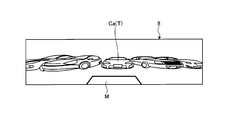
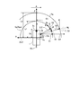
- FIG. 1 is a perspective view showing an example in which a part of a cabin of a vehicle equipped with a display control apparatus according to the embodiment is seen through.
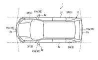
- FIG. 2 is a plan view (bird's-eye view) showing an example of a vehicle equipped with the display control apparatus according to the embodiment.
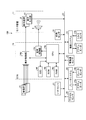
- FIG. 3 is a block diagram showing an example of the configuration of a display control system having the display control device according to the embodiment.
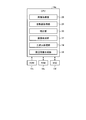
- FIG. 4 is an exemplary block diagram of a configuration of a CPU of the display control device according to the embodiment.
- FIG. 5 is an exemplary and schematic explanatory view showing the projection of a captured image on a virtual projection plane in the display control system according to the embodiment.
- FIG. 6 is an exemplary and schematic explanatory view showing a virtual projection plane (three-dimensional shape model) used in the display control apparatus according to the embodiment.
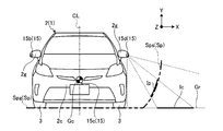
- FIG. 7 is a schematic and exemplary side view showing a vehicle shape model and a virtual projection plane provided with a bottom surface and a side surface in the display control system according to the embodiment.
- FIG. 8 is a schematic and exemplary side view showing a vehicle shape model and a virtual projection plane provided with only a side surface in the display control system according to the embodiment.
- FIG. 9 is a schematic and exemplary explanatory view illustrating calculation of a projection position and a correction factor of an image in the display control system according to the first embodiment.
- FIG. 10 is a schematic view showing a comparative example of three-dimensional display images when the correction is not performed in the display control system according to the first embodiment.
- FIG. 11 is a schematic view showing a display example of a three-dimensional display image when the correction in the display control system according to the first embodiment is performed.
- FIG. 12 is a diagram for explaining another method of calculating the correction factor in the display control system according to the first embodiment, and illustrates the intersection coordinates of the position coordinates of the imaging unit and the virtual projection plane and the intersection coordinates of the road surface.
- FIG. FIG. 13 is a diagram for explaining another calculation method of the correction factor in the display control system according to the first embodiment, and is an explanatory view for explaining an example of devising the correction factor using each coordinate of FIG. is there.
- FIG. 14 is a schematic and exemplary explanatory view illustrating calculation of a projection position and a correction factor of a front image in the display control system according to the second embodiment.
- FIG. 15 is a schematic and exemplary explanatory view illustrating calculation of a projection position and a correction factor of a side image in the display control system according to the second embodiment.
- FIG. 16 is a schematic diagram illustrating that, in the display control system according to the second embodiment, double projection occurs when the image is projected using a front image and a side image, and that double reflection can be reduced. And an illustrative illustration.
- FIG. 17 is a schematic view showing a comparative example of three-dimensional display images when the correction is not performed in the display control system according to the second embodiment.
- FIG. 18 is a schematic view illustrating a display example of a three-dimensional display image when the correction in the display control system according to the second embodiment is performed.
- FIG. 19 is a schematic view showing an example of a display deviation which may newly occur when the correction in the display control system according to the second embodiment is performed.
- FIG. 20 is an explanatory diagram for explaining an application example of the correction factor in the display control system according to the third embodiment.
- FIG. 21 is a schematic view showing a display example of a three-dimensional display image when the correction factor in the display control system according to the third embodiment is applied.
- FIG. 22 is an explanatory diagram of another application example of the correction factor in the display control system according to the fourth embodiment.
- FIG. 23 is a schematic view showing a display example of a three-dimensional display image when the correction factor in the display control system according to the fourth embodiment is applied.
- the vehicle 1 equipped with a display control device may be, for example, an automobile having an internal combustion engine (not shown) as a drive source, that is, an internal combustion engine automobile or an electric motor (not shown). It may be a car as a drive source, that is, an electric car or a fuel cell car. In addition, it may be a hybrid car using both of them as a driving source, or may be a car equipped with another driving source.
- the vehicle 1 can be mounted with various transmissions, and can be mounted with various devices necessary for driving an internal combustion engine or a motor, such as a system or components.
- a four-wheel drive vehicle can be used which transmits drive power to all four wheels 3 and uses all four wheels as drive wheels.
- the system, number, layout, and the like of the devices involved in the drive of the wheels 3 can be set variously.
- the drive system is not limited to the four-wheel drive system, and may be, for example, a front wheel drive system or a rear wheel drive system.
- the vehicle body 2 constitutes a passenger compartment 2 a in which a passenger (not shown) rides.
- a steering unit 4, an acceleration operation unit 5, a braking operation unit 6, a gear change operation unit 7 and the like are provided in the passenger compartment 2a in a state of facing the driver's seat 2b as a passenger.
- the steering unit 4 is, for example, a steering wheel protruding from the dashboard 24,
- the acceleration operation unit 5 is, for example, an accelerator pedal positioned under the driver's foot
- the braking operation unit 6 is, for example, the driver's It is a brake pedal located under the foot
- the shift operating unit 7 is, for example, a shift lever that protrudes from the center console.
- the steering unit 4, the acceleration operation unit 5, the braking operation unit 6, the shift operation unit 7, and the like are not limited to these.
- a display device 8 and an audio output device 9 are provided in the passenger compartment 2a.
- the display device 8 is, for example, a liquid crystal display (LCD), an organic electroluminescent display (OELD), or the like.
- the audio output device 9 is, for example, a speaker.
- the display device 8 is covered with a transparent operation input unit 10 such as a touch panel, for example. The occupant can visually recognize the image displayed on the display screen of the display device 8 through the operation input unit 10.
- an occupant operates the operation input unit 10 by touching or pushing or moving the operation input unit 10 with a finger or the like at a position corresponding to the image displayed on the display screen of the display device 8. It can be done.
- the display device 8, the audio output device 9, the operation input unit 10, and the like are provided, for example, in the monitor device 11 located at the center of the dashboard 24 in the vehicle width direction, that is, in the lateral direction.
- the monitor device 11 can have an operation input unit (not shown) such as a switch, a dial, a joystick, or a push button.
- an audio output device (not shown) can be provided at another position in the vehicle compartment 2a different from the monitor device 11, and audio is output from the audio output device 9 of the monitor device 11 and another audio output device. be able to.
- the monitor device 11 can also be used as, for example, a navigation system or an audio system.
- the vehicle 1 is, for example, a four-wheeled vehicle, and has two left and right front wheels 3F and two left and right rear wheels 3R. All of these four wheels 3 can be configured to be steerable.
- the vehicle 1 has a steering system 13 that steers at least two wheels 3.
- the steering system 13 has an actuator 13a and a torque sensor 13b.
- the steering system 13 is electrically controlled by an ECU 14 (electronic control unit) or the like to operate the actuator 13a.
- the steering system 13 is, for example, an electric power steering system, an SBW (steer by wire) system, or the like.
- the steering system 13 adds torque, that is, assist torque to the steering unit 4 by the actuator 13a to compensate for the steering force, or steers the wheel 3 by the actuator 13a.
- the actuator 13a may steer one wheel 3 or may steer a plurality of wheels 3.
- the torque sensor 13 b detects, for example, a torque that the driver gives to the steering unit 4.
- the vehicle body 2 is provided with, for example, four imaging units 15a to 15d as the plurality of imaging units 15.
- the imaging unit 15 is, for example, a digital camera that incorporates an imaging device such as a charge coupled device (CCD) or a CMOS image sensor (CIS).
- the imaging unit 15 can output moving image data (captured image data) at a predetermined frame rate.
- Each of the imaging units 15 has a wide-angle lens or a fish-eye lens, and can image a range of, for example, 140 ° to 220 ° in the horizontal direction.
- the optical axis of the imaging unit 15 may be set obliquely downward.
- the imaging unit 15 sequentially captures an environment around the outside of the vehicle 1 including a road surface or an object (for example, a tree, a person, a bicycle, a vehicle, etc. as an obstacle) on which the vehicle 1 can move.
- a road surface or an object for example, a tree, a person, a bicycle, a vehicle, etc. as an obstacle
- the imaging unit 15a (rear imaging unit) is located, for example, at the rear end 2e of the vehicle body 2 and provided on the lower wall of the rear window of the door 2h of the rear hatch. Take a backward image including the situation.
- the imaging unit 15b (right side imaging unit) is, for example, located at the right end 2f of the vehicle body 2, is provided on the right side door mirror 2g, and includes a right side image including the state of the area including the right side of the vehicle 1 Take an image.
- the imaging unit 15c (front imaging unit) is located, for example, on the front side of the vehicle body 2, that is, on the front end 2c in the front-rear direction of the vehicle, provided on the front bumper, the front grille, etc.
- the imaging unit 15d (left side imaging unit) is, for example, located at the left end 2d of the vehicle body 2 and provided on the left side door mirror 2g, the left side image including the state of the area including the left side of the vehicle 1 Take an image.
- the display control system 100 in addition to the ECU 14, the monitor device 11, the steering system 13, etc., the brake system 18, steering angle sensor 19, accelerator sensor 20, shift A sensor 21, a wheel speed sensor 22 and the like are electrically connected via an in-vehicle network 23 as a telecommunication line.
- the in-vehicle network 23 is configured, for example, as a controller area network (CAN).
- the ECU 14 can control the steering system 13, the brake system 18 and the like by transmitting control signals through the in-vehicle network 23.
- the ECU 14 detects detection results of the torque sensor 13b, the brake sensor 18b, the steering angle sensor 19, the accelerator sensor 20, the shift sensor 21, the wheel speed sensor 22, and operation signals of the operation input unit 10 etc via the in-vehicle network 23. Etc can be received.
- the ECU 14 has, for example, a CPU 14a (central processing unit), a ROM 14b (read only memory), a RAM 14c (random access memory), a display control unit 14d, an audio control unit 14e, an SSD 14f (solid state drive, flash memory) and the like. ing.
- the CPU 14a reads a program stored (installed) in a non-volatile storage device such as the ROM 14b, and executes arithmetic processing according to the program.
- the CPU 14a executes, for example, image processing related to an image displayed on the display device 8.
- the CPU 14a performs arithmetic processing and image processing on captured image data captured by the imaging unit 15 to generate a three-dimensional peripheral image (for example, an overhead image).
- the CPU 14a can change the viewpoint of the peripheral image to be generated.
- the RAM 14c temporarily stores various data used in the calculation in the CPU 14a.
- the display control unit 14d mainly performs composition of image data displayed on the display device 8 and the like in the arithmetic processing in the ECU 14.
- the voice control unit 14 e mainly performs processing of voice data output from the voice output device 9 among the calculation processing in the ECU 14.
- the SSD 14 f is a rewritable non-volatile storage unit, and can store data even when the power supply of the ECU 14 is turned off.
- the CPU 14a, the ROM 14b, the RAM 14c, and the like can be integrated in the same package.
- the ECU 14 may be configured to use another logical operation processor such as a DSP (digital signal processor) or a logic circuit instead of the CPU 14a.
- a hard disk drive (HDD) may be provided instead of the SSD 14f, and the SSD 14f and the HDD may be provided separately from the ECU 14.
- the brake system 18 enhances, for example, an anti-lock brake system (ABS) that suppresses the lock of the brake, an anti-slip device (ESC: electronic stability control) that suppresses the side-slip of the vehicle 1 at cornering, They are an electric brake system which performs a brake assist, BBW (brake by wire), etc.
- the brake system 18 applies a braking force to the wheel 3 and thus to the vehicle 1 via the actuator 18a.
- the brake system 18 can execute various controls by detecting the lock of the brake, the idle rotation of the wheel 3, the sign of a side slip, and the like from the difference in rotation of the left and right wheels 3.
- the brake sensor 18 b is, for example, a sensor that detects the position of the movable portion of the braking operation unit 6.
- the steering angle sensor 19 is a sensor that detects the steering amount of the steering unit 4 such as a steering wheel, for example.
- the ECU 14 acquires the steering amount of the steering unit 4 by the driver, the steering amount of each wheel 3 at the time of automatic steering, and the like from the steering angle sensor 19 and executes various controls.
- the accelerator sensor 20 is, for example, a sensor that detects the position of the movable portion of the acceleration operation unit 5.
- the shift sensor 21 is, for example, a sensor that detects the position of the movable portion of the shift operation unit 7.
- the wheel speed sensor 22 is a sensor that detects the amount of rotation of the wheel 3 and the number of rotations per unit time.
- the wheel speed sensor 22 outputs a wheel speed pulse number indicating the detected rotation speed as a sensor value.
- the ECU 14 calculates the amount of movement of the vehicle 1 and the like based on the sensor value acquired from the wheel speed sensor 22 and executes various controls.
- the CPU 14a included in the ECU 14 displays the environment around the vehicle 1 based on the captured image data captured by the imaging unit 15 as described above, for example, in a three-dimensional image.
- the CPU 14a includes various modules as shown in FIG.
- the CPU 14a includes, for example, an image acquisition unit 26, a projection plane acquisition unit 28, a correction unit 30, an image synthesis unit 32, a three-dimensional processing unit 34, a peripheral image generation unit 36, and the like. These modules can be realized by reading a program installed and stored in a storage device such as the ROM 14 b and executing the program.
- the image acquisition unit 26 acquires information necessary to display the surroundings of the vehicle 1. For example, the image acquisition unit 26 acquires a plurality of captured image data (for example, data such as a front image, a right side image, a left side image, and a rear image) from a plurality of imaging units 15 that capture the periphery of the vehicle 1 .
- a plurality of captured image data for example, data such as a front image, a right side image, a left side image, and a rear image
- the projection plane acquisition unit 28 acquires, for example, a three-dimensional shape model stored in advance in the ROM 14 b, the SSD 14 f, or the like.
- the three-dimensional shape model is, for example, data defining a virtual projection plane surrounding the periphery of the vehicle 1.
- 5 to 7 show an example of the three-dimensional shape model.
- FIG. 5 is a schematic view showing an example of projecting a captured image Ic captured by the imaging unit 15 d (left side imaging unit) on a virtual projection plane Sp including the bottom surface Spg and the side surface Sps.
- 6 is a view schematically showing the configuration of the virtual projection plane Sp
- FIG. 7 is a view schematically showing the entire shape of the virtual projection plane Sp.
- the virtual projection plane Sp has a bottom surface Spg along the ground Gr and a bottom surface Spg, that is, a side surface Sps rising from the ground Gr.
- the ground Gr is a horizontal surface orthogonal to the height direction Y (vertical direction) of the vehicle 1 and is also a contact surface of the wheel 3.
- the bottom surface Spg is, for example, a substantially circular flat surface, and is a horizontal surface based on the vehicle 1.
- the side surface Sps is, for example, a curved surface that is in contact with the bottom surface Spg and rises in the height direction from a portion of the bottom surface Spg and surrounds a portion of the bottom surface Spg. As shown in FIG.
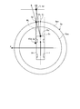
- the shape of the vertical imaginary cross section of the vehicle 1 passing through the center Gc of the vehicle 1 on the side surface Sps is, for example, elliptical or parabolic.
- the side surface Sps is configured, for example, as a rotational surface around a center line CL that passes through the center Gc of the vehicle 1 and extends in the height direction of the vehicle 1. That is, the side surface Sps surrounds the periphery of the vehicle 1.
- the virtual projection plane Sp which is a three-dimensional shape model, rises from the bottom surface Spg, for example, in the case of a projection plane on which the virtual projection plane Sp projects a front image showing mainly a front situation of the vehicle 1 It includes a side surface SpsF for projecting an image, a side surface SpsR for projecting a right side image, and a side surface SpsL for projecting a left side image.
- the virtual projection plane Sp is data of a mesh structure in which coordinates (X, Y, Z) are defined, and data of each pixel of captured image data captured by the imaging unit 15 is, for example, a mesh intersection point (coordinates X, Y, Projected on the intersection point defined by Z).
- the mesh of virtual projection surface Sp shown in FIG. 6 is shown in figure for description, It is set so that it can not actually visually recognize.
- the correction unit 30 projects the image (display target image) captured by the imaging unit 15 acquired by the image acquisition unit 26 on the virtual projection plane Sp
- the size of the object displayed in the imaging direction is A correction is made to eliminate inconveniences such as unnatural reduction in size and rapid narrowing of the road width.
- correction is performed such that the projected image spreads in the width direction.
- the imaging unit 15 c is installed at, for example, a substantially central portion in the vehicle width direction of the vehicle 1. That is, the imaging unit 15c obliquely views other than the imaging target existing in front of the imaging unit 15c, for example, an object on the imaging center line extending in the imaging direction of the imaging unit 15c.
- the image captured by the imaging unit 15c is projected at a position where a straight line connecting an object to be captured and the imaging unit 15c intersects the virtual projection plane Sp.
- the object on the imaging center line it is projected to a position closer to the imaging center line than the actual position on the virtual projection plane Sp. Therefore, as described above, the size of the displayed object may be unnaturally reduced (compressed toward the imaging center line) or the road width of the road may be narrowed sharply. Therefore, the correction unit 30 performs correction so as to reduce the unnatural display as described above.
- the image to be displayed, which is at least one, is corrected.
- a straight line extending from the imaging unit 15c or the imaging unit 15a in the first direction which is the vehicle length direction of the vehicle 1 is taken as a first virtual straight line.
- the coordinate corresponding to the position where the first virtual straight line intersects with the virtual projection plane Sp is taken as the first coordinate.
- a straight line that is separated from the first virtual straight line in the vehicle width direction of the vehicle 1 and extends in the first direction is taken as a virtual reference line.
- the virtual reference line can be set, for example, to extend in the first direction along the left side surface or the right side surface of the vehicle body 2 of the vehicle 1. Then, a coordinate corresponding to a position where the virtual reference line intersects with the virtual projection plane Sp is taken as a second coordinate.
- the correction unit 30 performs correction such that the projection position of the display target image is changed in the second direction from the first coordinate toward the second coordinate. Details of the correction of the projection position will be described later.
- the lens with which the imaging part 15 is equipped may be a wide angle lens or a fisheye lens in order to implement
- the image combining unit 32 includes, for example, captured image data of a forward image captured by the imaging unit 15c acquired by the image acquisition unit 26 and corrected by the correction unit 30, captured image data of a right-side image captured by the imaging unit 15b,
- the captured image data of the left side image captured by the imaging unit 15d are connected by combining them at their boundary portions, and one captured image data is generated.
- combining the captured image data of the forward image with the captured image data of the right side image, and combining the captured image data of the forward image with the captured image data of the left side image combining the boundary part as it is is the boundary.
- the lines may appear clearly.
- the brightness and the color of the image may be different depending on whether or not the front image captured by the imaging unit 15c and the right side image captured by the imaging unit 15b are hit by sunlight or light.
- boundaries due to differences in brightness and color tone may appear, and the quality of an image based on one synthesized image data may be degraded. Therefore, as shown in FIG. 6, the horizontal projection of captured image data of the front image onto the virtual projection surface Sp and the horizontal image of the side SpsR onto which the captured image data of the right side image is projected An overlapping area LA overlapping with the end is set.
- the image combining unit 32 may execute blending processing of combining images using a% of each of the captured image data of the forward image and the captured image data of the right side image.
- the front image and the right side image are synthesized so as to gradually change, and it is possible to make the boundary line generated due to the difference in the brightness and the hue inconspicuous.
- the boundary line can be made less noticeable in the entire synthesized peripheral image.
- the image combining unit 32 similarly picks up the captured image data of the rear image captured by the imaging unit 15a and the right side captured by the imaging unit 15b.
- the captured image data of the image and the captured image data of the left side image captured by the imaging unit 15 d are combined to generate one captured image data.
- the three-dimensional processing unit 34 performs image synthesis on a virtual projection plane Sp (three-dimensional shape model) which is defined based on the position where the vehicle 1 is present, surrounding the vehicle 1 or being a part of the periphery. Data of a virtual projection image is generated by projecting the captured image data synthesized by the unit 32. As shown in FIG. 5, the three-dimensional processing unit 34 calculates a virtual projection image Ip obtained by projecting the captured image Ic on a virtual projection plane Sp. When the photographed image Ic is projected on the ground Gr, the image may become longer as it goes away from the imaging unit 15, and may appear longer than the actual length in the output image. As can be seen from FIG. 5, the virtual projected image Ip projected onto the side surface Sps rising from the ground Gr (bottom surface Spg) has a shorter image than when projected onto the ground Gr, and the actual image in the output image It is suppressed that it appears longer than the length.
- a virtual projection plane Sp three-dimensional shape model
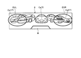
- the three-dimensional processing unit 34 is a vehicle shape model corresponding to the vehicle 1 stored in the ROM 14 b or the SSD 14 f in a three-dimensional virtual space including the virtual projection plane Sp. Arrange M.
- the three-dimensional processing unit 34 sets a predetermined transmittance to the vehicle shape model M disposed in the three-dimensional virtual space. Thereby, in the three-dimensional virtual space, the virtual projected image Ip on the opposite side can be visually recognized through the vehicle shape model M.
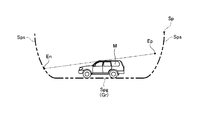
- the peripheral image generation unit 36 sets, in the three-dimensional virtual space, the virtual projection image Ip and the vehicle shape model M projected on the virtual projection plane Sp in the three-dimensional virtual space on which the captured image data is projected. It generates surrounding image data when looking at the gaze point En from the viewpoint Ep.
- the peripheral image generation unit 36 supplies the generated peripheral image data to the display control unit 14 d, and the display control unit 14 d causes the display device 8 to display a three-dimensional peripheral image.
- the display control system 100 can also display a three-dimensional peripheral image only with the imaging unit 15c (front imaging unit). Similarly, the display control system 100 displays a three-dimensional peripheral image only with the imaging unit 15a (backward imaging unit), only the imaging unit 15b (rightward imaging unit), and only the imaging unit 15d (leftward imaging unit). be able to. In this case, the processing of the image combining unit 32 is omitted.
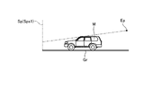
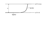
- FIG. 8 is a conceptual schematic view showing another embodiment of the virtual projection plane Sp when only the imaging unit 15c is used.
- the virtual projection plane Sp shown in FIG. 8 includes only the side surface Sps1 that stands vertically from the ground Gr a predetermined distance ahead of the vehicle shape model M disposed on the ground Gr.
- the virtual projection image Ip generated by the peripheral image generation unit 36 and the vehicle shape model M can be displayed similarly to the virtual projection surface Sp having the bottom surface Spg and the side surface Sps shown in FIG. It is possible to provide the user with a three-dimensional projection image based on surrounding image data when viewing the gaze point En from the viewpoint Ep set in the original virtual space.
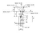
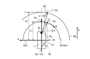
- FIG. 9 is a projection position in the case of projecting a front image (display target image) captured by the imaging unit 15c (front imaging unit: processing target imaging unit) on a virtual projection plane Sp having only the side surface Sps1 as shown in FIG.
- FIG. 6 is a schematic and exemplary explanatory view for explaining the occurrence of a deviation phenomenon and the calculation of a correction factor for suppressing the deviation phenomenon.
- the imaging unit 15c front imaging unit: processing target imaging unit
- the imaging unit 15c is installed on the vehicle center line OL1 extending in the vehicle length direction (front-rear direction) of the vehicle 1
- a straight line extending in the first direction A, which is the vehicle length direction, from the imaging unit 15c along the vehicle center line OL1 is taken as a first virtual straight line Q1.
- the imaging center line of the imaging unit 15c is an example of a first virtual straight line Q1 extending from the imaging unit 15c in the first direction A, which is the vehicle length direction of the vehicle 1.
- the first virtual straight line Q1 extends in the first direction A parallel to the ground contact surface (ground Gr) of the vehicle 1 from the imaging unit 15c, as an example. Then, it is assumed that the virtual projection plane Sp (side surface Sps, Sps1) is set at a position separated by a predetermined distance L1 from the imaging unit 15c in the direction of the first direction A (first virtual straight line Q1). Further, the virtual reference surface Rp is located at a position further away in front of the virtual projection surface Sp by a predetermined distance L2 (predetermined distance) from the imaging unit 15c in the first direction (first virtual straight line Q1). It shall be set.
- a position where the first virtual straight line Q1 and the virtual projection plane Sp intersect is set as a first coordinate point S1 (X1, Y1, Z1). Further, as described above, a straight line that is separated from the first virtual straight line Q1 in the vehicle width direction of the vehicle 1 and extends in the first direction A is taken as a virtual reference line RL.
- the virtual reference line RL is a vertical plane passing through the door mirror 2g provided on the side surface of the vehicle 1 in a position overlapping with either the left or right imaging unit (imaging unit 15b or imaging unit 15d) in the vehicle width direction.
- the virtual reference line RL may be set, for example, at a predetermined distance W from the vehicle center line OL1, for example, at a distance of at least half the vehicle width W0 (W0 / 2) outside the vehicle center line OL1 outside the vehicle width direction. it can. Then, a position at which the virtual reference line RL intersects with the virtual projection plane Sp is set as a second coordinate point S2 (X2, Y2, Z2). Further, it can be set to extend in the first direction A. Then, a position at which the virtual reference line RL intersects with the virtual reference surface Rp is taken as a third coordinate point S3 (X3, Y3, Z3).
- FIG. 9 consider a case where an object T present at the position of the virtual reference surface Rp, that is, an object present farther from the virtual projection surface Sp is projected onto the virtual projection surface Sp.
- the position at which the object T intersects the virtual reference line RL and the virtual reference surface Rp (third coordinate point) is an example in which the change of the display position in the case of projecting the object T onto the virtual projection surface Sp is easy to understand.
- S3 X3, Y3, Z3
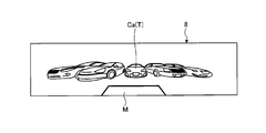
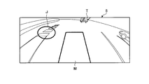
- FIG. 10 is a three-dimensional projection image as a comparative example displayed on the display device 8 when the correction by the correction unit 30 is not performed.
- the vehicle Ca (object T) displayed so as to exist ahead of the host vehicle (vehicle shape model M) is compressed toward the first virtual straight line Q1 (imaging center line: see FIG.
- the size of the vehicle Ca may be erroneously recognized, and, for example, when the vehicle Ca is to park the vehicle in the empty space after leaving the vehicle, the vehicle Ca is displayed on the display device 8.
- the display may be made so that the space in which the vehicle 1 was present looks narrow, so it may be difficult for the driver of the vehicle 1 (own vehicle) to determine whether or not parking is possible.
- the road width may be displayed so as to be sharply narrowed, which may give the driver a sense of discomfort.
- the fourth coordinate point S4 (X4, Y4, Z4) on the virtual projection plane Sp is projected to the second coordinate point S2 (X2, Y2, Z2) on the virtual projection plane Sp. If correction is performed, the unnatural projection as described above is reduced. That is, for the image projected to the right of the first virtual straight line Q1 (imaging center line), as shown in FIG.
- the correction unit 30 sets the first virtual straight line Q1 with respect to the imaging unit 15c and the virtual projection plane Sp From a first coordinate point S1 (X1, Y1, Z1) corresponding to the position where the point intersects to a second coordinate point S2 (X2, Y2, Z2) where the virtual reference line RL intersects the virtual projection plane Sp
- the correction factor ⁇ of the coordinates may be calculated so as to correct the projection position of the image in the direction B of FIG.
- a correction factor ⁇ of coordinates may be obtained so as to correct the projection position of the image in the direction opposite to the second direction B. Note that the left and right correction factors ⁇ can be made the same across the first virtual straight line Q1, so in the following description, only one side will be described.
- a three-dimensional composite image in which the projection position of the front image captured by the imaging unit 15c is corrected using the correction factor ⁇ obtained in this manner is shown in FIG.
- the correction unit 30 calculates two-dimensional coordinates (U, V) of the forward image corresponding to the corrected coordinates ( ⁇ X, Y, Z) on the virtual projection plane Sp defined by the three-dimensional shape model based on the correction factor ⁇ . Get an image. Then, they are projected on the coordinates (X, Y, Z) on the virtual projection plane Sp. As a result, as shown in FIG.
- the vehicle Ca (object T) displayed so as to exist ahead of the own vehicle is based on the first virtual straight line Q1 (imaging center line) It is extended to the left and right, and is displayed in a size where discomfort is reduced compared to the own vehicle (vehicle shape model M).
- the image on the right of the first virtual straight line Q1 extends in the second direction B
- the image on the left of the first virtual straight line Q1 extends in the opposite direction to the second direction B.
- the parking space on the display device 8 is compared with the vehicle (vehicle shape model M)
- vehicle vehicle shape model M
- the display is performed with a reduced sense of incongruity, and the driver of the vehicle 1 (self-vehicle) can easily determine whether parking is possible.
- the change in the road width of the road extending in the first direction A (forward) becomes gentle, which makes it difficult for the driver to feel discomfort.
- the display device A driver who visually recognizes the three-dimensional composite image displayed on 8 easily recognizes the positional relationship between the vehicle and the object T.
- the first imaginary straight line Q1 extends from the front imaging unit (imaging unit 15c) in the first direction A in parallel with the ground surface (ground Gr) of the vehicle 1.
- the virtual reference line RL is located at a position overlapping with either the left or right imaging unit (imaging unit 15b or imaging unit 15d) in the vehicle width direction, and the height at which the front imaging unit (imaging unit 15c) is provided It extends in the first direction A in parallel with the ground contact surface (ground Gr).
- the first virtual straight line Q1 and the virtual reference line RL are spaced apart in the vehicle width direction and extend in parallel to each other in the first direction A when viewed from vertically above, from the side of the vehicle 1 When viewed, it extends to be visible overlapping.
- the coordinates in the height direction become equal at the first coordinate point S1 to the fourth coordinate point S4. Therefore, when calculating the correction factor ⁇ using the first distance and the second distance (Equation 1 to Formula 3), stable acquisition of the correction factor ⁇ and the correction factor are not affected by the coordinate in the height direction. Stable correction using ⁇ can be realized.
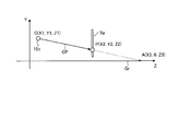
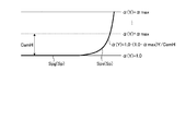
- FIG. 12 and 13 illustrate another method of calculating the correction factor ⁇ .
- coordinates C (X1, Y1, Z1) are positions of the imaging unit 15c.
- coordinates P (X2, Y2, Z2) are arbitrary points on the virtual projection plane Sp.
- Coordinates A (X3, 0, Z3) are intersections of the straight line CP and the ground Gr.
- a straight line CP passing through the coordinates C and the coordinates P can be represented by the following equation (vector equation).
- t is a parameter.
- a coordinate A on the ground Gr which is an extension of the straight line CP shown in FIG. 12, is obtained.
- the image projected on the coordinates P on the virtual projection plane Sp is an image corresponding to the coordinates A.
- the correction factor ⁇ for projecting the object T present on the virtual reference line RL onto the coordinates P on the virtual projection plane Sp is the first virtual straight line Q1 ( It can be determined by the relationship between the distance W from the vehicle center line OL1) to the virtual reference line RL and the coordinate X3 of the coordinate A.
- the virtual projection plane Sp is an upright plane in front of the vehicle and the three-dimensional composite image is displayed on the display device 8 using only the front image captured by the imaging unit 15c (front imaging unit).
- the display such as the situation in front (other cars, roads, etc.) being displayed unnaturally small or the road width rapidly narrowing is reduced.
- a three-dimensional composite image indicating the situation behind can be generated similarly using the rear image captured by the imaging unit 15a (rear imaging unit), and similarly grasping the surrounding situation centered on the rear of the vehicle Can be more appropriately recognized by the driver without discomfort.
- the correction unit 30 calculates the correction factor ⁇ for the imaging unit 15c every time the ignition switch is turned on, stores the correction factor ⁇ in, for example, the RAM 14c, and corrects the projection position of each image every time a three-dimensional composite image is generated. You can do so.
- FIG. 14 is a schematic and exemplary explanatory view for explaining the calculation of the projection position and the correction rate of the front image according to the second embodiment.
- the shape of the virtual projection plane Sp set in front of the vehicle 1 (own vehicle) is, for example, a curved surface centered on the vehicle center 1 a of the vehicle 1.
- the other configuration is the same as the configuration shown in FIG. 9 of the first embodiment, and the same configuration is denoted by the same reference numeral and the detailed description thereof is omitted.
- the distance L1 to the virtual projection plane Sp and the distance L2 to the virtual reference surface Rp are defined on the basis of a center line OL2 extending in the vehicle width direction passing through the vehicle center 1a of the vehicle 1.
- the virtual reference line RL (along the end 2 f which is the side surface of the vehicle 1 and extends in the first direction A) by the distance W from the first virtual straight line Q1 (imaging center line) in the vehicle width direction A straight line at spaced positions is defined.
- the first virtual straight line Q1 may be set to extend in the first direction A in parallel with the ground contact surface (ground Gr) of the vehicle 1 from the front imaging unit (the imaging unit 15c).
- the virtual reference line RL is located at a position overlapping with either the left or right imaging unit (imaging unit 15b or imaging unit 15d) in the vehicle width direction, and the height at which the front imaging unit (imaging unit 15c) is provided It may be set to extend in the first direction A in parallel with the ground surface (ground Gr) of 1.
- the third coordinate of the object T present at the intersection of the virtual reference surface Rp imaged by the imaging unit 15c and the virtual reference line RL when the correction by the correction unit 30 is not performed In the image corresponding to the point S3, a second virtual straight line Q2 (extension line) extending from the imaging unit 15c fixed at the center of the front end 2c of the vehicle 1 to the object T intersects with the virtual projection plane Sp It is projected to four coordinate points S4. Therefore, similarly to the case described in FIG. 9, the vehicle Ca (object T) displayed so as to exist in front of the vehicle 1 (vehicle shape model M) is set to the first virtual straight line Q1 (imaging center line) It is compressed towards you and appears to look smaller.
- the correction unit 30 calculates the correction factor ⁇ f for the front image, and based on this correction factor ⁇ f, a virtual defined by the three-dimensional shape model.
- An image of the two-dimensional coordinates (U, V) of the forward image corresponding to the corrected coordinates ( ⁇ fX, Y, Z) on the projection plane Sp is acquired. Then, they are projected on the coordinates (X, Y, Z) on the virtual projection plane Sp.
- the ratio between the line OL1) and the distance W (second distance) from the virtual reference line RL corrects the projection position in the second direction B (direction from the first coordinate point S1 to the second coordinate point S2)
- ⁇ f (L2-L1) / L2 formula 3f
- the correction factor ⁇ f can be easily defined from the distance L1 to the virtual projection plane Sp and the distance L2 to the virtual reference surface Rp based on the position of the imaging unit 15c.
- the vehicle Ca (object T) displayed so as to be present ahead of the own vehicle (vehicle shape model M) is the first as in FIG. It is extended to the left and right based on the virtual straight line Q1 (imaging center line), and is displayed in a size where discomfort is reduced compared to the own vehicle (vehicle shape model M).
- the change in the width of the road extending forward becomes gentle, which makes it difficult for the driver to feel discomfort.
- the heights of the first virtual straight line Q1 and the virtual reference line RL can be set to coincide with each other, and the first coordinate point S1 to the fourth coordinate point S4 can be set. Coordinates in the height direction can be made equal. Therefore, when calculating the correction factor ⁇ f using the first distance and the second distance (formula 1f to formula 3f), stable acquisition of the correction factor ⁇ f and the correction factor are not affected by the coordinate in the height direction. Stable correction using ⁇ f can be realized.
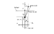
- FIG. 15 shows the correction factor ⁇ s in the case of generating a three-dimensional composite image showing the situation on the right side using the right side image (display target image) captured by the imaging unit 15b (right side imaging unit: processing target imaging unit) It is typical and an explanatory explanatory view explaining calculation of.
- the configuration of FIG. 14 is the same as that of FIG. 14 except that the imaging unit 15 b (right side imaging unit) is used instead of the imaging unit 15 c (front imaging unit). I omit it.
- the imaging unit 15 b (right-side imaging unit) may be installed vertically downward at the end 2 f of the vehicle 1.
- the imaging center line of the imaging unit 15b is directed vertically downward, when using a side image as a display target image as in the second embodiment, the imaging image of the captured image captured by the wide-angle lens or the fisheye lens
- the peripheral area is mainly used.
- the imaging unit 15 b rightward imaging unit
- the vehicle width direction of the vehicle 1 from the imaging unit 15 b is set to the first direction A.
- a straight line extending from the imaging unit 15b in the first direction A is taken as a first virtual straight line Q1.
- the first virtual straight line Q1 may be set to extend in the first direction A in parallel with the ground contact surface (ground Gr) of the vehicle 1 from the imaging unit 15b.
- a position where the first virtual straight line Q1 and the virtual projection plane Sp intersect is set as a first coordinate point S1.
- the virtual reference line RL is on a vertical plane passing through a position (front end 2c of the vehicle 1 in front of the vehicle 1) overlapping with the front imaging unit (imaging unit 15a) in the vehicle length direction.
- the height equal to the height at which the right side imaging unit (imaging unit 15b) is provided, and is set to extend in the first direction A in parallel with the ground surface (ground Gr) of the vehicle 1). It may be done.
- the position of the imaging unit 15b (right side imaging unit) is defined by the distance As from the center line OL2.
- the second coordinate point S2 is defined by the distance Bs from the vehicle center line OL1
- the third coordinate point S3 is defined by the distance Cs from the vehicle center line OL1.
- the position of the virtual reference surface Rp is defined by the distance Ds from the center line OL2.
- the correction unit 30 does not perform the correction on the object T present on the virtual reference surface Rp.
- a second virtual straight line Q2 extension line directed from the imaging unit 15b fixed to the door mirror 2g of the vehicle 1 to the object T intersects with the virtual projection surface Sp (Sps) It is projected to four coordinate points S4. Therefore, the vehicle Ca (object T) displayed so as to be present on the right side of the vehicle 1 (vehicle shape model M), as in the case described with FIGS. Is compressed and displayed to look small.
- the road width in the first direction A (the side of the vehicle) does not change
- the road width may be displayed so as to be sharply narrowed, which may give the driver a sense of discomfort.
- the correction unit 30 calculates the correction factor ⁇ s for the right side image, and based on the correction factor ⁇ s, the correction coordinates ( ⁇ sX, Y, Z) on the virtual projection plane Sp defined by the three-dimensional shape model The image of the two-dimensional coordinates (U, V) of the right side image corresponding to is acquired. Then, they are projected on the coordinates (X, Y, Z) on the virtual projection plane Sp.
- the correction factor ⁇ s can be easily defined from the distance L1 to the virtual projection surface Sp and the distance L2 to the virtual reference surface Rp with reference to the center line OL2.
- the vehicle (object T) displayed so as to be present to the right of the own vehicle (vehicle shape model M) in the three-dimensional composite image corrected using the correction factor ⁇ s is based on the first virtual straight line Q1. It is stretched back and forth, and is displayed in a size where discomfort is reduced compared to the own vehicle (vehicle shape model M). Further, the change in the road width of the road extending to the right of the vehicle 1 becomes gentle, which makes it difficult for the driver to feel discomfort. Moreover, when a pedestrian etc. exist, it displays on the position near an actual.
- the heights of the first virtual straight line Q1 and the virtual reference line RL can be set to coincide with each other, and the coordinates in the height direction at the first coordinate point S1 to the fourth coordinate point S4. Can be equal. Therefore, when calculating the correction factor ⁇ s using the first distance and the second distance (formula 1s to formula 3s), the acquisition of the stable correction factor ⁇ s and the correction factor are not affected by the coordinate in the height direction. Stable correction using ⁇ s can be realized.
- the virtual reference line RL is set along the first direction A at the rear end 2e (rear surface of the vehicle body) of the vehicle 1 for a region behind the first virtual straight line Q1 based on the imaging unit 15b. If so, it is possible to perform correction to reduce discomfort as well.
- the installation direction of the imaging unit 15b (imaging unit 15d) is not the vertical direction, but faces sideward like the imaging unit 15c, the imaging unit 15b faces rightward (leftward) as the first virtual straight line Q1.
- the first coordinate point S1 can be defined using the imaging center line of (imaging unit 15d).
- the image combining unit 32 can connect the images captured by the respective imaging units 15 to generate a three-dimensional composite image indicating a wider area. For example, an image in which the right side image and the left side image are connected to the left and right of the front image can be synthesized. Also in this case, when the correction by the correction unit 30 is not performed, an unnatural image may be displayed.
- the imaging unit 15 c disposed at the front end 2 c of the vehicle 1 and the imaging unit 15 d disposed at the door mirror 2 g on the left side of the vehicle 1 Think about the case.
- FIG. 16 illustrates an example of projecting a three-dimensional composite image using a virtual projection plane Sp configured by a bottom surface Spg and a side surface Sps as shown in FIG. 7 as another projection example of an image.
- FIG. 16 shows the case where the object T is present at a position farther from the virtual projection plane Sp (side surface Sps), and in the case of combining the forward image captured by the imaging unit 15c and the left side image captured by the imaging unit 15d. is there.
- the object T is assumed to be on a virtual reference line RL extending along the left end 2 d of the vehicle 1.
- the imaging unit 15d is installed at a position close to the virtual reference line RL, the two-dimensional coordinates (U, V) corresponding to the third coordinate point S3 of the object T shown in the image captured by the imaging unit 15d.
- Is projected on a virtual projection plane Sp (side surface Sps) it is projected to coordinates (small deviation in projection) substantially corresponding to the position (true position) where the object T exists. For example, it is projected to the second coordinate point S2.
- FIG. 17 is an example of a three-dimensional composite image displayed on the display device 8 when the correction by the correction unit 30 is not performed.
- the same vehicle Ca1 (object T) is doubly displayed in the joint area DVL of the imaging unit 15c (front imaging unit) and the imaging unit 15d (left side imaging unit) among the three-dimensional composite image.
- the same vehicle Ca2 (object T) is doubly displayed around the joint area DVR between the imaging unit 15c (front imaging unit) and the imaging unit 15b (right side imaging unit).
- the vehicle Ca displayed so as to be present in front of the own vehicle is displayed so as to be small as in the example shown in FIG. ing.
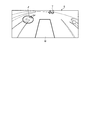
- FIG. 18 is a display example when the three-dimensional composite image subjected to the correction by the correction unit 30 is displayed on the display device 8.
- the object T in the display target image on the side captured by the imaging unit 15 d (left side imaging unit) is generally projected to the true position when projected onto the virtual projection plane Sp. Therefore, the correction unit 30 does not perform the correction.
- the correction unit 30 performs correction only in the X direction with respect to the display target image captured by the imaging unit 15c (front imaging unit).
- the two-dimensional coordinates (U, V) corresponding to the third coordinate point S3 of the object T shown in the display target image captured by the imaging unit 15c (front imaging unit) It is corrected in the direction from the coordinate point S1 to the second coordinate point S2.
- the image (object T) captured by the imaging unit 15c (front imaging unit) is the third coordinate point S3 of the object T in the display target image captured in the side captured by the imaging unit 15d (left side imaging unit) Are corrected so as to approach the projected position (second coordinate point S2). In other words, the projected position approaches and the double reflection is reduced (not noticeable).
- the vehicle Ca1 in the junction region DVL and the vehicle Ca2 in the junction region DVR are displayed more clearly (in the case of FIG. 18, a state in which double reflection is eliminated as an example is shown).
- the correction in the X direction is performed on the image captured by the imaging unit 15c (front imaging unit), so that the image is displayed in front of the own vehicle (vehicle shape model M) as in the example illustrated in FIG.
- the obtained vehicle Ca is displayed in a size in which the discomfort is reduced as compared with the own vehicle (vehicle shape model M).
- the virtual projection surface Sp is a curved surface shape surrounding the vehicle, and the imaging unit 15c (front imaging unit), imaging unit 15d (left side imaging unit), imaging unit 15b
- the imaging unit 15c front imaging unit
- imaging unit 15d left side imaging unit
- imaging unit 15b imaging unit 15b
- unnaturalness of display can be reduced. That is, while making double reflection inconspicuous, the display such as the situation in front of the own vehicle (other vehicles, roads, etc.) being displayed unnaturally small or the road width becoming narrow sharply is reduced.
- the three-dimensional composite image displayed on the display device 8 it becomes easier for the driver to more appropriately recognize the situation of the surroundings around the front of the own vehicle without a sense of discomfort.
- the same effect can be obtained when connecting the display target image captured by the imaging unit 15c and the display target image captured on the right side captured by the imaging unit 15b. Further, the same applies to the case where the display target image captured by the imaging unit 15a and the side display target image captured by the imaging unit 15b (the imaging unit 15d) are connected, and similar effects can be obtained. Also in this case, as described in the first embodiment, settings can be made to make the heights of the first virtual straight line Q1 and the virtual reference line RL coincide with each other, and the first coordinate point S1 to the fourth coordinate point In S4, the coordinates in the height direction can be made equal. Therefore, when calculating the correction factor ⁇ using the first distance and the second distance (Equation 1 to Formula 3), stable acquisition of the correction factor ⁇ and the correction factor are not affected by the coordinate in the height direction. Stable correction using ⁇ can be realized.
- Embodiment 3 When the virtual projection surface Sp is configured by the bottom surface Spg and the side surface Sps as in the example illustrated in FIG. 16, as described above, when the correction unit 30 corrects the virtual projection surface Sp (side surface Sps), the bottom surface Spg Image deviation may occur at the boundary between the and the side surface Sps. For example, when a correction is made to extend in the vehicle longitudinal direction using the correction factor ⁇ s for the left side image, the influence of the correction in the side surface Sps portion appears notably. As an example, as shown in FIG. 19, a phenomenon occurs in which the white line of the road surface deviates at the boundary ja of the bottom surface Spg and the side surface Sps of the portion indicated by the region J.
- the maximum ( ⁇ max) is set.
- the maximum correction factor ⁇ max is the correction factor ⁇ calculated in the first and second embodiments.
- the correction factor ⁇ (Y) at the height Y can be expressed by the equation 6 shown below.
- FIG. 21 shows a three-dimensional composite image in which the correction unit 30 corrects the projection position of the left side image captured by the imaging unit 15d using the correction factor ⁇ (Y).
- the correction unit 30 determines a two-dimensional coordinate of the left side image corresponding to the corrected coordinate ( ⁇ (Y) X, Y, Z) on the side surface Sps defined by the three-dimensional shape model based on the correction factor ⁇ (Y).
- the side surface Sps is gradually corrected from the bottom surface Spg, and the bottom surface Spg and the side surface Sps are smoothly connected to generate a three-dimensional composite image in which the image deviation is not noticeable can do.
- the three-dimensional composite image displayed on the display device 8 it becomes easier for the driver to more appropriately recognize the situation of the surroundings around the front of the own vehicle without a sense of discomfort.
- the front image captured by the imaging unit 15c front imaging unit
- the correction factor ⁇ (Y) the image shift at the boundary between the bottom surface Spg and the side surface Sps becomes inconspicuous, making the user uncomfortable. Not three-dimensional composite image can be displayed.
- the image deviation at the boundary between the bottom surface Spg and the side surface Sps can be reduced, but the maximum correction factor ⁇ max is obtained at the upper end of the side surface Sps.
- the inclination of the displayed object T may increase as it approaches the top of the side surface Sps.
- the object T (vehicle) displayed on the right of the front of the own vehicle (vehicle shape model M) is displayed inclined to the right.
- the height CamH of the imaging unit 15 is set as the maximum correction factor ⁇ max, as shown in FIG.
- the correction factor ⁇ (Y) is determined so as to maintain (fix) the maximum correction factor ⁇ max up to the upper end of the side surface Sps.
- Correction factor ⁇ (Y) 1.0-(1.0- ⁇ max) Y / Cam H Formula 7
- the maximum correction factor ⁇ max is maintained at or above the height CamH of the imaging unit 15
- the projected object T is not inclined at a portion above the height CamH of the imaging unit 15 of the side surface Sps.
- the object T, the whole of which is inclined to the right is suppressed in the middle, as shown in FIG. 23, and the inclination of the object T as a whole becomes inconspicuous. The discomfort of the image is further reduced.
- a front image taken by the imaging unit 15c is taken as a main image (central display image), and a side image taken by the imaging unit 15b or the imaging unit 15d is joined to the side to make a three-dimensional composite.
- An example of generating an image is shown.
- a side image captured by the imaging unit 15b or the imaging unit 15d is used as a main image (central display image), and a front image captured by the imaging unit 15c or a rear image captured by the imaging unit 15a It may be connected to generate a three-dimensional composite image, and the same effect can be obtained.
- the correction unit 30 calculates the correction factor for each imaging unit 15 and stores the correction factor in the RAM 14c or the like each time the ignition switch is turned on.
- the position is fixed at a vehicle manufacturing plant, a dealer, or the like, and thereafter, it is generally not changed except for repair, replacement of the imaging unit 15 and the like. Therefore, the correction factor ⁇ for each imaging unit 15 is calculated in advance in a manufacturing plant, dealer, or the like, and the three-dimensional coordinates ( ⁇ X, Y, Z) of the point S used when correcting the projection position of the image is calculated.
- Two-dimensional coordinates (U, V) may be stored in the ROM 14 b or the SSD 14 f. In this case, the processing load on the ECU 14 is reduced, and the use of the relatively low-performance ECU 14 becomes possible, and the selection range for selecting the ECU 14 is expanded, and the use of the low-cost ECU 14 becomes possible. is there.
Abstract
車両の前方画像および後方画像の少なくとも一方である、表示対象画像を取得する画像取得部と、車両の接地面から高さ方向に立ち上がる側面を少なくとも備える三次元の仮想投影面を取得する投影面取得部と、画像取得部が取得した表示対象画像を仮想投影面に投影する場合に、表示対象画像を撮像した前方撮像部または後方撮像部から車両の車長方向である第一の方向に延びる第一の仮想直線と仮想投影面とが交わる位置に対応する第一の座標から、第一の仮想直線から車両の車幅方向に離間して第一の方向に延びる仮想基準線と仮想投影面とが交わる位置に対応する第二の座標に向かう第二の方向に表示対象画像の投影位置を補正する補正部と、補正された投影位置に表示対象画像を投影して三次元画像を生成する画像合成部と、を備える。
Description
本発明の実施形態は、表示制御装置に関する。
従来、車両の周囲に設けられた複数の撮像部によって、車両の周辺を撮像して、その撮像された複数の撮像画像データを合成し三次元の合成画像を生成して、車室内の表示装置で表示することで、車両の周囲の状況を運転者に認識させる画像処理装置が提案されている(例えば、特許文献1参照)。
この画像処理装置では、複数の撮像部で撮像した画像を合成する際に生じることのある表示の不自然さを抑制するために、撮像している物体までの距離を算出し、撮像部から物体までの距離と投影面の基準点(例えば中心)からの距離に応じて投影面を補正している。
しかしながら、従来技術において、合成画像の表示の不自然さを解消するために物体までの距離を算出する必要があり、処理が煩雑であるとともに演算部の負荷も大きかった。また、処理装置のコストの増加の原因にもなっていた。また、表示される三次元画像は、上述したような従来技術による補正では解消できない問題が存在した。例えば、表示される物体の大きさが不自然に小さくなったり、道幅が急激に狭くなったりする等の問題があった。
そこで、本発明の課題の一つは、三次元画像を生成する場合に、よりシンプルな構成により、不自然さの軽減ができる表示制御装置を提供することにある。
実施形態の表示制御装置は、例えば、車両に設けられて上記車両の前方を含む領域を撮像する前方撮像部から得られる前方画像および上記車両の後方を含む領域を撮像する後方撮像部から得られる後方画像の少なくとも一方である、表示対象画像を取得する画像取得部と、上記表示対象画像を投影可能で、上記車両の接地面から高さ方向に立ち上がる側面を少なくとも備える三次元の仮想投影面を取得する投影面取得部と、上記画像取得部が取得した上記表示対象画像を上記仮想投影面に投影する場合に、上記表示対象画像を撮像した上記前方撮像部または上記後方撮像部から上記車両の車長方向である第一の方向に延びる第一の仮想直線と上記仮想投影面とが交わる位置に対応する第一の座標から、上記第一の仮想直線から上記車両の車幅方向に離間して上記第一の方向に延びる仮想基準線と上記仮想投影面とが交わる位置に対応する第二の座標に向かう第二の方向に上記表示対象画像の投影位置を補正する補正部と、補正された上記投影位置に上記表示対象画像を投影して三次元画像を生成する画像合成部と、を備える。この構成によれば、例えば、表示対象画像の投影位置が、仮想投影面上で幅方向(車幅方向)に補正され引き延ばされる。その結果、仮想投影面に表示される物体の大きさが不自然に小さくなったり、第一の方向に延びる道幅が急激に狭くなったりする等の不自然な表示が軽減できる。
また、実施形態の表示制御装置の上記補正部は、例えば、上記表示対象画像を撮像した処理対象撮像部から上記第一の方向の所定の距離に設定された仮想参照面と上記仮想基準線とが交わる第三の座標と上記処理対象撮像部とを結ぶ第二の仮想直線が上記仮想投影面と交わる第四の座標と上記第二の座標との上記第二の方向における第一の距離と、上記第一の仮想直線と上記仮想基準線との上記第二の方向における第二の距離と、に基づき上記投影位置を上記第二の方向に補正する補正率を取得するようにしてもよい。この構成によれば、例えば、仮想参照面に沿って第一の仮想直線からの位置によって補正の反映度が変化可能となり、仮想投影面上でより違和感のない三次元合成画像を生成することができる。また、この場合、仮想基準線上に存在する物体であれば、その物体は仮想投影面上の仮想基準線との交点付近に投影される。その結果、例えば、第一の方向において遠方に存在する物体が仮想基準線を基準にどちら側に存在するかが認識しやすくなる。つまり、車両と物体の位置関係の認識が容易になる。
また、実施形態の表示制御装置の上記仮想基準線は、例えば、上記車両の車体の左側面または右側面に沿うように上記第一の方向に延びてもよい。この構成によれば、例えば、車体の左側面に沿う仮想基準線上に存在する物体であれば、その物体は、仮想投影面上で仮想基準線との交点付近に投影される。その結果、例えば、第一の方向において遠方に存在する物体が車両の左側面(外面)を基準にどちら側に存在するかが認識しやすくなる。つまり、車両が移動したときに車体と物体とが接触するか否かが認識しやすい三次元合成画像を仮想投影面に投影することができる。仮想基準線が車体の右側面に沿う場合も同様である。
また、実施形態の表示制御装置の上記画像取得部は、例えば、上記車両の左側方を含む領域を撮像する左側方撮像部から得られる左側方画像および上記車両の右側方を含む領域を撮像する右側方撮像部から得られる右側方画像の少なくとも一方である側方の表示対象画像をさらに取得し、上記仮想基準線は、上記車幅方向における上記左側方撮像部または上記右側方撮像部と重なる位置から上記第一の方向に延び、上記画像合成部は,上記補正部で補正された上記表示対象画像と上記側方の表示対象画像とを繋ぎ合わせて上記三次元画像を生成してもよい。この構成によれば、例えば、左側方撮像部で撮像される、第一の方向に延びる仮想基準線上に存在する物体は、仮想基準線と仮想投影面との交点付近に投影される。一方、同じ物体を例えば前方撮像部で撮像した場合、その物体を斜視することになるが投影位置は、補正部の補正により第二の方向(仮想基準線に向かう方向)に補正される。したがって、左側方撮像部と前方撮像部とで撮像した物体の仮想投影面上での投影位置のずれが軽減され、三次元合成画像の品質の向上に寄与できる。また、右側方撮像部で撮像される物体についても同様である。
実施形態の表示制御装置は、例えば、車両に設けられて上記車両の左側方を含む領域を撮像する左側方撮像部から得られる左側方画像および上記車両の右側方を含む領域を撮像する右側方撮像部から得られる右側方画像の少なくとも一方である、表示対象画像を取得する画像取得部と、上記表示対象画像を投影可能で、上記車両の接地面から高さ方向に立ち上がる側面を少なくとも備える三次元の仮想投影面を取得する投影面取得部と、上記画像取得部が取得した上記表示対象画像を上記仮想投影面に投影する場合に、上記表示対象画像を撮像した上記左側方撮像部または上記右側方撮像部から上記車両の車幅方向である第一の方向に延びる第一の仮想直線と上記仮想投影面とが交わる位置に対応する第一の座標から、上記第一の仮想直線から上記車両の車長方向に離間して上記第一の方向に延びる仮想基準線と上記仮想投影面とが交わる位置に対応する第二の座標に向かう第二の方向に上記表示対象画像の投影位置を補正する補正部と、補正された上記投影位置に上記表示対象画像を投影して三次元画像を生成する画像合成部と、を備える。この構成によれば、例えば、表示対象画像の投影位置が、仮想投影面上で車長方向に補正され引き延ばされる。その結果、左側方撮像部と右側方撮像部の少なくとも一方で撮像した表示対象画像を仮想投影面に投影する場合、仮想投影面に表示される自車側方の物体の大きさが不自然に小さくなったり、第一の方向(自車側方)に延びる道幅が急激に狭くなったりする等の不自然な表示が軽減できる。
また、実施形態の表示制御装置の上記補正部は、例えば、上記表示対象画像を撮像した処理対象撮像部から上記第一の方向の所定の距離に設定された仮想参照面と上記仮想基準線とが交わる第三の座標と上記処理対象撮像部とを結ぶ第二の仮想直線が上記仮想投影面と交わる第四の座標と上記第二の座標との上記第二の方向における第一の距離と、上記第一の仮想直線と上記仮想基準線との上記第二の方向における第二の距離と、に基づき上記投影位置を上記第二の方向に補正する補正率を取得してもよい。この構成によれば、例えば、仮想参照面に沿って第一の仮想直線からの位置によって補正の反映度が変化可能となり、仮想投影面上でより違和感のない三次元合成画像を生成することができる。また、この場合、仮想基準線上に存在する物体であれば、その物体は仮想投影面上の仮想基準線との交点付近に投影される。例えば、第一の方向(自車側方)において遠方に存在する物体が仮想基準線を基準にどちら側に存在するかが認識しやすくなる。つまり、車両の側方に存在すると物体の位置関係の認識が容易になる。
また、実施形態の表示制御装置の上記仮想基準線は、例えば、上記車両の車体の前面または後面に沿うように上記第一の方向に延びてもよい。この構成によれば、例えば、車体の前面に沿う仮想基準線上に存在する物体であれば、その物体は、仮想投影面上の仮想基準線との交点付近に投影される。例えば、第一の方向(自車側方)において遠方に存在する物体が車両の前面(外面)を基準にどちら側に存在するかが認識しやすくなる。つまり、物体が車両の前端より前に存在するか後に存在するかが認識しやすくなり、車両が移動したときに車体と物体とが接触するか否かが認識しやすい三次元合成画像を仮想投影面に投影することができる。仮想基準線が車体の後面に沿う場合も同様である。
また、実施形態の表示制御装置の上記画像取得部は、例えば、上記車両の前方を含む領域を撮像する前方撮像部から得られる前方画像および上記車両の後方を含む領域を撮像する後方撮像部から得られる後方画像の少なくとも一方である前後方向の表示対象画像をさらに取得し、上記仮想基準線は、上記車長方向における上記前方撮像部または上記後方撮像部と重なる位置から上記第一の方向に延び、上記画像合成部は、上記補正部で補正された上記表示対象画像と上記前後方向の表示対象画像とを繋ぎ合わせて上記三次元画像を生成してもよい。この構成によれば、例えば、前方撮像部で撮像される、第一の方向に延びる仮想基準線上に存在する物体は、仮想基準線と仮想投影面との交点付近に投影される。一方、同じ物体を例えば左側方撮像部で撮像した場合、その物体を斜視することになるが投影位置は、補正部の補正により第二の方向(仮想基準線に向かう方向)に補正される。したがって、前方撮像部と左側方撮像部とで撮像した物体の仮想投影面上での投影位置のずれが軽減され、三次元合成画像の品質の向上に寄与できる。また、後方撮像部で撮像される物体についても同様である。
また、実施形態の表示制御装置の上記補正部は、例えば、上記投影位置の補正を上記車両の上記接地面からの高さに応じて変化させてもよい。この構成によれば、例えば、車両の接地面と仮想投影面との接続部分で投影位置の第二の方向への補正が急激に適用されることが回避され、接地面と仮想投影面との連続性が保ちやすくなる。
以下、本発明の例示的な実施形態が開示される。以下に示される実施形態の構成、ならびに当該構成によってもたらされる作用、結果、および効果は、一例である。本発明は、以下の実施形態に開示される構成以外によっても実現可能であるとともに、基本的な構成に基づく種々の効果や、派生的な効果のうち、少なくとも一つを得ることが可能である。
本実施形態において、表示制御装置(表示制御システム)を搭載する車両1は、例えば、不図示の内燃機関を駆動源とする自動車、すなわち内燃機関自動車であってもよいし、不図示の電動機を駆動源とする自動車、すなわち電気自動車や燃料電池自動車等であってもよい。また、それらの双方を駆動源とするハイブリッド自動車であってもよいし、他の駆動源を備えた自動車であってもよい。また、車両1は、種々の変速装置を搭載することができるし、内燃機関や電動機を駆動するのに必要な種々の装置、例えばシステムや部品等を搭載することができる。駆動方式としては、四つある車輪3すべてに駆動力を伝え、四輪すべてを駆動輪として用いる四輪駆動車両とすることができる。車輪3の駆動に関わる装置の方式や、数、レイアウト等は、種々に設定することができる。また、駆動方式も四輪駆動方式に限定されず、例えば、前輪駆動方式や後輪駆動方式でもよい。
図1に例示されるように、車体2は、不図示の乗員が乗車する車室2aを構成している。車室2a内には、乗員としての運転者の座席2bに臨む状態で、操舵部4や、加速操作部5、制動操作部6、変速操作部7等が設けられている。操舵部4は、例えば、ダッシュボード24から突出したステアリングホイールであり、加速操作部5は、例えば、運転者の足下に位置されたアクセルペダルであり、制動操作部6は、例えば、運転者の足下に位置されたブレーキペダルであり、変速操作部7は、例えば、センターコンソールから突出したシフトレバーである。なお、操舵部4、加速操作部5、制動操作部6、変速操作部7等は、これらには限定されない。
また、車室2a内には、表示装置8や、音声出力装置9が設けられている。表示装置8は、例えば、LCD(liquid crystal display)や、OELD(organic electroluminescent display)等である。音声出力装置9は、例えば、スピーカである。また、表示装置8は、例えば、タッチパネル等、透明な操作入力部10で覆われている。乗員は、操作入力部10を介して表示装置8の表示画面に表示される画像を視認することができる。また、乗員(運転者等)は、表示装置8の表示画面に表示される画像に対応した位置で手指等で操作入力部10を触れたり押したり動かしたりして操作することで、操作入力を実行することができる。これら表示装置8や、音声出力装置9、操作入力部10等は、例えば、ダッシュボード24の車幅方向すなわち左右方向の中央部に位置されたモニタ装置11に設けられている。モニタ装置11は、スイッチや、ダイヤル、ジョイスティック、押しボタン等の不図示の操作入力部を有することができる。また、モニタ装置11とは異なる車室2a内の他の位置に不図示の音声出力装置を設けることができるし、モニタ装置11の音声出力装置9と他の音声出力装置から、音声を出力することができる。なお、モニタ装置11は、例えば、ナビゲーションシステムやオーディオシステムと兼用されうる。
また、図1、図2に例示されるように、車両1は、例えば、四輪自動車であり、左右二つの前輪3Fと、左右二つの後輪3Rとを有する。これら四つの車輪3は、いずれも転舵可能に構成されうる。図3に例示されるように、車両1は、少なくとも二つの車輪3を操舵する操舵システム13を有している。操舵システム13は、アクチュエータ13aと、トルクセンサ13bとを有する。操舵システム13は、ECU14(electronic control unit)等によって電気的に制御されて、アクチュエータ13aを動作させる。操舵システム13は、例えば、電動パワーステアリングシステムや、SBW(steer by wire)システム等である。操舵システム13は、アクチュエータ13aによって操舵部4にトルク、すなわちアシストトルクを付加して操舵力を補ったり、アクチュエータ13aによって車輪3を転舵したりする。この場合、アクチュエータ13aは、一つの車輪3を転舵してもよいし、複数の車輪3を転舵してもよい。また、トルクセンサ13bは、例えば、運転者が操舵部4に与えるトルクを検出する。
また、図2に例示されるように、車体2には、複数の撮像部15として、例えば四つの撮像部15a~15dが設けられている。撮像部15は、例えば、CCD(Charge Coupled Device)やCIS(CMOS image sensor)等の撮像素子を内蔵するデジタルカメラである。撮像部15は、所定のフレームレートで動画データ(撮像画像データ)を出力することができる。撮像部15は、それぞれ、広角レンズまたは魚眼レンズを有し、水平方向には例えば140°~220°の範囲を撮影することができる。また、撮像部15の光軸は斜め下方に向けて設定されている場合もある。よって、撮像部15は、車両1が移動可能な路面や物体(障害物として、例えば、樹木、人間、自転車、車両等)を含む車両1の外部の周辺の環境を逐次撮影し、撮像画像データとして出力する。
撮像部15a(後方撮像部)は、例えば、車体2の後側の端部2eに位置され、リアハッチのドア2hのリアウインドウの下方の壁部に設けられて、車両1の後方を含む領域の状況を含む後方画像を撮像する。撮像部15b(右側方撮像部)は、例えば、車体2の右側の端部2fに位置され、右側のドアミラー2gに設けられて、車両1の右側方を含む領域の状況を含む右側方画像を撮像する。撮像部15c(前方撮像部)は、例えば、車体2の前側、すなわち車両前後方向の前方側の端部2cに位置され、フロントバンパやフロントグリル等に設けられて、車両1の前方を含む領域の状況を含む前方画像を撮像する。撮像部15d(左側方撮像部)は、例えば、車体2の左側の端部2dに位置され、左側のドアミラー2gに設けられて、車両1の左側方を含む領域の状況を含む左側方画像を撮像する。
また、図3に例示されるように、表示制御システム100(表示制御装置)では、ECU14や、モニタ装置11、操舵システム13等の他、ブレーキシステム18、舵角センサ19、アクセルセンサ20、シフトセンサ21、車輪速センサ22等が、電気通信回線としての車内ネットワーク23を介して電気的に接続されている。車内ネットワーク23は、例えば、CAN(controller area network)として構成されている。ECU14は、車内ネットワーク23を通じて制御信号を送ることで、操舵システム13、ブレーキシステム18等を制御することができる。また、ECU14は、車内ネットワーク23を介して、トルクセンサ13b、ブレーキセンサ18b、舵角センサ19、アクセルセンサ20、シフトセンサ21、車輪速センサ22の検出結果や、操作入力部10等の操作信号等を、受け取ることができる。
ECU14は、例えば、CPU14a(central processing unit)や、ROM14b(read only memory)、RAM14c(random access memory)、表示制御部14d、音声制御部14e、SSD14f(solid state drive、フラッシュメモリ)等を有している。CPU14aは、ROM14b等の不揮発性の記憶装置に記憶された(インストールされた)プログラムを読み出し、当該プログラムに従って演算処理を実行する。CPU14aは、例えば、表示装置8で表示される画像に関連した画像処理を実行する。例えば、CPU14aは、撮像部15が撮像した撮像画像データに演算処理や画像処理を実行して、三次元の周辺画像(例えば、俯瞰画像)を生成する。CPU14aは、生成する周辺画像の視点を変化させることができる。
RAM14cは、CPU14aでの演算で用いられる各種のデータを一時的に記憶する。また、表示制御部14dは、ECU14での演算処理のうち、主として、表示装置8で表示される画像データの合成等を実行する。また、音声制御部14eは、ECU14での演算処理のうち、主として、音声出力装置9で出力される音声データの処理を実行する。SSD14fは、書き換え可能な不揮発性の記憶部であって、ECU14の電源がオフされた場合にあってもデータを記憶することができる。なお、CPU14aや、ROM14b、RAM14c等は、同一パッケージ内に集積されうる。また、ECU14は、CPU14aに替えて、DSP(digital signal processor)等の他の論理演算プロセッサや論理回路等が用いられる構成であってもよい。また、SSD14fに替えてHDD(hard disk drive)が設けられてもよいし、SSD14fやHDDは、ECU14とは別に設けられてもよい。
ブレーキシステム18は、例えば、ブレーキのロックを抑制するABS(anti-lock brake system)や、コーナリング時の車両1の横滑りを抑制する横滑り防止装置(ESC:electronic stability control)、ブレーキ力を増強させる(ブレーキアシストを実行する)電動ブレーキシステム、BBW(brake by wire)等である。ブレーキシステム18は、アクチュエータ18aを介して、車輪3ひいては車両1に制動力を与える。また、ブレーキシステム18は、左右の車輪3の回転差などからブレーキのロックや、車輪3の空回り、横滑りの兆候等を検出して、各種制御を実行することができる。ブレーキセンサ18bは、例えば、制動操作部6の可動部の位置を検出するセンサである。
舵角センサ19は、例えば、ステアリングホイール等の操舵部4の操舵量を検出するセンサである。ECU14は、運転者による操舵部4の操舵量や、自動操舵時の各車輪3の操舵量等を、舵角センサ19から取得して各種制御を実行する。アクセルセンサ20は、例えば、加速操作部5の可動部の位置を検出するセンサである。シフトセンサ21は、例えば、変速操作部7の可動部の位置を検出するセンサである。車輪速センサ22は、車輪3の回転量や単位時間当たりの回転数を検出するセンサである。車輪速センサ22は、検出した回転数を示す車輪速パルス数をセンサ値として出力する。ECU14は、車輪速センサ22から取得したセンサ値に基づいて車両1の移動量などを演算し、各種制御を実行する。
なお、上述した各種センサやアクチュエータの構成や、配置、電気的な接続形態等は、一例であって、種々に設定(変更)することができる。
ECU14に含まれるCPU14aは、上述したように撮像部15が撮像した撮像画像データに基づいた車両1周辺の環境を例えば、三次元態様の画像で表示する。この機能を実現するために、CPU14aは、図4に示すような種々のモジュールを含んでいる。CPU14aは、例えば、画像取得部26、投影面取得部28、補正部30、画像合成部32、三次元処理部34、周辺画像生成部36等を含む。これらのモジュールは、ROM14b等の記憶装置にインストールされ記憶されたプログラムを読み出し、それを実行することで実現可能である。
画像取得部26は、車両1の周囲を表示するために必要な情報を取得する。例えば、画像取得部26は、車両1の周辺を撮像する複数の撮像部15から、複数の撮像画像データ(例えば、前方画像、右側方画像、左側方画像、後方画像等のデータ)を取得する。
投影面取得部28は、例えば、ROM14bやSSD14f等に予め記憶された三次元形状モデルを取得する。三次元形状モデルは、例えば、車両1の周囲を取り囲む仮想投影面を規定するデータである。図5~図7に三次元形状モデルの一例を示す。なお、図5は、底面Spgと側面Spsを含む仮想投影面Spに、撮像部15d(左側方撮像部)で撮像した撮影画像Icを投影する例を示す模式図である。また、図6は、仮想投影面Spの構成を模式的に示す図であり、図7は、仮想投影面Spの全体の形状を模式的に示す図である。
仮想投影面Spは、例えば、図5~図7に示すように、地面Grに沿った底面Spgと、底面Spgすなわち地面Grから立ち上がった側面Spsと、を有している。地面Grは、車両1の高さ方向Y(上下方向)と直交する水平面であり、車輪3の接地面でもある。底面Spgは、例えば略円形の平坦面であり、車両1を基準とする水平面である。側面Spsは、底面Spgと接して底面Spgの一部から高さ方向に立ち上り底面Spgの一部を取り囲む、例えば曲面である。図5に示されるように、側面Spsの、車両1の中心Gcを通り車両1の垂直な仮想断面の形状は、例えば、楕円状あるいは放物線状である。側面Spsは、例えば、車両1の中心Gcを通り車両1の高さ方向に沿う中心線CL周りの回転面として構成される。つまり、側面Spsは、車両1の周囲を取り囲んでいる。
図6に示すように、三次元形状モデルである仮想投影面Spは、例えば、仮想投影面Spが車両1の主として前方の状況を示す前方画像を投影する投影面の場合、底面Spgから立ち上がり前方画像を投影する側面SpsFと、右側方画像を投影する側面SpsRと、左側方画像を投影する側面SpsLと、を含む。仮想投影面Spは、座標(X,Y,Z)が規定されるメッシュ構造のデータで、撮像部15が撮像した撮像画像データの各画素のデータが例えば、メッシュの交点(座標X,Y,Zで規定される交点)に投影される。なお、図6に示す仮想投影面Spのメッシュは、説明のために図示したもので、実際には視認できないように設定されている。
補正部30は、画像取得部26が取得した撮像部15で撮像された画像(表示対象画像)を仮想投影面Spに投影する場合に、撮像している方向において表示される物体の大きさが不自然に小さくなったり、道幅が急激に狭くなったりする等の不都合を解消するための補正を行う。例えば、投影された画像が幅方向に広がるような補正を行う。本実施形態において、撮像部15cは、例えば車両1の車幅方向の略中央部に設置されている。つまり、撮像部15cは、当該撮像部15cの正面に存在する撮影対象、例えば撮像部15cの撮像方向に延びる撮像中心線上の物体以外は、斜視することになる。撮像部15cで撮像された画像は、撮像する物体と撮像部15cとを結ぶ直線が仮想投影面Spと交わる位置に投影される。その結果、撮像中心線上の物体以外は、仮想投影面Sp上で実際の位置よりは撮像中心線に近づいた位置に投影されることになる。したがって、前述したように表示される物体の大きさが不自然に小さくなったり(撮像中心線に向かい圧縮されたり)、道路の道幅が急激に狭くなったりする。そこで、補正部30は、上述したような不自然な表示を軽減するような補正を行う。例えば、車両1の前方を含む領域を撮像する撮像部15c(前方撮像部)から得られる前方画像および車両1の後方を含む領域を撮像する撮像部15a(後方撮像部)から得られる後方画像の少なくとも一方である、表示対象画像を補正する。このとき、撮像部15cまたは撮像部15aから車両1の車長方向である第一の方向に延びる直線を第一の仮想直線とする。そして、第一の仮想直線と仮想投影面Spとが交わる位置に対応する座標を第一の座標とする。また、第一の仮想直線から車両1の車幅方向に離間して第一の方向に延びる直線を仮想基準線とする。仮想基準線は、例えば、車両1の車体2の左側面または右側面に沿うように第一の方向に延びるように設定することができる。そして、仮想基準線と仮想投影面Spとが交わる位置に対応する座標を第二の座標とする。補正部30は、第一の座標から第二の座標に向かう第二の方向に表示対象画像の投影位置が変更されるような補正を実行する。投影位置の補正に関する詳細は後述する。なお、撮像部15が備えるレンズは、広範囲の撮像を実現するために広角レンズや魚眼レンズである場合があり、画像に歪みを含む場合がある。そこで、補正部30は、レンズの歪みに基づき撮像画像データの補正を行ってもよい。
画像合成部32は、例えば画像取得部26で取得されて補正部30で補正された撮像部15cが撮像した前方画像の撮像画像データと、撮像部15bが撮像した右側方画像の撮像画像データおよび撮像部15dが撮像した左側方画像の撮像画像データを、それらの境界部分で合成することで繋ぎ、一つの撮像画像データを生成する。なお、前方画像の撮像画像データと右側方画像の撮像画像データとを合成する場合、および前方画像の撮像画像データと左側方画像の撮像画像データとを合成する場合、境界部分をそのまま合成すると境界線が明確に現れてしまう場合がある。例えば、撮像部15cの撮像した前方画像と、撮像部15bの撮像した右側方画像とで、日光やライトの当たり方等によって画像の明るさや色合いが異なる場合がある。この場合、明るさや色合いの違いによる境界線が現れ、合成された一つの撮像画像データに基づく画像の品質が低下してしまう場合がある。そこで、図6に示すように、仮想投影面Spには、前方画像の撮像画像データを投影する側面SpsFの水平方向の端部と右側方画像の撮像画像データを投影する側面SpsRの水平方向の端部とが重なる重複領域LAが設定される。この重複領域LAにおいては、画像合成部32は、前方画像の撮像画像データと右側方画像の撮像画像データのそれぞれa%を利用して画像を合成するブレンド処理を実行してもよい。ブレンド処理を実行することにより、前方画像と右側方画像とが、徐々に変化するように合成され、明るさや色合いの違いによって生じる境界線を目立ちにくくすることができる。同様に、前方画像と左側方画像についてもブレンド処理を施すことで、合成した周辺画像全体において境界線を目立ちにくくすることができる。
また、画像合成部32は、ECU14が車両1の後方の状況を示す周辺画像を表示する場合は、同様に、撮像部15aが撮像した後方画像の撮像画像データと撮像部15bの撮像した右側方画像の撮像画像データおよび撮像部15dが撮像した左側方画像の撮像画像データを合成して一つの撮像画像データを生成する。
三次元処理部34は、車両1が存在する位置を基準として定められた、車両1の周囲を取り囲む、または周囲の一部に設定される仮想投影面Sp(三次元形状モデル)に、画像合成部32で合成した撮像画像データを投影した、仮想投影画像のデータを生成する。三次元処理部34は、図5に示すように、撮影画像Icを、仮想投影面Spに投影した仮想投影画像Ipを算出する。撮影画像Icを地面Grに投影すると、撮像部15から遠ざかるにつれて像が長くなり、出力画像中で実際の長さよりも長く映る場合がある。図5からわかるように、地面Gr(底面Spg)から立ち上がった側面Spsへ投影された仮想投影画像Ipは、地面Grに投影された場合に比べて、像が短くなり、出力画像中で実際の長さよりも長く映るのが抑制される。
また、三次元処理部34は、図6、図7に示すように、仮想投影面Spを含む三次元仮想空間内に、ROM14bまたはSSD14f等に記憶されている、車両1に対応する車両形状モデルMを配置する。三次元処理部34は、三次元仮想空間内に配置する車両形状モデルMに、所定の透過率を設定する。これにより、三次元仮想空間において、車両形状モデルMを介して、反対側の仮想投影画像Ipを視認できる。
周辺画像生成部36は、撮像画像データが投影された、三次元仮想空間内の仮想投影面Spに投影された仮想投影画像Ip及び車両形状モデルMを、当該三次元仮想空間内に設定された視点Epから注視点Enを見た周辺画像データを生成する。周辺画像生成部36は、生成した周辺画像データを表示制御部14dに供給し、表示制御部14dは表示装置8に三次元の周辺画像を表示させる。
なお、表示制御システム100は、撮像部15c(前方撮像部)のみで三次元態様の周辺画像を表示することもできる。同様に、表示制御システム100は、撮像部15a(後方撮像部)のみ、撮像部15b(右側方撮像部)のみ、撮像部15d(左側方撮像部)のみでも三次元態様の周辺画像を表示することができる。この場合、画像合成部32の処理等が省略される。図8は、撮像部15cのみを利用する場合の仮想投影面Spの他の実施形態を示す概念的な模式図である。図8に示す仮想投影面Spは、地面Gr上に配置される車両形状モデルMに対して所定距離前方に地面Grから垂直に立ち上がる側面Sps1のみを備える。側面Sps1の場合も、図7に示す底面Spgと側面Spsを備える仮想投影面Spと同様に、周辺画像生成部36で生成された仮想投影画像Ip及び車両形状モデルMが表示可能であり、三次元仮想空間内に設定された視点Epから注視点Enを見た周辺画像データに基づく三次元投影画像を利用者に提供することができる。
以下、仮想投影面Spに画像を投影する場合に、投影位置の補正に用いる補正率の詳細を説明するとともに、投影位置の補正を実行しない場合と実行した場合の表示内容の違いについて説明する。
<実施形態1>
図9は、図8に示すような側面Sps1のみを備える仮想投影面Spに撮像部15c(前方撮像部:処理対象撮像部)で撮像した前方画像(表示対象画像)を投影する場合の投影位置のずれ現象の発生および、そのずれ現象を抑制するための補正率の算出を説明する模式的かつ例示的な説明図である。
図9は、図8に示すような側面Sps1のみを備える仮想投影面Spに撮像部15c(前方撮像部:処理対象撮像部)で撮像した前方画像(表示対象画像)を投影する場合の投影位置のずれ現象の発生および、そのずれ現象を抑制するための補正率の算出を説明する模式的かつ例示的な説明図である。
以下の説明では、車両1における前方の端部2cに設けられる撮像部15c(前方撮像部:処理対象撮像部)は、車両1の車長方向(前後方向)に延びる車両中心線OL1上に設置され、当該車両中心線OL1に沿って撮像部15cから車長方向である第一の方向Aに延びる直線を第一の仮想直線Q1とする。したがって、実施形態1において、撮像部15cの撮像中心線は、撮像部15cから車両1の車長方向である第一の方向Aに延びる第一の仮想直線Q1の一例である。また、第一の仮想直線Q1は、一例として、撮像部15cから車両1の接地面(地面Gr)と平行に第一の方向Aに延びるものとする。そして、第一の方向A(第一の仮想直線Q1)の方向に撮像部15cから所定の距離L1だけ離間した位置に仮想投影面Sp(側面Sps,Sps1)が設定されているものとする。また、仮想投影面Spのさらに前方で第一の方向(第一の仮想直線Q1)の方向に撮像部15cから予め定められた距離L2(所定の距離)だけ離間した位置に仮想参照面Rpが設定されているものとする。そして、第一の仮想直線Q1と仮想投影面Spとが交わる位置を第一の座標点S1(X1,Y1,Z1)とする。また、前述したように、第一の仮想直線Q1から車両1の車幅方向に離間して第一の方向Aに延びる直線を仮想基準線RLとする。実施形態1の場合、仮想基準線RLは、車幅方向において、左右いずれかの撮像部(撮像部15bまたは撮像部15d)と重なる位置(車両1の側面に設けられたドアミラー2gを通る垂直面上)で、かつ前方撮像部である撮像部15cが設けられている高さ(地上高)と同等の高さに設定され、車両1の接地面(地面Gr)と平行に第一の方向Aに延びるものとする。仮想基準線RLは、例えば、車両中心線OL1から所定の距離W、例えば、車幅方向の外側に車幅W0の半分(W0/2)以上車両中心線OL1から離れた位置に設定することができる。そして、仮想基準線RLと仮想投影面Spとが交わる位置を第二の座標点S2(X2,Y2,Z2)とする。また、第一の方向Aに延びるように設定することができる。そして、仮想基準線RLと仮想参照面Rpとが交わる位置を第三の座標点S3(X3,Y3,Z3)とする。
例えば、図9に示すように、仮想参照面Rpの位置に存在する物体T、すなわち仮想投影面Spよりさらに遠方に存在する物体を仮想投影面Spに投影する場合を考える。図9の場合、物体Tを仮想投影面Spに投影する場合の表示位置の変化が理解しやすい例として、物体Tが仮想基準線RLと仮想参照面Rpとが交わる位置(第三の座標点S3(X3,Y3,Z3))に存在する場合を示す。この場合、車両1が直進しても、車両1は物体Tと接触することなく物体Tをすり抜けることができることになる。
まず、補正部30による補正を施さない場合を考える。例えば、仮想参照面Rp上に物体Tが存在する場合、物体T上の第三の座標点S3(X3,Y3,Z3)に対応する画像は、撮像部15cから物体Tに向かう延長線(第三の座標点S3と撮像部15cとを結ぶ延長線である第二の仮想直線Q2)と仮想投影面Spとが交わる第四の座標点S4(X4,Y4,Z4)に投影される。この場合、車両1が直進した際にすり抜けることができる物体Tが、仮想投影面Sp上では、第一の仮想直線Q1に近い位置に投影される。すなわち、車両1と接触しそうな位置に投影されることになる。特に運転者は、物体Tを含めて車両1の周囲に存在するものの大きさや隙間の広さを認識する場合に、自分の運転する車両1の車幅を基準にすることがある。そのため、仮想投影面Sp上で第一の仮想直線Q1に近づくように偏った位置に投影されて縮小されたように表示される物体Tを見た場合、物体Tの存在する位置や大きさを誤認識する場合がある。図10は、補正部30による補正を施さない場合に表示装置8に表示される比較例としての三次元投影画像である。この場合、自車(車両形状モデルM)の前方に存在するように表示された車両Ca(物体T)は、第一の仮想直線Q1(撮像中心線:図9参照)に向かって圧縮され、小さく見えるように表示される。このような場合、車両Caの大きさを誤認識する場合があるとともに、例えば、車両Caが出庫したあとに、その空きスペースに自車を駐車しようとする場合、表示装置8上では、車両Caが存在していたスペースが狭く見えるような表示が行われるため、車両1(自車)の運転者は駐車可能か否かの判断が困難になる場合がある。同様に、第一の方向Aに延びる道幅が変化しない道路が投影される場合は、道幅が急激に狭くなるように表示され、運転者に違和感を与えてしまう場合がある。
この場合、例えば仮想投影面Sp上の第四の座標点S4(X4,Y4,Z4)が、仮想投影面Sp上の第二の座標点S2(X2,Y2,Z2)に投影されるような補正が行われれば、上述したような不自然な投影は軽減される。すなわち、補正部30は、第一の仮想直線Q1(撮像中心線)より右側に投影する画像に関しては、図9に示すように、撮像部15cに対する第一の仮想直線Q1と仮想投影面Spとが交わる位置に対応する第一の座標点S1(X1,Y1,Z1)から、仮想基準線RLと仮想投影面Spとが交わる第二の座標点S2(X2,Y2,Z2)に向かう第二の方向Bに画像の投影位置を補正するような座標の補正率αを求めればよい。同様に、第一の仮想直線Q1より左側に投影する画像に関しては、第二の方向Bとは逆方向に画像の投影位置を補正するような座標の補正率αを求めればよい。なお、第一の仮想直線Q1を挟んで左右の補正率αは同じとすることができるので、以下の説明では、片側の説明のみとする。
まず、仮想投影面Sp上の第二の座標点S2(X2,Y2,Z2)に投影されるべき撮像部15cが撮像した前方画像(表示対象画像)の二次元座標(U,V)に対応する第四の座標点S4(X4,Y4,Z4)を算出するような、第二の座標点S2(X2,Y2,Z2)に対する補正率αを求める。この補正率αを仮想投影面Spの各座標点のうちX成分のみに反映させた補正座標(αX,Y,Z)に対応する前方画像の二次元座標(U,V)を求めて、本来投影すべき仮想投影面Sp上の座標に投影すればよい。
補正率αの算出は種々の方法がある。例えば、仮想投影面Sp上で第二の方向Bに存在する第四の座標点S4(X4,Y4,Z4)と第二の座標点S2(X2,Y2,Z2)との距離ΔX(第一の距離)と、第一の仮想直線Q1(車両中心線OL1)から仮想基準線RLまでの距離W(第二の距離)との比が第二の方向Bに投影位置を補正する際の補正率αとなる。
図9から
α=ΔX/W ・・・式1
ΔX/(L2-L1)=W/L2 ・・・式2
が得られる。つまり、式1と式2より、以下に示す式3が求まる。
α=(L2-L1)/L2 ・・・式3
このように、撮像部15cの位置を基準として仮想投影面Spまでの距離L1と仮想参照面Rpまでの距離L2から補正率αを容易に定義することができる。
図9から
α=ΔX/W ・・・式1
ΔX/(L2-L1)=W/L2 ・・・式2
が得られる。つまり、式1と式2より、以下に示す式3が求まる。
α=(L2-L1)/L2 ・・・式3
このように、撮像部15cの位置を基準として仮想投影面Spまでの距離L1と仮想参照面Rpまでの距離L2から補正率αを容易に定義することができる。
このようにして求めた補正率αを用いて撮像部15cが撮像した前方画像の投影位置を補正した三次元合成画像が図11である。補正部30は、補正率αに基づき、三次元形状モデルが規定している仮想投影面Sp上の補正座標(αX,Y,Z)に対応する前方画像の二次元座標(U,V)の画像を取得する。そして、仮想投影面Sp上の座標(X,Y,Z)に投影する。その結果、図11に示すように、自車(車両形状モデルM)の前方に存在するように表示された車両Ca(物体T)は、第一の仮想直線Q1(撮像中心線)を基準に左右に引き延ばされ、自車(車両形状モデルM)と比較して違和感が軽減された大きさに表示される。例えば、第一の仮想直線Q1より右側の画像は第二の方向Bに延び、第一の仮想直線Q1より左側の画像は第二の方向Bとは逆の方向に延びる。このような場合、例えば、車両Caが出庫したあとに、その空きスペースに自車を駐車しようとする場合、表示装置8上で、駐車スペースは、自車(車両形状モデルM)と比較して違和感の軽減された幅で表示され、車両1(自車)の運転者は駐車可能か否かの判断が容易になる。同様に、第一の方向A(前方)に延びる道路の道幅の変化が緩やかになり運転者に違和感を与えにくくすることができる。なお、この場合、仮想基準線RLの延長線上、つまり、車両1の車幅に対応する位置に存在する物体Tは、仮想投影面Sp上でも仮想基準線RL上に表示されるので、表示装置8に表示される三次元合成画像を視認する運転者は、自車と物体Tとの位置関係を認識しやすくなる。
なお、前述したように、実施形態1において、第一の仮想直線Q1は前方撮像部(撮像部15c)から車両1の接地面(地面Gr)と平行に第一の方向Aに延びる。また、仮想基準線RLは、車幅方向において、左右いずれかの撮像部(撮像部15bまたは撮像部15d)と重なる位置かつ前方撮像部(撮像部15c)が設けられている高さから、車両1の接地面(地面Gr)と平行に第一の方向Aに延びている。したがって、第一の仮想直線Q1と仮想基準線RLとは、鉛直上方から見た場合には、車幅方向に離間して第一の方向Aに向かい互いに平行に延び、車両1の側方から見た場合には、重なって見えるように延びる。このように、第一の仮想直線Q1と仮想基準線RLとの高さを一致させることで、第一の座標点S1~第四の座標点S4において、高さ方向の座標が等しくなる。そのため、第一の距離および第二の距離を用いた補正率αの演算時(式1~式3)に高さ方向の座標の影響を受けず、安定した補正率αの取得、および補正率αを用いた安定した補正を実現することができる。
図12、図13は、補正率αの他の算出方法を説明する図である。図12において、座標C(X1,Y1,Z1)は、撮像部15cの位置である。また、座標P(X2,Y2,Z2)は、仮想投影面Sp上の任意の点である。座標A(X3,0,Z3)は、直線CPと地面Grとの交点である。この場合、座標Cおよび座標Pを通る直線CPは、以下の式(ベクトル式)で示すことができる。なお、tは媒介変数である。

そして、図12に示す、直線CPの延長上にある地面Gr上の座標Aを求める。
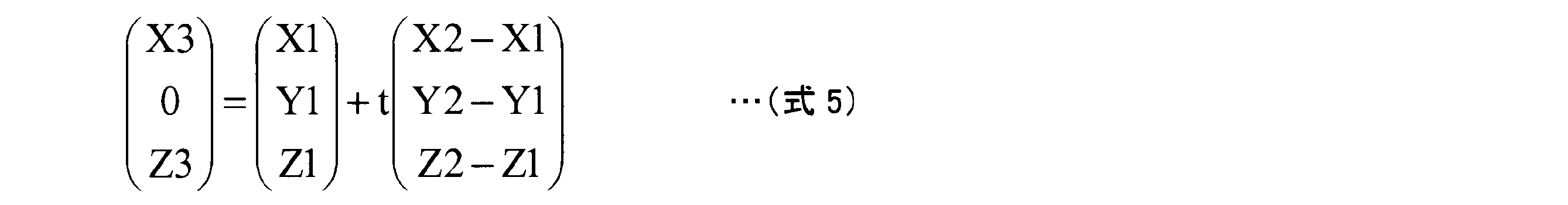
すなわち、
t=-Y1/(Y2-Y1)
X3=X1+t(X2-X1)
Z3=Z1+t(Z2-Z1)
となる。この場合、図13に示すように、仮想投影面Sp上の座標Pに投影される画像は、座標Aに対応する画像となる。このとき、図9で説明した場合と同様に、仮想基準線RL上に存在する物体Tが仮想投影面Sp上の座標Pに投影されるための補正率αは、第一の仮想直線Q1(車両中心線OL1)から仮想基準線RLまでの距離Wと、座標Aの座標X3との関係で求めることができる。
α=W/X3
このようにして求めた補正率αを用いて撮像部15cが撮像した前方画像の投影位置を補正すると図11と同様な三次元合成画像を得ることができる。なお、図12、図13に示す例の場合、仮想投影面Spにおいて、撮像部15cの設置高さ(地上高)より低い位置であれば、直線CPと地面Grとの交点を得ることができる。つまり、仮想投影面Sp上の各高さにおける補正率αをそれぞれ算出可能であり、地面Grからの高さに応じた補正が可能になり、より違和感が軽減された三次元画像の表示ができる。また、仮想投影面Spにおいて、撮像部15cの設置高さ以上の補正率αは、所定の値、例えば、算出可能な最大補正率αmaxを用いることができる。
このように、仮想投影面Spが自車前方の直立面であり、撮像部15c(前方撮像部)で撮像した前方画像のみを用いて三次元合成画像を表示装置8に表示する場合、自車前方の状況(他車や道路等)が不自然に小さく表示されたり、道幅が急激に狭くなったりするような表示が軽減される。その結果、表示装置8に表示される三次元合成画像により、自車の前方を中心とする周囲の状況の把握をより適切に違和感なく運転者に認識させやすくなる。なお、撮像部15a(後方撮像部)で撮像した後方画像を用いて後方の状況を示す三次元合成画像も同様に生成可能であり、同様に自車の後方を中心とする周囲の状況の把握をより適切に違和感なく運転者に認識させやすくなる。
なお、イグニッションスイッチがONされる度に、補正部30が撮像部15cに対する補正率αを算出し、例えばRAM14cに記憶して、三次元合成画像の生成の度に各画像の投影位置を補正するようにすることができる。
<実施形態2>
図14は、実施形態2の前方画像の投影位置および補正率の算出を説明する模式的かつ例示的な説明図である。実施形態2の場合、車両1(自車)の前方に設定される仮想投影面Spの形状が、例えば、車両1の車両中心1aを中心とする曲面である。それ以外の構成は、実施形態1の図9で示す構成と同じであり、同じ構成には同じ符号を付しその詳細な説明は省略する。ただし、図14の場合、仮想投影面Spまでの距離L1および仮想参照面Rpまでの距離L2は、車両1の車両中心1aを通り車幅方向に延びる中心線OL2を基準に定義している。
図14は、実施形態2の前方画像の投影位置および補正率の算出を説明する模式的かつ例示的な説明図である。実施形態2の場合、車両1(自車)の前方に設定される仮想投影面Spの形状が、例えば、車両1の車両中心1aを中心とする曲面である。それ以外の構成は、実施形態1の図9で示す構成と同じであり、同じ構成には同じ符号を付しその詳細な説明は省略する。ただし、図14の場合、仮想投影面Spまでの距離L1および仮想参照面Rpまでの距離L2は、車両1の車両中心1aを通り車幅方向に延びる中心線OL2を基準に定義している。
図14の場合も、仮想基準線RL(車両1の側面である端部2fに沿い、第一の方向Aに延び、第一の仮想直線Q1(撮像中心線)から車幅方向に距離Wだけ離間した位置の直線)が定義されている。この場合も、第一の仮想直線Q1は、前方撮像部(撮像部15c)から車両1の接地面(地面Gr)と平行に第一の方向Aに延びるように設定されてもよい。また、仮想基準線RLは、車幅方向において、左右いずれかの撮像部(撮像部15bまたは撮像部15d)と重なる位置かつ前方撮像部(撮像部15c)が設けられている高さから、車両1の接地面(地面Gr)と平行に第一の方向Aに延びるように設定されてもよい。そして、仮想投影面Spが曲面の場合も、補正部30による補正を施さない場合、撮像部15cが撮像する仮想参照面Rpと仮想基準線RLとの交点に存在する物体Tの第三の座標点S3に対応する画像は、車両1の前方の端部2cの中央部に固定された撮像部15cから物体Tに向かう第二の仮想直線Q2(延長線)と仮想投影面Spとが交わる第四の座標点S4に投影されてしまう。したがって、図9で説明した場合と同様に、車両1(車両形状モデルM)の前方に存在するように表示された車両Ca(物体T)は、第一の仮想直線Q1(撮像中心線)に向かって圧縮され、小さく見えるように表示される。同様に、第一の方向Aに延びる道幅が変化しない道路が投影される場合は、道幅が急激に狭くなるように表示され、運転者に違和感を与えてしまう場合がある。そこで、実施形態2における曲面の仮想投影面Spを用いる場合も、補正部30は、前方画像用の補正率αfを算出し、この補正率αfに基づき、三次元形状モデルが規定している仮想投影面Sp上の補正座標(αfX,Y,Z)に対応する前方画像の二次元座標(U,V)の画像を取得する。そして、仮想投影面Sp上の座標(X,Y,Z)に投影する。例えば、仮想投影面Sp上で第二の方向Bに存在する第四の座標点S4と第二の座標点S2との距離ΔX(第一の距離)と、第一の仮想直線Q1(車両中心線OL1)から仮想基準線RLまでの距離W(第二の距離)との比が投影位置を第二の方向B(第一の座標点S1から第二の座標点S2に向かう方向)に補正する際の補正率αfとなる。
図14から
αf=ΔX/W ・・・式1f
ΔX/(L2-L1)=W/L2 ・・・式2f
が得られる。つまり、式1fと式2fより式3fが求まる。
αf=(L2-L1)/L2 ・・・式3f
図14から
αf=ΔX/W ・・・式1f
ΔX/(L2-L1)=W/L2 ・・・式2f
が得られる。つまり、式1fと式2fより式3fが求まる。
αf=(L2-L1)/L2 ・・・式3f
このように、撮像部15cの位置を基準として仮想投影面Spまでの距離L1と仮想参照面Rpまでの距離L2から補正率αfを容易に定義することができる。補正率αfを用いて補正された三次元合成画像において、自車(車両形状モデルM)の前方に存在するように表示された車両Ca(物体T)は、図11と同様に、第一の仮想直線Q1(撮像中心線)を基準に左右に引き延ばされ、自車(車両形状モデルM)と比較して違和感が軽減された大きさに表示される。また、前方に延びる道幅の変化が緩やかになり運転者に違和感を与えにくくすることができる。上述のように、実施形態2においても、第一の仮想直線Q1と仮想基準線RLとの高さを一致させるような設定が可能で、第一の座標点S1~第四の座標点S4において、高さ方向の座標を等しくすることができる。そのため、第一の距離および第二の距離を用いた補正率αfの演算時(式1f~式3f)に高さ方向の座標の影響を受けず、安定した補正率αfの取得、および補正率αfを用いた安定した補正を実現することができる。
図15は、撮像部15b(右側方撮像部:処理対象撮像部)で撮像した右側方画像(表示対象画像)を用いて右側方の状況を示す三次元合成画像を生成する場合の補正率αsの算出を説明する模式的かつ例示的な説明図である。この場合、撮像部15c(前方撮像部)に代えて撮像部15b(右側方撮像部)を用いる点以外は図14の構成と同じあり、同じ構成には同じ符号を付しその詳細な説明は省略する。なお、撮像部15b(右側方撮像部)は、車両1の端部2fにおいて鉛直下方に向けて設置される場合がある。この場合、撮像部15bの撮像中心線は、鉛直下方を向いているため、本実施形態2のように側方の画像を表示対象画像とする場合、広角レンズや魚眼レンズで撮像された撮像画像の周縁領域が主に利用される。撮像部15b(右側方撮像部)を用いる場合、撮像部15bから車両1の車幅方向を第一の方向Aとする。そして、この第一の方向Aに撮像部15bから延びる直線を第一の仮想直線Q1とする。この場合、第一の仮想直線Q1は、一例として、撮像部15bから車両1の接地面(地面Gr)と平行に第一の方向Aに延びるように設定してもよい。そして、第一の仮想直線Q1と仮想投影面Spとが交わる位置を第一の座標点S1とする。また、撮像部15bを用いる場合、仮想基準線RLは、車長方向において、前方撮像部(撮像部15a)と重なる位置(車両1の前方の端部2c(車体の前面)を通る垂直面上)で、かつ右側方撮像部(撮像部15b)が設けられている高さと同等の高さに設定され、車両1の接地面(地面Gr)と平行に第一の方向Aに延びるように設定されてもよい。なお、図15は、車両1の車両中心1aを通り車両1の車長方向に延びる車両中心線OL1および車幅方向に延びる中心線OL2を基準に演算時に参照する距離を定義している。例えば、撮像部15b(右側方撮像部)の位置は、中心線OL2からの距離Asで定義している。また、第二の座標点S2を車両中心線OL1からの距離Bsで定義し、第三の座標点S3を車両中心線OL1からの距離Csで定義している。また、仮想参照面Rpの位置は、中心線OL2からの距離Dsで定義している。
撮像部15b(右側方撮像部)で撮像した右側方撮像を用いて三次元合成画像を生成する場合も補正部30による補正を施さない場合、仮想参照面Rp上に存在する物体T上の第三の座標点S3に対応する画像は、車両1のドアミラー2gに固定された撮像部15bから物体Tに向かう第二の仮想直線Q2(延長線)と仮想投影面Sp(Sps)とが交わる第四の座標点S4に投影されてしまう。したがって、図9、図14で説明した場合と同様に、車両1(車両形状モデルM)の右側方に存在するように表示された車両Ca(物体T)は、第一の仮想直線Q1に向かって圧縮され、小さく見えるように表示される。同様に、第一の方向A(自車の側方)の道幅が変化しない道路が投影される場合は、道幅が急激に狭くなるように表示され、運転者に違和感を与えてしまう場合がある。例えば、車両1(自車)の右横で車両1の端部2cより前方に存在する歩行者が、三次元合成画像上では、端部2cより後方に存在するような不自然な表示になる。
そこで、補正部30は、右側方画像用の補正率αsを算出し、この補正率αsに基づき、三次元形状モデルが規定している仮想投影面Sp上の補正座標(αsX,Y,Z)に対応する右側方画像の二次元座標(U,V)の画像を取得する。そして、仮想投影面Sp上の座標(X,Y,Z)に投影する。例えば、仮想投影面Sp上で第二の方向B(第一の座標点S1から第二の座標点S2に向かう方向)に存在する第四の座標点S4と第二の座標点S2との距離ΔZ(第一の距離)と、第一の仮想直線Q1から仮想基準線RLまでの第二の距離である距離(Ds-As)との比が投影位置を第二の方向Bに補正する際の補正率αsとすることができる。
図15から
αs=ΔZ/(Ds-As) ・・・式1s
ΔZ/(Cs-Bs)=(Ds-As)/C ・・・式2s
が得られる。つまり、式1sと式2sより式3sが求まる。
αs=(Cs-Bs)/Cs ・・・式3s
なお、図15より
B=√(L12-Ds2)
C=√(L22-Ds2)
である。
図15から
αs=ΔZ/(Ds-As) ・・・式1s
ΔZ/(Cs-Bs)=(Ds-As)/C ・・・式2s
が得られる。つまり、式1sと式2sより式3sが求まる。
αs=(Cs-Bs)/Cs ・・・式3s
なお、図15より
B=√(L12-Ds2)
C=√(L22-Ds2)
である。
このように、中心線OL2を基準として仮想投影面Spまでの距離L1と仮想参照面Rpまでの距離L2から補正率αsを容易に定義することができる。補正率αsを用いて補正された三次元合成画像において、自車(車両形状モデルM)の右側方に存在するように表示される車両(物体T)は、第一の仮想直線Q1を基準に前後に引き延ばされ、自車(車両形状モデルM)と比較して違和感が軽減された大きさに表示される。また、車両1の右側方に延びる道路の道幅の変化が緩やかになり運転者に違和感を与えにくくすることができる。また、歩行者等が存在する場合は、実際に近い位置に表示される。なお、撮像部15d(左側方撮像部)で撮像した左側方画像を用いて三次元合成画像を生成する場合も同様な補正が可能で、同様の効果を得ることができる。この場合においても、第一の仮想直線Q1と仮想基準線RLとの高さを一致させるような設定が可能で、第一の座標点S1~第四の座標点S4において、高さ方向の座標が等しくすることができる。そのため、第一の距離および第二の距離を用いた補正率αsの演算時(式1s~式3s)に高さ方向の座標の影響を受けず、安定した補正率αsの取得、および補正率αsを用いた安定した補正を実現することができる。
なお、撮像部15bを基準とする第一の仮想直線Q1より後方の領域に関しては、仮想基準線RLを車両1の後方の端部2e(車体の後面)で第一の方向Aに沿って設定すれば、同様に違和感を軽減する補正を行うことができる。撮像部15b(撮像部15d)の設置向きが鉛直方向ではなく、撮像部15cと同様に側方を向いている場合、第一の仮想直線Q1として、右側方(左側方)を向く撮像部15b(撮像部15d)の撮像中心線を用いて第一の座標点S1を定義することができる。
ところで、画像合成部32は、前述したように各撮像部15が撮像した画像を繋ぎ合わせてより広い領域を示す三次元合成画像を生成することができる。例えば、前方画像の左右に右側方画像と左側方画像とを繋いだ画像を合成できる。この場合も補正部30による補正を行わない場合、不自然な画像が表示される場合がある。例えば、図16に示すように、車両1の前方の端部2cに配置された撮像部15cと、車両1の左側のドアミラー2gに配置された撮像部15dとで車両1の周囲の状況を撮像する場合を考える。なお、図16は、他の画像の投影例として、図7に示すような、底面Spgと側面Spsとで構成される仮想投影面Spを用いて三次元合成画像を投影する例を示す。
図16は、仮想投影面Sp(側面Sps)のさらに遠方の位置に物体Tが存在する場合で、撮像部15cで撮像した前方画像と撮像部15dで撮像した左側方画像とを合成する場合である。物体Tは、車両1の左側の端部2dに沿って延びる仮想基準線RL上に存在するものとする。この場合、撮像部15dは、仮想基準線RLに近い位置に設置されているため、撮像部15dが撮像した画像に映る物体Tの第三の座標点S3に対応する二次元座標(U,V)を仮想投影面Sp(側面Sps)上に投影すると、物体Tの存在する位置(真の位置)に概ね対応する(投影時のずれの少ない)座標に投影される。例えば、第二の座標点S2に投影される。
一方、撮像部15cで撮像した画像に映る物体Tの第三の座標点S3に対応する二次元座標(U,V)を仮想投影面Sp(側面Sps)上に投影する場合で、補正部30による補正を行わない場合、第四の座標点S4に投影される。つまり、同じ物体Tが仮想投影面Sp上の異なる点(第二の座標点S2と第四の座標点S4)に投影される、いわゆる「二重映り」を生じる。図17は、補正部30による補正を施さない場合に表示装置8に表示される三次元合成画像の一例である。この場合、三次元合成画像のうち、特に、撮像部15c(前方撮像部)と撮像部15d(左側方撮像部)との接合領域DVLで同一の車両Ca1(物体T)が二重に映っている。同様に、撮像部15c(前方撮像部)と撮像部15b(右側方撮像部)との接合領域DVR周辺で、同一の車両Ca2(物体T)が二重に映っている。なお、補正部30による補正が実施されていないため、図10に示す例と同様に自車(車両形状モデルM)の前方に存在するように表示された車両Caは、小さく見えるように表示されている。
図18は、補正部30による補正を実行した三次元合成画像を表示装置8に表示した場合の表示例である。なお、図18に示す例において、撮像部15d(左側方撮像部)で撮像した側方の表示対象画像における物体Tは、仮想投影面Sp上に投影された場合、概ね真の位置に投影されるので補正部30による補正を行わないものとする。図18の例では、補正部30は、撮像部15c(前方撮像部)で撮像した表示対象画像に関してX方向のみの補正を行っている。
補正部30による補正を実行した結果、撮像部15c(前方撮像部)で撮像した表示対象画像に映る物体Tの第三の座標点S3に対応する二次元座標(U,V)は、第一の座標点S1から第二の座標点S2に向かう方向に補正される。その結果、撮像部15c(前方撮像部)で撮像した画像(物体T)は、撮像部15d(左側方撮像部)で撮像した側方の表示対象画像に映る物体Tの第三の座標点S3に対応する二次元座標(U,V)が投影されている位置(第二の座標点S2)に近づくように補正される。つまり、投影位置が接近し、二重映りが軽減(目立ちにくく)される。その結果、接合領域DVLの車両Ca1および接合領域DVRの車両Ca2がより鮮明に表示される(図18の場合、一例として二重映りが解消された状態が図示されている)。なお、撮像部15c(前方撮像部)で撮像した画像に関してX方向の補正が実施されたことにより、図11に示す例と同様に自車(車両形状モデルM)の前方に存在するように表示された車両Caは、自車(車両形状モデルM)と比較して違和感が軽減された大きさに表示される。
このように、補正部30による補正を行えば、仮想投影面Spが自車の周囲を囲む曲面形状で、撮像部15c(前方撮像部)、撮像部15d(左側方撮像部)、撮像部15b(右側方撮像部)で撮像した画像を用いて三次元合成画像を表示装置8に表示する場合、表示の不自然さを軽減することができる。すなわち、二重映りを目立ち難くするとともに、自車前方の状況(他車や道路等)が不自然に小さく表示されたり、道幅が急激に狭くなったりするような表示が軽減される。その結果、表示装置8に表示される三次元合成画像により、自車の前方を中心とする周囲の状況の把握をより適切に違和感なく運転者に認識させやすくなる。なお、撮像部15cで撮像した表示対象画像と撮像部15bで撮像した右側方の表示対象画像とを繋ぎ合わせる場合も同様であり同様の効果を得ることができる。また、撮像部15a撮像した表示対象画像と撮像部15b(撮像部15d)で撮像した側方の表示対象画像とを繋ぎ合わせる場合も同様であり、同様の効果を得ることができる。この場合も、実施形態1で説明したように、第一の仮想直線Q1と仮想基準線RLとの高さを一致させるような設定が可能で、第一の座標点S1~第四の座標点S4において、高さ方向の座標を等しくすることができる。そのため、第一の距離および第二の距離を用いた補正率αの演算時(式1~式3)に高さ方向の座標の影響を受けず、安定した補正率αの取得、および補正率αを用いた安定した補正を実現することができる。
<実施形態3>
図16に示す例のように、仮想投影面Spが底面Spgと側面Spsで構成される場合、上述したように、補正部30により仮想投影面Sp(側面Sps)に対する補正を施す場合、底面Spgと側面Spsとの境界線部分で画像ずれが生じる場合がある。例えば左側方画像に関して、補正率αsを用いて車両前後方向に延ばすような補正が行われた場合、側面Sps部分での補正の影響が顕著に表れる。一例として、図19に示すように、領域Jで示す部分の底面Spgと側面Spsとの境界線ja部分で路面の白線がずれるような現象が生じる。
図16に示す例のように、仮想投影面Spが底面Spgと側面Spsで構成される場合、上述したように、補正部30により仮想投影面Sp(側面Sps)に対する補正を施す場合、底面Spgと側面Spsとの境界線部分で画像ずれが生じる場合がある。例えば左側方画像に関して、補正率αsを用いて車両前後方向に延ばすような補正が行われた場合、側面Sps部分での補正の影響が顕著に表れる。一例として、図19に示すように、領域Jで示す部分の底面Spgと側面Spsとの境界線ja部分で路面の白線がずれるような現象が生じる。
そこで、実施形態3では、図20に示すように、補正率αの値を側面Spsの高さYに応じて変化させることで、底面Spgと側面Spsとの連続性を確保する。例えば、接続部分(側面Spsの高さ=0)の部分で、補正率α(Y)=1.0(補正が反映されない状態)とし、側面Spsの上端部(高さH)で補正率が最大(αmax)になるようにしている。なお、最大補正率αmaxは、実施形態1,2等で算出した補正率αである。つまり、高さYにおける補正率α(Y)は、以下に示す式6で表すことができる。
補正率α(Y)=1.0-(1.0-αmax)Y/H ・・・式6
補正部30が、補正率α(Y)を用いて撮像部15dが撮像した左側方画像の投影位置を補正した三次元合成画像が図21である。補正部30は、補正率α(Y)に基づき、三次元形状モデルが規定している側面Sps上の補正座標(α(Y)X,Y,Z)に対応する左側方画像の二次元座標(U,V)の画像を取得する。そして、側面Sps上の座標(X,Y,Z)に投影する。その結果、図21の領域Jで示すように、側面Spsに対して、底面Spgから徐々に補正が行われ、底面Spgと側面Spsとが滑らかに繋がり画像ずれが目立たない三次元合成画像を生成することができる。その結果、表示装置8に表示される三次元合成画像により、自車の前方を中心とする周囲の状況の把握をより適切に違和感なく運転者に認識させやすくなる。なお、撮像部15c(前方撮像部)が撮像した前方画像に関しても同様であり、補正率α(Y)を用いることにより、底面Spgと側面Spsとの境界部分における画像ずれが目立たなくなり、違和感のない三次元合成画像を表示することができる。
<実施形態4>
実施形態3の場合、補正率α(Y)を用いることにより、底面Spgと側面Spsとの境界部分の画像ずれは軽減できるが、側面Spsの上端部で、最大補正率αmaxとなるため、図21に示すように、側面Spsの上部に近づくのにつれて表示される物体Tの傾きが大きくなる場合がある。図21の場合、自車(車両形状モデルM)の正面より右に表示される物体T(車両)が右に傾いて表示されている。
実施形態3の場合、補正率α(Y)を用いることにより、底面Spgと側面Spsとの境界部分の画像ずれは軽減できるが、側面Spsの上端部で、最大補正率αmaxとなるため、図21に示すように、側面Spsの上部に近づくのにつれて表示される物体Tの傾きが大きくなる場合がある。図21の場合、自車(車両形状モデルM)の正面より右に表示される物体T(車両)が右に傾いて表示されている。
そこで、実施形態4では、補正率αの値を側面Spsの高さYに応じて変化させる場合に、図22に示すように、撮像部15の高さCamHで、最大補正率αmaxとし、それ以上は側面Spsの上端部まで、最大補正率αmaxを維持(固定)するように、補正率α(Y)を決定する。この場合も、底面Spgと側面Spsとの連続性を確保するために、接続部分(側面Spsの高さ=0)の部分で、補正率α(Y)=1.0とする。つまり、撮像部15の高さCamHまでの補正率α(Y)は、以下に示す式7で表すことができる。
補正率α(Y)=1.0-(1.0-αmax)Y/CamH ・・・式7
この場合、撮像部15の高さCamH以上では、最大補正率αmaxが維持されるので、側面Spsの撮像部15の高さCamH以上の部分で、投影される物体Tは傾かない。その結果、図21においては、全体が右方向に傾いていた物体Tは、図23に示すように、途中から傾きが抑制され、物体T全体としての傾きが目立たなくなり、表示される三次元合成画像の違和感がさらに軽減される。
補正率α(Y)=1.0-(1.0-αmax)Y/CamH ・・・式7
この場合、撮像部15の高さCamH以上では、最大補正率αmaxが維持されるので、側面Spsの撮像部15の高さCamH以上の部分で、投影される物体Tは傾かない。その結果、図21においては、全体が右方向に傾いていた物体Tは、図23に示すように、途中から傾きが抑制され、物体T全体としての傾きが目立たなくなり、表示される三次元合成画像の違和感がさらに軽減される。
なお、上述した各実施形態では、撮像部15cで撮像した前方画像を主画像(中央表示画像)として、撮像部15bまたは撮像部15dで撮像した側方画像を側部に繋ぎ合わせて三次元合成画像を生成する例を示した。別の実施形態では、撮像部15bまたは撮像部15dで撮像した側方画像を主画像(中央表示画像)として、撮像部15cで撮像した前方画像や撮像部15aで撮像した後方画像を側部に繋ぎ合わせて三次元合成画像を生成してもよく、同様の効果を得ることができる。
上述した各実施形態では、イグニッションスイッチがONされる度に、補正部30が各撮像部15に対する補正率を算出して、RAM14c等に記憶しておく例を説明したが、各撮像部15の位置は、車両の製造工場やディーラ等で固定され、それ以降は撮像部15の修理や交換等以外は一般的には変更されない。したがって、製造工場やディーラ等で予め各撮像部15に対する補正率αを算出し、画像の投影位置を補正するときに用いる点Sの三次元座標(αX,Y,Z)を算出し、対応する二次元座標(U,V)をROM14bやSSD14fに保存しておいてもよい。この場合、ECU14の処理負担が軽減され、比較的性能の低いECU14の利用も可能になり、ECU14を選定する際の選択範囲が広がったり、低コストのECU14の利用が可能になったりする利点がある。
本発明のいくつかの実施形態を説明したが、これらの実施形態は、例として提示したものであり、発明の範囲を限定することは意図していない。これら新規な実施形態は、その他の様々な形態で実施されることが可能であり、発明の要旨を逸脱しない範囲で、種々の省略、置き換え、変更を行うことができる。これら実施形態やその変形は、発明の範囲や要旨に含まれるとともに、請求の範囲に記載された発明とその均等の範囲に含まれる。
1…車両、8…表示装置、14…ECU、14a…CPU、15,15a,15b,15c,15d…撮像部、26…画像取得部、28…投影面取得部、30…補正部、32…画像合成部、34…三次元処理部、36…周辺画像生成部、100…表示制御システム。
Claims (9)
- 車両に設けられて前記車両の前方を含む領域を撮像する前方撮像部から得られる前方画像および前記車両の後方を含む領域を撮像する後方撮像部から得られる後方画像の少なくとも一方である、表示対象画像を取得する画像取得部と、
前記表示対象画像を投影可能で、前記車両の接地面から高さ方向に立ち上がる側面を少なくとも備える三次元の仮想投影面を取得する投影面取得部と、
前記画像取得部が取得した前記表示対象画像を前記仮想投影面に投影する場合に、前記表示対象画像を撮像した前記前方撮像部または前記後方撮像部から前記車両の車長方向である第一の方向に延びる第一の仮想直線と前記仮想投影面とが交わる位置に対応する第一の座標から、前記第一の仮想直線から前記車両の車幅方向に離間して前記第一の方向に延びる仮想基準線と前記仮想投影面とが交わる位置に対応する第二の座標に向かう第二の方向に前記表示対象画像の投影位置を補正する補正部と、
補正された前記投影位置に前記表示対象画像を投影して三次元画像を生成する画像合成部と、
を備える表示制御装置。 - 前記補正部は、前記表示対象画像を撮像した処理対象撮像部から前記第一の方向の所定の距離に設定された仮想参照面と前記仮想基準線とが交わる第三の座標と前記処理対象撮像部とを結ぶ第二の仮想直線が前記仮想投影面と交わる第四の座標と前記第二の座標との前記第二の方向における第一の距離と、前記第一の仮想直線と前記仮想基準線との前記第二の方向における第二の距離と、に基づき前記投影位置を前記第二の方向に補正する補正率を取得する請求項1に記載の表示制御装置。
- 前記仮想基準線は、前記車両の車体の左側面または右側面に沿うように前記第一の方向に延びる請求項2に記載の表示制御装置。
- 前記画像取得部は、前記車両の左側方を含む領域を撮像する左側方撮像部から得られる左側方画像および前記車両の右側方を含む領域を撮像する右側方撮像部から得られる右側方画像の少なくとも一方である側方の表示対象画像をさらに取得し、
前記仮想基準線は、前記車幅方向における前記左側方撮像部または前記右側方撮像部と重なる位置からから前記第一の方向に延び、
前記画像合成部は,前記補正部で補正された前記表示対象画像と前記側方の表示対象画像とを繋ぎ合わせて前記三次元画像を生成する、請求項2に記載の表示制御装置。 - 車両に設けられて前記車両の左側方を含む領域を撮像する左側方撮像部から得られる左側方画像および前記車両の右側方を含む領域を撮像する右側方撮像部から得られる右側方画像の少なくとも一方である、表示対象画像を取得する画像取得部と、
前記表示対象画像を投影可能で、前記車両の接地面から高さ方向に立ち上がる側面を少なくとも備える三次元の仮想投影面を取得する投影面取得部と、
前記画像取得部が取得した前記表示対象画像を前記仮想投影面に投影する場合に、前記表示対象画像を撮像した前記左側方撮像部または前記右側方撮像部から前記車両の車幅方向である第一の方向に延びる第一の仮想直線と前記仮想投影面とが交わる位置に対応する第一の座標から、前記第一の仮想直線から前記車両の車長方向に離間して前記第一の方向に延びる仮想基準線と前記仮想投影面とが交わる位置に対応する第二の座標に向かう第二の方向に前記表示対象画像の投影位置を補正する補正部と、
補正された前記投影位置に前記表示対象画像を投影して三次元画像を生成する画像合成部と、
を備える表示制御装置。 - 前記補正部は、前記表示対象画像を撮像した処理対象撮像部から前記第一の方向の所定の距離に設定された仮想参照面と前記仮想基準線とが交わる第三の座標と前記処理対象撮像部とを結ぶ第二の仮想直線が前記仮想投影面と交わる第四の座標と前記第二の座標との前記第二の方向における第一の距離と、前記第一の仮想直線と前記仮想基準線との前記第二の方向における第二の距離と、に基づき前記投影位置を前記第二の方向に補正する補正率を取得する請求項5に記載の表示制御装置。
- 前記仮想基準線は、前記車両の車体の前面または後面に沿うように前記第一の方向に延びる請求項6に記載の表示制御装置。
- 前記画像取得部は、前記車両の前方を含む領域を撮像する前方撮像部から得られる前方画像および前記車両の後方を含む領域を撮像する後方撮像部から得られる後方画像の少なくとも一方である前後方向の表示対象画像をさらに取得し、
前記仮想基準線は、前記車長方向における前記前方撮像部または前記後方撮像部と重なる位置から前記第一の方向に延び、
前記画像合成部は、前記補正部で補正された前記表示対象画像と前記前後方向の表示対象画像とを繋ぎ合わせて前記三次元画像を生成する、請求項6に記載の表示制御装置。 - 前記補正部は、前記投影位置の補正を前記車両の前記接地面からの高さに応じて変化させる請求項1から請求項8のいずれか1項に記載の表示制御装置。
Priority Applications (3)
| Application Number | Priority Date | Filing Date | Title |
|---|---|---|---|
| EP18858237.3A EP3687165B1 (en) | 2017-09-20 | 2018-02-27 | Display control device |
| US16/635,370 US10848724B2 (en) | 2017-09-20 | 2018-02-27 | Display control device |
| CN201880059730.5A CN111095921B (zh) | 2017-09-20 | 2018-02-27 | 显示控制装置 |
Applications Claiming Priority (2)
| Application Number | Priority Date | Filing Date | Title |
|---|---|---|---|
| JP2017180532A JP6958163B2 (ja) | 2017-09-20 | 2017-09-20 | 表示制御装置 |
| JP2017-180532 | 2017-09-20 |
Publications (1)
| Publication Number | Publication Date |
|---|---|
| WO2019058585A1 true WO2019058585A1 (ja) | 2019-03-28 |
Family
ID=65809622
Family Applications (1)
| Application Number | Title | Priority Date | Filing Date |
|---|---|---|---|
| PCT/JP2018/007263 WO2019058585A1 (ja) | 2017-09-20 | 2018-02-27 | 表示制御装置 |
Country Status (5)
| Country | Link |
|---|---|
| US (1) | US10848724B2 (ja) |
| EP (1) | EP3687165B1 (ja) |
| JP (1) | JP6958163B2 (ja) |
| CN (1) | CN111095921B (ja) |
| WO (1) | WO2019058585A1 (ja) |
Cited By (2)
| Publication number | Priority date | Publication date | Assignee | Title |
|---|---|---|---|---|
| CN110991453A (zh) * | 2019-12-23 | 2020-04-10 | 浙江凯拓机电有限公司 | 平面图像斜视梯形矫正方法及矫正系统 |
| CN113993747A (zh) * | 2019-09-13 | 2022-01-28 | 马瑞利株式会社 | 显示装置及显示方法 |
Families Citing this family (4)
| Publication number | Priority date | Publication date | Assignee | Title |
|---|---|---|---|---|
| EP3567427B1 (en) * | 2018-03-12 | 2023-12-13 | Guangdong Oppo Mobile Telecommunications Corp., Ltd. | Control method and control device for a depth camera |
| US10380440B1 (en) * | 2018-10-23 | 2019-08-13 | Capital One Services, Llc | Method for determining correct scanning distance using augmented reality and machine learning models |
| DE102019206196A1 (de) * | 2019-04-30 | 2020-11-05 | Volkswagen Aktiengesellschaft | Fahrzeug mit einer Benutzerschnittstelle |
| CN113119877A (zh) * | 2021-04-16 | 2021-07-16 | 恒大恒驰新能源汽车研究院(上海)有限公司 | 车载屏幕控制系统及车载屏幕控制方法 |
Citations (7)
| Publication number | Priority date | Publication date | Assignee | Title |
|---|---|---|---|---|
| JP2004021307A (ja) * | 2002-06-12 | 2004-01-22 | Matsushita Electric Ind Co Ltd | 運転支援装置 |
| JP2009232310A (ja) * | 2008-03-25 | 2009-10-08 | Fujitsu Ltd | 車両用画像処理装置、車両用画像処理方法、車両用画像処理プログラム |
| WO2013175753A1 (ja) | 2012-05-22 | 2013-11-28 | 三菱電機株式会社 | 画像処理装置 |
| JP2014165633A (ja) * | 2013-02-25 | 2014-09-08 | Suzuki Motor Corp | 画像表示装置 |
| WO2015194501A1 (ja) * | 2014-06-20 | 2015-12-23 | クラリオン株式会社 | 映像合成システムとそのための映像合成装置及び映像合成方法 |
| JP2016046747A (ja) * | 2014-08-26 | 2016-04-04 | 富士通テン株式会社 | 画像処理装置、画像処理方法、及び、画像表示システム |
| JP2017068826A (ja) * | 2015-09-30 | 2017-04-06 | アイシン精機株式会社 | 車両用画像処理装置 |
Family Cites Families (23)
| Publication number | Priority date | Publication date | Assignee | Title |
|---|---|---|---|---|
| US6717610B1 (en) * | 1998-11-25 | 2004-04-06 | Donnelly Corporation | Wide angle image capture system for vehicle |
| JP4642723B2 (ja) * | 2006-09-26 | 2011-03-02 | クラリオン株式会社 | 画像生成装置および画像生成方法 |
| JP2008102620A (ja) | 2006-10-17 | 2008-05-01 | Toyota Motor Corp | 画像処理装置 |
| JP2008271308A (ja) * | 2007-04-23 | 2008-11-06 | Sanyo Electric Co Ltd | 画像処理装置及び方法並びに車両 |
| JP5439890B2 (ja) * | 2009-03-25 | 2014-03-12 | 富士通株式会社 | 画像処理方法、画像処理装置及びプログラム |
| WO2010119496A1 (ja) * | 2009-04-13 | 2010-10-21 | 富士通株式会社 | 画像処理装置、画像処理プログラム、画像処理方法 |
| KR100956858B1 (ko) * | 2009-05-19 | 2010-05-11 | 주식회사 이미지넥스트 | 차량 주변 영상을 이용하는 차선 이탈 감지 방법 및 장치 |
| EP2608149B1 (en) * | 2010-08-19 | 2021-04-21 | Nissan Motor Co., Ltd. | Three-dimensional object detection device and three-dimensional object detection method |
| WO2012120561A1 (ja) * | 2011-03-08 | 2012-09-13 | 三菱電機株式会社 | 移動体周辺映像補正装置 |
| JP5870608B2 (ja) * | 2011-10-13 | 2016-03-01 | アイシン精機株式会社 | 画像生成装置 |
| DE102011084554A1 (de) * | 2011-10-14 | 2013-04-18 | Robert Bosch Gmbh | Verfahren zur Darstellung eines Fahrzeugumfeldes |
| US9762880B2 (en) * | 2011-12-09 | 2017-09-12 | Magna Electronics Inc. | Vehicle vision system with customized display |
| JP5938222B2 (ja) * | 2012-02-07 | 2016-06-22 | 日立建機株式会社 | 運搬車両の周囲監視装置 |
| US10089537B2 (en) * | 2012-05-18 | 2018-10-02 | Magna Electronics Inc. | Vehicle vision system with front and rear camera integration |
| US9225942B2 (en) * | 2012-10-11 | 2015-12-29 | GM Global Technology Operations LLC | Imaging surface modeling for camera modeling and virtual view synthesis |
| WO2014100985A1 (en) * | 2012-12-26 | 2014-07-03 | Harman International Industries, Incorporated | Method and system for generating a surround view |
| CN105556956B (zh) * | 2013-09-19 | 2019-01-22 | 富士通天株式会社 | 图像生成装置、图像显示系统、图像生成方法以及图像显示方法 |
| US9509909B2 (en) * | 2013-11-18 | 2016-11-29 | Texas Instruments Incorporated | Method and apparatus for a surround view camera system photometric alignment |
| JP2016225865A (ja) | 2015-06-01 | 2016-12-28 | 東芝アルパイン・オートモティブテクノロジー株式会社 | 俯瞰画像生成装置 |
| US10523865B2 (en) * | 2016-01-06 | 2019-12-31 | Texas Instruments Incorporated | Three dimensional rendering for surround view using predetermined viewpoint lookup tables |
| CN106994936A (zh) * | 2016-01-22 | 2017-08-01 | 广州求远电子科技有限公司 | 一种3d全景泊车辅助系统 |
| CN107133912A (zh) * | 2017-04-01 | 2017-09-05 | 纵目科技(上海)股份有限公司 | 全景泊车图像畸变校正方法及装置 |
| JP6897442B2 (ja) * | 2017-09-12 | 2021-06-30 | 株式会社Jvcケンウッド | 車両用装置、キャリブレーション結果判定システム、および、キャリブレーション結果判定方法、ならびに、プログラム |
-
2017
- 2017-09-20 JP JP2017180532A patent/JP6958163B2/ja active Active
-
2018
- 2018-02-27 CN CN201880059730.5A patent/CN111095921B/zh active Active
- 2018-02-27 WO PCT/JP2018/007263 patent/WO2019058585A1/ja unknown
- 2018-02-27 US US16/635,370 patent/US10848724B2/en active Active
- 2018-02-27 EP EP18858237.3A patent/EP3687165B1/en active Active
Patent Citations (7)
| Publication number | Priority date | Publication date | Assignee | Title |
|---|---|---|---|---|
| JP2004021307A (ja) * | 2002-06-12 | 2004-01-22 | Matsushita Electric Ind Co Ltd | 運転支援装置 |
| JP2009232310A (ja) * | 2008-03-25 | 2009-10-08 | Fujitsu Ltd | 車両用画像処理装置、車両用画像処理方法、車両用画像処理プログラム |
| WO2013175753A1 (ja) | 2012-05-22 | 2013-11-28 | 三菱電機株式会社 | 画像処理装置 |
| JP2014165633A (ja) * | 2013-02-25 | 2014-09-08 | Suzuki Motor Corp | 画像表示装置 |
| WO2015194501A1 (ja) * | 2014-06-20 | 2015-12-23 | クラリオン株式会社 | 映像合成システムとそのための映像合成装置及び映像合成方法 |
| JP2016046747A (ja) * | 2014-08-26 | 2016-04-04 | 富士通テン株式会社 | 画像処理装置、画像処理方法、及び、画像表示システム |
| JP2017068826A (ja) * | 2015-09-30 | 2017-04-06 | アイシン精機株式会社 | 車両用画像処理装置 |
Non-Patent Citations (1)
| Title |
|---|
| See also references of EP3687165A4 |
Cited By (4)
| Publication number | Priority date | Publication date | Assignee | Title |
|---|---|---|---|---|
| CN113993747A (zh) * | 2019-09-13 | 2022-01-28 | 马瑞利株式会社 | 显示装置及显示方法 |
| CN113993747B (zh) * | 2019-09-13 | 2023-06-06 | 马瑞利株式会社 | 显示装置及显示方法 |
| CN110991453A (zh) * | 2019-12-23 | 2020-04-10 | 浙江凯拓机电有限公司 | 平面图像斜视梯形矫正方法及矫正系统 |
| CN110991453B (zh) * | 2019-12-23 | 2022-05-31 | 浙江凯拓机电有限公司 | 平面图像斜视梯形矫正方法及矫正系统 |
Also Published As
| Publication number | Publication date |
|---|---|
| US20200186767A1 (en) | 2020-06-11 |
| JP2019057800A (ja) | 2019-04-11 |
| EP3687165B1 (en) | 2022-05-25 |
| CN111095921B (zh) | 2021-06-08 |
| JP6958163B2 (ja) | 2021-11-02 |
| EP3687165A1 (en) | 2020-07-29 |
| EP3687165A4 (en) | 2020-07-29 |
| US10848724B2 (en) | 2020-11-24 |
| CN111095921A (zh) | 2020-05-01 |
Similar Documents
| Publication | Publication Date | Title |
|---|---|---|
| JP6958163B2 (ja) | 表示制御装置 | |
| JP7039879B2 (ja) | 表示制御装置 | |
| JP7222254B2 (ja) | 周辺表示制御装置 | |
| JP6115104B2 (ja) | 車両の制御装置、及び制御方法 | |
| WO2014132680A1 (ja) | 車両の制御装置、及びプログラム | |
| US9994157B2 (en) | Periphery monitoring apparatus and periphery monitoring system | |
| CN111066319B (zh) | 图像处理装置 | |
| WO2018070298A1 (ja) | 表示制御装置 | |
| JP6876236B2 (ja) | 表示制御装置 | |
| CN110997409B (zh) | 周边监控装置 | |
| JP7013751B2 (ja) | 画像処理装置 | |
| JP7119798B2 (ja) | 表示制御装置 | |
| JP7314518B2 (ja) | 周辺監視装置 | |
| JP7056034B2 (ja) | 周辺監視装置 | |
| JP6930202B2 (ja) | 表示制御装置 | |
| JP6965563B2 (ja) | 周辺監視装置 | |
| JP2022009331A (ja) | 周辺監視装置 |
Legal Events
| Date | Code | Title | Description |
|---|---|---|---|
| 121 | Ep: the epo has been informed by wipo that ep was designated in this application |
Ref document number: 18858237 Country of ref document: EP Kind code of ref document: A1 |
|
| NENP | Non-entry into the national phase |
Ref country code: DE |
|
| ENP | Entry into the national phase |
Ref document number: 2018858237 Country of ref document: EP Effective date: 20200420 |