WO2019049574A1 - 電子機器、情報処理装置およびpos端末装置 - Google Patents
電子機器、情報処理装置およびpos端末装置 Download PDFInfo
- Publication number
- WO2019049574A1 WO2019049574A1 PCT/JP2018/029223 JP2018029223W WO2019049574A1 WO 2019049574 A1 WO2019049574 A1 WO 2019049574A1 JP 2018029223 W JP2018029223 W JP 2018029223W WO 2019049574 A1 WO2019049574 A1 WO 2019049574A1
- Authority
- WO
- WIPO (PCT)
- Prior art keywords
- cover
- slide member
- switch
- main body
- electronic device
- Prior art date
- Legal status (The legal status is an assumption and is not a legal conclusion. Google has not performed a legal analysis and makes no representation as to the accuracy of the status listed.)
- Ceased
Links
Images








Classifications
-
- G—PHYSICS
- G06—COMPUTING OR CALCULATING; COUNTING
- G06Q—INFORMATION AND COMMUNICATION TECHNOLOGY [ICT] SPECIALLY ADAPTED FOR ADMINISTRATIVE, COMMERCIAL, FINANCIAL, MANAGERIAL OR SUPERVISORY PURPOSES; SYSTEMS OR METHODS SPECIALLY ADAPTED FOR ADMINISTRATIVE, COMMERCIAL, FINANCIAL, MANAGERIAL OR SUPERVISORY PURPOSES, NOT OTHERWISE PROVIDED FOR
- G06Q20/00—Payment architectures, schemes or protocols
- G06Q20/08—Payment architectures
- G06Q20/20—Point-of-sale [POS] network systems
- G06Q20/208—Input by product or record sensing, e.g. weighing or scanner processing
-
- G—PHYSICS
- G07—CHECKING-DEVICES
- G07G—REGISTERING THE RECEIPT OF CASH, VALUABLES, OR TOKENS
- G07G1/00—Cash registers
- G07G1/0018—Constructional details, e.g. of drawer, printing means, input means
-
- G—PHYSICS
- G06—COMPUTING OR CALCULATING; COUNTING
- G06K—GRAPHICAL DATA READING; PRESENTATION OF DATA; RECORD CARRIERS; HANDLING RECORD CARRIERS
- G06K7/00—Methods or arrangements for sensing record carriers, e.g. for reading patterns
- G06K7/10—Methods or arrangements for sensing record carriers, e.g. for reading patterns by electromagnetic radiation, e.g. optical sensing; by corpuscular radiation
- G06K7/14—Methods or arrangements for sensing record carriers, e.g. for reading patterns by electromagnetic radiation, e.g. optical sensing; by corpuscular radiation using light without selection of wavelength, e.g. sensing reflected white light
- G06K7/1404—Methods for optical code recognition
- G06K7/1408—Methods for optical code recognition the method being specifically adapted for the type of code
- G06K7/1413—1D bar codes
-
- G—PHYSICS
- G06—COMPUTING OR CALCULATING; COUNTING
- G06Q—INFORMATION AND COMMUNICATION TECHNOLOGY [ICT] SPECIALLY ADAPTED FOR ADMINISTRATIVE, COMMERCIAL, FINANCIAL, MANAGERIAL OR SUPERVISORY PURPOSES; SYSTEMS OR METHODS SPECIALLY ADAPTED FOR ADMINISTRATIVE, COMMERCIAL, FINANCIAL, MANAGERIAL OR SUPERVISORY PURPOSES, NOT OTHERWISE PROVIDED FOR
- G06Q20/00—Payment architectures, schemes or protocols
- G06Q20/08—Payment architectures
- G06Q20/20—Point-of-sale [POS] network systems
- G06Q20/209—Specified transaction journal output feature, e.g. printed receipt or voice output
-
- H—ELECTRICITY
- H05—ELECTRIC TECHNIQUES NOT OTHERWISE PROVIDED FOR
- H05K—PRINTED CIRCUITS; CASINGS OR CONSTRUCTIONAL DETAILS OF ELECTRIC APPARATUS; MANUFACTURE OF ASSEMBLAGES OF ELECTRICAL COMPONENTS
- H05K5/00—Casings, cabinets or drawers for electric apparatus
Definitions
- the present invention relates to an electronic device, an information processing device, and a POS terminal device.
- an electronic apparatus including an information processing apparatus such as a POS (Point Of Sales) terminal apparatus, for example, it is possible to attach or remove a cover of the apparatus without a tool in order to reduce the number of man-hours required for maintenance. There is.
- POS Point Of Sales
- Patent Document 1 discloses a POS terminal device capable of removing a rear cover attached to a frame of a housing without using a tool.
- a person who performs maintenance can easily remove the cover, including the POS terminal device disclosed in Patent Document 1, in which the cover can be attached and removed without using a tool. On the other hand, even a person who is not permitted to remove the cover can easily remove the cover.
- An object of the present invention is to provide an electronic device that can reduce the possibility of being subjected to mischief.
- Another object of the present invention is to provide an information processing apparatus capable of reducing the possibility of receiving mischief.
- Still another object of the present invention is to provide a POS terminal apparatus capable of reducing the possibility of being subjected to mischief.
- a device main body having a power switch, and a cover of the device main body covering at least a part including the power switch, the cover slidingly removing in the width direction or the depth direction
- a cover body attached to the device body, a switch window which is provided on the cover body and causes the power switch to communicate with the outside of the cover to operate the power switch, and is opened upward.
- a switch door possibly mounted on the cover body and covering the switch window, and adjacent to the switch door of the cover body slidably slidable from a lower first position to an upper second position
- a slide member attached, and the device body has a projection projecting upward, and the slide member is directed downward
- the lower end portion of the switch door contacts the upper end portion of the slide member in the first position when the switch door is closed, and the lower end portion of the switch door is opened when the switch door is opened.
- the electronic device is an information processing apparatus
- the apparatus main body further includes a control unit that performs information processing, and the control unit performs arithmetic processing of information, and at least a program.
- a storage unit for storing software; and an information input / output unit for inputting information before operation processing and outputting information after operation processing, the operation unit storing the information stored in the storage unit
- An information processing apparatus can be obtained which performs arithmetic processing based on program software.
- a POS terminal device which is a POS terminal device, and further includes a display for a store clerk and a display for a customer.
- the contact of the upper end portion of the slide member is released by opening the switch door, whereby the slide member is removed. Allowing sliding to a second position, and sliding the slide member towards the second position, the side surface of the projection of the device body of the side surface of the claw portion of the slide member And allowing the slide in the width direction or the depth direction of the cover main body by releasing the contact with the cover, and a step of sliding the cover main body in the width direction or the depth direction and removing it from the device main body; And a method of removing the cover of the electronic device.
- the electronic device, the information processing device, and the POS terminal device according to the present invention can reduce the possibility of receiving mischief.
- FIG. 1 is a perspective view of a POS terminal according to an embodiment of the present invention, where (a) is a perspective view from the front, and (b) is a perspective view from the rear. It is the perspective view which looked at the POS terminal device in the state where the display part for salesclerks, the display part for customers, and the pedestal for reader-writers were removed from the back.
- FIG. 3 is a perspective view of the POS terminal and the cover in a state where the cover is removed from the POS terminal shown in FIG. 2;
- FIG. 3 is a perspective view of the inside of the POS terminal device and the cover in a state where the cover is removed from the POS terminal device shown in FIG. 2.
- (A) is the perspective view which looked at the POS terminal apparatus of the state which removed the display part for salesclerks, the display part for customers, and the base for reader-writers from the back
- (b) is an expansion perspective view of switch vicinity.
- (A) is a perspective view when a switch door is opened from the state of the POS terminal device shown in FIG. 5,
- (b) is an enlarged perspective view of the switch door vicinity.
- (A) is a perspective view when sliding a slide member upwards from the state of the POS terminal device shown in FIG. 6,
- (b) is an expansion perspective view of the switch door vicinity.
- FIG. 6 is a top view of the POS terminal apparatus with the display unit for a store clerk, the display unit for a customer, and the pedestal for a reader / writer removed.
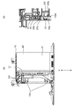
- (A) is an arrow view of the POS terminal along the cutting line 10A-10A in FIG. 9,
- (b) is an enlarged view of the vicinity of the switch door.
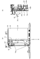
- (A) is an arrow view when the switch door is opened from the state of the POS terminal shown in FIG.
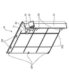
- FIG. 10 is a perspective view of the inside of the cover of the POS terminal according to the embodiment of the present invention.
- A) is a top view
- (b) is a front view
- (c) is a bottom view
- (d) is a left side view
- (e) is a right side view of the door holding portion of the POS terminal according to the embodiment of the present invention
- (F) is a rear view.
- (A) is a top view
- (b) is a front view
- (c) is a bottom view
- (d) is a left side view
- (e) is a right side view, of the switch door of the POS terminal according to the embodiment of the present invention.
- (F) is a rear view.
- (A) is a top view
- (b) is a front view
- (c) is a bottom view
- (d) is a left side view
- (e) is a right side view of the switch extension portion of the POS terminal according to the embodiment of the present invention
- (F) is a rear view.
- (A) of the switch extension shown in FIG. 16 is a front view
- (b) is a cross-sectional view taken along the section line 17B-17B in FIG.
- FIG. 16 (a).
- (A) is a top view
- (b) is a front view
- (c) is a bottom view
- (d) is a left side view
- (e) is a right side view
- FIG. (F) is a rear view.
- (A) of the slide member shown in FIG. 18 is a top view
- (b) is a bottom view. It is a perspective view inside the state which attached the slide member to the cover main body of POS terminal device by embodiment of this invention.
- (A) is an inside figure and (b) is another inside figure in the state which attached the slide member to the cover main body of POS terminal device by embodiment of this invention.
- FIG. 22 (b) is an inside view
- (b) is an enlarged view of a central portion in the vertical direction
- (c) is a view of FIG. 22 (b) in a state where the slide member is attached to the cover body of the POS terminal according to the embodiment 22D is an enlarged cross-sectional view taken along line 22D-22D in FIG. 22 (b).
- (A) And (b) is a perspective view of the state in which the receipt printer and the barcode reader were mounted in the POS terminal device by embodiment of this invention.
- the symbol W indicates the width direction
- the symbol H indicates the height direction
- the symbol D indicates the depth direction.
- a POS terminal apparatus as an electronic apparatus (information processing apparatus) according to an embodiment of the present invention has a control box 11 incorporating a control unit and a power switch 12 (shown in FIG. 3 etc.)
- the apparatus main body 10 and a cover 20 covering at least a part including the power switch 12 are provided.
- control unit built in the control box 11 inputs an arithmetic unit that performs arithmetic processing of information, a storage unit that stores at least program software, and information before arithmetic processing, while after the arithmetic processing And an information input / output unit that outputs information.
- the arithmetic unit performs arithmetic processing based on the program software stored in the storage unit.
- the information processing apparatus further includes a store clerk display 40S and a customer display 40C.
- the present POS terminal apparatus has a base unit 30.
- the base portion 30 has a cable lead-out portion 35 for leading out a cable for electrically connecting the apparatus main body 10 to another electronic device (not shown).
- the cover 20 is provided on the cover main body 21 which is removably attached to the apparatus main body 10 by sliding in the width direction W or the depth direction D (in the present example, the width direction W) and the cover main body 21.
- a switch window 24 (shown in FIG. 6 (b) etc.) for connecting the power switch 12 to the outside of the cover 20 for operation and a switch window 24 attached to the cover main body 21 openably upward.
- a slide member 23 mounted adjacent to the switch door 22 of the cover main body 21 so as to be slidable from the lower first position to the upper second position. .
- the switch door 22 shown in FIGS. 15 (a) to 15 (f) can be opened diagonally upward around the rotation axis extending in the depth direction D or the width direction W (in this example, the depth direction D)
- the cover main body 21 is attached.
- the slide member 23 shown in FIGS. 18 (a) to 18 (f) and FIGS. 19 (a) and 19 (b) is a switch of the cover main body 21 slidably from the first position below to the second position above. It is attached to the lower side of the door 22.
- the slide member 23 attached to the cover main body 21 has a shape continuous to the cover main body 21, in other words, a design common or integral with the cover main body 21 as apparent from FIG. 5A and the like. There is. Therefore, when the slide member 23 is at the first position below, it is difficult to determine that the slide member 23 is slidable.
- the apparatus main body 10 has a protrusion 10 p (shown in FIGS. 8A and 8B or the like) protruding upward.
- the slide member 23 has a claw 23 f (shown in FIG. 13 and the like) protruding downward.
- the switch door 22 is biased to be in a closed state by its own weight.
- the slide member 23 is biased to its first position by its own weight.
- the cover 20 extends between the switch window 24 and the power switch 12 and is attached to the cover main body 21 so as to be displaceable in the operating direction of the power switch 12 (see FIG. 6B, etc. Furthermore, it has it.
- the switch extensions 60 shown in FIGS. 16 (a) to 16 (f) and FIGS. 17 (a) and 17 (b) make it possible to operate the power switch 12 from the outside of the cover 20.
- the switch door 22 is The lower end 22L contacts the upper end 23U of the slide member 23 in the first position when the switch door 22 is closed, and contacts the upper end 23U of the slide member 23 when the switch door 22 is opened.
- the claws of the slide member 23 are formed.
- the side surface 23fs in the width direction W or the depth direction D (in this example, the width direction W) of 23f is the width direction W or the depth direction of the protrusion 10p of the device body 10
- the slide member 23 is in the second position, the contact with the side surface 10 ps of the protrusion 10 p of the apparatus main body 10 is released while the side surface 10 ps in the D (in this example, width direction W) contacts.
- the POS terminal further includes a receipt printer 70 as a peripheral device and a bar code reader 80 as shown in FIG.
- a POS terminal apparatus as an electronic apparatus (information processing apparatus) according to an embodiment of the present invention has a control box in which a control unit is incorporated.
- An apparatus main body 10 having a display 11, a display unit 40S for a store clerk, a display unit 40C for a customer, and a base unit 30 on which an accessory device is placed.
- the store clerk display unit 40S and the customer display unit 40C both have a display with a touch panel, and are supported so as to be adjustable in angle by a display support unit 50 provided above the apparatus main body 10.
- a display support unit 50 provided above the apparatus main body 10.
- connection cable to an attachment apparatus is derived
- a reader / writer pedestal 32 and a bar code reader placement unit 33 are provided on the base unit 30.
- FIG. 2 shows a state in which the display unit 40S for salesclerk, the display unit 40C for customer, and the pedestal 32 for reader / writer are removed from the state shown in FIG.
- the hinge 52S of the display unit 40S for a clerk and the hinge 52C of the display 40C for a customer remain attached.
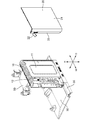
- FIG. 3 shows a state in which the cover 20 is removed from the state of FIG.
- the connection cable attached to the control box 11 in which the control part is incorporated is abbreviate
- the control box 11 has a power switch 12.
- the L-shaped engaging claws 20 f (five places) of the cover 20 respectively enter five recesses 10 s of the apparatus main body 10. Further, the two convex portions 20 p provided at the lower end of the cover 20 are inserted into the two concave portions 10 d of the apparatus main body 10.
- the switch door 22 is flipped up to be in an open state.
- the switch extension 60 is exposed in the switch window 24.
- the slide member 23 can be pushed upward.
- the cover 20 is removed from the apparatus body 10 as described above.
- FIG. 13 the structure of the cover 20 will be described with reference to FIGS. 13 to 20.
- the cover 20 is configured of a cover main body 21, a door holding portion 25, a switch door 22, a switch extension portion 60 and a slide member 23.
- the engagement claws 20 f are provided at five places, and two convex parts 20 p are provided at the lower end.
- the door holding portion 25 shown in FIGS. 14 (a) to 14 (f) is assembled to the cover main body 21.
- the door holding portion 25 is provided with two holes 25 x for inserting a pivot of the switch door 22 described later.
- the switch door 22 shown in FIGS. 15 (a) to 15 (f) is rotatably held by the door holding portion 25 assembled to the cover main body 21.
- the pivot shaft 22 x of the switch door 22 is inserted into the hole 25 x of the door holding unit 25.
- the switch door 22 can be pivotably opened about the pivot shaft 22x.
- the switch extension 60 is assembled to the cover body 21.
- the switch extension 60 is constituted by the holding portion 61, the movable portion 62 and the compression coil spring 66.
- the movable portion 62 is L-shaped so that the power switch 12 (FIG. 3, FIG. 4) of the control box 11 can be pressed from the switch window 24 (FIG. 6 (b), FIG. 11 (b)) of the cover main body 21.
- the center line of the operating surface 63 which is shown and provided with a symbol representing the power switch 12 and the center line of the power switch 12 are at different positions.
- Stoppers 65 are provided on the contact surface 64 at four locations so as not to push the power switch 12 too much.
- the slide member 23 is provided with hook-like claws 23f projecting downward in two places.
- protrusions 23 p to be inserted into corresponding holes of the cover main body 21 are provided. Two of them are at positions overlapping the claws 23f.
- protrusions 23 t to be inserted into corresponding holes of the cover main body 21 are provided.
- the slide member 23 has three projections 23 p on the slide member 23 as described above.
- a protrusion 23t is provided.
- the cover body 21 is provided with a projection 23p of the slide member 23, a hole 21d corresponding to the projection 23t, and a hole 21g.
- the protrusion 23 p and the protrusion 23 t of the slide member 23 are inserted into the hole 21 d and the hole 21 g of the cover main body 21, and the slide member 23 is assembled to the cover main body 21.
- FIGS. 20 the slide member 23 has three projections 23 p on the slide member 23 as described above.
- a protrusion 23t is provided.
- the cover body 21 is provided with a projection 23p of the slide member 23, a hole 21d corresponding to the projection 23t, and a hole 21g.
- the end portions of the holes 21d of the cover main body 21, the protrusions 23p of the slide member 23 inserted into the holes 21g, and the protrusions 23t have a hook shape. Therefore, the slide member 23 does not come off the cover main body 21.
- the slide member 23 is movable by the difference of the dimensions of the hole 21 d of the cover main body 21, the protrusion 23 p of the slide member 23 to be inserted into the hole 21 g, and the protrusion 23 t.
- the present POS terminal device has a receipt printer 70 and a bar code reader 80 as attached devices on the side of the display unit 40S for the clerk on the base portion 30. There is. A reader / writer pedestal 32 is attached to the customer display unit 40C on the base unit 30, and a reader / writer (not shown) as an accessory device is mounted as needed.
- FIGS. 23A and 23B the connection cable for connecting the accessory device and the device main body 10 is not shown.
- the switch extension 60 is assembled to the cover 20.
- the switch extension may be assembled to the control box instead of the cover.
- the switch extension may be incorporated in the control box instead of being added to the outside of the control box.
- the control box may have no switch extension and be provided at a position where the power switch itself can be pressed through the switch window.
- the electronic device according to the present invention can be easily removed without the tool, while the operation knob for removing the cover is not exposed to the outside of the electronic device. Or the operation knob itself does not exist. Further, in order to remove the cover, it is necessary to perform an operation of sliding the cover, that is, a plurality of types of operations while maintaining the state in which the slide member is further pushed up after opening the switch door. As a result, the risk of mischief by a person who is not permitted to operate the electronic device such as a customer can be reduced.
- the switch door is not only a member for concealing the power switch which does not want to receive the mischief by a person who is not permitted to operate the electronic device, but also a kind of locking member that needs an operation to remove the cover. is there. For this reason, cost reduction can be achieved compared with the case where the member for covering a power switch and the lock member of a cover are provided separately.
- the slide member like the switch door, is not only a kind of lock member that needs to be operated to remove the cover, but also plays a function as an outer cover member that covers the apparatus main body together with the cover main body. For this reason, cost reduction can be aimed at compared with the case where an outer skin member and a lock member of a cover are provided separately. In addition, even if a person who is not permitted to operate the electronic device looks at the slide member, it is considered unlikely that the person will notice that it is the lock member.
Landscapes
- Business, Economics & Management (AREA)
- Physics & Mathematics (AREA)
- Engineering & Computer Science (AREA)
- Accounting & Taxation (AREA)
- General Physics & Mathematics (AREA)
- Theoretical Computer Science (AREA)
- Finance (AREA)
- General Business, Economics & Management (AREA)
- Strategic Management (AREA)
- Health & Medical Sciences (AREA)
- Electromagnetism (AREA)
- General Health & Medical Sciences (AREA)
- Toxicology (AREA)
- Artificial Intelligence (AREA)
- Computer Vision & Pattern Recognition (AREA)
- Cash Registers Or Receiving Machines (AREA)
Abstract
電源スイッチ12を有する装置本体10と、カバー20とを有し、カバー20は、スライドして取り外し可能なカバー本体21と、スイッチ窓部24と、スイッチ扉22と、下方の第1の位置から上方の第2の位置に向かってスライド可能なスライド部材23とを有し、装置本体10は、突起部10pを有し、スライド部材23は、爪部23fを有し、スイッチ扉22の下端部22Lは、閉扉時は、スライド部材23の上端部23Uに接触する一方、開扉時は、上端部23Uへの接触を解除し、スライド部材23の爪部23fの側面23fsは、スライド部材23が第1の位置にあるときは、装置本体10の突起部10pの側面10psに接触する一方、第2の位置にあるときは、側面10psへの接触を解除する、電子機器。
Description
本発明は、電子機器、情報処理装置およびPOS端末装置に関する。
POS(Point Of Sales)端末装置等の情報処理装置をも含む電子機器においては、メインテナンスに要する工数を削減すべく、例えば、装置のカバーの取り付けや取り外しを工具なしで行うことを可能にしたものがある。
特許文献1には、筐体のフレームに取り付けられたリアカバーを、工具なしで取り外すことができるPOS端末装置が開示されている。
特許文献1に開示されたPOS端末装置をも含め、カバーの取り付けや取り外しを工具なしで行える電子機器は、メインテナンスを行う者がカバーを容易に取り外すことができる。その反面、カバーの取り外しを許されていない者であっても、カバーを容易に取り外す行うことができてしまう。
特許文献1に開示されたPOS端末装置においては、特許文献1の段落0058に記載されているように、リアカバーを取り外すための操作ツマミが一見して分かり難い位置に設けられている。このため、カバーの取り外しを許されていない者によるイタズラを、ある程度は抑制できる。しかし、上記操作ツマミがPOS端末装置の下方に露出しているのは事実である。このように操作ツマミが露出していると、イタズラを招来する可能性を否定できない。
このため、特許文献1に開示されたPOS端末装置をも含め、電子機器においては、イタズラを受ける可能性を低減できる構成が望まれる。
本発明の目的は、イタズラを受ける可能性を低減できる電子機器を提供することである。
本発明の他の目的は、イタズラを受ける可能性を低減できる情報処理装置を提供することである。
本発明のさらに他の目的は、イタズラを受ける可能性を低減できるPOS端末装置を提供することである。
本発明によれば、電源スイッチを有する装置本体と、前記装置本体の、前記電源スイッチを含む少なくとも一部を覆うカバーと、を有し、前記カバーは、幅方向または奥行方向にスライドして取り外し可能に前記装置本体に取り付けられたカバー本体と、前記カバー本体に設けられ、前記電源スイッチを操作するために該電源スイッチを前記カバーの外部と連通させるスイッチ窓部と、上方に向かって開扉可能に前記カバー本体に取り付けられ、前記スイッチ窓部を覆蓋するスイッチ扉と、下方の第1の位置から上方の第2の位置に向かってスライド可能に前記カバー本体の前記スイッチ扉に隣接して取り付けられたスライド部材と、を有し、前記装置本体は、上方に向かって突出する突起部を有し、前記スライド部材は、下方に向かって突出する爪部を有し、前記スイッチ扉の下端部は、前記スイッチ扉の閉扉時は、前記第1の位置にある前記スライド部材の上端部に接触する一方、前記スイッチ扉の開扉時は、前記スライド部材の上端部への接触を解除し、前記スライド部材の前記爪部の前記幅方向または前記奥行方向における側面は、前記スライド部材が前記第1の位置にあるときは、前記装置本体の前記突起部の前記幅方向または前記奥行方向における側面に接触する一方、前記スライド部材が前記第2の位置にあるときは、前記装置本体の前記突起部の前記幅方向または前記奥行方向における側面への接触を解除する、電子機器が得られる。
本発明によればまた、前記電子機器は、情報処理装置であり、前記装置本体は、情報処理を行う制御部をさらに有し、前記制御部は、情報を演算処理する演算部と、少なくともプログラムソフトウエアを記憶する記憶部と、演算処理前の情報を入力する一方、演算処理後の情報を出力する情報入出力部と、を有し、前記演算部は、前記記憶部に記憶された前記プログラムソウトウエアに基づいて演算処理を行う、情報処理装置が得られる。
本発明によればさらに、前記情報処理装置は、POS端末装置であり、店員用ディスプレイと、顧客用ディスプレイと、をさらに有する、POS端末装置が得られる。
本発明によればさらにまた、前記電子機器の、カバーの取り外し方法であって、前記スイッチ扉を開扉することによって前記スライド部材の上端部への接触を解除することにより、前記スライド部材の前記第2の位置へのスライドを許可する工程と、前記スライド部材を前記第2の位置に向かってスライドさせることによって前記スライド部材の前記爪部の前記側面の前記装置本体の前記突起部の前記側面に対する接触を解除することにより、前記カバー本体の前記幅方向または前記奥行方向のスライドを許可する工程と、前記カバー本体を前記幅方向または前記奥行方向にスライドして前記装置本体から取り外す工程と、を有する、電子機器のカバーの取り外し方法が得られる。
本発明による電子機器、情報処理装置およびPOS端末装置は、イタズラを受ける可能性を低減できる。
以下、図面を参照して、本発明の実施形態による、電子機器(情報処理装置)としてのPOS端末装置を説明する。尚、図中、符号Wは幅方向を示し、符号Hは高さ方向を示し、符号Dは奥行方向を示している。
図1~図23を参照すると、本発明の実施形態による電子機器(情報処理装置)としてのPOS端末装置は、制御部を内蔵した制御ボックス11および電源スイッチ12(図3等に示す)を有する装置本体10と、電源スイッチ12を含む少なくとも一部を覆うカバー20とを有している。
制御ボックス11に内蔵された制御部は、図示はしないが、情報を演算処理する演算部と、少なくともプログラムソフトウエアを記憶する記憶部と、演算処理前の情報を入力する一方、演算処理後の情報を出力する情報入出力部とを有している。演算部は、記憶部に記憶されたプログラムソウトウエアに基づいて演算処理を行う。
本情報処理装置はさらに、店員用ディスプレイ40Sと、顧客用ディスプレイ40Cとを有している。
さらに、本POS端末装置は、基台部30を有している。基台部30には、装置本体10と他の図示しない電子機器と電気的に接続するためのケーブルを導出するケーブル導出部35を有している。
カバー20は、幅方向Wまたは奥行方向D(本例では、幅方向W)にスライドして取り外し可能に装置本体10に取り付けられたカバー本体21と、カバー本体21に設けられ、電源スイッチ12を操作するために電源スイッチ12をカバー20の外部と連通させるスイッチ窓部24(図6(b)等に示す)と、上方に向かって開扉可能にカバー本体21に取り付けられ、スイッチ窓部24を覆蓋するスイッチ扉22と、下方の第1の位置から上方の第2の位置に向かってスライド可能にカバー本体21のスイッチ扉22に隣接して取り付けられたスライド部材23とを有している。
図15(a)~(f)に示すスイッチ扉22は、奥行方向Dまたは幅方向W(本例では、奥行方向D)に延在する回転軸を中心として斜め上方に向かって開扉可能にカバー本体21に取り付けられている。
図18(a)~(f)ならびに図19(a)および(b)に示すスライド部材23は、下方の第1の位置から上方の第2の位置に向かってスライド可能にカバー本体21のスイッチ扉22の下側に取り付けられている。尚、カバー本体21に取り付けられたスライド部材23は、図5(a)等から明らかなように、カバー本体21に連続した形状、換言すれば、カバー本体21と共通または一体の意匠を呈している。このため、スライド部材23は、下方の第1の位置にあるとき、スライド可能であると判別し難くなっている。
装置本体10は、上方に向かって突出する突起部10p(図8(a)および(b)等に示す)を有している。
スライド部材23は、下方に向かって突出する爪部23f(図13等に示す)を有している。
スイッチ扉22は、自重によって閉扉状態となるように付勢されている。一方、スライド部材23は、自重によって第1の位置となるように付勢されている。
カバー20は、スイッチ窓部24と電源スイッチ12との間に延在し、かつ、電源スイッチ12の操作方向に変位可能にカバー本体21に取り付けられたスイッチ延長部60(図6(b)等に示す)をさらに有している。図16(a)~(f)ならびに図17(a)および(b)に示すスイッチ延長部60は、電源スイッチ12のカバー20外部からの操作を可能とする。
さて、図5(a)および(b)~図7(a)および(b)ならびに図10(a)および(b)~図12(a)および(b)に示すように、スイッチ扉22の下端部22Lは、スイッチ扉22の閉扉時は、第1の位置にあるスライド部材23の上端部23Uに接触する一方、スイッチ扉22の開扉時は、スライド部材23の上端部23Uへの接触を解除する。
図5(a)および(b)~図7(a)および(b)ならびに図10(a)および(b)~図12(a)および(b)に示すように、スライド部材23の爪部23fの幅方向Wまたは奥行方向D(本例では、幅方向W)における側面23fsは、スライド部材23が第1の位置にあるときは、装置本体10の突起部10pの幅方向Wまたは奥行方向D(本例では、幅方向W)における側面10psに接触する一方、スライド部材23が第2の位置にあるときは、装置本体10の突起部10pの側面10psへの接触を解除する。
本POS端末装置はさらに、図23に示すように、周辺装置としてのレシートプリンタ70と、バーコードリーダ80とを有している。
次に、本POS端末装置を、図面を参照してさらに詳しく説明する。
図1(a)および(b)、図2、図3ならびに図4を参照すると、本発明の実施形態による電子機器(情報処理装置)としてのPOS端末装置は、制御部が内蔵された制御ボックス11を有する装置本体10と、店員用表示部40Sと、顧客用表示部40Cと、付属装置を載置する基台部30とを有している。
店員用表示部40Sと顧客用表示部40Cとは、どちらもタッチパネル付きディスプレイを有し、装置本体10の上方に設けられたディスプレイ支持部50によって角度調整可能に支持されている。基台部30のケーブル導出部35からは、付属装置への接続ケーブルが導出されているが、接続ケーブルの図示は省略している。基台部30上には、リーダライタ用台座32と、バーコードリーダ載置部33が設けられている。
尚、図2は、図1の状態から店員用表示部40S、顧客用表示部40Cおよびリーダライタ用台座32を取り外した状態を示している。図2において、店員用表示部40Sのヒンジ部52Sと顧客用表示部40Cのヒンジ部52Cは取り付けたままである。図3は、図2の状態からカバー20を取り外した状態を示している。また、図3において、制御部が内蔵されている制御ボックス11に取り付けてある接続ケーブルは、途中以降の図示を省略している。図3に示すように、制御ボックス11は、電源スイッチ12を有している。
図4から分かるように、カバー20がPOS端末装置に取り付けられている時、カバー20のL字型の係合爪20f(5箇所)はそれぞれ、装置本体10の5箇所の凹部10sに入り込む。また、カバー20の下端に設けられている2箇所の凸部20pは、装置本体10の2箇所の凹部10dに挿入される。
次に、図5(a)および(b)~図12(a)および(b)を参照して、カバー20の取り外し方法について説明する。
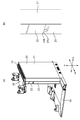
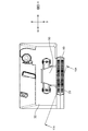
通常時は、図5(a)および(b)ならびに図10(a)および(b)に示すように、スイッチ扉22は、閉扉状態である。このとき、スイッチ扉22が閉じられているため、スライド部材23を上方に押しあげることはできない。したがって、スライド部材23の爪部23fの側面23fsは、装置本体10の突起部10pの側面10psに接触した状態である。
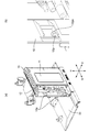
次いで、図6(a)および(b)ならびに図11(a)および(b)に示すように、スイッチ扉22をめくり上げて開扉状態にする。このとき、スイッチ窓部24内には、スイッチ延長部60が露出する。また、スイッチ扉22が開かれているため、スライド部材23を上方に押し上げることができる。
さらに、図7(a)および(b)ならびに図12(a)および(b)に示すように、スイッチ扉22は開扉状態のままで、スライド部材23の下端部23L(図18(b))に指をかけてスライド部材23を上方に押し上げると、スライド部材23の爪部23fの側面23fsと装置本体10の突起部10pの側面10psとの接触が解除された状態となる。
さらにまた、図7(a)および(b)ならびに図12(a)および(b)に示す状態で、カバー20を幅方向W(本例においては前方から見て右方向)にスライドさせると、装置本体10の凹部10s(図4参照)へのカバー20の係合爪20f(図4参照)の挿入が解除され、カバー20を取り外すことができる。
以上のようにして、カバー20が装置本体10から取り外される。
次に、図13~図20を参照して、カバー20の構造について説明する。
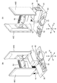
図13に示すように、カバー20は、カバー本体21、扉保持部25、スイッチ扉22、スイッチ延長部60およびスライド部材23から構成されている。図4を参照して前述したように、カバー本体21には、係合爪20fが5箇所に設けられ、下端に2箇所の凸部20pが設けられている。
図14(a)~(f)に示す扉保持部25は、カバー本体21に組み付けられる。扉保持部25には、スイッチ扉22の後述する回動軸を挿通するための2箇所の孔部25xが設けられている。
図15(a)~(f)に示すスイッチ扉22は、カバー本体21に組み付けられた扉保持部25によって回動自在に保持される。スイッチ扉22の回動軸22xは、扉保持部25の孔部25xに挿通される。スイッチ扉22を回動軸22xを中心として、回動的に開扉可能である。
図16(a)~(f)ならびに図17(a)および(b)に示すように、スイッチ延長部60は、カバー本体21に組み付けられる。スイッチ延長部60は、保持部61、可動部62および圧縮コイルばね66によって構成されている。カバー本体21のスイッチ窓部24(図6(b)、図11(b))から制御ボックス11の電源スイッチ12(図3、図4)を押下できるように、可動部62はL字型を呈しており、電源スイッチ12を表す記号が設けられている操作面63の中心線と、電源スイッチ12の中心線は異なる位置にある。店員等が操作面63を押すと、可動部62が移動して、接触面64が制御ボックス11の電源スイッチ12に接触して、電源スイッチ12が押下される。接触面64には、電源スイッチ12を押し過ぎないように4箇所にストッパ65が設けられている。
図18(a)~(f)ならびに図19(a)および(b)に示すように、スライド部材23は、2箇所に下方向に突出したフック状の爪部23fが設けられている。スライド部材23の爪部23fが設けられている側の3箇所には、カバー本体21の対応する孔部に挿入される突起23pが設けられている。そのうちの2箇所は、爪部23fと重複する位置にある。スライド部材23の爪部23fが設けられている側ではない側の3箇所には、カバー本体21の対応する孔部に挿入される突起23tが設けられている。
さらに図20、図21(a)および(b)ならびに図22(a)~(d)をも参照すると、スライド部材23には、前述したように、スライド部材23に3箇所ずつの突起23p、突起23tが設けられている。一方、カバー本体21には、スライド部材23の突起23p、突起23tに対応する孔部21d、孔部21gが設けられている。スライド部材23の突起23p、突起23tがカバー本体21の孔部21d、孔部21gに挿入されて、カバー本体21にスライド部材23が組み付けられる。図22(c)、図22(d)から分かるように、カバー本体21の孔部21d、孔部21gに挿入されたスライド部材23の突起23p、突起23tの端部はフック状を呈しているため、スライド部材23がカバー本体21から外れることはない。スライド部材23は、カバー本体21の孔部21d、孔部21gと挿入されるスライド部材23の突起23p、突起23tとの寸法の差分だけ、移動可能である。
図23(a)および(b)を参照すると、本POS端末装置は、基台部30上の店員用表示部40S側に、付属装置として、レシートプリンタ70とバーコードリーダ80とを有している。また、基台部30上の顧客用表示部40C側には、リーダライタ用台座32が取り付けられており、必要に応じて、付属装置としてのリーダライタ(図示せず)が搭載される。尚、図23(a)および(b)中、付属装置と装置本体10とを接続するための接続ケーブルは、図示を省略している。
尚、以上説明した実施形態においては、スイッチ延長部60をカバー20に組み付けているが、スイッチ延長部をカバーではなく、制御ボックスに組み付けるようにしてもよい。また、スイッチ延長部を制御ボックスの外側に付加するのではなく、制御ボックスに内蔵するものとしてもよい。さらに、制御ボックスが、スイッチ延長部を有さず、スイッチ窓部を介して電源スイッチ自体を押下できる位置に備えるものであってもよい。
以上の説明から明らかなように、本発明による電子機器は、カバーを工具なしで容易に取り外すことが可能である一方、カバーを取り外すための操作ツマミが、電子機器の外部に露出していないばかりか、操作ツマミ自体が存在しない。また、カバーを取り外すためには、スイッチ扉を開いた上で、さらにスライド部材を押し上げた状態を維持しつつ、カバーをスライドさせるという操作、即ち、複数種類の操作を行う必要がある。このため、顧客等の電子機器の操作を許されてない者によるイタズラの虞が低減される。
さらに、スイッチ扉は、電子機器の操作を許されてない者によるイタズラを受けたくない電源スイッチを覆い隠すための部材であるだけではなく、カバーを取り外すために操作が必要なロック部材の類でもある。このため、電源スイッチを覆い隠すための部材と、カバーのロック部材とを個別に設ける場合に比べ、コスト削減を図ることができる。
さらにまた、スライド部材も、スイッチ扉と同様に、カバーを取り外すために操作が必要なロック部材の類であるだけではなく、カバー本体と共に装置本体を覆い隠す外皮部材としての機能をも奏する。このため、外皮部材と、カバーのロック部材とを個別に設ける場合に比べてコスト削減を図ることができる。また、電子機器の操作を許されてない者がスライド部材を見ても、ロック部材だと気が付く可能性は低いと考えられる。
また、この出願は、2017年9月6日に出願された日本出願特願第2017-170909号を基礎とする優先権を主張し、その開示の全てをここに取り込む。
10 装置本体
10p 突起部
10ps 側面
11 制御ボックス
12 電源スイッチ
20 カバー
21 カバー本体
22 スイッチ扉
22L 下端部
23 スライド部材
23f 爪部
23fs 側面
23L 下端部
23U 上端部
24 スイッチ窓部
30 基台部
32 リーダライタ用台座
33 バーコードリーダ載置部
35 ケーブル導出部
40C 顧客用ディスプレイ
40S 店員用ディスプレイ
50 ディスプレイ支持部
52C ヒンジ部
52S ヒンジ部
60 スイッチ延長部
70 レシートプリンタ
80 バーコードリーダ
10p 突起部
10ps 側面
11 制御ボックス
12 電源スイッチ
20 カバー
21 カバー本体
22 スイッチ扉
22L 下端部
23 スライド部材
23f 爪部
23fs 側面
23L 下端部
23U 上端部
24 スイッチ窓部
30 基台部
32 リーダライタ用台座
33 バーコードリーダ載置部
35 ケーブル導出部
40C 顧客用ディスプレイ
40S 店員用ディスプレイ
50 ディスプレイ支持部
52C ヒンジ部
52S ヒンジ部
60 スイッチ延長部
70 レシートプリンタ
80 バーコードリーダ
Claims (10)
- 電源スイッチを有する装置本体と、
前記装置本体の、前記電源スイッチを含む少なくとも一部を覆うカバーと、を有し、
前記カバーは、
幅方向または奥行方向にスライドして取り外し可能に前記装置本体に取り付けられたカバー本体と、
前記カバー本体に設けられ、前記電源スイッチを操作するために該電源スイッチを前記カバーの外部と連通させるスイッチ窓部と、
上方に向かって開扉可能に前記カバー本体に取り付けられ、前記スイッチ窓部を覆蓋するスイッチ扉と、
下方の第1の位置から上方の第2の位置に向かってスライド可能に前記カバー本体の前記スイッチ扉に隣接して取り付けられたスライド部材と、を有し、
前記装置本体は、上方に向かって突出する突起部を有し、
前記スライド部材は、下方に向かって突出する爪部を有し、
前記スイッチ扉の下端部は、
前記スイッチ扉の閉扉時は、前記第1の位置にある前記スライド部材の上端部に接触する一方、
前記スイッチ扉の開扉時は、前記スライド部材の上端部への接触を解除し、
前記スライド部材の前記爪部の前記幅方向または前記奥行方向における側面は、
前記スライド部材が前記第1の位置にあるときは、前記装置本体の前記突起部の前記幅方向または前記奥行方向における側面に接触する一方、
前記スライド部材が前記第2の位置にあるときは、前記装置本体の前記突起部の前記幅方向または前記奥行方向における側面への接触を解除する、電子機器。 - 前記スイッチ扉は、前記奥行方向または前記幅方向に延在する回転軸を中心として斜め上方に向かって開扉可能に前記カバー本体に取り付けられ、
前記スライド部材は、下方の前記第1の位置から上方の前記第2の位置に向かってスライド可能に前記カバー本体の前記スイッチ扉の下側に取り付けられている、請求項1に記載の電子機器。 - 前記カバーは、前記スイッチ窓部と前記電源スイッチとの間に延在し、かつ、該電源スイッチの操作方向に変位可能に前記カバー本体に取り付けられたスイッチ延長部をさらに有し、
前記スイッチ延長部は、前記スイッチ扉の開扉時に、前記電源スイッチの前記カバー外部からの操作を可能とする、請求項1または2に記載の電子機器。 - 前記スイッチ扉は、閉扉状態となるように付勢され、
前記スライド部材は、前記第1の位置となるように付勢されている、請求項1乃至3のいずれか一項に記載の電子機器。 - 前記スイッチ扉は、自重によって閉扉状態となるように付勢され、
前記スライド部材は、自重によって前記第1の位置となるように付勢されている、請求項4に記載の電子機器。 - 前記装置本体と他の電子機器とを電気的に接続するためのケーブルを導出するケーブル導出部をさらに有している、請求項1乃至5のいずれか一項に記載の電子機器。
- 請求項1乃至6のいずれか一項に記載の電子機器は、情報処理装置であり、
前記装置本体は、情報処理を行う制御部をさらに有し、
前記制御部は、
情報を演算処理する演算部と、
少なくともプログラムソフトウエアを記憶する記憶部と、
演算処理前の情報を入力する一方、演算処理後の情報を出力する情報入出力部と、を有し、
前記演算部は、前記記憶部に記憶された前記プログラムソウトウエアに基づいて演算処理を行う、情報処理装置。 - 請求項7に記載の情報処理装置は、POS端末装置であり、
店員用ディスプレイと、顧客用ディスプレイと、をさらに有する、POS端末装置。 - レシートプリンタと、バーコードリーダと、をさらに有する、請求項8に記載のPOS端末装置。
- 請求項1乃至6のいずれか一項に記載の電子機器の、カバーの取り外し方法であって、
前記スイッチ扉を開扉することによって前記スライド部材の上端部への接触を解除することにより、前記スライド部材の前記第2の位置へのスライドを許可する工程と、
前記スライド部材を前記第2の位置に向かってスライドさせることによって前記スライド部材の前記爪部の前記側面の前記装置本体の前記突起部の前記側面に対する接触を解除することにより、前記カバー本体の前記幅方向または前記奥行方向のスライドを許可する工程と、
前記カバー本体を前記幅方向または前記奥行方向にスライドして前記装置本体から取り外す工程と、を有する、電子機器のカバーの取り外し方法。
Priority Applications (2)
| Application Number | Priority Date | Filing Date | Title |
|---|---|---|---|
| CN201880057058.6A CN111095369B (zh) | 2017-09-06 | 2018-08-03 | 电子装置、信息处理设备和pos终端 |
| US16/642,252 US11176532B2 (en) | 2017-09-06 | 2018-08-03 | Electronic device, information processing apparatus, and POS terminal |
Applications Claiming Priority (2)
| Application Number | Priority Date | Filing Date | Title |
|---|---|---|---|
| JP2017170909A JP6440218B1 (ja) | 2017-09-06 | 2017-09-06 | 電子機器、情報処理装置およびpos端末装置 |
| JP2017-170909 | 2017-09-06 |
Publications (1)
| Publication Number | Publication Date |
|---|---|
| WO2019049574A1 true WO2019049574A1 (ja) | 2019-03-14 |
Family
ID=64668480
Family Applications (1)
| Application Number | Title | Priority Date | Filing Date |
|---|---|---|---|
| PCT/JP2018/029223 Ceased WO2019049574A1 (ja) | 2017-09-06 | 2018-08-03 | 電子機器、情報処理装置およびpos端末装置 |
Country Status (4)
| Country | Link |
|---|---|
| US (1) | US11176532B2 (ja) |
| JP (1) | JP6440218B1 (ja) |
| CN (1) | CN111095369B (ja) |
| WO (1) | WO2019049574A1 (ja) |
Families Citing this family (1)
| Publication number | Priority date | Publication date | Assignee | Title |
|---|---|---|---|---|
| WO2022065576A1 (ko) * | 2020-09-23 | 2022-03-31 | 효성티앤에스 주식회사 | 빌트인 디지털 데스크 |
Citations (5)
| Publication number | Priority date | Publication date | Assignee | Title |
|---|---|---|---|---|
| JPH10208574A (ja) * | 1997-01-21 | 1998-08-07 | Sony Corp | スイッチ装置 |
| JP2011222730A (ja) * | 2010-04-09 | 2011-11-04 | Sony Corp | 電子機器ユニットの着脱機構、電子機器ユニット、電源ユニット、および電子機器装置 |
| JP2012178743A (ja) * | 2011-02-25 | 2012-09-13 | Kyocera Document Solutions Inc | 原稿読取装置及びその原稿読取装置を備える画像形成装置 |
| JP2013022136A (ja) * | 2011-07-19 | 2013-02-04 | Daito Giken:Kk | 遊技台 |
| JP2014143364A (ja) * | 2013-01-25 | 2014-08-07 | Fujitsu Frontech Ltd | 端末装置 |
Family Cites Families (21)
| Publication number | Priority date | Publication date | Assignee | Title |
|---|---|---|---|---|
| US5594617A (en) * | 1994-12-06 | 1997-01-14 | Digital Equipment Corporation | Rotating battery hinge for a notebook computer |
| US5933812A (en) * | 1995-04-12 | 1999-08-03 | Verifone Inc. | Portable transaction terminal system |
| JP3606498B2 (ja) * | 1996-04-26 | 2005-01-05 | 三菱電機株式会社 | 携帯情報端末装置 |
| JP2001044656A (ja) * | 1999-05-24 | 2001-02-16 | Nec Corp | 電子機器筐体 |
| US6629636B1 (en) * | 1999-12-20 | 2003-10-07 | Matsushita Electric Industrial Co., Ltd. | Sales transaction terminal device |
| US6367896B1 (en) | 2000-06-07 | 2002-04-09 | Hon Hai Precision Ind. Co., Ltd. | Computer enclosure with releasable interlocking mechanism between cover and chassis |
| JP4096642B2 (ja) | 2002-06-21 | 2008-06-04 | セイコーエプソン株式会社 | 画像データの処理方法、および、画像データ処理システム |
| US6735075B1 (en) | 2003-04-11 | 2004-05-11 | D&C Technology Co., Ltd. | Removable casing for memory card |
| JP4640843B2 (ja) | 2004-08-19 | 2011-03-02 | 富士通株式会社 | コンピュータおよびコンピュータ用筐体 |
| DE602006000122T2 (de) * | 2005-02-28 | 2008-06-26 | Seiko Epson Corp. | Datenverarbeitungsgerät |
| JP4741564B2 (ja) * | 2007-10-12 | 2011-08-03 | 東芝テック株式会社 | クランプ部材及びクランプ方法 |
| JP2009098705A (ja) * | 2007-10-12 | 2009-05-07 | Toshiba Tec Corp | 電子装置及び電子装置内部へのアクセス方法 |
| CN101631437B (zh) | 2008-07-15 | 2013-05-01 | 明泰科技股份有限公司 | 电子装置的壳体 |
| JP4824093B2 (ja) | 2009-02-12 | 2011-11-24 | 東芝テック株式会社 | 商品販売データ処理装置 |
| JP4949446B2 (ja) * | 2009-08-27 | 2012-06-06 | 東芝テック株式会社 | 感電防止機構及び感電防止機構を備える情報処理端末 |
| WO2011080117A1 (en) | 2009-12-31 | 2011-07-07 | Arcelik Anonim Sirketi | A cash register |
| JP5513168B2 (ja) * | 2010-02-26 | 2014-06-04 | パナソニック株式会社 | 電子機器 |
| CN102802375B (zh) * | 2011-05-24 | 2016-08-03 | 扬州海通电子科技有限公司 | 具有电源模组的电子装置 |
| JP5219005B2 (ja) | 2011-10-28 | 2013-06-26 | Necインフロンティア株式会社 | Pos端末装置 |
| FR3010984B1 (fr) | 2013-09-24 | 2016-02-26 | Fillon Technologies | Couvercle pour la fermeture de boite et ensemble comprenant une boite et un couvercle du type precite |
| WO2017115507A1 (ja) * | 2015-12-28 | 2017-07-06 | ソニー株式会社 | 情報処理装置、情報処理方法、プログラム、及び情報処理システム |
-
2017
- 2017-09-06 JP JP2017170909A patent/JP6440218B1/ja active Active
-
2018
- 2018-08-03 WO PCT/JP2018/029223 patent/WO2019049574A1/ja not_active Ceased
- 2018-08-03 CN CN201880057058.6A patent/CN111095369B/zh active Active
- 2018-08-03 US US16/642,252 patent/US11176532B2/en active Active
Patent Citations (5)
| Publication number | Priority date | Publication date | Assignee | Title |
|---|---|---|---|---|
| JPH10208574A (ja) * | 1997-01-21 | 1998-08-07 | Sony Corp | スイッチ装置 |
| JP2011222730A (ja) * | 2010-04-09 | 2011-11-04 | Sony Corp | 電子機器ユニットの着脱機構、電子機器ユニット、電源ユニット、および電子機器装置 |
| JP2012178743A (ja) * | 2011-02-25 | 2012-09-13 | Kyocera Document Solutions Inc | 原稿読取装置及びその原稿読取装置を備える画像形成装置 |
| JP2013022136A (ja) * | 2011-07-19 | 2013-02-04 | Daito Giken:Kk | 遊技台 |
| JP2014143364A (ja) * | 2013-01-25 | 2014-08-07 | Fujitsu Frontech Ltd | 端末装置 |
Also Published As
| Publication number | Publication date |
|---|---|
| CN111095369B (zh) | 2021-10-26 |
| US20210073773A1 (en) | 2021-03-11 |
| US11176532B2 (en) | 2021-11-16 |
| JP6440218B1 (ja) | 2018-12-19 |
| CN111095369A (zh) | 2020-05-01 |
| JP2019046344A (ja) | 2019-03-22 |
Similar Documents
| Publication | Publication Date | Title |
|---|---|---|
| US11377884B2 (en) | Lock device | |
| EP3531233B1 (en) | Coupling mechanism for coupling electronic device | |
| JP2021506489A (ja) | カバー形材を備えた引出し側壁 | |
| JP5027449B2 (ja) | 電子機器カバーのロック構造 | |
| JP6025228B1 (ja) | ディスプレイ装置 | |
| JP2019046344A (ja) | 電子機器、情報処理装置およびpos端末装置 | |
| CN107293454B (zh) | 电路断路器 | |
| JP4487790B2 (ja) | 電源スイッチの誤操作防止装置 | |
| JP6829625B2 (ja) | 発信機 | |
| US20200346588A1 (en) | Method for mounting and dismounting a telematics unit, telematics unit and module of a vehicle | |
| JP5095732B2 (ja) | 安全装置および安全装置の組み立て方法 | |
| JP4722603B2 (ja) | ゲーム機の施錠装置 | |
| JP5455433B2 (ja) | 電気電子機器用キャビネットの蝶番 | |
| EP3070730B1 (en) | Fuse holder base | |
| JP6330940B2 (ja) | 押ボタンスイッチおよびその押ボタンスイッチを備えた操作機器 | |
| JP4994980B2 (ja) | 住宅用分電盤 | |
| JP2006218034A (ja) | ゲーム機の施錠装置 | |
| JP4955479B2 (ja) | スイッチボタン取付構造 | |
| JP2022160912A (ja) | 通信機器の設置構造 | |
| JP5809113B2 (ja) | ゲーム機の施錠装置 | |
| JP4953958B2 (ja) | ゲーム機の施錠装置 | |
| KR20130050006A (ko) | 휴대용 단말기의 키패드 체결장치 | |
| KR101204202B1 (ko) | 컴퓨터의 프론트패널 결합구조 | |
| KR102085021B1 (ko) | 차량용 창문 잠금장치 | |
| JP2003152349A (ja) | 電子機器 |
Legal Events
| Date | Code | Title | Description |
|---|---|---|---|
| 121 | Ep: the epo has been informed by wipo that ep was designated in this application |
Ref document number: 18854015 Country of ref document: EP Kind code of ref document: A1 |
|
| NENP | Non-entry into the national phase |
Ref country code: DE |
|
| 122 | Ep: pct application non-entry in european phase |
Ref document number: 18854015 Country of ref document: EP Kind code of ref document: A1 |