WO2019044950A1 - 動力伝達装置 - Google Patents
動力伝達装置 Download PDFInfo
- Publication number
- WO2019044950A1 WO2019044950A1 PCT/JP2018/032061 JP2018032061W WO2019044950A1 WO 2019044950 A1 WO2019044950 A1 WO 2019044950A1 JP 2018032061 W JP2018032061 W JP 2018032061W WO 2019044950 A1 WO2019044950 A1 WO 2019044950A1
- Authority
- WO
- WIPO (PCT)
- Prior art keywords
- clutch
- cam
- clutch plate
- pressure
- power transmission
- Prior art date
Links
- 230000005540 biological transmission Effects 0.000 title claims abstract description 112
- 230000013011 mating Effects 0.000 claims description 8
- 230000002093 peripheral effect Effects 0.000 description 6
- 238000010586 diagram Methods 0.000 description 5
- 238000013459 approach Methods 0.000 description 4
- 230000000694 effects Effects 0.000 description 2
- 238000003780 insertion Methods 0.000 description 2
- 230000037431 insertion Effects 0.000 description 2
- 238000005096 rolling process Methods 0.000 description 2
- 229910000831 Steel Inorganic materials 0.000 description 1
- 238000005452 bending Methods 0.000 description 1
- 238000000926 separation method Methods 0.000 description 1
- 239000010959 steel Substances 0.000 description 1
Images


Classifications
-
- F—MECHANICAL ENGINEERING; LIGHTING; HEATING; WEAPONS; BLASTING
- F16—ENGINEERING ELEMENTS AND UNITS; GENERAL MEASURES FOR PRODUCING AND MAINTAINING EFFECTIVE FUNCTIONING OF MACHINES OR INSTALLATIONS; THERMAL INSULATION IN GENERAL
- F16D—COUPLINGS FOR TRANSMITTING ROTATION; CLUTCHES; BRAKES
- F16D43/00—Automatic clutches
- F16D43/02—Automatic clutches actuated entirely mechanically
- F16D43/22—Automatic clutches actuated entirely mechanically controlled by both speed and torque
-
- F—MECHANICAL ENGINEERING; LIGHTING; HEATING; WEAPONS; BLASTING
- F16—ENGINEERING ELEMENTS AND UNITS; GENERAL MEASURES FOR PRODUCING AND MAINTAINING EFFECTIVE FUNCTIONING OF MACHINES OR INSTALLATIONS; THERMAL INSULATION IN GENERAL
- F16D—COUPLINGS FOR TRANSMITTING ROTATION; CLUTCHES; BRAKES
- F16D11/00—Clutches in which the members have interengaging parts
-
- F—MECHANICAL ENGINEERING; LIGHTING; HEATING; WEAPONS; BLASTING
- F16—ENGINEERING ELEMENTS AND UNITS; GENERAL MEASURES FOR PRODUCING AND MAINTAINING EFFECTIVE FUNCTIONING OF MACHINES OR INSTALLATIONS; THERMAL INSULATION IN GENERAL
- F16D—COUPLINGS FOR TRANSMITTING ROTATION; CLUTCHES; BRAKES
- F16D13/00—Friction clutches
- F16D13/22—Friction clutches with axially-movable clutching members
- F16D13/38—Friction clutches with axially-movable clutching members with flat clutching surfaces, e.g. discs
- F16D13/52—Clutches with multiple lamellae ; Clutches in which three or more axially moveable members are fixed alternately to the shafts to be coupled and are pressed from one side towards an axially-located member
- F16D13/54—Clutches with multiple lamellae ; Clutches in which three or more axially moveable members are fixed alternately to the shafts to be coupled and are pressed from one side towards an axially-located member with means for increasing the effective force between the actuating sleeve or equivalent member and the pressure member
-
- F—MECHANICAL ENGINEERING; LIGHTING; HEATING; WEAPONS; BLASTING
- F16—ENGINEERING ELEMENTS AND UNITS; GENERAL MEASURES FOR PRODUCING AND MAINTAINING EFFECTIVE FUNCTIONING OF MACHINES OR INSTALLATIONS; THERMAL INSULATION IN GENERAL
- F16D—COUPLINGS FOR TRANSMITTING ROTATION; CLUTCHES; BRAKES
- F16D19/00—Clutches with mechanically-actuated clutching members not otherwise provided for
-
- F—MECHANICAL ENGINEERING; LIGHTING; HEATING; WEAPONS; BLASTING
- F16—ENGINEERING ELEMENTS AND UNITS; GENERAL MEASURES FOR PRODUCING AND MAINTAINING EFFECTIVE FUNCTIONING OF MACHINES OR INSTALLATIONS; THERMAL INSULATION IN GENERAL
- F16D—COUPLINGS FOR TRANSMITTING ROTATION; CLUTCHES; BRAKES
- F16D21/00—Systems comprising a plurality of actuated clutches
- F16D21/08—Serially-arranged clutches interconnecting two shafts only when all the clutches are engaged
-
- F—MECHANICAL ENGINEERING; LIGHTING; HEATING; WEAPONS; BLASTING
- F16—ENGINEERING ELEMENTS AND UNITS; GENERAL MEASURES FOR PRODUCING AND MAINTAINING EFFECTIVE FUNCTIONING OF MACHINES OR INSTALLATIONS; THERMAL INSULATION IN GENERAL
- F16D—COUPLINGS FOR TRANSMITTING ROTATION; CLUTCHES; BRAKES
- F16D25/00—Fluid-actuated clutches
- F16D25/06—Fluid-actuated clutches in which the fluid actuates a piston incorporated in, i.e. rotating with the clutch
- F16D25/062—Fluid-actuated clutches in which the fluid actuates a piston incorporated in, i.e. rotating with the clutch the clutch having friction surfaces
- F16D25/063—Fluid-actuated clutches in which the fluid actuates a piston incorporated in, i.e. rotating with the clutch the clutch having friction surfaces with clutch members exclusively moving axially
- F16D25/0635—Fluid-actuated clutches in which the fluid actuates a piston incorporated in, i.e. rotating with the clutch the clutch having friction surfaces with clutch members exclusively moving axially with flat friction surfaces, e.g. discs
- F16D25/0638—Fluid-actuated clutches in which the fluid actuates a piston incorporated in, i.e. rotating with the clutch the clutch having friction surfaces with clutch members exclusively moving axially with flat friction surfaces, e.g. discs with more than two discs, e.g. multiple lamellae
-
- F—MECHANICAL ENGINEERING; LIGHTING; HEATING; WEAPONS; BLASTING
- F16—ENGINEERING ELEMENTS AND UNITS; GENERAL MEASURES FOR PRODUCING AND MAINTAINING EFFECTIVE FUNCTIONING OF MACHINES OR INSTALLATIONS; THERMAL INSULATION IN GENERAL
- F16D—COUPLINGS FOR TRANSMITTING ROTATION; CLUTCHES; BRAKES
- F16D43/00—Automatic clutches
- F16D43/02—Automatic clutches actuated entirely mechanically
- F16D43/04—Automatic clutches actuated entirely mechanically controlled by angular speed
- F16D43/06—Automatic clutches actuated entirely mechanically controlled by angular speed with centrifugal masses actuating axially a movable pressure ring or the like
- F16D43/08—Automatic clutches actuated entirely mechanically controlled by angular speed with centrifugal masses actuating axially a movable pressure ring or the like the pressure ring actuating friction plates, cones or similar axially-movable friction surfaces
- F16D43/12—Automatic clutches actuated entirely mechanically controlled by angular speed with centrifugal masses actuating axially a movable pressure ring or the like the pressure ring actuating friction plates, cones or similar axially-movable friction surfaces the centrifugal masses acting on, or forming a part of, an actuating mechanism by which the pressure ring can also be actuated independently of the masses
-
- F—MECHANICAL ENGINEERING; LIGHTING; HEATING; WEAPONS; BLASTING
- F16—ENGINEERING ELEMENTS AND UNITS; GENERAL MEASURES FOR PRODUCING AND MAINTAINING EFFECTIVE FUNCTIONING OF MACHINES OR INSTALLATIONS; THERMAL INSULATION IN GENERAL
- F16D—COUPLINGS FOR TRANSMITTING ROTATION; CLUTCHES; BRAKES
- F16D43/00—Automatic clutches
- F16D43/02—Automatic clutches actuated entirely mechanically
- F16D43/20—Automatic clutches actuated entirely mechanically controlled by torque, e.g. overload-release clutches, slip-clutches with means by which torque varies the clutching pressure
- F16D43/21—Automatic clutches actuated entirely mechanically controlled by torque, e.g. overload-release clutches, slip-clutches with means by which torque varies the clutching pressure with friction members
- F16D43/213—Automatic clutches actuated entirely mechanically controlled by torque, e.g. overload-release clutches, slip-clutches with means by which torque varies the clutching pressure with friction members with axially applied torque-limiting friction surfaces
- F16D43/215—Automatic clutches actuated entirely mechanically controlled by torque, e.g. overload-release clutches, slip-clutches with means by which torque varies the clutching pressure with friction members with axially applied torque-limiting friction surfaces with flat friction surfaces, e.g. discs
- F16D43/216—Automatic clutches actuated entirely mechanically controlled by torque, e.g. overload-release clutches, slip-clutches with means by which torque varies the clutching pressure with friction members with axially applied torque-limiting friction surfaces with flat friction surfaces, e.g. discs with multiple lamellae
-
- F—MECHANICAL ENGINEERING; LIGHTING; HEATING; WEAPONS; BLASTING
- F16—ENGINEERING ELEMENTS AND UNITS; GENERAL MEASURES FOR PRODUCING AND MAINTAINING EFFECTIVE FUNCTIONING OF MACHINES OR INSTALLATIONS; THERMAL INSULATION IN GENERAL
- F16D—COUPLINGS FOR TRANSMITTING ROTATION; CLUTCHES; BRAKES
- F16D13/00—Friction clutches
- F16D13/22—Friction clutches with axially-movable clutching members
- F16D13/38—Friction clutches with axially-movable clutching members with flat clutching surfaces, e.g. discs
- F16D13/52—Clutches with multiple lamellae ; Clutches in which three or more axially moveable members are fixed alternately to the shafts to be coupled and are pressed from one side towards an axially-located member
- F16D13/54—Clutches with multiple lamellae ; Clutches in which three or more axially moveable members are fixed alternately to the shafts to be coupled and are pressed from one side towards an axially-located member with means for increasing the effective force between the actuating sleeve or equivalent member and the pressure member
- F16D13/56—Clutches with multiple lamellae ; Clutches in which three or more axially moveable members are fixed alternately to the shafts to be coupled and are pressed from one side towards an axially-located member with means for increasing the effective force between the actuating sleeve or equivalent member and the pressure member in which the clutching pressure is produced by springs only
- F16D2013/565—Clutches with multiple lamellae ; Clutches in which three or more axially moveable members are fixed alternately to the shafts to be coupled and are pressed from one side towards an axially-located member with means for increasing the effective force between the actuating sleeve or equivalent member and the pressure member in which the clutching pressure is produced by springs only with means for releasing the clutch pressure in case of back torque
-
- F—MECHANICAL ENGINEERING; LIGHTING; HEATING; WEAPONS; BLASTING
- F16—ENGINEERING ELEMENTS AND UNITS; GENERAL MEASURES FOR PRODUCING AND MAINTAINING EFFECTIVE FUNCTIONING OF MACHINES OR INSTALLATIONS; THERMAL INSULATION IN GENERAL
- F16D—COUPLINGS FOR TRANSMITTING ROTATION; CLUTCHES; BRAKES
- F16D23/00—Details of mechanically-actuated clutches not specific for one distinct type
- F16D23/12—Mechanical clutch-actuating mechanisms arranged outside the clutch as such
- F16D2023/123—Clutch actuation by cams, ramps or ball-screw mechanisms
-
- F—MECHANICAL ENGINEERING; LIGHTING; HEATING; WEAPONS; BLASTING
- F16—ENGINEERING ELEMENTS AND UNITS; GENERAL MEASURES FOR PRODUCING AND MAINTAINING EFFECTIVE FUNCTIONING OF MACHINES OR INSTALLATIONS; THERMAL INSULATION IN GENERAL
- F16D—COUPLINGS FOR TRANSMITTING ROTATION; CLUTCHES; BRAKES
- F16D2300/00—Special features for couplings or clutches
- F16D2300/24—Concentric actuation rods, e.g. actuation rods extending concentrically through a shaft
Definitions
- the present invention relates to a power transmission device that can optionally transmit or interrupt the rotational force of an input member to an output member.
- a power transmission device provided in a motorcycle is for arbitrarily transmitting or interrupting a driving force of an engine to a transmission and driving wheels, and an input member connected to the engine side, a transmission and a driving wheel side, and the like. It has the output member connected, the clutch member connected with the output member, and the pressure member which can be approached or separated with respect to the clutch member, and by driving the pressure member close to the clutch member.
- the side clutch plate and the driven side clutch plate are brought into pressure contact to transmit power, and the pressure member is separated from the clutch member to release the pressure contact force between the drive side clutch plate and the driven side clutch plate In order to block the transmission of the power.
- the drive-side clutch plate and the driven plate are moved by moving from the inner diameter side position of the groove to the outer diameter side position by centrifugal force accompanying rotation of the clutch housing.
- a weight member coil spring 16
- the centrifugal force can be applied to the weight member by the rotation of the clutch housing with the drive of the engine, and the drive side clutch plate and the driven side clutch plate are brought into pressure contact with each other.
- the driving force of the engine can be transmitted to the wheels.
- the cam mechanism having the elongated hole 32 and the pin 30 is provided, and the cam formed of the elongated hole 32 and the pin 30 even when the weight member is at the inside diameter position.
- the present invention has been made in view of such circumstances.
- the pressure member When the pressure member is in the inoperative position, the rotational force on the wheel side is transmitted to the engine side by pressing the drive side clutch plate and the driven side clutch plate. It is an object of the present invention to provide a power transmission device capable of causing an engine brake and stably performing an operation by a weight member at the time of causing an engine brake.
- the invention according to claim 1 is formed alternately with a clutch housing which is rotated with an input member which is rotated by a driving force of an engine of a vehicle and to which a plurality of drive side clutch plates are attached and the drive side clutch plates of the clutch housing.
- a plurality of driven side clutch plates are attached, and a clutch member connected to an output member capable of rotating the wheels of the vehicle, the drive side clutch plate and the driven side clutch plate are brought into pressure contact with each other to drive the engine.
- a pressure member movable between positions and a radially extending groove portion of the clutch housing, and the clutch housing A weight member movable from an inner diameter side position to an outer diameter side position of the groove by centrifugal force accompanying rolling, and the pressure member as the weight member moves from the inner diameter side position to the outer diameter side position
- Power transmission device having an interlocking member capable of moving the inoperative position from the inoperative position to the operative position, wherein the clutch member is attached with a first clutch member coupled to the output member and the driven side clutch plate When rotational force is input to the first clutch member via the output member when the second clutch member and the pressure member are in the inoperative position, the second clutch member is moved to move the drive clutch A back torque transmitting cam capable of bringing a plate and a driven clutch plate into pressure contact
- the back torque transmitting cam is constituted by a cam surface integrally formed on each of the first clutch member and the second clutch member.
- the cam surfaces are formed on the mating surfaces of the first clutch member and the second clutch member.
- the cam surface is formed in a plurality along the annular shape of the driven clutch plate attached to the second clutch member. It features.
- the sloped surface formed on the first clutch member and the sloped surface formed on the pressure member are opposed to each other.
- For pressure contact assist for increasing the pressure contact force between the drive side clutch plate and the driven side clutch plate when the rotational force input to the input member can be transmitted to the output member It is characterized by having a cam.
- the invention according to claim 5 is the power transmission apparatus according to any one of claims 1 to 4, wherein the sloped surface formed on the first clutch member is opposed to the sloped surface formed on the pressure member.
- the back torque transmitting cam can move the second clutch member in the direction approaching the interlocking member to hold the abutment between the interlocking member and the weight member, so that the pressure can be reduced.
- the rotational force on the wheel side can be transmitted to the engine side by bringing the drive side clutch plate and the driven side clutch plate into pressure contact to produce an engine brake and produce an engine brake. It is possible to stably perform the operation by the weight member at the time of operation.
- the back torque transmitting cam is constituted by a cam surface integrally formed on each of the first clutch member and the second clutch member, and the cam surface is the first clutch member and the first clutch member. Since they are respectively formed on the mating surfaces of the two clutch members, it is possible to reliably and smoothly move the second clutch member by the back torque transmitting cam.
- a plurality of cam surfaces are formed along the annular shape of the driven side clutch plate attached to the second clutch member. Therefore, the driven side clutch is operated by the action of the back torque transmitting cam. A substantially equal pressing force can be applied to the plate, and the drive clutch plate and the driven clutch plate can be more efficiently brought into pressure contact with each other.
- the gradient surface formed on the first clutch member and the gradient surface formed on the pressure member are configured to face each other, and the rotational force input to the input member is transmitted to the output member Since the cam for pressure contact assist is provided to increase the pressure contact force between the drive side clutch plate and the driven side clutch plate when it is in the obtained state, the pressure contact assist is added to the pressure contact force accompanying the movement of the weight member by the centrifugal force.
- the pressing force by the cam can be applied, and the driving clutch plate and the driven clutch plate can be pressure-welded more smoothly and reliably.
- the gradient surface formed on the first clutch member and the gradient surface formed on the pressure member are configured to face each other, and the rotation of the output member exceeds the number of rotations of the input member. Since the cam for the back torque limiter which can release the pressure contact force between the drive side clutch plate and the driven side clutch plate when the clutch member and the pressure member relatively rotate, the weight member is at the outer diameter side position At the same time, excessive power can be prevented from being transmitted to the engine through the input member, and the back torque transmission cam is operated before the back torque limiter cam is activated. The operation by the back torque transmission cam can be reliably performed.
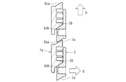
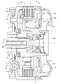
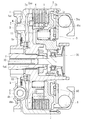
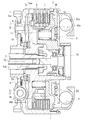
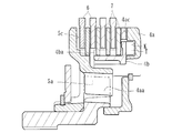
- An external view showing a power transmission device according to an embodiment of the present invention Longitudinal sectional view showing an internal configuration of the power transmission device Schematic diagram showing a pressure contact assist cam in the same power transmission device
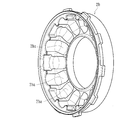
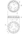
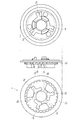
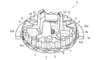
- the perspective view which shows the case part of the clutch housing in the same power transmission device The perspective view which shows the cover part of the clutch housing in the same power transmission device Three views showing the first clutch member in the power transmission device Three views showing the second clutch member in the same power transmission device Three views showing the pressure member in the same power transmission device
- the perspective view which shows the state before assembly of the 1st clutch member in the same power transmission device, the 2nd clutch member, and the pressure member The perspective view which shows the state before assembly of the 1st clutch member in the same power transmission device, the 2nd clutch member, and the pressure member
- the perspective view which shows the state after assembly of the 1st clutch member, the 2nd clutch member, and the pressure member in the same power transmission device Schematic diagram for explaining the action of the pressure contact assist cam in the power transmission device
- the power transmission device is disposed in a vehicle such as a two-wheeled vehicle and is for transmitting or interrupting the driving force of the engine to the transmission or the driving wheel side as shown in FIGS.
- a clutch housing 2 formed with an input gear 1 (input member) rotated by a driving force of an engine of a vehicle, a clutch member (a first clutch member 4a and a second clutch member 4b), and a clutch member (a first clutch member 4a and the second clutch member 4b), the pressure member 5 mounted on the right side in FIG.
- the plurality of drive side clutch plates 6 and the plurality of driven side clutch plates 7, and radial movement within the clutch housing 2 It consists mainly of a weight member 8 consisting of a movable steel ball member, an interlocking member 9 and an actuating member 10 which can be operated by manual operation or an actuator (not shown).
- reference symbol S denotes a spring damper
- reference symbol B1 denotes a roller bearing
- reference symbols B2 and B3 denote a thrust bearing.
- the input gear 1 is rotatable about the output shaft 3 when the driving force (rotational force) transmitted from the engine is input, and is connected to the clutch housing 2 by a rivet R or the like.
- the clutch housing 2 is formed of a cylindrical member opened at the right end in FIG. 2 and is connected to the input gear 1 with a housing 2a, and a cover 2b attached so as to close the opening of the housing 2a. It is configured to be able to rotate with the rotation of the input gear 1 by the driving force of the engine.
- the casing 2a of the clutch housing 2 is formed with a plurality of notches 2aa extending in the circumferential direction.
- a plurality of drive side clutch plates are engaged with the notches 2aa. 6 is attached.
- Each of the drive side clutch plates 6 is formed of a plate member formed in a substantially annular shape, and is configured to rotate along with the rotation of the clutch housing 2 and to slide in an axial direction (left and right direction in FIG. 2) There is.
- the cover 2b of the clutch housing 2 is formed with a plurality of grooves 2ba extending in the radial direction of the cover 2b on the bottom surface thereof.
- a weight member 8 is disposed in each of the groove portions 2ba, and when the clutch housing 2 is stopped (engine stopped or idling) and rotated at a low speed, the weight member 8 is located on the inner diameter side (FIG. 2). When the clutch housing 2 is rotated at a high speed, the weight member 8 is set to the outer diameter side position (the position shown in FIG. 21).
- the clutch members (the first clutch member 4a and the second clutch member 4b) are attached with a plurality of driven side clutch plates 7 alternately formed with the drive side clutch plates 6 of the clutch housing 2, and rotate the wheels of the vehicle. It is connected with the output shaft 3 (output member) to be obtained, and is constructed by assembling two members of a first clutch member 4a and a second clutch member 4b.
- the first clutch member 4a is a disc-like member having a flange surface 4ac formed over the peripheral portion, and the insertion hole 4ad formed at the center (see FIGS. 2 and 6).
- the output shaft 3 is inserted through the two-way gear, and the gears formed with each other are engaged and coupled in the rotational direction.
- the first clutch member 4a is formed with a slope surface 4aa which constitutes a pressure contact assist cam and a slope surface 4ab which constitutes a back torque limiter cam.
- the second clutch member 4b is an annular member, and the driven clutch plate 7 is spline-fitted to the spline fitting portion 4ba (see FIGS. 2 and 7) formed on the outer peripheral surface. It is configured to be attached at Then, as shown in FIGS. 9 to 11, the pressure member 5 is assembled to the clutch members (the first clutch member 4a and the second clutch member 4b), and the flange surface 5c of the pressure member 5 (see FIGS. A plurality of drive-side clutch plates 6 and a driven-side clutch plate 7 are alternately mounted in a stacked state between the) and the flange surface 4ac of the clutch member 4a (see FIGS. 2 and 6).
- the pressure member 5 is a disc-like member having a flange surface 5c formed over the peripheral portion, and the engine side is driven by pressing the drive side clutch plate 6 and the driven side clutch plate 7
- the driving force of the engine is transmitted to the wheels by releasing the pressure contact force between the driving side clutch plate 6 and the driven side clutch plate 7 so that the driving force of the driving force can be transmitted to the wheels (see FIG. 21). It is movable between an inoperative position (see FIG. 2) which can block the
- the spline fitting portion 4ba formed in the second clutch member 4b is integrated over substantially the entire outer peripheral side surface of the second clutch member 4b. And the shaft on the driven clutch plate 7 with respect to the second clutch member 4b by fitting the driven clutch plate 7 into the concave groove forming the spline fitting portion 4ba.
- the movement in the rotational direction is restricted while permitting the movement in the direction, and it is configured to be able to rotate together with the second clutch member 4b.
- the driven side clutch plates 7 are alternately stacked with the drive side clutch plates 6 so that the adjacent clutch plates 6 and 7 can press-contact or release the press-contact force. That is, both clutch plates 6, 7 are allowed to slide in the axial direction of the second clutch member 4b, and the pressure member 5 moves to the left in FIG. 2 and the flange surface 5c and the flange of the clutch member 4 are moved. When the surface 4ac approaches, both the clutch plates 6 and 7 are in pressure contact, and the rotational force of the clutch housing 2 is transmitted to the output shaft 3 via the second clutch member 4b and the first clutch member 4a. Moves to the right in FIG.
- the first clutch member 4 a is formed with the slopes 4 aa and 4 ab
- the pressure member 5 is formed with these slopes.
- Inclined surfaces 5a, 5b are formed to face the surfaces 4aa and 4ab. That is, the sloped surface 4 aa and the sloped surface 5 a are in contact with each other to form a pressure contact assist cam, and the sloped surface 4 ab and the sloped surface 5 b are in contact with each other to form a back torque limiter cam.
- the weight member 8 is disposed in a groove 2ba extending in the radial direction of the clutch housing 2 (in the present embodiment, the cover 2b), and the centrifugal force accompanying the rotation of the clutch housing 2 causes the inner diameter of the groove 2ba.
- the drive side clutch plate 6 and the driven side clutch plate 7 can be brought into pressure contact with each other. That is, the rolling surface (bottom surface) of the weight member 8 in the groove portion 2ba has an upward slope from the inner diameter side position to the outer diameter side position, and the weight member 8 is made of spring h when the clutch housing 2 is stopped.
- the spring h is bent until the separation distance between the drive side clutch plate 6 and the driven side clutch plate 7 becomes zero, and thereafter the drive side clutch plate 6 and the driven side clutch plate 7 are bent by bending the clutch spring 11. Is in pressure contact. Further, at the time of gear shifting, the spring h is expanded and the clutch spring 11 is contracted, so that the pressure member 5 is moved.
- the interlocking member 9 is an annular member disposed in the clutch housing 2 (cover portion 2b), and is engaged with and coupled to a groove formed in the inner peripheral surface of the cover portion 2b, and the clutch housing While being made rotatable with 2, it is made movable in the left-right direction in FIG.
- the interlocking member 9 moves to the left in FIG. 2 against the biasing force of the clutch spring 11 as the weight member 8 moves from the inner diameter side position to the outer diameter side position, and presses the pressure member 5. It is configured to be moved from the inoperative position to the operative position.
- the clutch spring 11 is composed of a coil spring interposed between the interlocking member 9 and the pressure member 5 and presses the pressure member 5 with the movement of the interlocking member 9 to drive the drive clutch plate 6 and the driven clutch plate. While being able to move the said pressure member 5 in the direction which press-contacts with 7, and at the time of the action
- the actuating member 10 is formed of a manually or actuator-operable member (see FIG. 2), and the pressure member in a direction (right side in FIG. 2) capable of releasing the pressure contact force between the drive clutch plate 6 and the driven clutch plate 7. 5 can be moved.
- the actuating member 10 is moved to the right in FIG. 2 by contact with the clutch pedal or clutch lever of the vehicle or the operation of an actuator to abut on the pressure member 5 to move the pressure member 5 in the same direction.
- the pressure contact force between the drive side clutch plate 6 and the driven side clutch plate 7 can be released to turn off the clutch (shut off the transmission of power).
- the second power transmission device when the rotational force is input to the first clutch member 4 a via the output shaft 3 (output member) when the pressure member 5 is in the inoperative position, the second power transmission device There is a back torque transmitting cam (cam surfaces K1, T1) capable of moving the clutch member 4b to bring the drive side clutch plate 6 and the driven side clutch plate 7 into pressure contact.
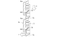
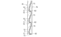
- a back torque transmitting cam is a cam surface (K1, T1) integrally formed on a mating surface (a mating surface at the time of combination) of the first clutch member 4a and the second clutch member 4b, as shown in FIGS. It consists of).
- a plurality of cam surfaces K1 are formed over the entire circumference on the inner diameter side (the mating surface with the second clutch member 4b) of the flange surface 4ac formed on the first clutch member 4a.
- the first clutch member 4a is formed on one end face of the groove portion K formed in a plurality of annular shapes along the peripheral edge portion of the first clutch member 4a. That is, in the first clutch member 4a, a plurality of groove portions K are formed along the circumferential direction, and as shown in FIGS. 18 and 19, one end face of each groove portion K is a sloped surface to be a back torque
- the cam surface K1 of the transmission cam is configured.
- the other end face of each groove portion K is a wall surface K2 extending in the axial direction (the left and right direction in FIGS. 18 and 19) of the first clutch member 4a, as shown in the figure.
- the cam surface T1 is, as shown in FIGS. 7 and 10, formed of a plurality of sloped surfaces formed on the entire bottom surface of the second clutch member 4b (the mating surface with the first clutch member 4a). It is formed on one end surface of the projecting portion T formed in a plurality of annular shapes along the bottom surface of the second clutch member 4b. That is, a plurality of protrusions T are formed on the second clutch member 4b in the circumferential direction, and as shown in FIGS. 18 and 19, one end face of each protrusion T is a sloped surface.
- the cam surface T1 of the back torque transmission cam is configured.
- the other end face of each protrusion T is a wall surface T2 extending in the axial direction (the left and right direction in FIGS. 18 and 19) of the second clutch member 4b, as shown in the figure.
- the pressing portion 4bb is formed on the extension of the spline fitting portion 4ba, and when the second clutch member 4b moves to the right in FIG.
- the driven-side clutch plate 7 on the leftmost side in the drawing is pressed in the same direction.
- the back torque transmitting cam moves the second clutch member 4b in a direction (right side in FIG. 2) closer to the interlocking member 9 so that the interlocking member 9 and the weight member 8 It is configured to be able to hold a contact. That is, when the back torque transmission cam operates to move the second clutch member 4b toward the right in FIG. 2, the drive clutch plate 6 and the driven clutch plate 7 are brought into pressure contact, and the pressure member 5 is shifted. Since the pressure is applied in the direction, the pressing force is transmitted to the interlocking member 9 through the clutch spring 11, and the abutment between the interlocking member 9 and the weight member 8 is held.
- the weight member 8 is then moved to the inner diameter side position and the outer diameter side position as the clutch housing 2 rotates.
- the interlocking member 9 may not be able to follow the movement even if it moves between the two, according to the present embodiment, the interlocking member 9 and the weight are also operated at the time of operation of the back torque transmission cam. Since the contact with the member 8 can be held, the interlocking member 9 can stably follow the movement of the weight member 8.
- a plurality of cam surfaces K1 and T1 constituting the back torque transmission cam according to the present embodiment are formed along the annular shape of the driven clutch plate 7 attached to the second clutch member 4b. That is, when the back torque transmitting cam operates, the cam surfaces K1 and T1 are formed along the projection shape (ring shape) of the driven side clutch plate 7 pressed by the pressing portion 4bb. As a result, the pressing portion 4bb can apply a substantially equal pressing force to the driven clutch plate 7 by the action of the back torque transmission cam, and the driving clutch plate 6 and the driven clutch plate can be more efficiently performed. 7 can be press-contacted.
- the back torque transmission cam (a cam formed of the cam surface K1 and the cam surface T1) according to the present embodiment operates the back torque limiter cam (a cam formed of the slope surface 4ab and the slope surface 5b). It is configured to be able to operate before. That is, the clearance (gap size) between the cam surface K1 and the cam surface T1 is set smaller than the clearance (gap size) between the slope surface 4ab and the slope surface 5b, and before the operation of the back torque limiter cam The back torque transmission cam can be operated.
- the back torque transmission cam (cam surface is formed on the first clutch member 4a and the second clutch member 4b and transmitted to the second clutch member 4b) A torque transmission portion that can be transmitted to the first clutch member 4a without via K1 and the cam surface T1), and the first clutch member 4a and the second clutch member 4b, respectively, and a back torque transmission cam (cam surface K1 and cam And a movement amount limiting unit for restricting the movement amount of the second clutch member 4b by the surface T1).
- the first clutch member 4a in the first clutch member 4a, a plurality of (three in the present embodiment) convex portions F are integrally formed at equal intervals in the circumferential direction, and the second clutch As shown in FIGS. 7 and 9, the member 4b is integrally formed with a protrusion G extending inward. Then, when the first clutch member 4a and the second clutch member 4b are assembled, as shown in FIGS.
- one convex portion F is in a state of being sandwiched between two projecting portions G,
- the side surface F1 of the portion F and the contact surface (first contact surface G1) of the one protrusion G face each other, and the contact surface of the other side F2 of the protrusion F and the other protrusion G (second It is comprised so that contact surface G2 may face.
- one side face F1 of the convex portion F formed on the first clutch member 4a and the first contact surface G1 of one projecting portion G formed on the second clutch member 4b are torques according to the present embodiment. It constitutes a transmission unit. That is, when the pressure member 5 moves to the operating position and the drive side clutch plate 6 and the driven side clutch plate 7 are pressed against each other to turn on the clutch (transmit the drive force), the wall surface K2 of the groove K in the back torque transmitting cam As shown in FIGS. 14 and 15, the one side F1 of the projection abuts on the first contact surface G1 of the projection G while the separated state (see FIG. 18) of the projection T is maintained. The rotational force of the second clutch member 4b can be transmitted to the first clutch member 4a.
- the other side face F2 of the convex portion F formed on the first clutch member 4a and the second contact surface G2 of the other projecting portion G formed on the second clutch member 4b are movement amounts according to the present embodiment. It constitutes the restriction part. That is, when rotational force is input to the first clutch member 4a via the output shaft 3 when the pressure member 5 is in the inoperative position, the first clutch member 4a and the second clutch member 4b relatively rotate. Therefore, the second clutch member 4b is moved by the action of the cams of the cam surface K1 of the groove K and the cam surface T1 of the projection T in the back torque transmission cam (see FIG. 19). Then, when the amount of movement reaches the set value, as shown in FIGS.
- the convex portion F is formed on the first clutch member 4a, and the projecting portion G is formed on the second clutch member 4b.
- the projecting portion G is formed on the first clutch member 4a.
- the convex portion F may be formed on the second clutch member 4b. In this case, one side F1 of the convex portion F formed on the second clutch member 4b and the first contact surface G1 of the one protruding portion G formed on the first clutch member 4a are torques according to the present embodiment.
- the other side F2 of the convex portion F formed on the second clutch member 4b and the second contact surface G2 of the other projecting portion G formed on the first clutch member 4a constitute the transmission portion, and the present embodiment
- the movement amount limiting unit according to the embodiment is configured.
- the weight member 8 is on the inner diameter side as shown in FIG. 21, since the number of rotations of the input gear 1 shifts from low rotation to high rotation (middle rotation range) when the vehicle starts after stopping or idling the vehicle.
- the pressure member 5 is located between the inoperative position and the operative position, as well as between the position and the outer diameter side position.
- the second clutch member 4b moves to the right in the figure by the action of the back torque transmission cam, and the drive clutch plate 6 and the driven clutch plate 7 are pressed against each other to transmit the rotational force to the engine side.
- the weight member 8 When the vehicle starts moving, it accelerates and travels at high speed, the rotational speed of the input gear 1 is high. Therefore, as shown in FIG. 21, the weight member 8 is positioned on the outer diameter side, and The member 5 is in the operating position. At this time, when rotational force is input to the first clutch member 4a via the output shaft 3 (output member) in a state in which the pressure member 5 is in the inoperative position with the clutch operation by the actuating member 10, as shown in FIG. As shown in FIG. 5, the second clutch member 4b moves to the right in the figure by the action of the back torque transmission cam, and the drive clutch plate 6 and the driven clutch plate 7 are pressed against each other to transmit the rotational force to the engine side.
- the back torque transmitting cam can move the second clutch member 4b in the direction approaching the interlocking member 9 to hold the abutment between the interlocking member 9 and the weight member 8.
- the pressure member 5 When the pressure member 5 is in the inoperative position, the rotational force on the wheel side can be transmitted to the engine side by pressing the drive side clutch plate 6 and the driven side clutch plate 7 to produce an engine brake, When the engine brake is generated, the operation by the weight member 8 can be stably performed.
- the back torque transmitting cam according to the present embodiment is constituted by cam surfaces (K1, T1) integrally formed on each of the first clutch member 4a and the second clutch member 4b, and the cam surfaces (K1,. Since T1) is formed on the mating surfaces of the first clutch member 4a and the second clutch member 4b, it is possible to reliably and smoothly move the second clutch member 4b by the back torque transmission cam.
- the sloped surface 4aa formed on the first clutch member 4a and the sloped surface 5a formed on the pressure member 5 are configured to be opposed to each other, and the rotational force input to the input gear 1 (input member) is output shaft 3
- the cam for pressure contact assist for increasing the pressure contact force between the drive side clutch plate 6 and the driven side clutch plate 7 when it can be transmitted to the (output member) is provided.
- the pressure contact force by the pressure contact assist cam can be applied, and the drive clutch plate 6 and the driven clutch plate 7 can be pressure-welded more smoothly and reliably.
- the sloped surface 4ab formed on the first clutch member 4a and the sloped surface 5b formed on the pressure member 5 are configured to face each other, and the rotation of the output shaft 3 (output member) corresponds to the input gear 1 (input member
- the clutch member (the first clutch member 4a) and the pressure member 5 are relatively rotated beyond the rotational speed of the drive clutch, the pressure contact force between the drive clutch plate 6 and the driven clutch plate 7 can be released.
- the torque limiter cam is provided, when the weight member 8 is at the outer diameter side position, excessive power can be prevented from being transmitted to the engine side via the input gear 1, and the back torque limiter can be avoided. Since the back torque transmission cam is operated before the operation of the cam, the operation by the back torque transmission cam can be reliably performed.
- the second clutch member 4b Is formed on the first clutch member 4a and the second clutch member 4b, and transmitted to the second clutch member 4b.
- the back torque transmitting cam can move the drive clutch plate 6 and the driven clutch plate 7 into pressure contact.
- the pressure member 5 When the pressure member 5 is in the inoperative position since it has a torque transmission portion capable of transmitting the determined rotational force to the first clutch member 4a without passing through the back torque transmission cam (cam surface K1 and cam surface T1)
- the rotational force on the wheel side can be transmitted to the engine side by bringing the drive side clutch plate 6 and the driven side clutch plate 7 into pressure contact with each other to produce an engine brake.
- In the power transmission can be stably performed when the weight member 8 is pressure member 5 moves to the outer diameter side position is moved to the operating position.
- the movement amount limiting unit is formed on the first clutch member 4a and the second clutch member 4b to limit the movement amount of the second clutch member 4b by the back torque transmission cam, the back torque transmission cam The movement of the second clutch member 4b can be performed within the set range.
- a torque transmission part abuts with one side F1 of the said convex F, and this one side F1, and rotates.
- a second contact surface G2 comprising a first contact surface G1 capable of receiving a force, and a movement amount limiting portion being in contact with the other side surface F2 of the projection F and the other side surface F2 to limit the movement amount.
- the weight member 8 is movably disposed in the housing 2a of the clutch housing 2.
- the cam surface (K1, T1) formed on each of the first clutch member 4a and the second clutch member 4b constitutes a back torque transmitting cam, and the pressure member 5 is in the non-operating position.
- the second clutch member 4b is moved to press the drive clutch plate 6 and the driven clutch plate 7 in pressure contact with each other.
- the back torque transmitting cam moves the second clutch member 4b in a direction approaching the interlocking member 9 (left side in FIG. 25) to move the interlocking member 9 and the weight member 8 to each other.
- the abutment can be held.
- the cam surfaces K1 and T1 of the back torque transmitting cam according to the present embodiment may be formed at positions different from the above in the first clutch member 4a and the second clutch member 4b. Furthermore, in the present embodiment, in addition to the back torque transmission cam, both the pressure contact assist cam and the back torque limiter cam are provided, but only the pressure contact assist cam or the pressure contact assist cam It is possible not to have any of the back torque limiter cams.
- the torque transmission unit and the movement amount restriction unit are provided, one or both of the torque transmission unit and the movement amount restriction unit may be provided.
- the power transmission device of the present invention can be applied to various multi-plate clutch power transmission devices such as automobiles, three-wheel or four-wheel buggies, and general-purpose machines as well as motorcycles.
Abstract
Description
本実施形態に係る動力伝達装置は、二輪車等の車両に配設されて任意にエンジンの駆動力をミッションや駆動輪側へ伝達し又は遮断するためのもので、図1~19に示すように、車両のエンジンの駆動力で回転する入力ギア1(入力部材)が形成されたクラッチハウジング2と、クラッチ部材(第1クラッチ部材4a及び第2クラッチ部材4b)と、クラッチ部材(第1クラッチ部材4a及び第2クラッチ部材4b)の図2中右側に取り付けられたプレッシャ部材5と、複数の駆動側クラッチ板6及び複数の被動側クラッチ板7と、クラッチハウジング2内を径方向に移動(転動)可能な鋼球部材から成るウェイト部材8と、連動部材9と、手動操作又はアクチュエータ(不図示)により作動可能な作動部材10とから主に構成されている。なお、図中符号Sは、スプリングダンパを示しているとともに、符号B1はローラベアリング、及び符号B2、B3はスラストベアリングをそれぞれ示している。
エンジンが停止又はアイドリング状態のとき、入力ギア1にエンジンの駆動力が伝達されない或いは入力ギア1の回転数が低回転であるため、図2に示すように、ウェイト部材8が内径側位置とされるとともに、プレッシャ部材5が非作動位置とされている。このとき、出力シャフト3(出力部材)を介して第1クラッチ部材4aに回転力が入力されると、図22に示すように、バックトルク伝達用カムの作用によって、第2クラッチ部材4bが同図中右側に移動し、駆動側クラッチ板6及び被動側クラッチ板7が圧接されてエンジン側に回転力を伝達させる。
2 クラッチハウジング
2a 筐体部
2b カバー部
3 出力シャフト(出力部材)
4a 第1クラッチ部材
4aa 勾配面(圧接アシスト用カム)
4ab 勾配面(バックトルクリミッタ用カム)
4ac フランジ面
4ad 挿通孔
4b 第2クラッチ部材
4ba スプライン嵌合部
4bb 押圧部
5 プレッシャ部材
5a 勾配面(圧接アシスト用カム)
5b 勾配面(バックトルクリミッタ用カム)
5c フランジ面
6 駆動側クラッチ板
7 被動側クラッチ板
8 ウェイト部材
9 連動部材
10 作動部材
11 クラッチスプリング
K 溝部
K1 カム面
K2 壁面
T 突出部
T1 カム面
T2 壁面
F 凸部
G 突出部
G1 第1当接面
G2 第2当接面
Claims (5)
- 車両のエンジンの駆動力で回転する入力部材と共に回転し、複数の駆動側クラッチ板が取り付けられたクラッチハウジングと、
前記クラッチハウジングの駆動側クラッチ板と交互に形成された複数の被動側クラッチ板が取り付けられるとともに、車両の車輪を回転させ得る出力部材と連結されたクラッチ部材と、
前記駆動側クラッチ板と被動側クラッチ板とを圧接させて前記エンジンの駆動力を前記車輪に伝達可能な状態とする作動位置と、当該駆動側クラッチ板と被動側クラッチ板との圧接力を解放させて前記エンジンの駆動力が前記車輪に伝達されるのを遮断し得る非作動位置との間で移動可能なプレッシャ部材と、
前記クラッチハウジングの径方向に延設された溝部内に配設され、当該クラッチハウジングの回転に伴う遠心力で当該溝部の内径側位置から外径側位置に移動可能とされたウェイト部材と、
前記ウェイト部材が内径側位置から外径側位置に移動するのに伴って、前記プレッシャ部材を前記非作動位置から前記作動位置に移動させ得る連動部材と、
を有した動力伝達装置において、
前記クラッチ部材は、
前記出力部材と連結される第1クラッチ部材と、
前記被動側クラッチ板が取り付けられる第2クラッチ部材と、
前記プレッシャ部材が非作動位置にあるとき、前記出力部材を介して前記第1クラッチ部材に回転力が入力されると、前記第2クラッチ部材を移動させて前記駆動側クラッチ板と被動側クラッチ板とを圧接させ得るバックトルク伝達用カムと、
を有するとともに、前記バックトルク伝達用カムは、前記連動部材に対して近接する方向に前記第2クラッチ部材を移動させて当該連動部材と前記ウェイト部材との当接を保持し得ることを特徴とする動力伝達装置。 - 前記バックトルク伝達用カムは、前記第1クラッチ部材及び第2クラッチ部材のそれぞれに一体形成されたカム面にて構成され、当該カム面は、前記第1クラッチ部材及び第2クラッチ部材の合わせ面にそれぞれ形成されたことを特徴とする請求項1記載の動力伝達装置。
- 前記カム面は、前記第2クラッチ部材に取り付けられた前記被動側クラッチ板の円環形状に沿って複数形成されたことを特徴とする請求項2記載の動力伝達装置。
- 前記第1クラッチ部材に形成された勾配面と前記プレッシャ部材に形成された勾配面とを対峙させて構成され、前記入力部材に入力された回転力が前記出力部材に伝達され得る状態となったときに前記駆動側クラッチ板と被動側クラッチ板との圧接力を増加させるための圧接アシスト用カムを具備したことを特徴とする請求項1~3の何れか1つに記載の動力伝達装置。
- 前記第1クラッチ部材に形成された勾配面と前記プレッシャ部材に形成された勾配面とを対峙させて構成され、前記出力部材の回転が入力部材の回転数を上回って当該クラッチ部材とプレッシャ部材とが相対的に回転したとき、前記駆動側クラッチ板と被動側クラッチ板との圧接力を解放させ得るバックトルクリミッタ用カムを具備するとともに、当該バックトルクリミッタ用カムの作動前に前記バックトルク伝達用カムを作動させる構成とされたことを特徴とする請求項1~4の何れか1つに記載の動力伝達装置。
Priority Applications (4)
| Application Number | Priority Date | Filing Date | Title |
|---|---|---|---|
| CN201880055834.9A CN111051721B (zh) | 2017-09-01 | 2018-08-30 | 动力传递装置 |
| EP18851854.2A EP3677806B1 (en) | 2017-09-01 | 2018-08-30 | Power transmission device |
| BR112020004141-6A BR112020004141A2 (pt) | 2017-09-01 | 2018-08-30 | dispositivo de transmissão de potência |
| US16/804,069 US11073184B2 (en) | 2017-09-01 | 2020-02-28 | Power transmission device |
Applications Claiming Priority (2)
| Application Number | Priority Date | Filing Date | Title |
|---|---|---|---|
| JP2017-168794 | 2017-09-01 | ||
| JP2017168794A JP6961427B2 (ja) | 2017-09-01 | 2017-09-01 | 動力伝達装置 |
Related Child Applications (1)
| Application Number | Title | Priority Date | Filing Date |
|---|---|---|---|
| US16/804,069 Continuation US11073184B2 (en) | 2017-09-01 | 2020-02-28 | Power transmission device |
Publications (1)
| Publication Number | Publication Date |
|---|---|
| WO2019044950A1 true WO2019044950A1 (ja) | 2019-03-07 |
Family
ID=65525723
Family Applications (1)
| Application Number | Title | Priority Date | Filing Date |
|---|---|---|---|
| PCT/JP2018/032061 WO2019044950A1 (ja) | 2017-09-01 | 2018-08-30 | 動力伝達装置 |
Country Status (6)
| Country | Link |
|---|---|
| US (1) | US11073184B2 (ja) |
| EP (1) | EP3677806B1 (ja) |
| JP (1) | JP6961427B2 (ja) |
| CN (1) | CN111051721B (ja) |
| BR (1) | BR112020004141A2 (ja) |
| WO (1) | WO2019044950A1 (ja) |
Cited By (1)
| Publication number | Priority date | Publication date | Assignee | Title |
|---|---|---|---|---|
| WO2020116508A1 (ja) * | 2018-12-05 | 2020-06-11 | 株式会社エフ・シー・シー | 動力伝達装置 |
Families Citing this family (2)
| Publication number | Priority date | Publication date | Assignee | Title |
|---|---|---|---|---|
| JP6502443B2 (ja) * | 2017-09-01 | 2019-04-17 | 株式会社エフ・シー・シー | 動力伝達装置 |
| EP4137714A1 (en) * | 2020-04-13 | 2023-02-22 | Kabushiki Kaisha F.C.C. | Power transmission device |
Citations (4)
| Publication number | Priority date | Publication date | Assignee | Title |
|---|---|---|---|---|
| JPS4214016Y1 (ja) * | 1963-01-24 | 1967-08-10 | ||
| JPS457528Y1 (ja) * | 1966-10-26 | 1970-04-11 | ||
| JPS62143827U (ja) | 1986-03-06 | 1987-09-10 | ||
| WO2016088860A1 (ja) * | 2014-12-04 | 2016-06-09 | 株式会社エフ・シー・シー | 動力伝達装置 |
Family Cites Families (21)
| Publication number | Priority date | Publication date | Assignee | Title |
|---|---|---|---|---|
| JPS4527528Y1 (ja) * | 1967-09-04 | 1970-10-24 | ||
| JPS6053223A (ja) * | 1983-09-01 | 1985-03-26 | Honda Motor Co Ltd | クラツチ装置 |
| FR2591213B1 (fr) | 1985-12-05 | 1988-02-05 | Commissariat Energie Atomique | Procede d'extraction de l'uranium vi et/ou du plutonium iv presents dans une solution aqueuse au moyen de n,n-dialkylamides |
| JPH0979285A (ja) | 1995-09-12 | 1997-03-25 | Exedy Corp | ダンパーディスク組立体 |
| JP4176168B2 (ja) * | 1997-04-18 | 2008-11-05 | 本田技研工業株式会社 | 遠心クラッチ |
| JPH11159547A (ja) * | 1997-11-28 | 1999-06-15 | Suzuki Motor Corp | 車両用自動遠心クラッチ装置 |
| JP4353585B2 (ja) * | 1999-06-02 | 2009-10-28 | Gkn ドライブライン トルクテクノロジー株式会社 | カップリング |
| JP2002145085A (ja) | 2000-11-13 | 2002-05-22 | Mitsubishi Electric Corp | 電動パワーステアリング装置 |
| US6705446B2 (en) * | 2001-06-07 | 2004-03-16 | Drussel Wilfley Design, Llc | Automatic clutch with manual override control mechanism |
| JP4252026B2 (ja) * | 2004-11-09 | 2009-04-08 | 株式会社エフ・シー・シー | 動力伝達装置の製造方法 |
| JP2007205387A (ja) * | 2006-01-31 | 2007-08-16 | F C C:Kk | 動力伝達装置 |
| US8210333B2 (en) * | 2007-06-29 | 2012-07-03 | Yamaha Hatsudoki Kabushiki Kaisha | Clutch and vehicle having clutch |
| JP4922226B2 (ja) * | 2008-03-28 | 2012-04-25 | 本田技研工業株式会社 | 車両用クラッチ |
| JP5183278B2 (ja) * | 2008-04-03 | 2013-04-17 | 川崎重工業株式会社 | 摩擦クラッチのバックトルク低減装置 |
| JP2010286000A (ja) * | 2009-06-09 | 2010-12-24 | F C C:Kk | 動力伝達装置 |
| JP5502507B2 (ja) * | 2010-01-27 | 2014-05-28 | 株式会社エフ・シー・シー | 動力伝達装置 |
| JP5847551B2 (ja) | 2011-11-17 | 2016-01-27 | 株式会社エフ・シー・シー | クラッチ装置 |
| JP5995439B2 (ja) * | 2011-12-28 | 2016-09-21 | 株式会社エフ・シー・シー | 動力伝達装置 |
| JP5272089B1 (ja) * | 2012-03-09 | 2013-08-28 | 株式会社エクセディ | モータサイクル用クラッチ装置 |
| WO2013183588A1 (ja) * | 2012-06-04 | 2013-12-12 | 株式会社エフ・シ-・シ- | 動力伝達装置 |
| JP6104959B2 (ja) * | 2015-02-09 | 2017-03-29 | 本田技研工業株式会社 | クラッチ装置 |
-
2017
- 2017-09-01 JP JP2017168794A patent/JP6961427B2/ja active Active
-
2018
- 2018-08-30 EP EP18851854.2A patent/EP3677806B1/en active Active
- 2018-08-30 WO PCT/JP2018/032061 patent/WO2019044950A1/ja unknown
- 2018-08-30 CN CN201880055834.9A patent/CN111051721B/zh active Active
- 2018-08-30 BR BR112020004141-6A patent/BR112020004141A2/pt unknown
-
2020
- 2020-02-28 US US16/804,069 patent/US11073184B2/en active Active
Patent Citations (4)
| Publication number | Priority date | Publication date | Assignee | Title |
|---|---|---|---|---|
| JPS4214016Y1 (ja) * | 1963-01-24 | 1967-08-10 | ||
| JPS457528Y1 (ja) * | 1966-10-26 | 1970-04-11 | ||
| JPS62143827U (ja) | 1986-03-06 | 1987-09-10 | ||
| WO2016088860A1 (ja) * | 2014-12-04 | 2016-06-09 | 株式会社エフ・シー・シー | 動力伝達装置 |
Non-Patent Citations (1)
| Title |
|---|
| See also references of EP3677806A4 |
Cited By (3)
| Publication number | Priority date | Publication date | Assignee | Title |
|---|---|---|---|---|
| WO2020116508A1 (ja) * | 2018-12-05 | 2020-06-11 | 株式会社エフ・シー・シー | 動力伝達装置 |
| US11434966B2 (en) | 2018-12-05 | 2022-09-06 | Kabushiki Kaisha F.C.C. | Power transmission device |
| US11661981B2 (en) | 2018-12-05 | 2023-05-30 | Kabushiki Kaisha F.C.C. | Power transmission device |
Also Published As
| Publication number | Publication date |
|---|---|
| US11073184B2 (en) | 2021-07-27 |
| BR112020004141A2 (pt) | 2020-09-01 |
| JP2019044869A (ja) | 2019-03-22 |
| EP3677806A1 (en) | 2020-07-08 |
| EP3677806A4 (en) | 2021-03-17 |
| CN111051721A (zh) | 2020-04-21 |
| CN111051721B (zh) | 2021-09-17 |
| EP3677806B1 (en) | 2022-04-06 |
| JP6961427B2 (ja) | 2021-11-05 |
| US20200200226A1 (en) | 2020-06-25 |
Similar Documents
| Publication | Publication Date | Title |
|---|---|---|
| JP6388351B2 (ja) | 動力伝達装置 | |
| JP5995439B2 (ja) | 動力伝達装置 | |
| WO2011093335A1 (ja) | 動力伝達装置 | |
| JP6535346B2 (ja) | 動力伝達装置 | |
| WO2017131038A1 (ja) | 動力伝達装置 | |
| JP2009063023A (ja) | 動力伝達装置 | |
| JP6502443B2 (ja) | 動力伝達装置 | |
| WO2019044950A1 (ja) | 動力伝達装置 | |
| JP7149827B2 (ja) | 動力伝達装置 | |
| WO2020116506A1 (ja) | 動力伝達装置 | |
| JP7256323B2 (ja) | 動力伝達装置 | |
| JP7209521B2 (ja) | 動力伝達装置 | |
| JP7121647B2 (ja) | 動力伝達装置 | |
| JP7307253B2 (ja) | 動力伝達装置 | |
| JP5324345B2 (ja) | 動力伝達装置 | |
| JP2022173517A (ja) | 動力伝達装置 |
Legal Events
| Date | Code | Title | Description |
|---|---|---|---|
| 121 | Ep: the epo has been informed by wipo that ep was designated in this application |
Ref document number: 18851854 Country of ref document: EP Kind code of ref document: A1 |
|
| NENP | Non-entry into the national phase |
Ref country code: DE |
|
| REG | Reference to national code |
Ref country code: BR Ref legal event code: B01A Ref document number: 112020004141 Country of ref document: BR |
|
| ENP | Entry into the national phase |
Ref document number: 2018851854 Country of ref document: EP Effective date: 20200401 |
|
| ENP | Entry into the national phase |
Ref document number: 112020004141 Country of ref document: BR Kind code of ref document: A2 Effective date: 20200228 |